EP3548403B1 - Pressurized dispensing system including a plastic bottle - Google Patents
Pressurized dispensing system including a plastic bottle Download PDFInfo
- Publication number
- EP3548403B1 EP3548403B1 EP17817976.8A EP17817976A EP3548403B1 EP 3548403 B1 EP3548403 B1 EP 3548403B1 EP 17817976 A EP17817976 A EP 17817976A EP 3548403 B1 EP3548403 B1 EP 3548403B1
- Authority
- EP
- European Patent Office
- Prior art keywords
- bottle
- valve
- axis
- section
- crimp ring
- Prior art date
- Legal status (The legal status is an assumption and is not a legal conclusion. Google has not performed a legal analysis and makes no representation as to the accuracy of the status listed.)
- Active
Links
Images




Classifications
-
- B—PERFORMING OPERATIONS; TRANSPORTING
- B65—CONVEYING; PACKING; STORING; HANDLING THIN OR FILAMENTARY MATERIAL
- B65D—CONTAINERS FOR STORAGE OR TRANSPORT OF ARTICLES OR MATERIALS, e.g. BAGS, BARRELS, BOTTLES, BOXES, CANS, CARTONS, CRATES, DRUMS, JARS, TANKS, HOPPERS, FORWARDING CONTAINERS; ACCESSORIES, CLOSURES, OR FITTINGS THEREFOR; PACKAGING ELEMENTS; PACKAGES
- B65D83/00—Containers or packages with special means for dispensing contents
- B65D83/14—Containers for dispensing liquid or semi-liquid contents by internal gaseous pressure, i.e. aerosol containers comprising propellant
- B65D83/70—Pressure relief devices
-
- B—PERFORMING OPERATIONS; TRANSPORTING
- B65—CONVEYING; PACKING; STORING; HANDLING THIN OR FILAMENTARY MATERIAL
- B65D—CONTAINERS FOR STORAGE OR TRANSPORT OF ARTICLES OR MATERIALS, e.g. BAGS, BARRELS, BOTTLES, BOXES, CANS, CARTONS, CRATES, DRUMS, JARS, TANKS, HOPPERS, FORWARDING CONTAINERS; ACCESSORIES, CLOSURES, OR FITTINGS THEREFOR; PACKAGING ELEMENTS; PACKAGES
- B65D83/00—Containers or packages with special means for dispensing contents
- B65D83/14—Containers for dispensing liquid or semi-liquid contents by internal gaseous pressure, i.e. aerosol containers comprising propellant
- B65D83/38—Details of the container body
Definitions
- Our invention generally relates to a pressurized dispensing system that includes a plastic bottle. Such a system can be used to dispense, for example, an aerosol spray. More specifically, our invention relates to a dispensing system that includes a plastic bottle for containing a product under pressure, with the bottle finish including slots to allow gas to escape in a controlled manner when the bottle is exposed to an elevated temperature, and the bottle being effectively sealed at non-elevated temperatures (e.g., room temperature).
- non-elevated temperatures e.g., room temperature
- Pressurized dispensing systems such as systems used to dispense aerosol products, have conventionally included metallic (e.g., steel or aluminum) containers for containing the product under pressure before it is dispensed from the system.
- metallic e.g., steel or aluminum
- Examples of products that are dispensed with such systems include air fresheners, fabric fresheners, insect repellants, paints, body sprays, hair sprays, shoe or footwear spray products, whipped cream, and processed cheese.
- plastic bottles have several potential advantages. For example, plastic bottles may be easier and cheaper to manufacture than metallic containers, and plastic bottles can be made in a wider variety of interesting shapes than metallic containers.
- a pressurized dispensing system When a pressurized dispensing system is heated, the pressure inside of the system's container increases and/or the volume of the container increases.
- anelevated temperature e.g., 70 °C for a plastic bottle made from polyethylene terephthalate (PET)
- PET polyethylene terephthalate
- the increased volume may not be evenly distributed symmetrically throughout the bottle.
- the plastic bottle may bulge outward in some areas, while not bulging in other areas. This bulging in the plastic bottle can lead to a potentially hazardous condition where the bottle contorts in such a way that a valve becomes less firmly attached to the bottle.
- the valve may detach from the top of the bottle, becoming a projectile, which might injure a person in the vicinity of the bottle.
- U.S. Patent No. 5,199,615 discloses an aerosol dispenser including a plastic bottle having a pressure relief mechanism designed to help alleviate the problem of a valve detaching from the bottle when the dispenser is exposed to an elevated temperature.
- the finish of the bottle, to which a valve is attached is provided with a plurality of slots.
- the bottle and valve are configured such that when the bottle is heated a pathway is created through the slots to outside of the dispenser. The pathway allows for gas inside of the bottle to rapidly discharge, thereby relieving pressure, so that the valve does not detach from the top of the bottle.
- our invention provides a plastic bottle according to claim 1.
- our invention provides a pressured dispensing system according to claim 6.
- Our invention generally relates to a pressurized dispensing system that includes a plastic bottle. More specifically, our invention relates to a dispensing system that includes a plastic bottle for containing a product under pressure, with the bottle finish including slots to allow gas to escape in a controlled manner when the bottle is exposed to an elevated temperature, and the bottle being effectively sealed at non-elevated temperatures (e.g., room temperature).
- non-elevated temperatures e.g., room temperature
- Figure 1 shows a bottle 100 for dispensing an aerosol product according to an embodiment of our invention.
- this figure does not include some of the components that would be a part of a complete dispensing system that includes the bottle 100.
- a spray mechanism is not shown at the top of the bottle 100 in Figure 1 , nor does the bottle 100 include a structure at the bottom (e.g., a base cup) that allows the bottle 100 to stand upright.
- a structure at the bottom e.g., a base cup
- the bottle 100 in according to the invention is made from a plastic material.
- the bottle 100 may be formed using, for example, injection, compression, and/or blow molding techniques, which are well known in the art.
- injection and blow molding processes a plastic preform is first formed using injection molding.
- the plastic preform is subsequently heated and stretch blow molded into the final shape of the bottle 100.
- plastics include branched or linear PET, polycarbonate (PC), polyethylene naphthalate (PEN), nylon, polyethylene furanoate (PEF), polyolefins (PO) such as polyethylene (PE) and polypropylene (PP), and other polyesters, and blends thereof.
- PC polycarbonate
- PEN polyethylene naphthalate
- nylon nylon
- PO polyolefins
- PE polyethylene
- PP polypropylene
- the bottle 100 includes an upper end 102, a lower end 106, and a body 104 between the upper and lower ends 102 and 106.
- the body 104 of the bottle 100 is round and extends about an axis A1.
- the upper end 102 includes a finish 108 having a crimp ring 110 surrounding an opening 112 of the bottle 100.
- a pressure relief slot 116 is provided in the crimp ring 110, and a valve (not shown) can be crimped to the crimp ring 110 in order to securely attach the valve to the bottle 100.
- the body 104 slightly bows outward from the axis A1 towards the lower end 106 of the bottle 100.
- the body 104 of the bottle 100 is formed in different shapes.
- the bottle 100 may be cylindrical through the length of the body 104.
- a rounded bottom 114 is formed at the lower end 106 the bottle 100.
- An additional structure e.g., a base cup
- the bottom 114 of the bottle 100 may be formed in a different shape so that the bottle can stand upright without the provision of an additional structure attached to the bottom 114.
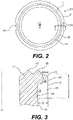
- Figure 2 is a top view of the bottle 100.
- details of the upper surface 111 of the crimp ring 110 can be seen.
- Extending from the upper surface 111 is a first sealing ring 118 and a second sealing ring 120.
- the sealing rings 118 and 120 engage a gasket when a valve is crimped to the bottle 100, which thereby creates a seal that prevents contents from leaking out of the bottle 100.
- Having two sealing rings 118 and 120 ensures that an adequate seal is formed even if there are any imperfections in one of the sealing rings 118 and 120.
- two pressure relief slots 116 are formed in the crimp ring 110, with the two pressure relief slots 116 being positioned on opposite sides of the bottle 100.
- the pressure relief slots 116 extend from an outer surface 121 of the crimp ring 110 inward toward the axis A1 of the bottle 100, the pressure relief slots 116 do not extend to positions that are closer to the axis A1 than the second sealing ring 120 is positioned from the axis A1.
- the second sealing ring 120 extends completely around the upper surface 111 and is not interrupted by the pressure relief slots 116.
- the embodiment of the bottle 100 shown in Figure 2 includes two pressure relief slots 116.
- the number of pressure relief slots 116 may vary, for example, from two to four, in different embodiments. Still other embodiments of our invention may include only one pressure relief slot 116 formed in the crimp ring 110 while still achieving the pressure relief effects described herein. While in other embodiments, the bottle 100 may have more than four pressure relief slots 116, such as a bottle having six pressure relief slots 116 in another embodiment. Also, when two or more pressure relief slots 116 are used, the pressure relief slots 116 can be provided at different positions on the crimp ring 110, with the pressure relief slots 116 not necessarily being equidistant from each other.
- Figure 3 is a cross-sectional view taken through one of the pressure relief slots 116 shown in Figures 1 and 2 .
- a first section 122 of the pressure relief slot 116 extends a distance x1 from the outer surface 121 towards the axis A1 of the bottle 100.
- a second section 124 extends a distance x2 from the outer surface 121 towards the axis A1.
- the pressure relief slot 116 is configured such that the distance x2 is greater than the distance x1, thus, a distinct step is formed in the slot 116.
- the first section 122 of the pressure relief slot 116 extends less than half of the height z of the slot 116, while the second section 124 extends more than half of the height z of the slot.
- this configuration of the pressure relief slot 116 with the first and second sections 122 and 124 allows for a passageway to be opened such that gas can be effectively released from a pressurized system using the bottle 100 when the system is heated to an elevated temperature.
- the surface 119 of the bottle 100 within the first section 122 of the pressure relief slot 116 is positioned further from the axis A1 of the bottle 100 than the second sealing projection 120. That is, the first section 122 of the pressure relief slot 116 is not formed into the crimp ring 110 such that any part of the second sealing projection 120 is removed.
- the second section 124 is formed such that the surface 123 of the bottle 100 in the second section 124 is the same distance from the axis A1 as the adjacent surface 126 of the bottle 100. It should be noted, however, that in other embodiments, the second section 124 is formed at a different distance from the axis A1 than the adjacent surface 126 such that a second distinct step is formed within the pressure relief slot 116. And, those skilled in the art will appreciate that the two-section pressure relief slot 116 depicted in Figure 3 could be varied in other ways while still achieving the pressure relief and sealing features described herein.
- Figure 4 shows the finish of the bottle 100 along with a valve 200 crimped to the crimp ring 110.
- the valve 200 includes a trigger mechanism 202 connected to a dip tube 201 that extends down into the bottle 100.
- product in the bottle 100 moves through the dip tube 201 and trigger mechanism 202 as it is discharged from the system.
- the trigger mechanism 202 and dip tube 201 are well known in the art and therefore not shown in detail in Figure 4 .
- the valve 200 includes a cup 203 that is set to the opening at the top end 102 of the bottle 100.
- An outer portion 204 of the cup 203 extends over the upper surface 111 and around the crimp ring 110 of the bottle 100.
- the valve 200 is thereby firmly attached to the bottle 100. More specifically, with this crimping of the valve 200 to the crimp ring 110, the valve 200 is securely attached to the bottle 100 so that the valve 200 will remain in place when the bottle is pressurized with a product.
- a gasket 300 is positioned between the top surface 111 of the crimp ring 110 and the valve 200, with the gasket 300 being compressed when the valve 200 is crimped to the crimp ring 110. This tight seal is sufficient to maintain the pressure inside the bottle over a long time.
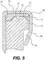
- Figure 5 is a cross-sectional view of a portion of the finish 108 of the bottle 100 with the pressure relief slot 116 and the crimped valve 200. Because of the stepped, two-section configuration of the pressure relief slot 116, the second sealing projection 120 is present at a position adjacent to the slot 116 and engaged to the gasket 300. Further, the gasket 300 is configured so as to contact the first sealing projection 118, a first (inside) surface 302 of the valve 200, a second (outside) surface 304 of the valve 200, and the full length of a surface 306 of the valve 200 that extends between the first surface 302 and the second surface 304.
- the gasket 300 fills almost all of the space between the upper surface 111 of the crimp ring 110 and the valve 200.
- the configuration of the pressure relief slots 116 according to our invention is such that no part of the second sealing projection 120 is removed by the pressure relief slots 116.
- the bottle 100 according to our invention is provided with the pressure relief slots 116 without disrupting the seal between the bottle 100 and valve 200.
- the gasket 300 is a butyl gasket, which we have found to work well because of the compressible nature of such a gasket.
- the gasket 300 could be made from rubber, buna, neoprene, EPDM rubber, fluorocarbons, nitriles, polypropylene, or polyethylene.
- FIGS 6A and 6B are views of portions of the finish 108 and crimped valve 200 showing a condition where the bottle 100 is exposed to an elevated temperature.
- an elevated temperature herein, we mean a temperature at or slightly below the heat deflection temperature of the bottle.
- the heat deflection temperature of a plastic material is the temperature at which the plastic deforms under a specific load.
- the heat deflection temperature can be determined, for example, by ASTM D648 or ISO 75 standards.
- a plastic material will actually start to move at temperatures slightly below the heat deflection temperature, and the heat deflection temperature will vary depending on the particular type of plastic and how the plastic has been processed.
- an “elevated temperature” of a bottle herein will be a temperature slightly below the heat deflection temperature where the plastic material of a bottle begins to move.
- a “non-elevated temperature,” as used herein, means temperatures below the elevated temperature where plastic movement begins.
- the bottle 100 when the bottle 100 is made of plastic material such as PET and pressurized to about 965.3 kPa (140 PSIG), the bottle may contort to such a position when exposed to an elevated temperature of about 70 °C or above for time of 2 hours or more. As discussed above, this contortion in the finish 108 of the bottle 100 occurs because, as the plastic bottle 100 is heated, portions of the plastic bottle 100 below will bulge outward.
- the expansion is often particularly acute in portions of the bottle 100 right below the finish 108.
- the finish 108 contorts, as generally shown in Figures 6A and 6B . Absent some sort of pressure relief mechanism whereby gas is discharged from inside of the bottle 100, it can be seen that as the bottle 100 continues to bulge outward, there will come a point where the finish 108 is so contorted that the valve 200 becomes detached from the crimp ring 110. This is potentially a hazardous condition because the high pressure inside the bottle 100 may cause the valve 200 to become detached from the top of the bottle 100.
- the potentially hazardous condition can be averted in most cases because, as shown in Figure 6B , the pressure relief slots 116 in the crimp ring 110 are configured so that a path (as indicated by the arrows) is created for gas to escape the inside of the bottle 100. The gas is thereby discharged from the system through the path while the valve 200 is still attached. That is, the pressure in the bottle 100 is discharged in a controlled manner and the valve 200 remains attached to the bottle 100, even at significantly elevated temperatures.
- Figure 7 shows the results of a pressure relief test that we conducted using a plastic bottle according to an embodiment of our invention.
- the tested bottle was made from PET and configured as described above, with two pressure relief slots and a valve crimped to the top of the bottle.
- the tested bottle had a volume of 296.4 mL and was filled with deionized water and nitrogen to the point where an internal pressure of 965.3 kPa (140 PSIG) was reached.
- the bottle was heated to a temperature of 75 °C.
- the graph in Figure 7 shows the pressure in the bottle over the time the bottle was heated. During the first few minutes of the test, there was a slight initial rise in pressure inside of the bottle, followed by a gradual pressure decrease over the course of about 30 minutes.
- Figure 8 shows the results of tests that compared a plastic bottle having pressure relief slots as described herein to a plastic bottle that did not have any pressure relief slots.
- the bottles each had a volume of 296.4 mL and were initially pressurized with nitrogen to 965.3 kPa (140 PSIG).
- the bottles were then heated to a temperature of 75 °C.
- the pressure inside of the bottle with no pressure relief slots at first slightly decreased. But, when the pressure reached 572.3 kPa (83 PSIG), the valve was blown off of the top of the bottle and the pressure suddenly decreased to zero.
- the pressure moderately fell from 620.5 kPa (90 PSIG) to about 558.5 kPa (81 PSIG).
- the bottle had contorted to the point that the pressure relief passageways were open, so that the gas from the bottle was discharged. But, even with the pressure relief passageways open, it still took more than 50 seconds for the pressure to completely drop to zero. During this entire time, the valve remained attached to the bottle.
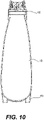
- FIG. 9 An example of a high-pressure dispensing system 400 using the plastic bottle 100 is shown in Figures 9 and 10 .
- the rounded bottom 114 of the bottle 100 is attached to a base cup 600. Details of the base cup 600 and how the base cup 600 is attached to the bottle 100 can be found in U.S. Patent Application No. 15/166,337 .
- the base cup 600 allows the system 400 to stand upright on a flat surface despite the bottle 100 having a rounded bottom 114.
- a spray mechanism 502 which includes a valve 200 as discussed above.
- the pressurized product contained within the bottle 100 is dispensed through the spray mechanism 502.
- a cap may be provided over the spray mechanism 502.
- the system 400 is used to dispense an air freshening composition.
- an air freshening composition examples of formulations for the air freshening composition can be found in U.S. Patent Application No. 15/094,542 .
- pressurized dispensing systems have a wide variety of uses, for example, in the market of aerosol products.
Landscapes
- Chemical & Material Sciences (AREA)
- Dispersion Chemistry (AREA)
- Engineering & Computer Science (AREA)
- Mechanical Engineering (AREA)
- Containers And Packaging Bodies Having A Special Means To Remove Contents (AREA)
- Closures For Containers (AREA)
- Containers Having Bodies Formed In One Piece (AREA)
Description
- Our invention generally relates to a pressurized dispensing system that includes a plastic bottle. Such a system can be used to dispense, for example, an aerosol spray. More specifically, our invention relates to a dispensing system that includes a plastic bottle for containing a product under pressure, with the bottle finish including slots to allow gas to escape in a controlled manner when the bottle is exposed to an elevated temperature, and the bottle being effectively sealed at non-elevated temperatures (e.g., room temperature).
- Pressurized dispensing systems, such as systems used to dispense aerosol products, have conventionally included metallic (e.g., steel or aluminum) containers for containing the product under pressure before it is dispensed from the system. Examples of products that are dispensed with such systems include air fresheners, fabric fresheners, insect repellants, paints, body sprays, hair sprays, shoe or footwear spray products, whipped cream, and processed cheese. Recently, there has been increased interest in using plastic bottles as an alternative to metallic containers in pressurized dispensing systems because plastic bottles have several potential advantages. For example, plastic bottles may be easier and cheaper to manufacture than metallic containers, and plastic bottles can be made in a wider variety of interesting shapes than metallic containers.
- When a pressurized dispensing system is heated, the pressure inside of the system's container increases and/or the volume of the container increases. In systems that use a plastic bottle for containing the product, exposure of the system to anelevated temperature (e.g., 70 °C for a plastic bottle made from polyethylene terephthalate (PET)) can cause an increase in the volume of the bottle. The increased volume may not be evenly distributed symmetrically throughout the bottle. For example, the plastic bottle may bulge outward in some areas, while not bulging in other areas. This bulging in the plastic bottle can lead to a potentially hazardous condition where the bottle contorts in such a way that a valve becomes less firmly attached to the bottle. Eventually, as the bottle contorts more and more, the valve may detach from the top of the bottle, becoming a projectile, which might injure a person in the vicinity of the bottle.
-
U.S. Patent No. 5,199,615 discloses an aerosol dispenser including a plastic bottle having a pressure relief mechanism designed to help alleviate the problem of a valve detaching from the bottle when the dispenser is exposed to an elevated temperature. In particular, the finish of the bottle, to which a valve is attached, is provided with a plurality of slots. The bottle and valve are configured such that when the bottle is heated a pathway is created through the slots to outside of the dispenser. The pathway allows for gas inside of the bottle to rapidly discharge, thereby relieving pressure, so that the valve does not detach from the top of the bottle. - While the pressure relief slots in
U.S. Patent No. 5,199,615 may reduce the possibility of the valve detaching from the top of the bottle when the system is heated, we have found that the configurations of the slots shown in that patent result in an ineffective seal being formed between the bottle and valve. As such, any minor imperfection in the finish could cause gas from inside the bottle to leak from the system. Notably, there could be a significant pressure drop in a matter of minutes. This is very undesirable as pressurized dispensing systems are often used for products that have a shelf-life of multiple years. - According to one aspect, our invention provides a plastic bottle according to
claim 1. - According to another aspect, our invention provides a pressured dispensing system according to claim 6.
-
-
FIG. 1 is a side view of a bottle according to an embodiment of our invention. -
FIG. 2 is a top view of the bottle shown inFIG. 1 . -
FIG. 3 is a cross-sectional view of a portion of the finish of the bottle shown inFIGS. 1 and2 , as taken along line 3-3 shown inFIG. 2 . -
FIG. 4 is a cross-sectional view of a valve crimped to the finish of the bottle shown inFIG. 1 , with the cross section being taken along line 4-4 shown inFIG. 1 . -
FIG. 5 is a detailed view of the valve crimped to the finish shown inFIG. 4 as seen through a part of the finish portion that includes a pressure relief slot. -
FIGS. 6A and 6B are cross-sectional views of portions of the finish and crimped valve as shown inFIGS. 4 and5 when the bottle is exposed to an elevated temperature. -
FIG. 7 shows the results of a test with a bottle according to an embodiment of our invention. -
FIG. 8 shows the results of a test with a bottle according to an embodiment of our invention and a comparison bottle. -
FIG. 9 is a side view of a pressurized dispensing system according to an embodiment of our invention. -
FIG. 10 is a cross-sectional view of the pressurized dispensing system shown inFIG. 9 as taken along line 10-10. - Our invention generally relates to a pressurized dispensing system that includes a plastic bottle. More specifically, our invention relates to a dispensing system that includes a plastic bottle for containing a product under pressure, with the bottle finish including slots to allow gas to escape in a controlled manner when the bottle is exposed to an elevated temperature, and the bottle being effectively sealed at non-elevated temperatures (e.g., room temperature).
- In the descriptions that follow, we will sometimes explain features of our invention in the specific context of an aerosol dispensing system. Those skilled in the art will readily appreciate, however, that our invention is not limited to use with aerosol products. Rather, the pressurized dispensing systems described herein could alternatively be used in conjunction with products other than aerosols. For example, the dispensing systems described herein might be used to dispense foam products such as shaving cream or soap, or used to dispense food products such as soda, whipped cream, or processed cheese.
-
Figure 1 shows abottle 100 for dispensing an aerosol product according to an embodiment of our invention. For clarity, this figure does not include some of the components that would be a part of a complete dispensing system that includes thebottle 100. For example, a spray mechanism is not shown at the top of thebottle 100 inFigure 1 , nor does thebottle 100 include a structure at the bottom (e.g., a base cup) that allows thebottle 100 to stand upright. A more complete description of a dispensing system using thebottle 100 will be described below. - The
bottle 100 in according to the invention is made from a plastic material. As such, thebottle 100 may be formed using, for example, injection, compression, and/or blow molding techniques, which are well known in the art. In injection and blow molding processes, a plastic preform is first formed using injection molding. The plastic preform is subsequently heated and stretch blow molded into the final shape of thebottle 100. Some examples of such plastics include branched or linear PET, polycarbonate (PC), polyethylene naphthalate (PEN), nylon, polyethylene furanoate (PEF), polyolefins (PO) such as polyethylene (PE) and polypropylene (PP), and other polyesters, and blends thereof. It should be noted that the shape, size, and proportions of thebottle 100 shown inFigure 1 are merely exemplary. Indeed, one of the advantages of using plastic to form thebottle 100 is that the plastic may be molded into a wide variety of shapes and sizes. - The
bottle 100 includes anupper end 102, alower end 106, and abody 104 between the upper andlower ends body 104 of thebottle 100 is round and extends about an axis A1. Theupper end 102 includes afinish 108 having acrimp ring 110 surrounding an opening 112 of thebottle 100. As will be explained in detail below, apressure relief slot 116 is provided in thecrimp ring 110, and a valve (not shown) can be crimped to thecrimp ring 110 in order to securely attach the valve to thebottle 100. In theparticular bottle 100 shown inFigure 1 , thebody 104 slightly bows outward from the axis A1 towards thelower end 106 of thebottle 100. In other embodiments, however, thebody 104 of thebottle 100 is formed in different shapes. For example, thebottle 100 may be cylindrical through the length of thebody 104. Arounded bottom 114 is formed at thelower end 106 thebottle 100. An additional structure (e.g., a base cup) can be provided to therounded bottom 114 in order to allow thebottle 100 to stand upright. But, in other embodiments, thebottom 114 of thebottle 100 may be formed in a different shape so that the bottle can stand upright without the provision of an additional structure attached to the bottom 114. -
Figure 2 is a top view of thebottle 100. In this figure, details of theupper surface 111 of thecrimp ring 110 can be seen. Extending from theupper surface 111 is afirst sealing ring 118 and asecond sealing ring 120. As will be explained more fully below, the sealing rings 118 and 120 engage a gasket when a valve is crimped to thebottle 100, which thereby creates a seal that prevents contents from leaking out of thebottle 100. Having two sealingrings Figure 2 , twopressure relief slots 116 are formed in thecrimp ring 110, with the twopressure relief slots 116 being positioned on opposite sides of thebottle 100. Notably, while thepressure relief slots 116 extend from anouter surface 121 of thecrimp ring 110 inward toward the axis A1 of thebottle 100, thepressure relief slots 116 do not extend to positions that are closer to the axis A1 than thesecond sealing ring 120 is positioned from the axis A1. Thus, thesecond sealing ring 120 extends completely around theupper surface 111 and is not interrupted by thepressure relief slots 116. - The embodiment of the
bottle 100 shown inFigure 2 includes twopressure relief slots 116. The number ofpressure relief slots 116 may vary, for example, from two to four, in different embodiments. Still other embodiments of our invention may include only onepressure relief slot 116 formed in thecrimp ring 110 while still achieving the pressure relief effects described herein. While in other embodiments, thebottle 100 may have more than fourpressure relief slots 116, such as a bottle having sixpressure relief slots 116 in another embodiment. Also, when two or morepressure relief slots 116 are used, thepressure relief slots 116 can be provided at different positions on thecrimp ring 110, with thepressure relief slots 116 not necessarily being equidistant from each other. -
Figure 3 is a cross-sectional view taken through one of thepressure relief slots 116 shown inFigures 1 and2 . Afirst section 122 of thepressure relief slot 116 extends a distance x1 from theouter surface 121 towards the axis A1 of thebottle 100. Below thefirst section 122, asecond section 124 extends a distance x2 from theouter surface 121 towards the axis A1. Thepressure relief slot 116 is configured such that the distance x2 is greater than the distance x1, thus, a distinct step is formed in theslot 116. Further, thefirst section 122 of thepressure relief slot 116 extends less than half of the height z of theslot 116, while thesecond section 124 extends more than half of the height z of the slot. As will be further explained below, we have found that this configuration of thepressure relief slot 116 with the first andsecond sections bottle 100 when the system is heated to an elevated temperature. Also, as shown in bothFigure 2 and Figure 3 , thesurface 119 of thebottle 100 within thefirst section 122 of thepressure relief slot 116 is positioned further from the axis A1 of thebottle 100 than thesecond sealing projection 120. That is, thefirst section 122 of thepressure relief slot 116 is not formed into thecrimp ring 110 such that any part of thesecond sealing projection 120 is removed. This is a significant feature of our invention because thesecond sealing projection 120 is important in forming a good seal between thebottle 100 and a valve crimped to thecrimp ring 110. Thus, with the configuration of thepressure relief slot 116 shown inFigure 3 , a system can be created that is both well sealed and has a mechanism for alleviating pressure inside thebottle 100 when the system is excessively heated. - Other aspects of the
pressure relief slot 116 are shown inFigure 3 . For example, thesecond section 124 is formed such that thesurface 123 of thebottle 100 in thesecond section 124 is the same distance from the axis A1 as theadjacent surface 126 of thebottle 100. It should be noted, however, that in other embodiments, thesecond section 124 is formed at a different distance from the axis A1 than theadjacent surface 126 such that a second distinct step is formed within thepressure relief slot 116. And, those skilled in the art will appreciate that the two-sectionpressure relief slot 116 depicted inFigure 3 could be varied in other ways while still achieving the pressure relief and sealing features described herein. -
Figure 4 shows the finish of thebottle 100 along with avalve 200 crimped to thecrimp ring 110. Thevalve 200 includes atrigger mechanism 202 connected to adip tube 201 that extends down into thebottle 100. In a system withbottle 100 andvalve 200, product in thebottle 100 moves through thedip tube 201 andtrigger mechanism 202 as it is discharged from the system. Thetrigger mechanism 202 anddip tube 201 are well known in the art and therefore not shown in detail inFigure 4 . - The
valve 200 includes acup 203 that is set to the opening at thetop end 102 of thebottle 100. Anouter portion 204 of thecup 203 extends over theupper surface 111 and around thecrimp ring 110 of thebottle 100. Thevalve 200 is thereby firmly attached to thebottle 100. More specifically, with this crimping of thevalve 200 to thecrimp ring 110, thevalve 200 is securely attached to thebottle 100 so that thevalve 200 will remain in place when the bottle is pressurized with a product. To create a tight seal between thebottle 100 and thevalve 200, agasket 300 is positioned between thetop surface 111 of thecrimp ring 110 and thevalve 200, with thegasket 300 being compressed when thevalve 200 is crimped to thecrimp ring 110. This tight seal is sufficient to maintain the pressure inside the bottle over a long time. -
Figure 5 is a cross-sectional view of a portion of thefinish 108 of thebottle 100 with thepressure relief slot 116 and the crimpedvalve 200. Because of the stepped, two-section configuration of thepressure relief slot 116, thesecond sealing projection 120 is present at a position adjacent to theslot 116 and engaged to thegasket 300. Further, thegasket 300 is configured so as to contact thefirst sealing projection 118, a first (inside)surface 302 of thevalve 200, a second (outside)surface 304 of thevalve 200, and the full length of asurface 306 of thevalve 200 that extends between thefirst surface 302 and thesecond surface 304. In other words, thegasket 300 fills almost all of the space between theupper surface 111 of thecrimp ring 110 and thevalve 200. We have found that in order to maintain the pressure inside thebottle 100 over an extended period of time (e.g., many months), it is necessary to have thegasket 300 substantially fill the space between thecrimp ring 110 and thevalve 200, and to have thegasket 300 engaged to both thefirst sealing projection 118 and thesecond sealing projection 120 all the way around theupper surface 111 of thecrimp ring 110. And, as discussed above, the configuration of thepressure relief slots 116 according to our invention is such that no part of thesecond sealing projection 120 is removed by thepressure relief slots 116. Thus, thebottle 100 according to our invention is provided with thepressure relief slots 116 without disrupting the seal between thebottle 100 andvalve 200. - In particular embodiments of our invention, the
gasket 300 is a butyl gasket, which we have found to work well because of the compressible nature of such a gasket. Those skill in the art will recognize, however, that other types of gaskets might be used. For example, thegasket 300 could be made from rubber, buna, neoprene, EPDM rubber, fluorocarbons, nitriles, polypropylene, or polyethylene. -
Figures 6A and 6B are views of portions of thefinish 108 and crimpedvalve 200 showing a condition where thebottle 100 is exposed to an elevated temperature. When referring an "elevated temperature" herein, we mean a temperature at or slightly below the heat deflection temperature of the bottle. As will be appreciated by those skilled in the art, the heat deflection temperature of a plastic material is the temperature at which the plastic deforms under a specific load. The heat deflection temperature can be determined, for example, by ASTM D648 or ISO 75 standards. As will also be appreciated by those skilled in the art, a plastic material will actually start to move at temperatures slightly below the heat deflection temperature, and the heat deflection temperature will vary depending on the particular type of plastic and how the plastic has been processed. Thus, an "elevated temperature" of a bottle herein will be a temperature slightly below the heat deflection temperature where the plastic material of a bottle begins to move. And, a "non-elevated temperature," as used herein, means temperatures below the elevated temperature where plastic movement begins. Generally speaking, in embodiments of our invention when thebottle 100 is made of plastic material such as PET and pressurized to about 965.3 kPa (140 PSIG), the bottle may contort to such a position when exposed to an elevated temperature of about 70 °C or above for time of 2 hours or more. As discussed above, this contortion in thefinish 108 of thebottle 100 occurs because, as theplastic bottle 100 is heated, portions of theplastic bottle 100 below will bulge outward. The expansion is often particularly acute in portions of thebottle 100 right below thefinish 108. Thus, thefinish 108 contorts, as generally shown inFigures 6A and 6B . Absent some sort of pressure relief mechanism whereby gas is discharged from inside of thebottle 100, it can be seen that as thebottle 100 continues to bulge outward, there will come a point where thefinish 108 is so contorted that thevalve 200 becomes detached from thecrimp ring 110. This is potentially a hazardous condition because the high pressure inside thebottle 100 may cause thevalve 200 to become detached from the top of thebottle 100. But, with our invention, the potentially hazardous condition can be averted in most cases because, as shown inFigure 6B , thepressure relief slots 116 in thecrimp ring 110 are configured so that a path (as indicated by the arrows) is created for gas to escape the inside of thebottle 100. The gas is thereby discharged from the system through the path while thevalve 200 is still attached. That is, the pressure in thebottle 100 is discharged in a controlled manner and thevalve 200 remains attached to thebottle 100, even at significantly elevated temperatures. -
Figure 7 shows the results of a pressure relief test that we conducted using a plastic bottle according to an embodiment of our invention. The tested bottle was made from PET and configured as described above, with two pressure relief slots and a valve crimped to the top of the bottle. The tested bottle had a volume of 296.4 mL and was filled with deionized water and nitrogen to the point where an internal pressure of 965.3 kPa (140 PSIG) was reached. During the test, the bottle was heated to a temperature of 75 °C. The graph inFigure 7 shows the pressure in the bottle over the time the bottle was heated. During the first few minutes of the test, there was a slight initial rise in pressure inside of the bottle, followed by a gradual pressure decrease over the course of about 30 minutes. Without being bound by theory, we believe that the initial rise in pressure was due to the gas in the bottle being heated. As the test continued, the temperature of the bottle increased. The increased heat energy in the bottle caused movement of the PET polymers making up the bottle, which created more free volume between the chains of polymers. With the additional free volume, the pressure inside of the bottle caused the polymer chains to move and the bottle expanded. And with the expansion of the bottle the pressure decreased as the test continued. When the pressure reached about 551.6 kPa (80 PSIG), there was a quick drop in pressure. This pressure fall off below about 551.6 kPa (80 PSIG) occurred because the bottle had contorted to a point that the passageways formed by the pressure relief slots were open and gas from inside of the bottle was discharged through the passageways. Importantly, during the entire test, the valve remained attached to the top of the bottle. Thus, while the pressure release from about 551.6 kPa (80 PSIG) to zero occurred relatively quickly, this pressure drop to zero was not instantaneous, as would have been the case if the valve had detached from the top of the bottle. -
Figure 8 shows the results of tests that compared a plastic bottle having pressure relief slots as described herein to a plastic bottle that did not have any pressure relief slots. In these tests, the bottles each had a volume of 296.4 mL and were initially pressurized with nitrogen to 965.3 kPa (140 PSIG). The bottles were then heated to a temperature of 75 °C. As shown inFigure 8 , the pressure inside of the bottle with no pressure relief slots at first slightly decreased. But, when the pressure reached 572.3 kPa (83 PSIG), the valve was blown off of the top of the bottle and the pressure suddenly decreased to zero. On the other hand, in the bottle according to our invention, the pressure moderately fell from 620.5 kPa (90 PSIG) to about 558.5 kPa (81 PSIG). At that point, the bottle had contorted to the point that the pressure relief passageways were open, so that the gas from the bottle was discharged. But, even with the pressure relief passageways open, it still took more than 50 seconds for the pressure to completely drop to zero. During this entire time, the valve remained attached to the bottle. - An example of a high-
pressure dispensing system 400 using theplastic bottle 100 is shown inFigures 9 and10 . In thesystem 400, therounded bottom 114 of thebottle 100 is attached to abase cup 600. Details of thebase cup 600 and how thebase cup 600 is attached to thebottle 100 can be found inU.S. Patent Application No. 15/166,337 . Thebase cup 600 allows thesystem 400 to stand upright on a flat surface despite thebottle 100 having arounded bottom 114. At the top of thesystem 400 is aspray mechanism 502, which includes avalve 200 as discussed above. The pressurized product contained within thebottle 100 is dispensed through thespray mechanism 502. Although not shown, a cap may be provided over thespray mechanism 502. - In a specific embodiment of our invention, the
system 400 is used to dispense an air freshening composition. Examples of formulations for the air freshening composition can be found inU.S. Patent Application No. 15/094,542 . - Although this invention has been described in certain specific exemplary embodiments, many additional modifications and variations that fall within the scope of the claims would be apparent to those skilled in the art in light of this disclosure. It is, therefore, to be understood that this invention may be practiced otherwise than as specifically described. Thus, the exemplary embodiments of the invention should be considered in all respects to be illustrative and not restrictive, and the scope of the invention to be determined by any claims, rather than by the foregoing description.
- The invention described herein can be used in the commercial production of a pressurized dispensing system. Such pressurized dispensing systems have a wide variety of uses, for example, in the market of aerosol products.
Claims (9)
- A plastic bottle (100) including:(a) a base (114) at a bottom end (106) of the bottle (100);(b) a body (104) extending about an axis of the bottle (100) from the base (114) towards a top end (102) of the bottle (100); and(c) a finish (108) extending about the axis of the bottle (100) from the body (104) to the top end (102) of the bottle (100), wherein the finish (108) includes:wherein the first section (122) extends less than half of a length of the crimp ring (110) in the axial direction, and the second section (124) extends more than half of the length of the crimp ring (110) in the axial direction.(i) a crimp ring (110) extending outwardly from an adjacent surface (126) of the finish (108), the crimp ring (110) forming an upper surface (111) of the bottle (100) and an outer surface (121) of the bottle (100);(ii) a first sealing projection (118) extending from the upper surface (111); and(iii) a second sealing projection (120) extending from the upper surface (111), the second sealing projection (120) being positioned a further distance from the axis of the bottle (100) than the first sealing projection (118) is positioned from the axis of the bottle (100),wherein the crimp ring (110) comprises at least one slot (116) that extends inwardly from the outer surface (121), the at least one slot (116) including a first section (122) extending from the upper surface (111), and a second section (124) below the first section (122), the second section (124) being a shorter distance from the axis of the bottle (100) than the first section (122) is distanced from the axis of the bottle (100), and
- The plastic bottle (100) according to claim 1, wherein the first section (122) is a further distance from the axis of the bottle (100) than the second sealing projection (120) is positioned from the axis of the bottle (100).
- The plastic bottle (100) according to claims 1 or 2, wherein the second section (124) is the same distance from the axis of the bottle (100) as the adjacent surface (126) of the finish (108).
- The plastic bottle (100) according to any one of the preceding claims, wherein the second sealing projection (120) includes a portion that is the same distance from the axis as the adjacent surface (126) of the finish (108) is distanced from the axis.
- The plastic bottle (100) according to any one of the preceding claims, wherein two to four slots are provided in the crimp ring (108).
- A pressurized dispensing system (400) comprising:(A) a plastic bottle (100) according to any one of the preceding claims:(B) a valve (200) crimped to the crimp ring (110) ; and(C) a gasket (300) positioned between the upper surface (111) and the valve (200) such that a seal is formed between the bottle (100) and valve (200).
- The pressurized dispensing system (400) according to claim 6, wherein the gasket (300) is compressed so as to substantially fill the space between the upper surface (111) and the valve (200).
- The pressurized dispensing system (400) according to claim 7, wherein the compressed gasket (300) contacts the first sealing projection (118), the second sealing projection (120), a first surface (302) of the valve (200), a second surface (304) of the valve (200) that is positioned opposite to the first surface (302) of the valve (200), and a full length of a surface (306) of the valve (200) that spans between the first and second surfaces (302, 304).
- The pressurized dispensing system (400) according to claim 6, wherein the gasket (300) is a butyl gasket.
Applications Claiming Priority (2)
| Application Number | Priority Date | Filing Date | Title |
|---|---|---|---|
| US15/367,651 US10633168B2 (en) | 2016-12-02 | 2016-12-02 | Pressurized dispensing system including a plastic bottle |
| PCT/US2017/063826 WO2018102481A1 (en) | 2016-12-02 | 2017-11-30 | Pressurized dispensing system including a plastic bottle |
Publications (2)
| Publication Number | Publication Date |
|---|---|
| EP3548403A1 EP3548403A1 (en) | 2019-10-09 |
| EP3548403B1 true EP3548403B1 (en) | 2022-08-24 |
Family
ID=60766160
Family Applications (1)
| Application Number | Title | Priority Date | Filing Date |
|---|---|---|---|
| EP17817976.8A Active EP3548403B1 (en) | 2016-12-02 | 2017-11-30 | Pressurized dispensing system including a plastic bottle |
Country Status (11)
| Country | Link |
|---|---|
| US (1) | US10633168B2 (en) |
| EP (1) | EP3548403B1 (en) |
| JP (1) | JP7080235B2 (en) |
| KR (1) | KR102593772B1 (en) |
| CN (1) | CN110139809B (en) |
| AR (1) | AR110480A1 (en) |
| AU (1) | AU2017368159B2 (en) |
| BR (1) | BR112019011362B1 (en) |
| ES (1) | ES2928205T3 (en) |
| MX (1) | MX2019006405A (en) |
| WO (1) | WO2018102481A1 (en) |
Families Citing this family (9)
| Publication number | Priority date | Publication date | Assignee | Title |
|---|---|---|---|---|
| US10518961B2 (en) | 2017-11-06 | 2019-12-31 | The Procter & Gamble Company | Aerosol dispenser with improved neck geometry outer container therefor and preform therefor |
| US10640284B2 (en) | 2017-11-06 | 2020-05-05 | The Procter & Gamble Company | Aerosol dispenser with vented valve cup and valve cup therefor |
| US10589921B2 (en) * | 2017-11-06 | 2020-03-17 | The Procter & Gamble Company | Aerosol dispenser with integral vent outer container therefor and preform therefor |
| US10894657B2 (en) * | 2018-01-03 | 2021-01-19 | The Procter & Gamble Company | Divergently vented aerosol dispenser outer container therefor and preform therefor |
| US10836561B2 (en) | 2018-10-08 | 2020-11-17 | The Procter & Gamble Company | Aerosol dispenser |
| WO2021020666A1 (en) | 2019-07-26 | 2021-02-04 | Brexogen Inc. | Precursor cells of induced pluripotent stem cell-derived mesenchymal stem cells and method for preparing the same |
| US11174092B2 (en) | 2019-11-25 | 2021-11-16 | The Procter & Gamble Company | Recyclable aerosol dispensers |
| US10961043B1 (en) * | 2020-03-05 | 2021-03-30 | The Procter & Gamble Company | Aerosol container with spaced sealing beads |
| EP4277755A1 (en) | 2021-01-17 | 2023-11-22 | S. C. Johnson & Son, Inc. | Aerosol sprays, methods of generating aerosol sprays, and aerosol dispensing systems |
Citations (1)
| Publication number | Priority date | Publication date | Assignee | Title |
|---|---|---|---|---|
| WO2019090281A1 (en) * | 2017-11-06 | 2019-05-09 | The Procter & Gamble Company | Aerosol dispenser with vented valve cup and valve cup therefor |
Family Cites Families (18)
| Publication number | Priority date | Publication date | Assignee | Title |
|---|---|---|---|---|
| GB2205614B (en) | 1987-06-11 | 1991-03-27 | Fibrenyle Ltd | Dispenser with pressure release mechanism. |
| US5052577A (en) * | 1989-11-07 | 1991-10-01 | Armstrong Laboratories, Inc. | Container assembly |
| DE4305130A1 (en) * | 1992-06-16 | 1993-12-23 | Raku Gmbh | Process for manufacturing a container |
| JPH07149382A (en) * | 1993-11-22 | 1995-06-13 | Osaka Zosenjo:Kk | Aerosol device with safety mechanism |
| JP2757277B2 (en) * | 1994-04-28 | 1998-05-25 | 花王株式会社 | Aerosol container |
| DE19906576B4 (en) * | 1999-02-17 | 2007-08-02 | Wella Ag | aerosol container |
| JP3749051B2 (en) * | 1999-10-29 | 2006-02-22 | 株式会社吉野工業所 | Aerosol container that prevents explosion |
| CH694802A5 (en) * | 2000-12-07 | 2005-07-29 | Createchnic Ag | Spray container of preservative-free drugs sprays. |
| US7033656B2 (en) | 2002-04-12 | 2006-04-25 | Graham Packaging Pet Technologies, Inc. | Graded crystallization of container finishes |
| JP2005162231A (en) | 2003-11-28 | 2005-06-23 | Hoyu Co Ltd | Aerosol container |
| US6971530B2 (en) | 2003-12-12 | 2005-12-06 | Plastipak Packaging, Inc. | Plastic container having stepped neck finish |
| JP3680068B2 (en) * | 2003-12-26 | 2005-08-10 | 株式会社ダイゾー | Container body for aerosol device |
| JP4589715B2 (en) * | 2004-12-20 | 2010-12-01 | 花王株式会社 | Aerosol container |
| JP5283939B2 (en) * | 2008-03-19 | 2013-09-04 | 株式会社三谷バルブ | Aerosol container and aerosol product using the aerosol container |
| WO2011090457A1 (en) * | 2010-01-22 | 2011-07-28 | Aptargroup, Inc. | Improved neck-finish for an aerosol container |
| JP6057148B2 (en) | 2012-05-30 | 2017-01-11 | 株式会社吉野工業所 | Aerosol container |
| JP5945938B2 (en) | 2012-05-30 | 2016-07-05 | 株式会社吉野工業所 | Aerosol container |
| WO2016161338A1 (en) * | 2015-04-01 | 2016-10-06 | Graham Packaging Company, L.P. | Structure and method of sealing a closure assembly onto the neck finish of a plastic pressure container |
-
2016
- 2016-12-02 US US15/367,651 patent/US10633168B2/en active Active
-
2017
- 2017-11-30 CN CN201780081604.5A patent/CN110139809B/en active Active
- 2017-11-30 BR BR112019011362-2A patent/BR112019011362B1/en active IP Right Grant
- 2017-11-30 JP JP2019528804A patent/JP7080235B2/en active Active
- 2017-11-30 WO PCT/US2017/063826 patent/WO2018102481A1/en not_active Ceased
- 2017-11-30 KR KR1020197015925A patent/KR102593772B1/en active Active
- 2017-11-30 EP EP17817976.8A patent/EP3548403B1/en active Active
- 2017-11-30 AU AU2017368159A patent/AU2017368159B2/en active Active
- 2017-11-30 ES ES17817976T patent/ES2928205T3/en active Active
- 2017-11-30 MX MX2019006405A patent/MX2019006405A/en unknown
- 2017-12-01 AR ARP170103378A patent/AR110480A1/en active IP Right Grant
Patent Citations (1)
| Publication number | Priority date | Publication date | Assignee | Title |
|---|---|---|---|---|
| WO2019090281A1 (en) * | 2017-11-06 | 2019-05-09 | The Procter & Gamble Company | Aerosol dispenser with vented valve cup and valve cup therefor |
Also Published As
| Publication number | Publication date |
|---|---|
| US10633168B2 (en) | 2020-04-28 |
| ES2928205T3 (en) | 2022-11-16 |
| CN110139809A (en) | 2019-08-16 |
| WO2018102481A1 (en) | 2018-06-07 |
| EP3548403A1 (en) | 2019-10-09 |
| JP7080235B2 (en) | 2022-06-03 |
| JP2019536705A (en) | 2019-12-19 |
| KR102593772B1 (en) | 2023-10-25 |
| AR110480A1 (en) | 2019-04-03 |
| CN110139809B (en) | 2021-07-02 |
| AU2017368159A1 (en) | 2019-06-06 |
| AU2017368159B2 (en) | 2020-05-14 |
| BR112019011362A2 (en) | 2019-10-15 |
| US20180155115A1 (en) | 2018-06-07 |
| MX2019006405A (en) | 2019-08-14 |
| KR20190091269A (en) | 2019-08-05 |
| BR112019011362B1 (en) | 2023-12-12 |
Similar Documents
| Publication | Publication Date | Title |
|---|---|---|
| AU2017368159B2 (en) | Pressurized dispensing system including a plastic bottle | |
| EP2807090B1 (en) | Thermoplastic bottle with valve cup retaining protrusions and method of crimping a valve cup on a thermoplastic bottle | |
| US11117735B2 (en) | Valve assembly for dispensers | |
| US11117736B2 (en) | Valve assembly for dispensers | |
| US10427863B2 (en) | Aerosol container, and details thereof | |
| JP5560035B2 (en) | Inner bag and double aerosol product using the same | |
| US10836561B2 (en) | Aerosol dispenser | |
| US10486892B1 (en) | Packages and arrays of packages for plastic aerosol dispensers | |
| JP7220618B2 (en) | Double pressurized container | |
| JP7171384B6 (en) | Pressurized container, pressurized product, dispensing member and dispensing device | |
| KR101645651B1 (en) | Inner container for actuator with dual container structure | |
| KR101653375B1 (en) | Nonmetallic outer container for actuator with dual container structure | |
| JP6157069B2 (en) | Discharge container |
Legal Events
| Date | Code | Title | Description |
|---|---|---|---|
| STAA | Information on the status of an ep patent application or granted ep patent |
Free format text: STATUS: UNKNOWN |
|
| STAA | Information on the status of an ep patent application or granted ep patent |
Free format text: STATUS: THE INTERNATIONAL PUBLICATION HAS BEEN MADE |
|
| PUAI | Public reference made under article 153(3) epc to a published international application that has entered the european phase |
Free format text: ORIGINAL CODE: 0009012 |
|
| STAA | Information on the status of an ep patent application or granted ep patent |
Free format text: STATUS: REQUEST FOR EXAMINATION WAS MADE |
|
| 17P | Request for examination filed |
Effective date: 20190515 |
|
| AK | Designated contracting states |
Kind code of ref document: A1 Designated state(s): AL AT BE BG CH CY CZ DE DK EE ES FI FR GB GR HR HU IE IS IT LI LT LU LV MC MK MT NL NO PL PT RO RS SE SI SK SM TR |
|
| AX | Request for extension of the european patent |
Extension state: BA ME |
|
| DAV | Request for validation of the european patent (deleted) | ||
| DAX | Request for extension of the european patent (deleted) | ||
| RIN1 | Information on inventor provided before grant (corrected) |
Inventor name: BLAIR, CASSANDRA Inventor name: MCGRATH, DANIEL, S. Inventor name: STENMARK, NILES Inventor name: HARRIS, KIMBERLY, J. Inventor name: WOLAK, CHRISTOPHER, P. |
|
| STAA | Information on the status of an ep patent application or granted ep patent |
Free format text: STATUS: EXAMINATION IS IN PROGRESS |
|
| 17Q | First examination report despatched |
Effective date: 20200615 |
|
| GRAP | Despatch of communication of intention to grant a patent |
Free format text: ORIGINAL CODE: EPIDOSNIGR1 |
|
| STAA | Information on the status of an ep patent application or granted ep patent |
Free format text: STATUS: GRANT OF PATENT IS INTENDED |
|
| INTG | Intention to grant announced |
Effective date: 20220322 |
|
| GRAS | Grant fee paid |
Free format text: ORIGINAL CODE: EPIDOSNIGR3 |
|
| GRAA | (expected) grant |
Free format text: ORIGINAL CODE: 0009210 |
|
| STAA | Information on the status of an ep patent application or granted ep patent |
Free format text: STATUS: THE PATENT HAS BEEN GRANTED |
|
| AK | Designated contracting states |
Kind code of ref document: B1 Designated state(s): AL AT BE BG CH CY CZ DE DK EE ES FI FR GB GR HR HU IE IS IT LI LT LU LV MC MK MT NL NO PL PT RO RS SE SI SK SM TR |
|
| REG | Reference to a national code |
Ref country code: CH Ref legal event code: EP |
|
| REG | Reference to a national code |
Ref country code: DE Ref legal event code: R096 Ref document number: 602017061049 Country of ref document: DE |
|
| REG | Reference to a national code |
Ref country code: IE Ref legal event code: FG4D |
|
| REG | Reference to a national code |
Ref country code: AT Ref legal event code: REF Ref document number: 1513526 Country of ref document: AT Kind code of ref document: T Effective date: 20220915 |
|
| REG | Reference to a national code |
Ref country code: ES Ref legal event code: FG2A Ref document number: 2928205 Country of ref document: ES Kind code of ref document: T3 Effective date: 20221116 |
|
| REG | Reference to a national code |
Ref country code: LT Ref legal event code: MG9D |
|
| REG | Reference to a national code |
Ref country code: NL Ref legal event code: MP Effective date: 20220824 |
|
| PG25 | Lapsed in a contracting state [announced via postgrant information from national office to epo] |
Ref country code: SE Free format text: LAPSE BECAUSE OF FAILURE TO SUBMIT A TRANSLATION OF THE DESCRIPTION OR TO PAY THE FEE WITHIN THE PRESCRIBED TIME-LIMIT Effective date: 20220824 Ref country code: RS Free format text: LAPSE BECAUSE OF FAILURE TO SUBMIT A TRANSLATION OF THE DESCRIPTION OR TO PAY THE FEE WITHIN THE PRESCRIBED TIME-LIMIT Effective date: 20220824 Ref country code: PT Free format text: LAPSE BECAUSE OF FAILURE TO SUBMIT A TRANSLATION OF THE DESCRIPTION OR TO PAY THE FEE WITHIN THE PRESCRIBED TIME-LIMIT Effective date: 20221226 Ref country code: NO Free format text: LAPSE BECAUSE OF FAILURE TO SUBMIT A TRANSLATION OF THE DESCRIPTION OR TO PAY THE FEE WITHIN THE PRESCRIBED TIME-LIMIT Effective date: 20221124 Ref country code: NL Free format text: LAPSE BECAUSE OF FAILURE TO SUBMIT A TRANSLATION OF THE DESCRIPTION OR TO PAY THE FEE WITHIN THE PRESCRIBED TIME-LIMIT Effective date: 20220824 Ref country code: LV Free format text: LAPSE BECAUSE OF FAILURE TO SUBMIT A TRANSLATION OF THE DESCRIPTION OR TO PAY THE FEE WITHIN THE PRESCRIBED TIME-LIMIT Effective date: 20220824 Ref country code: LT Free format text: LAPSE BECAUSE OF FAILURE TO SUBMIT A TRANSLATION OF THE DESCRIPTION OR TO PAY THE FEE WITHIN THE PRESCRIBED TIME-LIMIT Effective date: 20220824 Ref country code: FI Free format text: LAPSE BECAUSE OF FAILURE TO SUBMIT A TRANSLATION OF THE DESCRIPTION OR TO PAY THE FEE WITHIN THE PRESCRIBED TIME-LIMIT Effective date: 20220824 |
|
| REG | Reference to a national code |
Ref country code: AT Ref legal event code: MK05 Ref document number: 1513526 Country of ref document: AT Kind code of ref document: T Effective date: 20220824 |
|
| PG25 | Lapsed in a contracting state [announced via postgrant information from national office to epo] |
Ref country code: PL Free format text: LAPSE BECAUSE OF FAILURE TO SUBMIT A TRANSLATION OF THE DESCRIPTION OR TO PAY THE FEE WITHIN THE PRESCRIBED TIME-LIMIT Effective date: 20220824 Ref country code: IS Free format text: LAPSE BECAUSE OF FAILURE TO SUBMIT A TRANSLATION OF THE DESCRIPTION OR TO PAY THE FEE WITHIN THE PRESCRIBED TIME-LIMIT Effective date: 20221224 Ref country code: HR Free format text: LAPSE BECAUSE OF FAILURE TO SUBMIT A TRANSLATION OF THE DESCRIPTION OR TO PAY THE FEE WITHIN THE PRESCRIBED TIME-LIMIT Effective date: 20220824 Ref country code: GR Free format text: LAPSE BECAUSE OF FAILURE TO SUBMIT A TRANSLATION OF THE DESCRIPTION OR TO PAY THE FEE WITHIN THE PRESCRIBED TIME-LIMIT Effective date: 20221125 |
|
| PG25 | Lapsed in a contracting state [announced via postgrant information from national office to epo] |
Ref country code: SM Free format text: LAPSE BECAUSE OF FAILURE TO SUBMIT A TRANSLATION OF THE DESCRIPTION OR TO PAY THE FEE WITHIN THE PRESCRIBED TIME-LIMIT Effective date: 20220824 Ref country code: RO Free format text: LAPSE BECAUSE OF FAILURE TO SUBMIT A TRANSLATION OF THE DESCRIPTION OR TO PAY THE FEE WITHIN THE PRESCRIBED TIME-LIMIT Effective date: 20220824 Ref country code: DK Free format text: LAPSE BECAUSE OF FAILURE TO SUBMIT A TRANSLATION OF THE DESCRIPTION OR TO PAY THE FEE WITHIN THE PRESCRIBED TIME-LIMIT Effective date: 20220824 Ref country code: CZ Free format text: LAPSE BECAUSE OF FAILURE TO SUBMIT A TRANSLATION OF THE DESCRIPTION OR TO PAY THE FEE WITHIN THE PRESCRIBED TIME-LIMIT Effective date: 20220824 Ref country code: AT Free format text: LAPSE BECAUSE OF FAILURE TO SUBMIT A TRANSLATION OF THE DESCRIPTION OR TO PAY THE FEE WITHIN THE PRESCRIBED TIME-LIMIT Effective date: 20220824 |
|
| REG | Reference to a national code |
Ref country code: DE Ref legal event code: R097 Ref document number: 602017061049 Country of ref document: DE |
|
| PG25 | Lapsed in a contracting state [announced via postgrant information from national office to epo] |
Ref country code: SK Free format text: LAPSE BECAUSE OF FAILURE TO SUBMIT A TRANSLATION OF THE DESCRIPTION OR TO PAY THE FEE WITHIN THE PRESCRIBED TIME-LIMIT Effective date: 20220824 Ref country code: EE Free format text: LAPSE BECAUSE OF FAILURE TO SUBMIT A TRANSLATION OF THE DESCRIPTION OR TO PAY THE FEE WITHIN THE PRESCRIBED TIME-LIMIT Effective date: 20220824 |
|
| PG25 | Lapsed in a contracting state [announced via postgrant information from national office to epo] |
Ref country code: MC Free format text: LAPSE BECAUSE OF FAILURE TO SUBMIT A TRANSLATION OF THE DESCRIPTION OR TO PAY THE FEE WITHIN THE PRESCRIBED TIME-LIMIT Effective date: 20220824 Ref country code: AL Free format text: LAPSE BECAUSE OF FAILURE TO SUBMIT A TRANSLATION OF THE DESCRIPTION OR TO PAY THE FEE WITHIN THE PRESCRIBED TIME-LIMIT Effective date: 20220824 |
|
| PLBE | No opposition filed within time limit |
Free format text: ORIGINAL CODE: 0009261 |
|
| REG | Reference to a national code |
Ref country code: CH Ref legal event code: PL |
|
| STAA | Information on the status of an ep patent application or granted ep patent |
Free format text: STATUS: NO OPPOSITION FILED WITHIN TIME LIMIT |
|
| P01 | Opt-out of the competence of the unified patent court (upc) registered |
Effective date: 20230528 |
|
| REG | Reference to a national code |
Ref country code: BE Ref legal event code: MM Effective date: 20221130 |
|
| PG25 | Lapsed in a contracting state [announced via postgrant information from national office to epo] |
Ref country code: LI Free format text: LAPSE BECAUSE OF NON-PAYMENT OF DUE FEES Effective date: 20221130 Ref country code: CH Free format text: LAPSE BECAUSE OF NON-PAYMENT OF DUE FEES Effective date: 20221130 |
|
| 26N | No opposition filed |
Effective date: 20230525 |
|
| PG25 | Lapsed in a contracting state [announced via postgrant information from national office to epo] |
Ref country code: SI Free format text: LAPSE BECAUSE OF FAILURE TO SUBMIT A TRANSLATION OF THE DESCRIPTION OR TO PAY THE FEE WITHIN THE PRESCRIBED TIME-LIMIT Effective date: 20220824 Ref country code: LU Free format text: LAPSE BECAUSE OF NON-PAYMENT OF DUE FEES Effective date: 20221130 |
|
| PG25 | Lapsed in a contracting state [announced via postgrant information from national office to epo] |
Ref country code: IE Free format text: LAPSE BECAUSE OF NON-PAYMENT OF DUE FEES Effective date: 20221130 |
|
| PG25 | Lapsed in a contracting state [announced via postgrant information from national office to epo] |
Ref country code: BE Free format text: LAPSE BECAUSE OF NON-PAYMENT OF DUE FEES Effective date: 20221130 |
|
| PG25 | Lapsed in a contracting state [announced via postgrant information from national office to epo] |
Ref country code: HU Free format text: LAPSE BECAUSE OF FAILURE TO SUBMIT A TRANSLATION OF THE DESCRIPTION OR TO PAY THE FEE WITHIN THE PRESCRIBED TIME-LIMIT; INVALID AB INITIO Effective date: 20171130 |
|
| PG25 | Lapsed in a contracting state [announced via postgrant information from national office to epo] |
Ref country code: CY Free format text: LAPSE BECAUSE OF FAILURE TO SUBMIT A TRANSLATION OF THE DESCRIPTION OR TO PAY THE FEE WITHIN THE PRESCRIBED TIME-LIMIT Effective date: 20220824 |
|
| PG25 | Lapsed in a contracting state [announced via postgrant information from national office to epo] |
Ref country code: MK Free format text: LAPSE BECAUSE OF FAILURE TO SUBMIT A TRANSLATION OF THE DESCRIPTION OR TO PAY THE FEE WITHIN THE PRESCRIBED TIME-LIMIT Effective date: 20220824 |
|
| PG25 | Lapsed in a contracting state [announced via postgrant information from national office to epo] |
Ref country code: TR Free format text: LAPSE BECAUSE OF FAILURE TO SUBMIT A TRANSLATION OF THE DESCRIPTION OR TO PAY THE FEE WITHIN THE PRESCRIBED TIME-LIMIT Effective date: 20220824 |
|
| PG25 | Lapsed in a contracting state [announced via postgrant information from national office to epo] |
Ref country code: BG Free format text: LAPSE BECAUSE OF FAILURE TO SUBMIT A TRANSLATION OF THE DESCRIPTION OR TO PAY THE FEE WITHIN THE PRESCRIBED TIME-LIMIT Effective date: 20220824 |
|
| PG25 | Lapsed in a contracting state [announced via postgrant information from national office to epo] |
Ref country code: MT Free format text: LAPSE BECAUSE OF FAILURE TO SUBMIT A TRANSLATION OF THE DESCRIPTION OR TO PAY THE FEE WITHIN THE PRESCRIBED TIME-LIMIT Effective date: 20220824 |
|
| PGFP | Annual fee paid to national office [announced via postgrant information from national office to epo] |
Ref country code: DE Payment date: 20251022 Year of fee payment: 9 |
|
| PGFP | Annual fee paid to national office [announced via postgrant information from national office to epo] |
Ref country code: GB Payment date: 20251022 Year of fee payment: 9 |
|
| PGFP | Annual fee paid to national office [announced via postgrant information from national office to epo] |
Ref country code: IT Payment date: 20251022 Year of fee payment: 9 |
|
| PGFP | Annual fee paid to national office [announced via postgrant information from national office to epo] |
Ref country code: FR Payment date: 20251022 Year of fee payment: 9 |
|
| PGFP | Annual fee paid to national office [announced via postgrant information from national office to epo] |
Ref country code: ES Payment date: 20251201 Year of fee payment: 9 |