EP3548325B1 - Synchronized transmission - Google Patents
Synchronized transmission Download PDFInfo
- Publication number
- EP3548325B1 EP3548325B1 EP17821486.2A EP17821486A EP3548325B1 EP 3548325 B1 EP3548325 B1 EP 3548325B1 EP 17821486 A EP17821486 A EP 17821486A EP 3548325 B1 EP3548325 B1 EP 3548325B1
- Authority
- EP
- European Patent Office
- Prior art keywords
- transmission
- cam
- synchronizer
- actuation
- wheel
- Prior art date
- Legal status (The legal status is an assumption and is not a legal conclusion. Google has not performed a legal analysis and makes no representation as to the accuracy of the status listed.)
- Active
Links
Images



Classifications
-
- B—PERFORMING OPERATIONS; TRANSPORTING
- B60—VEHICLES IN GENERAL
- B60K—ARRANGEMENT OR MOUNTING OF PROPULSION UNITS OR OF TRANSMISSIONS IN VEHICLES; ARRANGEMENT OR MOUNTING OF PLURAL DIVERSE PRIME-MOVERS IN VEHICLES; AUXILIARY DRIVES FOR VEHICLES; INSTRUMENTATION OR DASHBOARDS FOR VEHICLES; ARRANGEMENTS IN CONNECTION WITH COOLING, AIR INTAKE, GAS EXHAUST OR FUEL SUPPLY OF PROPULSION UNITS IN VEHICLES
- B60K5/00—Arrangement or mounting of internal-combustion or jet-propulsion units
- B60K5/04—Arrangement or mounting of internal-combustion or jet-propulsion units with the engine main axis, e.g. crankshaft axis, transversely to the longitudinal centre line of the vehicle
-
- F—MECHANICAL ENGINEERING; LIGHTING; HEATING; WEAPONS; BLASTING
- F16—ENGINEERING ELEMENTS AND UNITS; GENERAL MEASURES FOR PRODUCING AND MAINTAINING EFFECTIVE FUNCTIONING OF MACHINES OR INSTALLATIONS; THERMAL INSULATION IN GENERAL
- F16H—GEARING
- F16H61/00—Control functions within control units of change-speed- or reversing-gearings for conveying rotary motion ; Control of exclusively fluid gearing, friction gearing, gearings with endless flexible members or other particular types of gearing
- F16H61/26—Generation or transmission of movements for final actuating mechanisms
- F16H61/28—Generation or transmission of movements for final actuating mechanisms with at least one movement of the final actuating mechanism being caused by a non-mechanical force, e.g. power-assisted
-
- B—PERFORMING OPERATIONS; TRANSPORTING
- B60—VEHICLES IN GENERAL
- B60K—ARRANGEMENT OR MOUNTING OF PROPULSION UNITS OR OF TRANSMISSIONS IN VEHICLES; ARRANGEMENT OR MOUNTING OF PLURAL DIVERSE PRIME-MOVERS IN VEHICLES; AUXILIARY DRIVES FOR VEHICLES; INSTRUMENTATION OR DASHBOARDS FOR VEHICLES; ARRANGEMENTS IN CONNECTION WITH COOLING, AIR INTAKE, GAS EXHAUST OR FUEL SUPPLY OF PROPULSION UNITS IN VEHICLES
- B60K17/00—Arrangement or mounting of transmissions in vehicles
- B60K17/04—Arrangement or mounting of transmissions in vehicles characterised by arrangement, location or kind of gearing
- B60K17/043—Transmission unit disposed in on near the vehicle wheel, or between the differential gear unit and the wheel
-
- B—PERFORMING OPERATIONS; TRANSPORTING
- B62—LAND VEHICLES FOR TRAVELLING OTHERWISE THAN ON RAILS
- B62M—RIDER PROPULSION OF WHEELED VEHICLES OR SLEDGES; POWERED PROPULSION OF SLEDGES OR SINGLE-TRACK CYCLES; TRANSMISSIONS SPECIALLY ADAPTED FOR SUCH VEHICLES
- B62M7/00—Motorcycles characterised by position of motor or engine
- B62M7/02—Motorcycles characterised by position of motor or engine with engine between front and rear wheels
- B62M7/06—Motorcycles characterised by position of motor or engine with engine between front and rear wheels directly under the saddle or seat
-
- B—PERFORMING OPERATIONS; TRANSPORTING
- B62—LAND VEHICLES FOR TRAVELLING OTHERWISE THAN ON RAILS
- B62M—RIDER PROPULSION OF WHEELED VEHICLES OR SLEDGES; POWERED PROPULSION OF SLEDGES OR SINGLE-TRACK CYCLES; TRANSMISSIONS SPECIALLY ADAPTED FOR SUCH VEHICLES
- B62M9/00—Transmissions characterised by use of an endless chain, belt, or the like
- B62M9/04—Transmissions characterised by use of an endless chain, belt, or the like of changeable ratio
-
- F—MECHANICAL ENGINEERING; LIGHTING; HEATING; WEAPONS; BLASTING
- F16—ENGINEERING ELEMENTS AND UNITS; GENERAL MEASURES FOR PRODUCING AND MAINTAINING EFFECTIVE FUNCTIONING OF MACHINES OR INSTALLATIONS; THERMAL INSULATION IN GENERAL
- F16D—COUPLINGS FOR TRANSMITTING ROTATION; CLUTCHES; BRAKES
- F16D28/00—Electrically-actuated clutches
-
- F—MECHANICAL ENGINEERING; LIGHTING; HEATING; WEAPONS; BLASTING
- F16—ENGINEERING ELEMENTS AND UNITS; GENERAL MEASURES FOR PRODUCING AND MAINTAINING EFFECTIVE FUNCTIONING OF MACHINES OR INSTALLATIONS; THERMAL INSULATION IN GENERAL
- F16H—GEARING
- F16H63/00—Control outputs from the control unit to change-speed- or reversing-gearings for conveying rotary motion or to other devices than the final output mechanism
- F16H63/02—Final output mechanisms therefor; Actuating means for the final output mechanisms
- F16H63/08—Multiple final output mechanisms being moved by a single common final actuating mechanism
- F16H63/16—Multiple final output mechanisms being moved by a single common final actuating mechanism the final output mechanisms being successively actuated by progressive movement of the final actuating mechanism
- F16H63/18—Multiple final output mechanisms being moved by a single common final actuating mechanism the final output mechanisms being successively actuated by progressive movement of the final actuating mechanism the final actuating mechanism comprising cams
-
- F—MECHANICAL ENGINEERING; LIGHTING; HEATING; WEAPONS; BLASTING
- F16—ENGINEERING ELEMENTS AND UNITS; GENERAL MEASURES FOR PRODUCING AND MAINTAINING EFFECTIVE FUNCTIONING OF MACHINES OR INSTALLATIONS; THERMAL INSULATION IN GENERAL
- F16H—GEARING
- F16H7/00—Gearings for conveying rotary motion by endless flexible members
- F16H7/02—Gearings for conveying rotary motion by endless flexible members with belts; with V-belts
-
- B—PERFORMING OPERATIONS; TRANSPORTING
- B60—VEHICLES IN GENERAL
- B60Y—INDEXING SCHEME RELATING TO ASPECTS CROSS-CUTTING VEHICLE TECHNOLOGY
- B60Y2200/00—Type of vehicle
- B60Y2200/10—Road Vehicles
- B60Y2200/12—Motorcycles, Trikes; Quads; Scooters
-
- F—MECHANICAL ENGINEERING; LIGHTING; HEATING; WEAPONS; BLASTING
- F16—ENGINEERING ELEMENTS AND UNITS; GENERAL MEASURES FOR PRODUCING AND MAINTAINING EFFECTIVE FUNCTIONING OF MACHINES OR INSTALLATIONS; THERMAL INSULATION IN GENERAL
- F16D—COUPLINGS FOR TRANSMITTING ROTATION; CLUTCHES; BRAKES
- F16D23/00—Details of mechanically-actuated clutches not specific for one distinct type
- F16D23/12—Mechanical clutch-actuating mechanisms arranged outside the clutch as such
- F16D2023/123—Clutch actuation by cams, ramps or ball-screw mechanisms
Definitions
- the present invention relates to a transmission which can be used in a vehicle and in particular a motorcycle, wherein the crankshaft actuated by the engine and the driven shaft, connected to a rear wheel, are substantially parallel therebetween and both parallel to the hub axis of the rear wheel which is kinematically connected to the crankshaft in a synchronous way, for example by means of pulleys assembled on the respective shafts and at least a belt therebetween.
- Patent document GB2526902A discloses an example of gearbox provided with a shifting movement which is controlled by interlocking interaction of a cam with a rotatable coulisse.
- Patent document JP 2007 177908 A discloses another transmission provided with a cam actuator.
- two synchronizers can be provided: a first synchronizer placed at the front of the crankshaft and a second synchronizer placed at the front of a driven shaft connected kinematically to said rear wheel.
- the synchronizers have to be actuated based upon a predetermined sequence thereto the different transmission speeds correspond.
- the synchronizers have to be driven with an absolute respect for said sequence and actuation time requested for each speedchange, in repeatable and continuing way.
- the technical problem underlying the present invention is to provide a synchronized transmission allowing to obviate the drawback mentioned with reference to the known art.
- the main advantage of the above defined transmission consists in guaranteeing the implementation of each synchronizer according to a prefixed scheme.
- a motorcycle, and in particular a scooter is designated as a whole with 100.
- the invention relates to the field of the saddle vehicles, or vehicles which are driven astride, in general, having two, three or four wheels, with particular reference to the scooters having a propulsion unit arranged in a position below a saddle 101, inside a chassis 102 which herein is represented laterally, extending from a front wheel 103, driven by a handlebar 104 to a driving rear wheel 105.
- the propulsion unit 106 ( figure 6 ) or, in short, the engine is of the type having one or more cylinders arranged in a tilted position approximatively on the median plane of the vehicle which corresponds to the rotation plane of the two wheels during the rectilinear forward motion.
- the engine 106 has an engine block 107 in one single piece which receives, in the present embodiment, a cylinder 108 and a related (not visible) piston.
- the piston acting in said cylinder 108 is connected to a crankshaft 2 positioned transversally and perpendicularly to said median plane.
- a transmission device 1 is provided or, more shortly, a transmission of the motion from the crankshaft to the hub of the rear wheel 105.
- the transmission 1 has a container 109 which receives inside thereof the transmission elements which will be described in greater detail hereinafter.
- the container 109 is connected to the engine block 107 by creating a tunnel-like casing including the crankshaft 2 and all transmission elements connected thereto.
- the container 109 is closed, on the exposed side of the motorcycle 100, by a cover 110 of the transmission 1, which extends substantially from the engine 106 to the hub shaft of the driving wheel 105.
- the cover 110 is fastened to the container 109 by means of suitable bolts 111. Openings, slots, air intakes could be provided to access and/or cool down the transmission elements through said cover 110.
- the cover 110 is rested upon a fixing edge 112 of the container 109, provided with fixing seats 113 for said bolts 111 and with additional front connection seat 114, with a hinge connection of axis A to allow the engine block 107 and the transmission 1 to swing, and rear connection seat 115, connected to a rear suspension 116, to connect the casing 109 and the whole transmission 1 to the frame of the vehicle 100.
- Such transmission is of multiple speed type and of synchronous type 1, and it is arranged for connecting the crankshaft 2, which receives the motion from moving one or more pistons, to the hub shaft, by considering that these two shafts are parallel therebetween and placed at a prefixed distance.
- the hub shaft at a distal end thereof, is provided with a pinion 5 for connecting to the rear wheel 105.
- a multiple gearbox without the casing 109 and the cover 110 in particular a transmission with four-speed gearbox, is designated as a whole with 1. It is of the type suitable to be assembled on a motorcycle as transmission element which actuates a driving wheel of the motorcycle 100, in particular a scooter, that is the rear wheel thereof 105.
- crankshaft 2 which is made to rotate by the engine, thereof the piston rod 30 is represented, and a first driven shaft, that is the primary shaft 3, and a secondary shaft, which can be connected directly to the wheel or which transmits the rotation, as in the present embodiment, to a hub shaft 5 which is connected to the driving wheel of the vehicle.
- this transmission element has the purpose of transferring the motion from an engine, having a crankshaft transversal to the motorcycle, to a wheel having an axis transversal to the vehicle, too.
- the hub shaft 5 could be constituted by the same secondary shaft, provided that one renounces to the above mentioned reduction ratio on the hub and providing to invert the rotation direction of the crankshaft 2.
- the crankshaft 2 and the primary shaft 3 are substantially parallel and they are connected by transmission elements which allow the motion transmission according to different speed ratios.
- Such transmission elements include a first group of toothed pulleys assembled on the crankshaft 2, a second group of toothed pulleys assembled at the primary shaft 3, and a pair of transmission belts extending from the first to the second group of pulleys.
- any flexible annular element is meant apt to transmit the motion between two pulleys offset therebetween, in particular with axes parallel therebetween.
- the transmission belts then include any kind of belts or chains, the pulleys in case could be toothed to implement a synchronous connection.
- the transmission belts advantageously are synchronous transmission belts; under synchronous belt a belt, usually a toothed belt or a roller chain, is meant which transmits the motion from a wheel or toothed pulley to another wheel or toothed pulley with a transmission ratio which is determined by the ratio between the diameters of the wheels, without it is subjected to clutch or sliding losses.
- the herein described transmission is of the synchronous or almost synchronous type, and it uses a pair of pulleys connected kinematically by a belt, preferably a toothed belt on toothed pulleys or a high performance belt, for example of the Stretch Fit ® type or the like.
- the above-mentioned pulleys are toothed pulleys, connected by toothed belts, preferably of the type made of rubber.
- a main clutch 8 is assembled which, in the present example, is of centrifugal type, well known in the art.
- this kind of clutch allows the motion transmission from the crankshaft 2 to the cascaded transmission elements, and it engages automatically at a rotation regime comprised in a prefixed range, for example between 1000 and 2000 revolutions per minute. At a lower rotation regime, the clutch 8 is not engaged and the engine is idle, whereas the driving wheel is not stressed.
- this type of clutch can be replaced by a manual coupling clutch which is perfectly equivalent, or by a clutch actuated by a servo-mechanism.
- a first pulley 9 and a second pulley 10 are keyed in cascade to said clutch 8. They are respectively connected, by means of a first synchronous belt 11, to a third pulley 12 and, by means of a second synchronous belt 13, to a fourth pulley 14.
- first synchronizer 16 for synchronizing the second belt 13, that is the connection between second and fourth pulley 10, 14, whereas at the front of the primary shaft 3 there is a second synchronizer 17 which synchronizes the toothed wheels keyed on such primary shaft 3.
- a first and a second toothed wheel are keyed on the primary shaft 3 which are engaged, respectively with a third toothed wheel and with a fourth toothed wheel, both keyed on the secondary shaft.
- the third toothed wheel 20, in this embodiment, is assembled on a second free wheel.
- the system is requested to pass from the first to the second speed and, even in this case, the transmission uses the first synchronous belt 11.
- the second actuated synchronizer 17, arranged on the primary shaft 3, is activated, and so it intervenes by synchronizing a pair of toothed wheels assigned to the transmission of the second and of the fourth speed.
- the system is requested to pass from the second to the third speed and, in this case, the transmission has to use the second synchronous belt 13.
- the first synchronizer 16 placed onto the crankshaft 2 is activated, by implementing the synchronization of the second pulley 10 of the third and of fourth speed.
- the second synchronous belt 13, now placed in motion transmits the motion to the primary shaft 3 of the gearbox.
- the primary shaft 3 would have two different speeds set by the transmission, however this is avoided by the presence of a free wheel which allows to disengage the third pulley 13 related to the first and second speed.
- the second synchronizer 20 on the primary shaft 3 has to be deactivated, so as to cease the synchronization of the ratio of toothed wheels of second and fourth speed. Therefore, the motion reaches the primary shaft 3 through the pair of pulleys related to the third and fourth speed, and the primary shaft 3 rotates with the speed set by the third speed.
- the synchronizer has to be deactivated independently from the rotation speed reached by the respective primary shaft 3, and this makes that it has to be of actuated type, that is of the type which is actuated or deactivated after an actuation determined by a system decision and not by simply reaching a rotation regime.
- the synchronizer comprises a supporting plate 21 which has a substantially flared shape, to define a space contained therein; then it has a concavity faced in opposite direction with respect to the transmission elements to be actuated.
- a more external one thereat the plate 21 comprises a wide central opening, and a more internal one having a central hole, thereat it is constrained to transmission elements, in particular to the carter of a gearbox.
- actuation axis constituted by a shaft 53, having a proximal actuation end 22 inserted internally in the central hole of the plate 21.
- the rotating shaft 53 extends from the supporting plate 21 in the remaining portion of the transmission elements which will be now described; the axial translation thereof determines the synchronization of a transmission element.
- the synchronizer comprises a bell-like spring 23 which is substantially shaped like a cone, implemented by a metal sheaf wherein through slots are made allowing to deform the spring 23 according to an axial direction.
- the cam follower 26 is substantially shaped like a disc and the cam profile thereof is formed on the disc face directed outwards, defined on a peripheral circumference arc of the cam 26 and formed by a raised rib.
- the disc of the cam follower 26 forms a plane perpendicular to the synchronization axis, and the cam profile thereof projects perpendicularly from said plane, in axial direction.
- a corresponding cam 29 is associated to the above-mentioned cam follower 26, having a hole wherein an actuation spindle 30 is inserted with a plug connection allowing the rotation of the cam 29 by rotating said spindle 30, the axis thereof coincides with the axis of the actuation shaft 53.
- cam follower 26 has a recess faced towards the actuation spindle 30 which constitutes a seat thereof for the distal end thereof.
- the cam 29 comprises a ring apt to couple with said cam follower 26, on the exposed face thereof a second cam profile is formed which projects axially and which is intended to couple with the cam profile of the cam follower 26. On this regard, it will include a raised cam surface, a lowered cam surface and related tilted connections.
- the above-described synchronizers 16, 17 have an actuation of axial type, that is they are actuated by the translation of an element in the direction of the rotation axis of the rotating shaft thereon the synchronization takes place.
- Each synchronizer 16, 17 comprises a respective rotating cam actuator having a cam 29 apt to be rotated by an actuation spindle 30 of the cam 29 which determines the translation of a cam follower 26 which in turn interferes with the actuation end 22 of the respective synchronizer.
- the actuation spindle 30 comprises a control wheel 36 which is useful to rotate the cam 29 with respect to the cam follower 26, thus determining the translation of the cam 26 and, consequently, of the actuation end 22 and of the shaft 53.
- the first synchronizer 16 has a first control wheel 36 which, as it will appear better hereinafter, is a toothed wheel which is dragged in rotation by an electric motor.
- a half-rotation of the cam 29 determines the translation, in one direction or in the other one, of the cam follower 26, of the bearing 25 and of the bell-like spring 23, and then of the actuation end 22.
- a first and a second actuation pulley 37, 38, respectively, is provided on the actuation spindle 30 of each synchronizer 16, 17, keyed in particular on the distal end of the spindle projecting outside the synchronizer.
- the two actuation pulleys 37, 38 are made synchronous by an actuation belt 39, in particular of filiform type, inserted in the peripheral guides of the actuation pulleys 37, 38.
- this synchrony will be so as to determine, in sequence, the activation of the second synchronizer (second speed), followed by the de-activation thereof and by the simultaneous activation of the first synchronizer (third speed), in turn followed by the simultaneous activation of both synchronizers (fourth speed), starting from both de-activated synchronizers (first speed).
- the first actuating pulley 37 connected to an actuation spindle 30 of the cam 29 which is rotated by the control wheel 26, and the second actuating pulley 38, connected to the other actuation spindle 30 of the second synchronizer 17, are connected by a belt so that the simultaneous rotation thereof is caused by the rotation of said control wheel 36, each speed corresponding to an angular position of said first and second actuating pulleys 37, 38.
- This sequence will be controlled by the rotation of the control wheel 36, and in particular a step of said sequence will correspond to each rotation angle of 90°.
- control wheel 36 is a toothed wheel which is actuated in rotation by means of an electric motor 40 equipped with a toothed shaft 41 engaged in said toothed wheel 36.
- this electric motor will be of the type with rotating shaft, which conveniently will be of the screw type.
- the screw shaft 41 is included in a casing 42 which guarantees the position thereof, and it is connected by means of a plug connection to the rotor of the electric motor 40, the whole being connected to the transmission carter and electrically fed through a control board.
- the electric motor 40, the screw shaft thereof 41 and the toothed control wheel 36 are arranged at the first synchronizer, that is the one arranged at the crankshaft 2 of the transmission 1, whereas the second synchronizer 17 is actuated in cascade through the actuating pulleys, but it is meant that this scheme could be in case overturned without leaving the protective scope of the present invention as defined by the scope of the appended claims.
- the electric motor could be selected of the most convenient type for this application. It could be driven by a board which replies either to a pre-set operation logic in a wholly automatic gearbox or to a control given by the vehicle's driver.
- the electric motor could be of axial type, so as to control in axial translation a control spindle which, in this case, could be a rack.
Landscapes
- Engineering & Computer Science (AREA)
- Mechanical Engineering (AREA)
- General Engineering & Computer Science (AREA)
- Chemical & Material Sciences (AREA)
- Combustion & Propulsion (AREA)
- Transportation (AREA)
- Electromagnetism (AREA)
- Physics & Mathematics (AREA)
- Arrangement Of Transmissions (AREA)
- Transmissions By Endless Flexible Members (AREA)
- Devices For Conveying Motion By Means Of Endless Flexible Members (AREA)
- Control Of Transmission Device (AREA)
- Gear-Shifting Mechanisms (AREA)
- Mechanical Operated Clutches (AREA)
- Preparation Of Compounds By Using Micro-Organisms (AREA)
Description
- The present invention relates to a transmission which can be used in a vehicle and in particular a motorcycle, wherein the crankshaft actuated by the engine and the driven shaft, connected to a rear wheel, are substantially parallel therebetween and both parallel to the hub axis of the rear wheel which is kinematically connected to the crankshaft in a synchronous way, for example by means of pulleys assembled on the respective shafts and at least a belt therebetween. Patent document
GB2526902A - Patent document
JP 2007 177908 A - It is to be meant that what discussed hereinafter can be applied even to a synchronous transmission of other type, for example a transmission using pinion - chain - toothed wheel.
- Generally, for driving different speeds, two synchronizers can be provided: a first synchronizer placed at the front of the crankshaft and a second synchronizer placed at the front of a driven shaft connected kinematically to said rear wheel. According to this scheme, the synchronizers have to be actuated based upon a predetermined sequence thereto the different transmission speeds correspond.
- However, the synchronizers have to be driven with an absolute respect for said sequence and actuation time requested for each speedchange, in repeatable and continuing way.
- The technical problem underlying the present invention is to provide a synchronized transmission allowing to obviate the drawback mentioned with reference to the known art.
- Such problem is solved by a synchronized transmission as specified in appended
claim 1. - The main advantage of the above defined transmission consists in guaranteeing the implementation of each synchronizer according to a prefixed scheme.
- The present invention will be described hereinafter according to a preferred embodiment thereof, provided by way of example and not for limitative purposes with reference to the enclosed drawings wherein:
- *
figure 1 shows an axonometry view of a synchronized transmission according to the present invention; - *
figure 2 shows a cutaway view of the synchronized transmission offigure 1 , corresponding to the crankshaft; - *
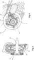
figure 3 shows a cross-section of a detail of the synchronized transmission offigure 1 ; - *
figure 4 shows a longitudinal section of the detail of the synchronized transmission offigure 3 ; - *
figure 5 shows a side raised view of a scooter incorporating the transmission according to the present invention; and - *
figure 6 shows a perspective view of the transmission offigure 1 , closed in the container thereof, and of the related engine block. - By referring to
figures 5 and 6 , a motorcycle, and in particular a scooter, is designated as a whole with 100. The invention relates to the field of the saddle vehicles, or vehicles which are driven astride, in general, having two, three or four wheels, with particular reference to the scooters having a propulsion unit arranged in a position below asaddle 101, inside achassis 102 which herein is represented laterally, extending from afront wheel 103, driven by ahandlebar 104 to a drivingrear wheel 105. - The propulsion unit 106 (
figure 6 ) or, in short, the engine is of the type having one or more cylinders arranged in a tilted position approximatively on the median plane of the vehicle which corresponds to the rotation plane of the two wheels during the rectilinear forward motion. - The
engine 106 has anengine block 107 in one single piece which receives, in the present embodiment, acylinder 108 and a related (not visible) piston. - The piston acting in said
cylinder 108 is connected to a crankshaft 2 positioned transversally and perpendicularly to said median plane. On one represented side (figure 5 and 6 ) of the scooter 100 atransmission device 1 is provided or, more shortly, a transmission of the motion from the crankshaft to the hub of therear wheel 105. - The
transmission 1 has acontainer 109 which receives inside thereof the transmission elements which will be described in greater detail hereinafter. Thecontainer 109 is connected to theengine block 107 by creating a tunnel-like casing including the crankshaft 2 and all transmission elements connected thereto. - Moreover, the
container 109 is closed, on the exposed side of themotorcycle 100, by acover 110 of thetransmission 1, which extends substantially from theengine 106 to the hub shaft of thedriving wheel 105. Thecover 110 is fastened to thecontainer 109 by means ofsuitable bolts 111. Openings, slots, air intakes could be provided to access and/or cool down the transmission elements through saidcover 110. - The
cover 110 is rested upon a fixing edge 112 of thecontainer 109, provided with fixing seats 113 for saidbolts 111 and with additionalfront connection seat 114, with a hinge connection of axis A to allow theengine block 107 and thetransmission 1 to swing, andrear connection seat 115, connected to arear suspension 116, to connect thecasing 109 and thewhole transmission 1 to the frame of thevehicle 100. - Such transmission is of multiple speed type and of
synchronous type 1, and it is arranged for connecting the crankshaft 2, which receives the motion from moving one or more pistons, to the hub shaft, by considering that these two shafts are parallel therebetween and placed at a prefixed distance. The hub shaft, at a distal end thereof, is provided with apinion 5 for connecting to therear wheel 105. - They are both perpendicular to the median plane of the vehicle, defined by the rotation plane of the front and rear wheels. It is further meant that the use of this type of transmission is not limited to the herein represented two-wheel scooter, but it can be extended to a scooter with a pair of front wheels or to four-wheel scooters.
- By referring instead to
figures 1 ,2 ,3 and 4 , a multiple gearbox without thecasing 109 and thecover 110, in particular a transmission with four-speed gearbox, is designated as a whole with 1. It is of the type suitable to be assembled on a motorcycle as transmission element which actuates a driving wheel of themotorcycle 100, in particular a scooter, that is the rear wheel thereof 105. - On this regard, it comprises a crankshaft 2, which is made to rotate by the engine, thereof the
piston rod 30 is represented, and a first driven shaft, that is theprimary shaft 3, and a secondary shaft, which can be connected directly to the wheel or which transmits the rotation, as in the present embodiment, to ahub shaft 5 which is connected to the driving wheel of the vehicle. - It is to be noted that the arrangement of the shafts is so that the crankshaft 2 assumes a position which is substantially parallel to the rotation axis of the driving wheel, that is to the
hub shaft 5. Therefore, this transmission element has the purpose of transferring the motion from an engine, having a crankshaft transversal to the motorcycle, to a wheel having an axis transversal to the vehicle, too. - The passage from secondary shaft to
hub shaft 5 takes place through a pair ofgearwheels - It is to be meant that the
hub shaft 5 could be constituted by the same secondary shaft, provided that one renounces to the above mentioned reduction ratio on the hub and providing to invert the rotation direction of the crankshaft 2. - In the light of what above, in each case the secondary shaft is directly or indirectly connected, from the mechanical point of view, to the driving wheel thereto the gearbox refers.
- The crankshaft 2 and the
primary shaft 3 are substantially parallel and they are connected by transmission elements which allow the motion transmission according to different speed ratios. Such transmission elements include a first group of toothed pulleys assembled on the crankshaft 2, a second group of toothed pulleys assembled at theprimary shaft 3, and a pair of transmission belts extending from the first to the second group of pulleys. - Under transmission belt any flexible annular element is meant apt to transmit the motion between two pulleys offset therebetween, in particular with axes parallel therebetween. The transmission belts then include any kind of belts or chains, the pulleys in case could be toothed to implement a synchronous connection.
- In the present embodiment, as well as in the subsequent ones, the transmission belts advantageously are synchronous transmission belts; under synchronous belt a belt, usually a toothed belt or a roller chain, is meant which transmits the motion from a wheel or toothed pulley to another wheel or toothed pulley with a transmission ratio which is determined by the ratio between the diameters of the wheels, without it is subjected to clutch or sliding losses.
- However, generally, the herein described transmission is of the synchronous or almost synchronous type, and it uses a pair of pulleys connected kinematically by a belt, preferably a toothed belt on toothed pulleys or a high performance belt, for example of the Stretch Fit® type or the like.
- It is to be meant that what described hereinafter can be wholly or partially applied even to an equivalent synchronous transmission of other type, for example a pinion - chain - toothed wheel transmission.
- The absence of sliding portions and/or portions dragged by clutch, typical instead of the gearboxes of CVT (Continuously variable transmission) type, even known as continuous gearboxes or continuous variators, makes the herein described gearbox of synchronous type.
- Therefore, in the present embodiment as well as in the subsequent ones, the above-mentioned pulleys are toothed pulleys, connected by toothed belts, preferably of the type made of rubber.
- On the crankshaft 2 a
main clutch 8 is assembled which, in the present example, is of centrifugal type, well known in the art. In this example, this kind of clutch allows the motion transmission from the crankshaft 2 to the cascaded transmission elements, and it engages automatically at a rotation regime comprised in a prefixed range, for example between 1000 and 2000 revolutions per minute. At a lower rotation regime, theclutch 8 is not engaged and the engine is idle, whereas the driving wheel is not stressed. - However, it is meant that, in particular applications, this type of clutch can be replaced by a manual coupling clutch which is perfectly equivalent, or by a clutch actuated by a servo-mechanism.
- On the crankshaft 2 a
first pulley 9 and asecond pulley 10 are keyed in cascade to saidclutch 8. They are respectively connected, by means of a firstsynchronous belt 11, to athird pulley 12 and, by means of a secondsynchronous belt 13, to afourth pulley 14. - At the front of the crankshaft 2, there is a
first synchronizer 16 for synchronizing thesecond belt 13, that is the connection between second andfourth pulley primary shaft 3 there is asecond synchronizer 17 which synchronizes the toothed wheels keyed on suchprimary shaft 3. - In fact, a first and a second toothed wheel are keyed on the
primary shaft 3 which are engaged, respectively with a third toothed wheel and with a fourth toothed wheel, both keyed on the secondary shaft. The third toothed wheel 20, in this embodiment, is assembled on a second free wheel. - When the
clutch 8 is activated so that it transmits the motion through the crankshaft 2, the twosynchronizers third pulley first belt 11. - At a particular moment, which can be decided by the driver or autonomously set by the system, according to a well precise implemented logic, the system is requested to pass from the first to the second speed and, even in this case, the transmission uses the first
synchronous belt 11. - In this case, however, the second actuated
synchronizer 17, arranged on theprimary shaft 3, is activated, and so it intervenes by synchronizing a pair of toothed wheels assigned to the transmission of the second and of the fourth speed. - At a particular moment, which can be decided by the driver or autonomously set by the system, according to a well precise implemented logic, the system is requested to pass from the second to the third speed and, in this case, the transmission has to use the second
synchronous belt 13. - The
first synchronizer 16 placed onto the crankshaft 2 is activated, by implementing the synchronization of thesecond pulley 10 of the third and of fourth speed. In the latter case, the secondsynchronous belt 13, now placed in motion, transmits the motion to theprimary shaft 3 of the gearbox. As the twobelts primary shaft 3 would have two different speeds set by the transmission, however this is avoided by the presence of a free wheel which allows to disengage thethird pulley 13 related to the first and second speed. - However, in the same moment, on the driven shaft, the second synchronizer 20 on the
primary shaft 3 has to be deactivated, so as to cease the synchronization of the ratio of toothed wheels of second and fourth speed. Therefore, the motion reaches theprimary shaft 3 through the pair of pulleys related to the third and fourth speed, and theprimary shaft 3 rotates with the speed set by the third speed. - It is to be noted that the synchronizer has to be deactivated independently from the rotation speed reached by the respective
primary shaft 3, and this makes that it has to be of actuated type, that is of the type which is actuated or deactivated after an actuation determined by a system decision and not by simply reaching a rotation regime. - As last case the insertion of the fourth speed remains: as to the
first synchronizer 16 on the crankshaft nothing changes with respect to the case of the third speed. In fact, thesecond belt 13 between the second and thefourth pulley - However, for the fourth speed, even the
second synchronizer 17 has to intervene which is actuated on theprimary shaft 3, by synchronizing again a pair of toothed wheels belonging to the second and fourth speed. - By referring to the first synchronizer 16 (
figure 2 ) the structure of the herein described synchronizers, and the operation thereof, is described. - The synchronizer comprises a supporting
plate 21 which has a substantially flared shape, to define a space contained therein; then it has a concavity faced in opposite direction with respect to the transmission elements to be actuated. - Therefore, it extends axially between two planes, a more external one thereat the
plate 21 comprises a wide central opening, and a more internal one having a central hole, thereat it is constrained to transmission elements, in particular to the carter of a gearbox. - It comprises an actuation axis, constituted by a
shaft 53, having aproximal actuation end 22 inserted internally in the central hole of theplate 21. The rotatingshaft 53 extends from the supportingplate 21 in the remaining portion of the transmission elements which will be now described; the axial translation thereof determines the synchronization of a transmission element. - The synchronizer comprises a bell-
like spring 23 which is substantially shaped like a cone, implemented by a metal sheaf wherein through slots are made allowing to deform thespring 23 according to an axial direction. - It has then the shape of a conical disc and the periphery thereof is rested upon the outer edge of the supporting
plate 21, so as to cover wholly said central opening thereof; the conical end of the bell-like spring 23 has a central opening with a circular edge thereon aball bearing 25 is fastened which acts as platform for assembling acam follower 26, fastened outside thespring 23, the function thereof is to translate axially opposed to the elastic resistance offered by thespring 23, so as to interfere with theactuation end 22 of theshaft 53. - The
cam follower 26 is substantially shaped like a disc and the cam profile thereof is formed on the disc face directed outwards, defined on a peripheral circumference arc of thecam 26 and formed by a raised rib. - The disc of the
cam follower 26 forms a plane perpendicular to the synchronization axis, and the cam profile thereof projects perpendicularly from said plane, in axial direction. - A corresponding
cam 29 is associated to the above-mentionedcam follower 26, having a hole wherein anactuation spindle 30 is inserted with a plug connection allowing the rotation of thecam 29 by rotating saidspindle 30, the axis thereof coincides with the axis of theactuation shaft 53. - On the contrary, the
cam follower 26 has a recess faced towards theactuation spindle 30 which constitutes a seat thereof for the distal end thereof. - The
cam 29 comprises a ring apt to couple with saidcam follower 26, on the exposed face thereof a second cam profile is formed which projects axially and which is intended to couple with the cam profile of thecam follower 26. On this regard, it will include a raised cam surface, a lowered cam surface and related tilted connections. - In the light of what above, the above-described
synchronizers - Each
synchronizer cam 29 apt to be rotated by anactuation spindle 30 of thecam 29 which determines the translation of acam follower 26 which in turn interferes with theactuation end 22 of the respective synchronizer. - At the opposite distal end, the
actuation spindle 30 comprises acontrol wheel 36 which is useful to rotate thecam 29 with respect to thecam follower 26, thus determining the translation of thecam 26 and, consequently, of theactuation end 22 and of theshaft 53. - In the present transmission, the
first synchronizer 16 has afirst control wheel 36 which, as it will appear better hereinafter, is a toothed wheel which is dragged in rotation by an electric motor. - Going back to the operation of the synchronizer, a half-rotation of the
cam 29 determines the translation, in one direction or in the other one, of thecam follower 26, of thebearing 25 and of the bell-like spring 23, and then of theactuation end 22. - A first and a
second actuation pulley actuation spindle 30 of eachsynchronizer - The two actuation pulleys 37, 38 are made synchronous by an
actuation belt 39, in particular of filiform type, inserted in the peripheral guides of the actuation pulleys 37, 38. - In this way, the rotation set by the
control wheel 36 to theactuation spindle 30 of thefirst synchronizer 16 will be transmitted even to the actuation spindle of the second synchronizer. - In the light of the above-described operation of the transmission, this synchrony will be so as to determine, in sequence, the activation of the second synchronizer (second speed), followed by the de-activation thereof and by the simultaneous activation of the first synchronizer (third speed), in turn followed by the simultaneous activation of both synchronizers (fourth speed), starting from both de-activated synchronizers (first speed).
- Therefore, the first actuating
pulley 37, connected to anactuation spindle 30 of thecam 29 which is rotated by thecontrol wheel 26, and thesecond actuating pulley 38, connected to theother actuation spindle 30 of thesecond synchronizer 17, are connected by a belt so that the simultaneous rotation thereof is caused by the rotation of saidcontrol wheel 36, each speed corresponding to an angular position of said first and second actuating pulleys 37, 38. - This sequence will be controlled by the rotation of the
control wheel 36, and in particular a step of said sequence will correspond to each rotation angle of 90°. - In this example, the
control wheel 36 is a toothed wheel which is actuated in rotation by means of anelectric motor 40 equipped with atoothed shaft 41 engaged in saidtoothed wheel 36. In particular, this electric motor will be of the type with rotating shaft, which conveniently will be of the screw type. - The
screw shaft 41 is included in acasing 42 which guarantees the position thereof, and it is connected by means of a plug connection to the rotor of theelectric motor 40, the whole being connected to the transmission carter and electrically fed through a control board. - In this example, the
electric motor 40, thescrew shaft thereof 41 and thetoothed control wheel 36 are arranged at the first synchronizer, that is the one arranged at the crankshaft 2 of thetransmission 1, whereas thesecond synchronizer 17 is actuated in cascade through the actuating pulleys, but it is meant that this scheme could be in case overturned without leaving the protective scope of the present invention as defined by the scope of the appended claims. - It is to be further meant that the electric motor could be selected of the most convenient type for this application. It could be driven by a board which replies either to a pre-set operation logic in a wholly automatic gearbox or to a control given by the vehicle's driver.
- By way of example, the electric motor could be of axial type, so as to control in axial translation a control spindle which, in this case, could be a rack.
- To the above-described synchronized transmission a person skilled in the art, with the purpose of satisfying additional and contingent needs, could introduce several additional modifications and variants, however all comprised within the protective scope of the present invention, as defined by the enclosed claims.
Claims (9)
- A multiple speed transmission (1) of a motorcycle, wherein a crankshaft actuated by the engine and a driven shaft, connected to a rear wheel, are substantially parallel and connected therebetween, comprising a first axial actuation synchronizer (16) placed at the front of the crankshaft (2) and a second axial actuation synchronizer (17) arranged at the front of a driven shaft connected to a rear wheel, each synchronizer (16, 17) comprising a respective rotating cam actuator (26, 29) having a cam follower (26) apt to be rotated by a respective cam spindle (30) by determining a translation of the cam follower (26) which interferes with an actuation end (22) of the respective synchronizer (16,17) wherein the transmission (1) further comprises:a toothed control wheel (36), keyed on one of the cam spindles (30), actuated in rotation by means of an electric motor (40) equipped with a toothed shaft (41) engaged in said toothed control wheel (36); and the transmission being characterised by further comprising:a first actuating pulley (37), connected to a cam spindle (30) corresponding to said control wheel (36), and a second actuating pulley (38), connected to the other cam spindle (30), said pulleys (37, 38) being connected by a belt (39) which causes the simultaneous rotation thereof by actuating said control wheel (36), each speed corresponding to an angular position of said first and second actuating pulleys (37, 38).
- The synchronized transmission (1) according to claim 1, wherein each rotating cam actuator has a cam (29) apt to be rotated by an actuation spindle (30) of the cam (29) which determines the translation of a cam follower (26) which in turn interferes with the actuation end (22) of the respective synchronizer (16, 17) in opposition to a spring (3).
- The synchronized transmission (1) according to claim 1, wherein a bearing (25) is provided between cam follower (26) and actuation end (22).
- The synchronized transmission (1) according to claim 1, wherein said first and second actuation pulleys (37, 38) are keyed on the distal end of the cam spindle (30) projecting outside the synchronizer.
- The synchronized transmission (1) according to claim 1, wherein said actuation belt 39 is of filiform type.
- The synchronized transmission (1) according to claim 1, wherein the rotation of the control wheel (36) is arranged so as to determine, in sequence, the activation of the second synchronizer (second speed), followed by the de-activation thereof and by the simultaneous activation of the first synchronizer (third speed), in turn followed by the simultaneous activation of both synchronizers (fourth speed), starting from both de-activated synchronizers (first speed).
- The synchronized transmission (1) according to claim 6, wherein said sequence is controlled by the rotation of the control wheel (36), a step of said sequence corresponding to each rotation angle of 90° thereof.
- The synchronized transmission (1) according to claim 1, wherein the electric motor (40) has a rotating shaft controlling a screw toothed shaft (41).
- A motorcycle (100) comprising a propulsion unit (106) arranged in a position below a saddle (101), inside a chassis (102) extending from a front wheel (103) to rear driving wheel (105), comprising, between said propulsion unit (106) and said rear wheel (105) a transmission (1) according to one or more of the preceding claims, received in a container (109) closed, on an exposed side of the motorcycle (100), by a cover (110).
Applications Claiming Priority (2)
| Application Number | Priority Date | Filing Date | Title |
|---|---|---|---|
| IT102016000122192A IT201600122192A1 (en) | 2016-12-01 | 2016-12-01 | Synchronized transmission |
| PCT/EP2017/081012 WO2018100078A1 (en) | 2016-12-01 | 2017-11-30 | Synchronized transmission |
Publications (3)
| Publication Number | Publication Date |
|---|---|
| EP3548325A1 EP3548325A1 (en) | 2019-10-09 |
| EP3548325B1 true EP3548325B1 (en) | 2023-08-16 |
| EP3548325C0 EP3548325C0 (en) | 2023-08-16 |
Family
ID=58994992
Family Applications (1)
| Application Number | Title | Priority Date | Filing Date |
|---|---|---|---|
| EP17821486.2A Active EP3548325B1 (en) | 2016-12-01 | 2017-11-30 | Synchronized transmission |
Country Status (7)
| Country | Link |
|---|---|
| US (1) | US11292328B2 (en) |
| EP (1) | EP3548325B1 (en) |
| JP (1) | JP7044782B2 (en) |
| CN (1) | CN110214093A (en) |
| IT (1) | IT201600122192A1 (en) |
| TW (1) | TWI751238B (en) |
| WO (1) | WO2018100078A1 (en) |
Families Citing this family (1)
| Publication number | Priority date | Publication date | Assignee | Title |
|---|---|---|---|---|
| CZ2019185A3 (en) * | 2019-03-27 | 2019-12-27 | Dvořák - Svahové Sekačky S.R.O. | Axle, especially for a universal carrier chassis |
Family Cites Families (16)
| Publication number | Priority date | Publication date | Assignee | Title |
|---|---|---|---|---|
| JPH05157163A (en) | 1991-12-03 | 1993-06-22 | Kawasaki Heavy Ind Ltd | Automotive transmission |
| JP2002081534A (en) * | 2000-09-04 | 2002-03-22 | Bando Chem Ind Ltd | Transmission control device for vehicles |
| CN100497998C (en) * | 2003-07-16 | 2009-06-10 | 雅马哈发动机株式会社 | Engine for saddle-riding type vehicle and saddle-riding type vehicle having the same |
| JP4405465B2 (en) * | 2005-12-28 | 2010-01-27 | 本田技研工業株式会社 | Twin clutch device |
| DE102006055798A1 (en) * | 2006-07-28 | 2008-01-31 | Robert Bosch Gmbh | Dual clutch for transferring torque from drive shaft to output shaft, has clutch basket connected with drive shaft, and actuation device exhibiting curve bodies that are concentric to each other and are rotatable against each other |
| JP4767149B2 (en) * | 2006-10-27 | 2011-09-07 | ヤマハ発動機株式会社 | Saddle riding vehicle |
| BRPI0818326B1 (en) * | 2007-10-12 | 2020-09-15 | Tvs Motor Company Limited | TRANSMISSION SYSTEM FOR HYBRID TWO-WHEEL VEHICLE |
| CN201784785U (en) * | 2010-08-27 | 2011-04-06 | 李智光 | Electric motorcycle power device |
| EP2527236B1 (en) * | 2011-05-27 | 2013-07-31 | iwis motorsysteme GmbH & Co. KG | Switchable transmission assembly |
| KR101202832B1 (en) * | 2012-01-27 | 2012-11-21 | 서광모 | Power Transmission Apparatus for Electric Vehicle |
| JP5911782B2 (en) * | 2012-09-28 | 2016-04-27 | 本田技研工業株式会社 | Gearbox type transmission |
| FR3008755B1 (en) * | 2013-07-16 | 2016-11-04 | Renault Sa | COMPACT MECHANICAL CONTROL FOR DOUBLE CLUTCH |
| DE102013021947A1 (en) * | 2013-12-20 | 2015-06-25 | GM Global Technology Operations LLC (n. d. Gesetzen des Staates Delaware) | Manual transmission and clutch assembly for it |
| DE102014003241A1 (en) | 2014-03-10 | 2015-09-10 | GM Global Technology Operations LLC (n. d. Ges. d. Staates Delaware) | manual transmission |
| JP5996701B1 (en) * | 2015-03-30 | 2016-09-21 | 本田技研工業株式会社 | Transmission with synchro mechanism |
| JP6538016B2 (en) * | 2016-09-30 | 2019-07-03 | 本田技研工業株式会社 | Internal combustion engine for straddle type vehicles |
-
2016
- 2016-12-01 IT IT102016000122192A patent/IT201600122192A1/en unknown
-
2017
- 2017-11-30 WO PCT/EP2017/081012 patent/WO2018100078A1/en not_active Ceased
- 2017-11-30 US US16/464,891 patent/US11292328B2/en active Active
- 2017-11-30 EP EP17821486.2A patent/EP3548325B1/en active Active
- 2017-11-30 CN CN201780074668.2A patent/CN110214093A/en active Pending
- 2017-11-30 JP JP2019528793A patent/JP7044782B2/en active Active
- 2017-12-01 TW TW106142188A patent/TWI751238B/en not_active IP Right Cessation
Also Published As
| Publication number | Publication date |
|---|---|
| TWI751238B (en) | 2022-01-01 |
| CN110214093A (en) | 2019-09-06 |
| EP3548325A1 (en) | 2019-10-09 |
| TW201827730A (en) | 2018-08-01 |
| JP2020500768A (en) | 2020-01-16 |
| US11292328B2 (en) | 2022-04-05 |
| US20190389295A1 (en) | 2019-12-26 |
| EP3548325C0 (en) | 2023-08-16 |
| WO2018100078A1 (en) | 2018-06-07 |
| IT201600122192A1 (en) | 2018-06-01 |
| JP7044782B2 (en) | 2022-03-30 |
Similar Documents
| Publication | Publication Date | Title |
|---|---|---|
| EP1956269B1 (en) | Power unit and straddle-type vehicle | |
| US20140349792A1 (en) | Countinuously variable transmission drive pulley | |
| EP3548768B1 (en) | High performance synchronous transmission | |
| CN108603585A (en) | Stepless speed change device with the device for changing shift curve | |
| EP3548325B1 (en) | Synchronized transmission | |
| EP3548376B1 (en) | Synchronized transmission, in particular for motorcycles | |
| US20180223974A1 (en) | Four-speed motorcycle transmission | |
| EP3332155B1 (en) | Three-speed motorcycle transmission | |
| EP3548776B1 (en) | High performance synchronous transmission | |
| WO2018100151A1 (en) | Axial actuation synchronizer | |
| EP3548778B1 (en) | High performance synchronous transmission | |
| US10995823B2 (en) | Power unit for saddled vehicle | |
| EP3548375B1 (en) | High performance synchronous transmission | |
| IT201600122205A1 (en) | Relevant transmission of the report used |
Legal Events
| Date | Code | Title | Description |
|---|---|---|---|
| STAA | Information on the status of an ep patent application or granted ep patent |
Free format text: STATUS: UNKNOWN |
|
| STAA | Information on the status of an ep patent application or granted ep patent |
Free format text: STATUS: THE INTERNATIONAL PUBLICATION HAS BEEN MADE |
|
| PUAI | Public reference made under article 153(3) epc to a published international application that has entered the european phase |
Free format text: ORIGINAL CODE: 0009012 |
|
| STAA | Information on the status of an ep patent application or granted ep patent |
Free format text: STATUS: REQUEST FOR EXAMINATION WAS MADE |
|
| 17P | Request for examination filed |
Effective date: 20190624 |
|
| AK | Designated contracting states |
Kind code of ref document: A1 Designated state(s): AL AT BE BG CH CY CZ DE DK EE ES FI FR GB GR HR HU IE IS IT LI LT LU LV MC MK MT NL NO PL PT RO RS SE SI SK SM TR |
|
| AX | Request for extension of the european patent |
Extension state: BA ME |
|
| DAV | Request for validation of the european patent (deleted) | ||
| DAX | Request for extension of the european patent (deleted) | ||
| STAA | Information on the status of an ep patent application or granted ep patent |
Free format text: STATUS: EXAMINATION IS IN PROGRESS |
|
| 17Q | First examination report despatched |
Effective date: 20210719 |
|
| GRAP | Despatch of communication of intention to grant a patent |
Free format text: ORIGINAL CODE: EPIDOSNIGR1 |
|
| STAA | Information on the status of an ep patent application or granted ep patent |
Free format text: STATUS: GRANT OF PATENT IS INTENDED |
|
| INTG | Intention to grant announced |
Effective date: 20230310 |
|
| GRAS | Grant fee paid |
Free format text: ORIGINAL CODE: EPIDOSNIGR3 |
|
| GRAA | (expected) grant |
Free format text: ORIGINAL CODE: 0009210 |
|
| STAA | Information on the status of an ep patent application or granted ep patent |
Free format text: STATUS: THE PATENT HAS BEEN GRANTED |
|
| AK | Designated contracting states |
Kind code of ref document: B1 Designated state(s): AL AT BE BG CH CY CZ DE DK EE ES FI FR GB GR HR HU IE IS IT LI LT LU LV MC MK MT NL NO PL PT RO RS SE SI SK SM TR |
|
| REG | Reference to a national code |
Ref country code: GB Ref legal event code: FG4D |
|
| REG | Reference to a national code |
Ref country code: CH Ref legal event code: EP |
|
| REG | Reference to a national code |
Ref country code: DE Ref legal event code: R096 Ref document number: 602017072868 Country of ref document: DE |
|
| REG | Reference to a national code |
Ref country code: IE Ref legal event code: FG4D |
|
| U01 | Request for unitary effect filed |
Effective date: 20230913 |
|
| U07 | Unitary effect registered |
Designated state(s): AT BE BG DE DK EE FI FR IT LT LU LV MT NL PT SE SI Effective date: 20230920 |
|
| U20 | Renewal fee for the european patent with unitary effect paid |
Year of fee payment: 7 Effective date: 20231020 |
|
| PG25 | Lapsed in a contracting state [announced via postgrant information from national office to epo] |
Ref country code: GR Free format text: LAPSE BECAUSE OF FAILURE TO SUBMIT A TRANSLATION OF THE DESCRIPTION OR TO PAY THE FEE WITHIN THE PRESCRIBED TIME-LIMIT Effective date: 20231117 |
|
| PG25 | Lapsed in a contracting state [announced via postgrant information from national office to epo] |
Ref country code: IS Free format text: LAPSE BECAUSE OF FAILURE TO SUBMIT A TRANSLATION OF THE DESCRIPTION OR TO PAY THE FEE WITHIN THE PRESCRIBED TIME-LIMIT Effective date: 20231216 |
|
| PG25 | Lapsed in a contracting state [announced via postgrant information from national office to epo] |
Ref country code: RS Free format text: LAPSE BECAUSE OF FAILURE TO SUBMIT A TRANSLATION OF THE DESCRIPTION OR TO PAY THE FEE WITHIN THE PRESCRIBED TIME-LIMIT Effective date: 20230816 Ref country code: NO Free format text: LAPSE BECAUSE OF FAILURE TO SUBMIT A TRANSLATION OF THE DESCRIPTION OR TO PAY THE FEE WITHIN THE PRESCRIBED TIME-LIMIT Effective date: 20231116 Ref country code: IS Free format text: LAPSE BECAUSE OF FAILURE TO SUBMIT A TRANSLATION OF THE DESCRIPTION OR TO PAY THE FEE WITHIN THE PRESCRIBED TIME-LIMIT Effective date: 20231216 Ref country code: HR Free format text: LAPSE BECAUSE OF FAILURE TO SUBMIT A TRANSLATION OF THE DESCRIPTION OR TO PAY THE FEE WITHIN THE PRESCRIBED TIME-LIMIT Effective date: 20230816 Ref country code: GR Free format text: LAPSE BECAUSE OF FAILURE TO SUBMIT A TRANSLATION OF THE DESCRIPTION OR TO PAY THE FEE WITHIN THE PRESCRIBED TIME-LIMIT Effective date: 20231117 |
|
| PG25 | Lapsed in a contracting state [announced via postgrant information from national office to epo] |
Ref country code: PL Free format text: LAPSE BECAUSE OF FAILURE TO SUBMIT A TRANSLATION OF THE DESCRIPTION OR TO PAY THE FEE WITHIN THE PRESCRIBED TIME-LIMIT Effective date: 20230816 |
|
| PG25 | Lapsed in a contracting state [announced via postgrant information from national office to epo] |
Ref country code: ES Free format text: LAPSE BECAUSE OF FAILURE TO SUBMIT A TRANSLATION OF THE DESCRIPTION OR TO PAY THE FEE WITHIN THE PRESCRIBED TIME-LIMIT Effective date: 20230816 |
|
| PG25 | Lapsed in a contracting state [announced via postgrant information from national office to epo] |
Ref country code: SM Free format text: LAPSE BECAUSE OF FAILURE TO SUBMIT A TRANSLATION OF THE DESCRIPTION OR TO PAY THE FEE WITHIN THE PRESCRIBED TIME-LIMIT Effective date: 20230816 Ref country code: RO Free format text: LAPSE BECAUSE OF FAILURE TO SUBMIT A TRANSLATION OF THE DESCRIPTION OR TO PAY THE FEE WITHIN THE PRESCRIBED TIME-LIMIT Effective date: 20230816 Ref country code: ES Free format text: LAPSE BECAUSE OF FAILURE TO SUBMIT A TRANSLATION OF THE DESCRIPTION OR TO PAY THE FEE WITHIN THE PRESCRIBED TIME-LIMIT Effective date: 20230816 Ref country code: CZ Free format text: LAPSE BECAUSE OF FAILURE TO SUBMIT A TRANSLATION OF THE DESCRIPTION OR TO PAY THE FEE WITHIN THE PRESCRIBED TIME-LIMIT Effective date: 20230816 Ref country code: SK Free format text: LAPSE BECAUSE OF FAILURE TO SUBMIT A TRANSLATION OF THE DESCRIPTION OR TO PAY THE FEE WITHIN THE PRESCRIBED TIME-LIMIT Effective date: 20230816 |
|
| PLBE | No opposition filed within time limit |
Free format text: ORIGINAL CODE: 0009261 |
|
| STAA | Information on the status of an ep patent application or granted ep patent |
Free format text: STATUS: NO OPPOSITION FILED WITHIN TIME LIMIT |
|
| REG | Reference to a national code |
Ref country code: CH Ref legal event code: PL |
|
| PG25 | Lapsed in a contracting state [announced via postgrant information from national office to epo] |
Ref country code: MC Free format text: LAPSE BECAUSE OF FAILURE TO SUBMIT A TRANSLATION OF THE DESCRIPTION OR TO PAY THE FEE WITHIN THE PRESCRIBED TIME-LIMIT Effective date: 20230816 |
|
| PG25 | Lapsed in a contracting state [announced via postgrant information from national office to epo] |
Ref country code: CH Free format text: LAPSE BECAUSE OF NON-PAYMENT OF DUE FEES Effective date: 20231130 |
|
| 26N | No opposition filed |
Effective date: 20240517 |
|
| GBPC | Gb: european patent ceased through non-payment of renewal fee |
Effective date: 20231130 |
|
| PG25 | Lapsed in a contracting state [announced via postgrant information from national office to epo] |
Ref country code: MC Free format text: LAPSE BECAUSE OF FAILURE TO SUBMIT A TRANSLATION OF THE DESCRIPTION OR TO PAY THE FEE WITHIN THE PRESCRIBED TIME-LIMIT Effective date: 20230816 Ref country code: CH Free format text: LAPSE BECAUSE OF NON-PAYMENT OF DUE FEES Effective date: 20231130 |
|
| REG | Reference to a national code |
Ref country code: IE Ref legal event code: MM4A |
|
| PG25 | Lapsed in a contracting state [announced via postgrant information from national office to epo] |
Ref country code: IE Free format text: LAPSE BECAUSE OF NON-PAYMENT OF DUE FEES Effective date: 20231130 |
|
| PG25 | Lapsed in a contracting state [announced via postgrant information from national office to epo] |
Ref country code: GB Free format text: LAPSE BECAUSE OF NON-PAYMENT OF DUE FEES Effective date: 20231130 |
|
| PG25 | Lapsed in a contracting state [announced via postgrant information from national office to epo] |
Ref country code: IE Free format text: LAPSE BECAUSE OF NON-PAYMENT OF DUE FEES Effective date: 20231130 Ref country code: GB Free format text: LAPSE BECAUSE OF NON-PAYMENT OF DUE FEES Effective date: 20231130 |
|
| U20 | Renewal fee for the european patent with unitary effect paid |
Year of fee payment: 8 Effective date: 20241126 |
|
| PG25 | Lapsed in a contracting state [announced via postgrant information from national office to epo] |
Ref country code: CY Free format text: LAPSE BECAUSE OF FAILURE TO SUBMIT A TRANSLATION OF THE DESCRIPTION OR TO PAY THE FEE WITHIN THE PRESCRIBED TIME-LIMIT; INVALID AB INITIO Effective date: 20171130 |
|
| PG25 | Lapsed in a contracting state [announced via postgrant information from national office to epo] |
Ref country code: HU Free format text: LAPSE BECAUSE OF FAILURE TO SUBMIT A TRANSLATION OF THE DESCRIPTION OR TO PAY THE FEE WITHIN THE PRESCRIBED TIME-LIMIT; INVALID AB INITIO Effective date: 20171130 |
|
| PG25 | Lapsed in a contracting state [announced via postgrant information from national office to epo] |
Ref country code: TR Free format text: LAPSE BECAUSE OF FAILURE TO SUBMIT A TRANSLATION OF THE DESCRIPTION OR TO PAY THE FEE WITHIN THE PRESCRIBED TIME-LIMIT Effective date: 20230816 |
|
| U20 | Renewal fee for the european patent with unitary effect paid |
Year of fee payment: 9 Effective date: 20251127 |