EP3548203B1 - Caterpillar casting method of casting a product from liquid metal - Google Patents
Caterpillar casting method of casting a product from liquid metal Download PDFInfo
- Publication number
- EP3548203B1 EP3548203B1 EP17811506.9A EP17811506A EP3548203B1 EP 3548203 B1 EP3548203 B1 EP 3548203B1 EP 17811506 A EP17811506 A EP 17811506A EP 3548203 B1 EP3548203 B1 EP 3548203B1
- Authority
- EP
- European Patent Office
- Prior art keywords
- caterpillar
- casting
- actuator
- relative
- control device
- Prior art date
- Legal status (The legal status is an assumption and is not a legal conclusion. Google has not performed a legal analysis and makes no representation as to the accuracy of the status listed.)
- Active
Links
- 238000005266 casting Methods 0.000 title claims description 68
- 238000000034 method Methods 0.000 title claims description 16
- 229910001338 liquidmetal Inorganic materials 0.000 title claims description 13
- 238000001816 cooling Methods 0.000 claims description 19
- 239000000463 material Substances 0.000 claims description 11
- 230000001105 regulatory effect Effects 0.000 claims description 6
- 230000004913 activation Effects 0.000 claims 1
- 239000011324 bead Substances 0.000 description 13
- 238000004519 manufacturing process Methods 0.000 description 6
- 238000011161 development Methods 0.000 description 4
- 230000018109 developmental process Effects 0.000 description 4
- 229910052751 metal Inorganic materials 0.000 description 3
- 239000002184 metal Substances 0.000 description 3
- 229910000838 Al alloy Inorganic materials 0.000 description 2
- 230000003213 activating effect Effects 0.000 description 2
- 229910052782 aluminium Inorganic materials 0.000 description 2
- XAGFODPZIPBFFR-UHFFFAOYSA-N aluminium Chemical compound [Al] XAGFODPZIPBFFR-UHFFFAOYSA-N 0.000 description 2
- 230000001276 controlling effect Effects 0.000 description 2
- 230000005484 gravity Effects 0.000 description 2
- 230000001360 synchronised effect Effects 0.000 description 2
- 239000002826 coolant Substances 0.000 description 1
- 230000001419 dependent effect Effects 0.000 description 1
- 239000007788 liquid Substances 0.000 description 1
Images


Classifications
-
- B—PERFORMING OPERATIONS; TRANSPORTING
- B22—CASTING; POWDER METALLURGY
- B22D—CASTING OF METALS; CASTING OF OTHER SUBSTANCES BY THE SAME PROCESSES OR DEVICES
- B22D11/00—Continuous casting of metals, i.e. casting in indefinite lengths
- B22D11/06—Continuous casting of metals, i.e. casting in indefinite lengths into moulds with travelling walls, e.g. with rolls, plates, belts, caterpillars
- B22D11/0608—Continuous casting of metals, i.e. casting in indefinite lengths into moulds with travelling walls, e.g. with rolls, plates, belts, caterpillars formed by caterpillars
-
- B—PERFORMING OPERATIONS; TRANSPORTING
- B22—CASTING; POWDER METALLURGY
- B22D—CASTING OF METALS; CASTING OF OTHER SUBSTANCES BY THE SAME PROCESSES OR DEVICES
- B22D11/00—Continuous casting of metals, i.e. casting in indefinite lengths
- B22D11/16—Controlling or regulating processes or operations
- B22D11/168—Controlling or regulating processes or operations for adjusting the mould size or mould taper
Definitions
- the invention relates to a method for producing a cast material from liquid metal according to the preamble of claim 1.
- horizontal ingot casting machines are known, in particular for the production of aluminum alloys, which work in the manner of a rotating caterpillar casting machine.
- a casting machine is, for example, off EP 1 704 005 B1 or WO 95/27145 known.
- the cooling elements of the casting machine on the straight sections or runs of casting beads arranged opposite one another form the wall of a moving casting mold.
- the casting beads each consist of a large number of endlessly interconnected cooling blocks that are transported along the orbits of the beads.
- the cooling blocks are mounted on support elements that are placed on chains and are thus articulated like links in a chain.
- this ingot casting machine comprises a spindle lifting device which is in operative connection with the four corner areas of the ingot casting machine.
- measuring cells and dial gauges are installed when the spindle lifting device is used.
- the disadvantage here is that the servomotors or actuators of the spindle lifting device are not synchronized, that defined positions for the casting beads cannot be repeatedly approached, that no active influence on the casting gap is possible, and that long set-up times are required to open the unit formed from the casting beads to set a new operating state.
- a Another disadvantage is that a position of the casting beads relative to one another cannot be controlled exactly, with automation by means of a control / regulating concept likewise not being given.
- the invention is based on the object of optimizing a method for producing a cast material from liquid metal with regard to the variability of the production process.
- the present invention provides a method of making a cast from liquid metal.
- the liquid metal is poured into a moving casting mold which is formed between cooling blocks which are attached to support elements which are moved in a transport direction along two oppositely arranged endless horizontal circulating tracks.
- the inclination of a unit formed from the upper and lower bead is set relative to the horizontal, in particular during casting, in that at least one actuator, which is operatively connected to the unit formed from the upper and lower bead, is controlled .
- the inclination of either the upper or the lower caterpillar is changed in the direction of its longitudinal axis relative to the respective other caterpillar by at least one actuator, which is connected to a frame device, on one of which is an endless one for this caterpillar Orbit forming guide rail is attached, is operatively connected, is controlled.
- the at least one actuator is controlled by a control device.
- the transport direction in which the support elements with the cooling blocks attached to them are moved along the respective guide rails and the thereby formed orbits is synonymous with the casting direction in which the liquid metal enters the moving casting mold between the cooling blocks is formed in the straight sections of the opposite horizontal orbits, is potted.
- the mentioned adjustment of the unit formed from the caterpillars or at least one caterpillar relative to the other caterpillar with regard to its inclination is achieved by controlling at least one actuator which is operatively connected to a frame device on which the guide rails assigned to the caterpillars are attached.
- the at least one actuator is force-regulated by means of the control device as a function of at least one predetermined process variable, this process variable being a contact force of the upper bead with a lateral guide device.
- the invention is based on the essential knowledge that by controlling the at least one actuator a reproducible setting for the caterpillar casting machine is possible, namely with regard to the inclination of either the unit formed from the upper and lower caterpillars relative to the horizontal or one caterpillar relative to the other Caterpillar.
- An adjustment or change of the inclination of the complete unit formed from the upper and lower bead in its inclination relative to the horizontal can take place in particular during casting, ie at the beginning of a casting process. This allows the flow rate of the liquid metal within the casting mold to be regulated.
- a greater "slope" is created for the moving casting mold in or along the transport direction, because the outlet area of the casting mold is arranged higher than its Inlet area.
- the outlet area of the To pivot the casting mold downwards so that gravity contributes to bringing the liquid cast material into the casting machine or its moving casting mold. This allows the heat transfer from the cast material to the mold, ie to the cooling blocks and thus the temperature control of the cast material or one of it generated bands are affected.
- Such a change in the inclination of the unit formed from the upper and lower bead can also take place automatically during the casting process.
- the inclination of only one caterpillar is variable or adjusted relative to the other caterpillar. In this way, either an exact plane parallelism of the two caterpillars can be achieved on their opposite strands, or a specifically wedge-shaped cast strip profile can be set.
- this actuator can be actuated by an electric motor, pneumatically or hydraulically.
- the at least one actuator can be position-regulated by means of the control device as a function of at least one predetermined process variable.
- This predetermined process variable can be selected from the group formed in particular from the product temperature, the wear of the machine components involved, the type of metal being cast, the speed of the caterpillars, the selected casting thickness and / or the casting width of the cast material.
- the at least one actuator can be force-regulated by means of the control device as a function of a further predetermined process variable, this process variable being formed from the cast metal type.
- a model is stored in the control device by means of which the at least one actuator is controlled.
- automation for the control of the at least one actuator is also possible during the casting process in order to change the inclination either of one caterpillar relative to the other caterpillar, or of the unit formed from both caterpillars.
- an electrically synchronized setting of the caterpillar (s) can take place on the basis of a stored model, which makes it possible to position a caterpillar in any direction in a targeted manner and to move to a position defined for this purpose more easily.
- a caterpillar casting machine 10 and their components explained, which are required for a method according to the invention for producing a cast material 11 (cf. Fig. 2 ) made of liquid metal, in particular aluminum, is used.
- a cast material 11 cf. Fig. 2
- the same features in the drawing are each provided with the same reference symbols. At this point, it is pointed out separately that the drawing is only shown in a simplified manner and, in particular, without a scale.
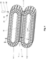
- the caterpillar casting machine 10 comprises an upper, first guide rail 12.1 and a lower, second guide rail 12.2. With these guide rails 12.1, 12.2 two oppositely arranged endless horizontal circulating tracks U for the caterpillar casting machine 10 are formed. A plurality of support elements 14 with cooling blocks 16 attached to them are guided along each guide rail 12 in such a way that a continuous chain of support elements 14 is formed, which is moved or transported in a transport direction T along the guide rails 16. To illustrate the operation of the present invention are in Fig. 1 only two support elements 14 with cooling blocks 16 attached to them are shown on each of the two guide rails 12.
- Fig. 1 shows that a casting mold 18 is formed between the cooling blocks 16, which come into opposition in the straight sections of the circumferential paths U formed by the guide rails 12.
- this casting mold 15 is a casting mold moving in the transport direction T.
- Fig. 2 shows a simplified side view of the caterpillar casting machine 10, in which the guide rails 12.1, 12.2 of Fig. 1 can be used.
- the caterpillar casting machine 10 comprises an upper caterpillar 14.1 and a lower caterpillar 14.2 which - as already explained above - are each formed from a plurality of support elements 14 and cooling blocks 16 attached to them, which run along the orbits U formed by the guide rails 14 in the transport direction T be moved.
- the caterpillars 14.1, 14.2 are each driven by drive wheels 13 which ensure a movement of the support elements 14 and the cooling blocks 16 attached to them around the orbits U.
- Liquid metal for example aluminum or an aluminum alloy
- a pouring nozzle 19 which is elongated and protrudes with its front end into the casting mold 18.
- a casting 11 is produced which - in the right-hand area of FIG Fig. 2 indicated - downstream of the caterpillars 14.1, 14.2 emerges from the casting gap 18 and is then fed to processing (not shown).
- Cooling of the cooling blocks 16 during the casting process is ensured by cooling devices (not shown). By means of these cooling devices, a cooling medium can be applied or sprayed onto the respective cooling blocks.
- the Fig. 3 shows a basically simplified side view of the two caterpillars 14.1, 14.2 of Fig. 2 .
- the transport direction T - seen in the plane of the drawing - is indicated from left to right, an inlet area of the moving casting mold 18 being symbolized by "E” and an outlet area of the casting mold 18 being symbolized by "A”.
- an actuator 26 (top right in the image area) is shown in principle in a simplified manner.
- Such an actuator 26 is used to adjust the inclination of either one caterpillar 14.1, 14.2 relative to the other caterpillar, or the inclination of a unit formed by the two caterpillars 14.1, 14.2 relative to the horizontal.
- the actuator 26 comprises an actuator 27 which is connected to a frame device 22 and to that extent is in operative connection therewith.
- guide rails 12.1, 12.2 are attached for the upper caterpillar 14.1 and lower caterpillar 14.2 (cf. Fig. 1, Fig. 2 ).
- the caterpillar casting machine 10 comprises a control device 28, which is shown in Fig. 2 is symbolized simplified by a rectangle.
- a total of four actuators 26 can be provided, which are operatively connected to the frame device 22 on which, for example, the guide rail 12.1 for the upper caterpillar 14.1 is attached.
- the actuators 26 can be attached to a (in Fig. 3 not shown) machine frame or the like be attached.
- the actuator 26 which is shown in the image area at the top right by a rectangle, the other three actuators simplified only symbolized by an "X", these actuators in the same way with their actuator 27 with the frame device 22 that of the upper caterpillar 14.1 is assigned, are operatively connected.
- the guide rail 12.2 for the lower caterpillar 14.1 can be fixedly attached to a machine frame (not shown).
- Deviating from the representation according to Fig. 3 it is also possible to provide a number of actuators 26 that is greater than or less than four.
- FIG. 4 Another embodiment of the track caster 10 is shown.
- the guide rails 12.1, 12.2 for the upper and lower caterpillars 14.1, 14.2 are attached to a common frame device 22, this frame device 22 being rotatably mounted on a machine frame 24 via a swivel joint 23.
- At least one actuator 26 is operatively connected with its actuator 27 to the frame device 22.
- a position of the frame device 22, and thus also a unit formed from the two caterpillars 14.1, 14.2 can be adjusted when the actuator 26 is actuated, for example with regard to an inclination relative to the horizontal.
- a position of the two caterpillars 14.1, 14.2 can be changed by activating the actuators 26 in such a way that - as shown - the outlet area A of the casting mold 18 (shown on the right in the image area) is lowered or downwards compared to the inlet area E of the casting mold 18 is pivoted.
- FIG Fig. 3 and Fig. 4 a combination of the embodiments of FIG Fig. 3 and Fig. 4 is possible.
- the first and second caterpillars 14.1, 14.2 can be attached to a common frame device 22.
- one of the two caterpillars for example the upper one
- the caterpillar 14.1 with its associated guide rail 12.1 and a frame device 22 attached to it, can be individually operatively connected to further actuators 26, so that this caterpillar 14.1 can be changed in its position relative to the other caterpillar 14.2.
Description
Die Erfindung betrifft ein Verfahren zum Herstellen eines Gießguts aus flüssigem Metall nach dem Oberbegriff von Anspruch 1.The invention relates to a method for producing a cast material from liquid metal according to the preamble of claim 1.
Nach dem Stand der Technik sind insbesondere zur Herstellung von Aluminiumlegierungen Horizontal-Blockgießmaschinen bekannt, die nach Art einer umlaufenden Raupengießmaschine funktionieren. Eine solche Gießmaschine ist z.B. aus
Bei einer herkömmlichen Horizontal-Blockgießmaschine kann die Neigung einer Einheit bestehend aus der oberen und unteren Gießraupe relativ zur Horizontalen eingestellt bzw. verändert werden. Hierzu umfasst diese Blockgießmaschine eine Spindelhubvorrichtung, die mit den vier Eckbereichen der Blockgießmaschine in Wirkverbindung steht. Zur Ausrichtung der aus den Gießraupen gebildeten Einheit sind beim Einsatz der Spindelhubvorrichtung Messdosen und Messuhren installiert. Nachteilig hierbei ist, dass die Stellmotoren bzw. Aktuatoren der Spindelhubvorrichtung nicht synchronisiert sind, dass definierte Positionen für die Gießraupen nicht wiederholt angefahren werden können, dass keine aktive Gießspaltbeeinflussung möglich ist, und dass lange Rüstzeiten erforderlich sind, um die aus den Gießraupen gebildete Einheit auf einen neuen Betriebszustand einzustellen. Ein weiterer Nachteil besteht darin, dass eine Lage der Gießraupen relativ zueinander nicht exakt angesteuert werden kann, wobei eine Automatisierung mittels eines Steuer-/Regelkonzepts ebenfalls nicht gegeben ist.In a conventional horizontal ingot casting machine, the inclination of a unit consisting of the upper and lower casting bead can be adjusted or changed relative to the horizontal. For this purpose, this ingot casting machine comprises a spindle lifting device which is in operative connection with the four corner areas of the ingot casting machine. To align the unit formed from the casting beads, measuring cells and dial gauges are installed when the spindle lifting device is used. The disadvantage here is that the servomotors or actuators of the spindle lifting device are not synchronized, that defined positions for the casting beads cannot be repeatedly approached, that no active influence on the casting gap is possible, and that long set-up times are required to open the unit formed from the casting beads to set a new operating state. A Another disadvantage is that a position of the casting beads relative to one another cannot be controlled exactly, with automation by means of a control / regulating concept likewise not being given.
Aus
In
Entsprechend liegt der Erfindung die Aufgabe zugrunde, ein Verfahren zum Herstellen eines Gießguts aus flüssigem Metall hinsichtlich einer Variabilität des Herstellungsprozesses zu optimieren.Accordingly, the invention is based on the object of optimizing a method for producing a cast material from liquid metal with regard to the variability of the production process.
Diese Aufgabe wird durch ein Verfahren mit den in Anspruch 1 angegebenen Merkmalen gelöst. Vorteilhafte Weiterbildungen der Erfindung sind in dem abhängigen Anspruch definiert.This object is achieved by a method with the features specified in claim 1. Advantageous developments of the invention are defined in the dependent claim.
Die vorliegende Erfindung sieht ein Verfahren zum Herstellen eines Gießguts aus flüssigem Metall vor. Hierbei wird das flüssige Metall in eine sich bewegende Gießform vergossen, die zwischen Kühlblöcken, die an entlang von jeweils zwei gegenüberliegend angeordneten endlosen horizontalen Umlaufbahnen in einer Transportrichtung bewegten Tragelementen angebracht sind, gebildet ist. Gemäß einer Variante dieses Verfahrens ist vorgesehen, dass die Neigung einer Einheit gebildet aus der oberen und unteren Raupe relativ zur Horizontalen insbesondere beim Angießen eingestellt wird, indem zumindest ein Aktuator, der mit der aus der oberen und unteren Raupe gebildeten Einheit wirkverbunden ist, angesteuert wird. Nach einer alternativen Variante des Verfahrens ist vorgesehen, dass die Neigung entweder der oberen oder der unteren Raupe in Richtung ihre Längsachse relativ zu der jeweils anderen Raupe verändert wird, indem zumindest ein Aktuator, der mit einer Rahmeneinrichtung, an der eine für diese Raupe eine endlose Umlaufbahn bildende Führungsschiene angebracht ist, wirkverbunden ist, angesteuert wird. Die Ansteuerung des zumindest einen Aktuator erfolgt durch eine Steuerungseinrichtung.The present invention provides a method of making a cast from liquid metal. In this case, the liquid metal is poured into a moving casting mold which is formed between cooling blocks which are attached to support elements which are moved in a transport direction along two oppositely arranged endless horizontal circulating tracks. According to a variant of this method it is provided that the inclination of a unit formed from the upper and lower bead is set relative to the horizontal, in particular during casting, in that at least one actuator, which is operatively connected to the unit formed from the upper and lower bead, is controlled . According to an alternative variant of the method, it is provided that the inclination of either the upper or the lower caterpillar is changed in the direction of its longitudinal axis relative to the respective other caterpillar by at least one actuator, which is connected to a frame device, on one of which is an endless one for this caterpillar Orbit forming guide rail is attached, is operatively connected, is controlled. The at least one actuator is controlled by a control device.
Im Sinne der vorliegenden Erfindung ist die Transportrichtung, in der die Tragelemente mit den daran angebrachten Kühlblöcken entlang der jeweiligen Führungsschienen und der hierdurch ausgebildeten Umlaufbahnen bewegt werden, gleichbedeutend mit der Gießrichtung, in der das flüssige Metall in die sich bewegende Gießform, die zwischen den Kühlblöcken in den geraden Abschnitten der gegenüberliegenden horizontalen Umlaufbahnen gebildet wird, vergossen wird.In the context of the present invention, the transport direction in which the support elements with the cooling blocks attached to them are moved along the respective guide rails and the thereby formed orbits is synonymous with the casting direction in which the liquid metal enters the moving casting mold between the cooling blocks is formed in the straight sections of the opposite horizontal orbits, is potted.
Die genannte Verstellung der aus den Raupen gebildeten Einheit oder zumindest einer Raupe relativ zur jeweils anderen Raupe bezüglich ihrer Neigung wird durch die Ansteuerung zumindest eines Aktuators erreicht, der mit einer Rahmeneinrichtung, an der die den Raupen zugeordneten Führungsschienen angebracht sind, wirkverbunden ist. Der zumindest eine Aktuator wird mittels der Steuerungseinrichtung in Abhängigkeit von zumindest einer vorbestimmten Prozessgröße kraftgeregelt, wobei diese Prozessgröße eine Kontaktkraft der oberen Raupe zu einer seitlichen Führungseinrichtung ist.The mentioned adjustment of the unit formed from the caterpillars or at least one caterpillar relative to the other caterpillar with regard to its inclination is achieved by controlling at least one actuator which is operatively connected to a frame device on which the guide rails assigned to the caterpillars are attached. The at least one actuator is force-regulated by means of the control device as a function of at least one predetermined process variable, this process variable being a contact force of the upper bead with a lateral guide device.
Der Erfindung liegt die wesentliche Erkenntnis zugrunde, dass durch eine Ansteuerung des zumindest einen Aktuators eine reproduzierbare Einstellung für die Raupengießmaschine möglich ist, nämlich hinsichtlich der Neigung entweder der aus der oberen und unteren Raupe gebildeten Einheit relativ zur Horizontalen, oder einer Raupe relativ zur jeweils anderen Raupe. Eine Verstellung bzw. Veränderung der Neigung der kompletten Einheit gebildet aus der oberen und unteren Raupe in ihrer Neigung relativ zur Horizontalen kann insbesondere beim Angießen, d.h. beim Beginn eines Gießprozesses, erfolgen. Hierdurch kann die Strömungsgeschwindigkeit des flüssigen Metalls innerhalb der Gießform reguliert werden. Beispielsweise kann durch ein Anheben des hinteren Bereichs der beiden Raupen, d.h. im Auslaufbereich der Gießform, erreicht werden, dass für die sich bewegende Gießform in bzw. entlang der Transportrichtung eine größere "Steigung" entsteht, weil der Auslaufbereich der Gießform höher angeordnet ist als deren Einlaufbereich. Alternativ hierzu kann zu Beginn des Gießvorgangs vorgesehen sein, den Auslaufbereich der Gießform nach unten zu schwenken, so dass die Schwerkraft dazu beiträgt, das flüssige Gießgut in die Gießmaschine bzw. deren sich bewegende Gießform zu bringen Hierdurch kann der Wärmeübergang vom Gießgut zur Kokille, d.h. zu den Kühlblöcken und somit die Temperaturführung des Gießguts bzw. eines daraus erzeugten Bands beeinflusst werden. Eine solche Veränderung der Neigung der Einheit gebildet aus der oberen und unteren Raupe kann auch automatisiert während des Gießprozesses erfolgen.The invention is based on the essential knowledge that by controlling the at least one actuator a reproducible setting for the caterpillar casting machine is possible, namely with regard to the inclination of either the unit formed from the upper and lower caterpillars relative to the horizontal or one caterpillar relative to the other Caterpillar. An adjustment or change of the inclination of the complete unit formed from the upper and lower bead in its inclination relative to the horizontal can take place in particular during casting, ie at the beginning of a casting process. This allows the flow rate of the liquid metal within the casting mold to be regulated. For example, by lifting the rear area of the two caterpillars, ie in the outlet area of the casting mold, a greater "slope" is created for the moving casting mold in or along the transport direction, because the outlet area of the casting mold is arranged higher than its Inlet area. Alternatively, it can be provided at the beginning of the casting process, the outlet area of the To pivot the casting mold downwards so that gravity contributes to bringing the liquid cast material into the casting machine or its moving casting mold. This allows the heat transfer from the cast material to the mold, ie to the cooling blocks and thus the temperature control of the cast material or one of it generated bands are affected. Such a change in the inclination of the unit formed from the upper and lower bead can also take place automatically during the casting process.
Ergänzend und/oder alternativ kann vorgesehen sein, dass die Neigung nur einer Raupe relativ zur jeweils anderen Raupe veränderlich ist bzw. verstellt wird. Hierdurch kann entweder eine exakte Planparallelität der beiden Raupen an ihren gegenüberliegenden Trums erreicht werden, oder auch ein gezielt keilförmiges Gussbandprofil eingestellt werden.In addition and / or as an alternative, it can be provided that the inclination of only one caterpillar is variable or adjusted relative to the other caterpillar. In this way, either an exact plane parallelism of the two caterpillars can be achieved on their opposite strands, or a specifically wedge-shaped cast strip profile can be set.
Die vorstehend genannten Möglichkeiten, entweder die Neigung einer aus den beiden Raupen gebildeten Einheit relativ gegenüber der Horizontalen und/oder die Neigung einer der beiden Raupen relativ zur jeweils anderen Raupe gezielt zu verändern, verbessert die Einstellbarkeit des Gießspalts bzw. der zwischen den beiden Raupen bewegten Gießform. In Folge dessen wird das Gussprofil optimiert und eine Reproduzierbarkeit der Qualität (Profil) des Gießguts erreicht. Des Weiteren wird durch eine Automatisierung der genannten Verstell-Funktionen eine Verkürzung der Rüstzeiten erreicht und eine Handhabung der Anlage erleichtert.The aforementioned possibilities of changing either the inclination of a unit formed from the two caterpillars relative to the horizontal and / or the inclination of one of the two caterpillars relative to the other caterpillar improves the adjustability of the casting gap or that moved between the two caterpillars Casting mold. As a result, the cast profile is optimized and the quality (profile) of the cast material can be reproduced. Furthermore, by automating the mentioned adjustment functions, the set-up times are shortened and handling of the system is made easier.
Im Zusammenhang damit, dass eine Steuerungseinrichtung vorgesehen ist, mittels welcher der zumindest eine Aktuator angesteuert werden kann, kann eine Betätigung dieses Aktuators elektromotorisch, pneumatisch oder hydraulisch erfolgen.In connection with the fact that a control device is provided by means of which the at least one actuator can be controlled, this actuator can be actuated by an electric motor, pneumatically or hydraulically.
In vorteilhafter Weiterbildung der Erfindung kann der zumindest eine Aktuator mittels der Steuerungseinrichtung in Abhängigkeit von zumindest einer vorbestimmten Prozessgröße positionsgeregelt werden. Diese vorbestimmte Prozessgröße kann gewählt sein aus der Gruppe gebildet aus insbesondere der Produkttemperatur, dem Verschleiß beteiligter Maschinenkomponenten, der Sorte des vergossenen Metalls, einer Umlaufgeschwindigkeit der Raupen, der gewählten Gießdicke und/oder der Gießbreite des Gießguts.In an advantageous development of the invention, the at least one actuator can be position-regulated by means of the control device as a function of at least one predetermined process variable. This predetermined process variable can be selected from the group formed in particular from the product temperature, the wear of the machine components involved, the type of metal being cast, the speed of the caterpillars, the selected casting thickness and / or the casting width of the cast material.
In vorteilhafter Weiterbildung der Erfindung kann der zumindest eine Aktuator mittels der Steuerungseinrichtung in Abhängigkeit von einer weiteren vorbestimmten Prozessgröße kraftgeregelt sein, wobei diese Prozessgröße aus der vergossenen Metallsorte gebildet ist.In an advantageous development of the invention, the at least one actuator can be force-regulated by means of the control device as a function of a further predetermined process variable, this process variable being formed from the cast metal type.
In vorteilhafter Weiterbildung der Erfindung kann vorgesehen sein, dass in der Steuerungseinrichtung, mittels welcher der zumindest eine Aktuator angesteuert wird, ein Modell hinterlegt ist. Auf Grundlage dieses Modells ist eine Automatisierung für die Ansteuerung des zumindest einen Aktuators auch während des Gießprozesses möglich, um damit die Neigung entweder von einer Raupe relativ zur jeweils anderen Raupe, oder aber der aus beiden Raupen gebildeten Einheit zu verändern. Beispielsweise kann auf Grundlage eines hinterlegten Modells eine elektrisch synchronisierte Einstellung der Raupe(n) erfolgen, wodurch es möglich ist, eine Raupe in jedweder Richtung gezielt anzustellen und eine hierfür definierte Position einfacher anzufahren.In an advantageous development of the invention, it can be provided that a model is stored in the control device by means of which the at least one actuator is controlled. On the basis of this model, automation for the control of the at least one actuator is also possible during the casting process in order to change the inclination either of one caterpillar relative to the other caterpillar, or of the unit formed from both caterpillars. For example, an electrically synchronized setting of the caterpillar (s) can take place on the basis of a stored model, which makes it possible to position a caterpillar in any direction in a targeted manner and to move to a position defined for this purpose more easily.
Nachstehend ist eine bevorzugte Ausführungsform der Erfindung anhand einer schematisch vereinfachten Zeichnung im Detail beschrieben.A preferred embodiment of the invention is described in detail below with reference to a schematically simplified drawing.
Es zeigen:
- Fig. 1
- eine Seitenansicht von zwei Führungsschienen, mit denen zwei gegenüberliegend angeordnete endlose Umlaufbahnen für eine Raupengießmaschine gebildet werden,
- Fig. 2
- eine Seitenansicht einer Raupengießmaschine, deren endlose Umlaufbahnen durch die Führungsschienen von
Fig. 1 gebildet sind, - Fig. 3
- eine Seitenansicht einer oberen und unteren Raupe der Raupengießmaschine von
Fig. 2 , und - Fig. 4
- eine Seitenansicht einer oberen und unteren Raupe der Raupengießmaschine von
Fig. 2 .
- Fig. 1
- a side view of two guide rails with which two oppositely arranged endless revolving tracks for a caterpillar caster are formed,
- Fig. 2
- a side view of a caterpillar caster whose endless orbits through the guide rails of
Fig. 1 are formed - Fig. 3
- FIG. 8 is a side view of upper and lower tracks of the track caster of FIG
Fig. 2 , and - Fig. 4
- FIG. 8 is a side view of upper and lower tracks of the track caster of FIG
Fig. 2 .
Nachstehend sind unter Bezugnahme auf die
Ausweislich der Seitenansicht von
Eine Kühlung der Kühlblöcke 16 während des Gießprozesses ist durch (nicht gezeigte) Kühleinrichtungen gewährleistet. Mittels dieser Kühleinrichtungen kann ein Kühlmedium auf die jeweiligen Kühlblöcke ausgebracht bzw. gespritzt werden.Cooling of the cooling blocks 16 during the casting process is ensured by cooling devices (not shown). By means of these cooling devices, a cooling medium can be applied or sprayed onto the respective cooling blocks.
Die
In der
Bei der Ausführungsform von
Unter Bezugnahme auf die Transportrichtung T (in der
Abweichend von der Darstellung gemäß
In der
Bezüglich der Ausführungsform von
Bei den Ausführungsformen nach den
Schließlich darf darauf hingewiesen werden, dass für die Raupengießmaschine 10 auch eine Kombination der Ausführungsformen von
- 1010
- RaupengießmaschineCaterpillar caster
- 1111
- GießgutCast material
- 1212th
- FührungsschienenGuide rails
- 12.112.1
- erste (obere) Führungsschienefirst (upper) guide rail
- 12.212.2
- zweite (untere) Führungsschienesecond (lower) guide rail
- 1313th
- Antriebsraddrive wheel
- 1414th
- TragelementSupport element
- 14.114.1
- erste (obere) Raupefirst (upper) caterpillar
- 14.214.2
- zweite (untere) Raupesecond (lower) caterpillar
- 1616
- KühlblockCooling block
- 1818th
- GießformCasting mold
- 1919th
- GießdüsePouring nozzle
- 2020th
- Behältercontainer
- 2222nd
- RahmeneinrichtungFrame equipment
- 2323
- DrehgelenkSwivel joint
- 2424
- MaschinengestellMachine frame
- 2626th
- AktuatorActuator
- 2727
- StellgliedActuator
- 2828
- SteuerungseinrichtungControl device
- AA.
- Auslaufbereich (der Gießform 18)Outlet area (of the mold 18)
- EE.
- Einlaufbereich (der Gießform 18)Inlet area (of the mold 18)
- TT
- Transportrichtung/GießrichtungTransport direction / pouring direction
- UU
- UmlaufbahnOrbit
Claims (2)
- Method of producing a cast material (11) from liquid metal, in which the liquid metal is poured into a moving casting mould (18), which is formed between cooling blocks (16) mounted at support elements (14) which are moved in a transport direction (T) along two oppositely arranged endless horizontal circulation paths (U), wherein an upper caterpillar (14.1) and a lower caterpillar (14.2) are formed by the support elements (14) moved along the circulation paths (U), wherein the inclination of the upper and/or the lower caterpillar (14.1, 14.2) in the direction of its longitudinal axis relative to the respective other caterpillar (14.2, 14.1) is changed in that at least one actuator (26) is activated by a control device (28),
characterised in that
the actuator (26) is operatively connected with a frame device (22), on which a guide rail (12.1, 12.2) forming the endless circulation path (U) for the caterpillar (14.1, 14.2) is mounted, and
the inclination of a unit, which is formed from the upper and lower caterpillar (14.1, 14.2), relative to the horizontal and/or of one caterpillar (14.1, 14.2) relative to the respective other caterpillar (14.2, 14.1) is automatically set or changed by the control device (28) in dependence on a predetermined process variable during the casting process in that the at least one actuator (26) is automatically regulated in force by the control device (28) in dependence on the predetermined process variable and this process variable is a contact force with respect to a lateral guide device. - Method according to claim 1, characterised in that a model is filed in the control device (28) for activation the at least one actuator (26).
Applications Claiming Priority (2)
| Application Number | Priority Date | Filing Date | Title |
|---|---|---|---|
| DE102016223828 | 2016-11-30 | ||
| PCT/EP2017/080396 WO2018099828A1 (en) | 2016-11-30 | 2017-11-24 | Belt casting machine and method for producing a cast product from molten metal |
Publications (2)
| Publication Number | Publication Date |
|---|---|
| EP3548203A1 EP3548203A1 (en) | 2019-10-09 |
| EP3548203B1 true EP3548203B1 (en) | 2021-07-07 |
Family
ID=60629671
Family Applications (1)
| Application Number | Title | Priority Date | Filing Date |
|---|---|---|---|
| EP17811506.9A Active EP3548203B1 (en) | 2016-11-30 | 2017-11-24 | Caterpillar casting method of casting a product from liquid metal |
Country Status (3)
| Country | Link |
|---|---|
| EP (1) | EP3548203B1 (en) |
| DE (1) | DE102017221093A1 (en) |
| WO (1) | WO2018099828A1 (en) |
Citations (1)
| Publication number | Priority date | Publication date | Assignee | Title |
|---|---|---|---|---|
| US3605868A (en) * | 1969-02-24 | 1971-09-20 | Massimo Giadorou | Machine for the continuous casting of molten materials in iron molds or chills |
Family Cites Families (4)
| Publication number | Priority date | Publication date | Assignee | Title |
|---|---|---|---|---|
| JPH0724925B2 (en) * | 1988-05-20 | 1995-03-22 | 新日本製鐵株式会社 | Method and device for controlling casting width change of twin belt continuous casting machine |
| US5645122A (en) | 1994-03-30 | 1997-07-08 | Lauener Engineering, Ltd. | Block fixation and adjustment in a continuous caster |
| TW331532B (en) * | 1995-11-14 | 1998-05-11 | Fataphunter Inc | The continuous caster and method for continuous casting a cast product |
| ES2293207T3 (en) | 2004-01-14 | 2008-03-16 | Lamec Ag | COLADA MACHINE. |
-
2017
- 2017-11-24 WO PCT/EP2017/080396 patent/WO2018099828A1/en active Search and Examination
- 2017-11-24 DE DE102017221093.1A patent/DE102017221093A1/en not_active Withdrawn
- 2017-11-24 EP EP17811506.9A patent/EP3548203B1/en active Active
Patent Citations (1)
| Publication number | Priority date | Publication date | Assignee | Title |
|---|---|---|---|---|
| US3605868A (en) * | 1969-02-24 | 1971-09-20 | Massimo Giadorou | Machine for the continuous casting of molten materials in iron molds or chills |
Also Published As
| Publication number | Publication date |
|---|---|
| DE102017221093A1 (en) | 2018-05-30 |
| WO2018099828A1 (en) | 2018-06-07 |
| EP3548203A1 (en) | 2019-10-09 |
Similar Documents
| Publication | Publication Date | Title |
|---|---|---|
| EP2288458B1 (en) | Strand guide segment | |
| DE4138655C2 (en) | Outflow regulator for tundish | |
| DE2534931A1 (en) | DEVICE FOR EXPANSION OF AN INTERMEDIATE LAMINATION LAYER | |
| EP0028686B1 (en) | Cooling apparatus, especially for ingot and billet strands | |
| EP3548205B1 (en) | Caterpillar casting machine and method for producing a cast material from liquid metal | |
| DE2218756A1 (en) | Device for spraying a material onto the wall surfaces of a container | |
| EP3548203B1 (en) | Caterpillar casting method of casting a product from liquid metal | |
| DE4010966A1 (en) | DEVICE FOR SUPPORTING A METAL CASTING STRAND, IN PARTICULAR FOR SOFT REDUCTION IN A RETURNED MOLDING PLANT | |
| DE2625758C3 (en) | Flame cutting machine | |
| CH629690A5 (en) | METHOD AND SYSTEM FOR THE PRODUCTION OF CASTING PIECES BY MEANS OF CONTINUOUS CASTING MOLDS. | |
| DE69821760T2 (en) | Device for producing ring wraps from elongated material | |
| DE2447837A1 (en) | Automatic brass casting machine with permanent moulds - swivelling on two axes, and water-cooled between casting operations | |
| DE2713501A1 (en) | FLYING SHEARS, IN PARTICULAR PENDULUM SHEARS | |
| DE2317059B2 (en) | Device for the automatic pouring of melts | |
| DE1809241C3 (en) | Device for the casting of metals | |
| EP3548202B1 (en) | Block casting machine for producing a cast product from liquid metal | |
| DE102018132871A1 (en) | Kippgießmaschine | |
| DE2265380C2 (en) | Device for casting ceramic castings, in particular wash basins | |
| DE2847614A1 (en) | TURN-SLIDE LOCK FOR GIESSPFANNEN O.AE. | |
| DE926959C (en) | Device for removing the layer protruding over an open box mold during the production of porous lightweight bodies | |
| DE2136691B2 (en) | Casting removal device for a Honzontal die casting machine | |
| DE3415237C1 (en) | Device for influencing the cooling action of a double-strip continuous casting mould for the casting of aluminium | |
| DE1608088C (en) | Separating unit for horizontal multiple continuous casting plants | |
| CH578388A5 (en) | Groove cutter for underside of continuously cast strand - wagon carrying cutting wheel supports wheel with three degrees of movement | |
| CH465779A (en) | Device for cutting horizontal continuous cast bars |
Legal Events
| Date | Code | Title | Description |
|---|---|---|---|
| STAA | Information on the status of an ep patent application or granted ep patent |
Free format text: STATUS: UNKNOWN |
|
| STAA | Information on the status of an ep patent application or granted ep patent |
Free format text: STATUS: THE INTERNATIONAL PUBLICATION HAS BEEN MADE |
|
| PUAI | Public reference made under article 153(3) epc to a published international application that has entered the european phase |
Free format text: ORIGINAL CODE: 0009012 |
|
| STAA | Information on the status of an ep patent application or granted ep patent |
Free format text: STATUS: REQUEST FOR EXAMINATION WAS MADE |
|
| 17P | Request for examination filed |
Effective date: 20190701 |
|
| AK | Designated contracting states |
Kind code of ref document: A1 Designated state(s): AL AT BE BG CH CY CZ DE DK EE ES FI FR GB GR HR HU IE IS IT LI LT LU LV MC MK MT NL NO PL PT RO RS SE SI SK SM TR |
|
| AX | Request for extension of the european patent |
Extension state: BA ME |
|
| TPAC | Observations filed by third parties |
Free format text: ORIGINAL CODE: EPIDOSNTIPA |
|
| DAV | Request for validation of the european patent (deleted) | ||
| DAX | Request for extension of the european patent (deleted) | ||
| STAA | Information on the status of an ep patent application or granted ep patent |
Free format text: STATUS: EXAMINATION IS IN PROGRESS |
|
| 17Q | First examination report despatched |
Effective date: 20200728 |
|
| STAA | Information on the status of an ep patent application or granted ep patent |
Free format text: STATUS: EXAMINATION IS IN PROGRESS |
|
| GRAP | Despatch of communication of intention to grant a patent |
Free format text: ORIGINAL CODE: EPIDOSNIGR1 |
|
| STAA | Information on the status of an ep patent application or granted ep patent |
Free format text: STATUS: GRANT OF PATENT IS INTENDED |
|
| INTG | Intention to grant announced |
Effective date: 20210203 |
|
| GRAS | Grant fee paid |
Free format text: ORIGINAL CODE: EPIDOSNIGR3 |
|
| GRAA | (expected) grant |
Free format text: ORIGINAL CODE: 0009210 |
|
| STAA | Information on the status of an ep patent application or granted ep patent |
Free format text: STATUS: THE PATENT HAS BEEN GRANTED |
|
| AK | Designated contracting states |
Kind code of ref document: B1 Designated state(s): AL AT BE BG CH CY CZ DE DK EE ES FI FR GB GR HR HU IE IS IT LI LT LU LV MC MK MT NL NO PL PT RO RS SE SI SK SM TR |
|
| REG | Reference to a national code |
Ref country code: GB Ref legal event code: FG4D Free format text: NOT ENGLISH |
|
| REG | Reference to a national code |
Ref country code: AT Ref legal event code: REF Ref document number: 1408071 Country of ref document: AT Kind code of ref document: T Effective date: 20210715 |
|
| REG | Reference to a national code |
Ref country code: DE Ref legal event code: R096 Ref document number: 502017010876 Country of ref document: DE |
|
| REG | Reference to a national code |
Ref country code: IE Ref legal event code: FG4D Free format text: LANGUAGE OF EP DOCUMENT: GERMAN |
|
| REG | Reference to a national code |
Ref country code: LT Ref legal event code: MG9D |
|
| REG | Reference to a national code |
Ref country code: NL Ref legal event code: MP Effective date: 20210707 |
|
| PG25 | Lapsed in a contracting state [announced via postgrant information from national office to epo] |
Ref country code: SE Free format text: LAPSE BECAUSE OF FAILURE TO SUBMIT A TRANSLATION OF THE DESCRIPTION OR TO PAY THE FEE WITHIN THE PRESCRIBED TIME-LIMIT Effective date: 20210707 Ref country code: RS Free format text: LAPSE BECAUSE OF FAILURE TO SUBMIT A TRANSLATION OF THE DESCRIPTION OR TO PAY THE FEE WITHIN THE PRESCRIBED TIME-LIMIT Effective date: 20210707 Ref country code: HR Free format text: LAPSE BECAUSE OF FAILURE TO SUBMIT A TRANSLATION OF THE DESCRIPTION OR TO PAY THE FEE WITHIN THE PRESCRIBED TIME-LIMIT Effective date: 20210707 Ref country code: FI Free format text: LAPSE BECAUSE OF FAILURE TO SUBMIT A TRANSLATION OF THE DESCRIPTION OR TO PAY THE FEE WITHIN THE PRESCRIBED TIME-LIMIT Effective date: 20210707 Ref country code: ES Free format text: LAPSE BECAUSE OF FAILURE TO SUBMIT A TRANSLATION OF THE DESCRIPTION OR TO PAY THE FEE WITHIN THE PRESCRIBED TIME-LIMIT Effective date: 20210707 Ref country code: BG Free format text: LAPSE BECAUSE OF FAILURE TO SUBMIT A TRANSLATION OF THE DESCRIPTION OR TO PAY THE FEE WITHIN THE PRESCRIBED TIME-LIMIT Effective date: 20211007 Ref country code: LT Free format text: LAPSE BECAUSE OF FAILURE TO SUBMIT A TRANSLATION OF THE DESCRIPTION OR TO PAY THE FEE WITHIN THE PRESCRIBED TIME-LIMIT Effective date: 20210707 Ref country code: NO Free format text: LAPSE BECAUSE OF FAILURE TO SUBMIT A TRANSLATION OF THE DESCRIPTION OR TO PAY THE FEE WITHIN THE PRESCRIBED TIME-LIMIT Effective date: 20211007 Ref country code: PT Free format text: LAPSE BECAUSE OF FAILURE TO SUBMIT A TRANSLATION OF THE DESCRIPTION OR TO PAY THE FEE WITHIN THE PRESCRIBED TIME-LIMIT Effective date: 20211108 Ref country code: NL Free format text: LAPSE BECAUSE OF FAILURE TO SUBMIT A TRANSLATION OF THE DESCRIPTION OR TO PAY THE FEE WITHIN THE PRESCRIBED TIME-LIMIT Effective date: 20210707 |
|
| PG25 | Lapsed in a contracting state [announced via postgrant information from national office to epo] |
Ref country code: PL Free format text: LAPSE BECAUSE OF FAILURE TO SUBMIT A TRANSLATION OF THE DESCRIPTION OR TO PAY THE FEE WITHIN THE PRESCRIBED TIME-LIMIT Effective date: 20210707 Ref country code: LV Free format text: LAPSE BECAUSE OF FAILURE TO SUBMIT A TRANSLATION OF THE DESCRIPTION OR TO PAY THE FEE WITHIN THE PRESCRIBED TIME-LIMIT Effective date: 20210707 Ref country code: GR Free format text: LAPSE BECAUSE OF FAILURE TO SUBMIT A TRANSLATION OF THE DESCRIPTION OR TO PAY THE FEE WITHIN THE PRESCRIBED TIME-LIMIT Effective date: 20211008 |
|
| REG | Reference to a national code |
Ref country code: DE Ref legal event code: R097 Ref document number: 502017010876 Country of ref document: DE |
|
| PG25 | Lapsed in a contracting state [announced via postgrant information from national office to epo] |
Ref country code: DK Free format text: LAPSE BECAUSE OF FAILURE TO SUBMIT A TRANSLATION OF THE DESCRIPTION OR TO PAY THE FEE WITHIN THE PRESCRIBED TIME-LIMIT Effective date: 20210707 |
|
| PLBE | No opposition filed within time limit |
Free format text: ORIGINAL CODE: 0009261 |
|
| STAA | Information on the status of an ep patent application or granted ep patent |
Free format text: STATUS: NO OPPOSITION FILED WITHIN TIME LIMIT |
|
| PG25 | Lapsed in a contracting state [announced via postgrant information from national office to epo] |
Ref country code: SM Free format text: LAPSE BECAUSE OF FAILURE TO SUBMIT A TRANSLATION OF THE DESCRIPTION OR TO PAY THE FEE WITHIN THE PRESCRIBED TIME-LIMIT Effective date: 20210707 Ref country code: SK Free format text: LAPSE BECAUSE OF FAILURE TO SUBMIT A TRANSLATION OF THE DESCRIPTION OR TO PAY THE FEE WITHIN THE PRESCRIBED TIME-LIMIT Effective date: 20210707 Ref country code: RO Free format text: LAPSE BECAUSE OF FAILURE TO SUBMIT A TRANSLATION OF THE DESCRIPTION OR TO PAY THE FEE WITHIN THE PRESCRIBED TIME-LIMIT Effective date: 20210707 Ref country code: EE Free format text: LAPSE BECAUSE OF FAILURE TO SUBMIT A TRANSLATION OF THE DESCRIPTION OR TO PAY THE FEE WITHIN THE PRESCRIBED TIME-LIMIT Effective date: 20210707 Ref country code: CZ Free format text: LAPSE BECAUSE OF FAILURE TO SUBMIT A TRANSLATION OF THE DESCRIPTION OR TO PAY THE FEE WITHIN THE PRESCRIBED TIME-LIMIT Effective date: 20210707 Ref country code: AL Free format text: LAPSE BECAUSE OF FAILURE TO SUBMIT A TRANSLATION OF THE DESCRIPTION OR TO PAY THE FEE WITHIN THE PRESCRIBED TIME-LIMIT Effective date: 20210707 |
|
| 26N | No opposition filed |
Effective date: 20220408 |
|
| PG25 | Lapsed in a contracting state [announced via postgrant information from national office to epo] |
Ref country code: MC Free format text: LAPSE BECAUSE OF FAILURE TO SUBMIT A TRANSLATION OF THE DESCRIPTION OR TO PAY THE FEE WITHIN THE PRESCRIBED TIME-LIMIT Effective date: 20210707 |
|
| REG | Reference to a national code |
Ref country code: CH Ref legal event code: PL |
|
| PG25 | Lapsed in a contracting state [announced via postgrant information from national office to epo] |
Ref country code: LU Free format text: LAPSE BECAUSE OF NON-PAYMENT OF DUE FEES Effective date: 20211124 Ref country code: BE Free format text: LAPSE BECAUSE OF NON-PAYMENT OF DUE FEES Effective date: 20211130 |
|
| REG | Reference to a national code |
Ref country code: BE Ref legal event code: MM Effective date: 20211130 |
|
| PG25 | Lapsed in a contracting state [announced via postgrant information from national office to epo] |
Ref country code: LI Free format text: LAPSE BECAUSE OF NON-PAYMENT OF DUE FEES Effective date: 20211130 Ref country code: CH Free format text: LAPSE BECAUSE OF NON-PAYMENT OF DUE FEES Effective date: 20211130 |
|
| PG25 | Lapsed in a contracting state [announced via postgrant information from national office to epo] |
Ref country code: IE Free format text: LAPSE BECAUSE OF NON-PAYMENT OF DUE FEES Effective date: 20211124 |
|
| PG25 | Lapsed in a contracting state [announced via postgrant information from national office to epo] |
Ref country code: CY Free format text: LAPSE BECAUSE OF FAILURE TO SUBMIT A TRANSLATION OF THE DESCRIPTION OR TO PAY THE FEE WITHIN THE PRESCRIBED TIME-LIMIT Effective date: 20210707 |
|
| PG25 | Lapsed in a contracting state [announced via postgrant information from national office to epo] |
Ref country code: HU Free format text: LAPSE BECAUSE OF FAILURE TO SUBMIT A TRANSLATION OF THE DESCRIPTION OR TO PAY THE FEE WITHIN THE PRESCRIBED TIME-LIMIT; INVALID AB INITIO Effective date: 20171124 |
|
| P01 | Opt-out of the competence of the unified patent court (upc) registered |
Effective date: 20230707 |
|
| PGFP | Annual fee paid to national office [announced via postgrant information from national office to epo] |
Ref country code: GB Payment date: 20231123 Year of fee payment: 7 |
|
| PGFP | Annual fee paid to national office [announced via postgrant information from national office to epo] |
Ref country code: IT Payment date: 20231124 Year of fee payment: 7 Ref country code: FR Payment date: 20231120 Year of fee payment: 7 Ref country code: DE Payment date: 20231121 Year of fee payment: 7 Ref country code: AT Payment date: 20231121 Year of fee payment: 7 |