EP3547531A1 - Electric power conversion system and control method of electric power conversion system - Google Patents
Electric power conversion system and control method of electric power conversion system Download PDFInfo
- Publication number
- EP3547531A1 EP3547531A1 EP19162316.4A EP19162316A EP3547531A1 EP 3547531 A1 EP3547531 A1 EP 3547531A1 EP 19162316 A EP19162316 A EP 19162316A EP 3547531 A1 EP3547531 A1 EP 3547531A1
- Authority
- EP
- European Patent Office
- Prior art keywords
- voltage
- electric power
- state
- current
- voltage end
- Prior art date
- Legal status (The legal status is an assumption and is not a legal conclusion. Google has not performed a legal analysis and makes no representation as to the accuracy of the status listed.)
- Granted
Links
Images


Classifications
-
- H—ELECTRICITY
- H02—GENERATION; CONVERSION OR DISTRIBUTION OF ELECTRIC POWER
- H02M—APPARATUS FOR CONVERSION BETWEEN AC AND AC, BETWEEN AC AND DC, OR BETWEEN DC AND DC, AND FOR USE WITH MAINS OR SIMILAR POWER SUPPLY SYSTEMS; CONVERSION OF DC OR AC INPUT POWER INTO SURGE OUTPUT POWER; CONTROL OR REGULATION THEREOF
- H02M3/00—Conversion of DC power input into DC power output
- H02M3/02—Conversion of DC power input into DC power output without intermediate conversion into AC
- H02M3/04—Conversion of DC power input into DC power output without intermediate conversion into AC by static converters
- H02M3/10—Conversion of DC power input into DC power output without intermediate conversion into AC by static converters using discharge tubes with control electrode or semiconductor devices with control electrode
- H02M3/145—Conversion of DC power input into DC power output without intermediate conversion into AC by static converters using discharge tubes with control electrode or semiconductor devices with control electrode using devices of a triode or transistor type requiring continuous application of a control signal
- H02M3/155—Conversion of DC power input into DC power output without intermediate conversion into AC by static converters using discharge tubes with control electrode or semiconductor devices with control electrode using devices of a triode or transistor type requiring continuous application of a control signal using semiconductor devices only
- H02M3/156—Conversion of DC power input into DC power output without intermediate conversion into AC by static converters using discharge tubes with control electrode or semiconductor devices with control electrode using devices of a triode or transistor type requiring continuous application of a control signal using semiconductor devices only with automatic control of output voltage or current, e.g. switching regulators
- H02M3/158—Conversion of DC power input into DC power output without intermediate conversion into AC by static converters using discharge tubes with control electrode or semiconductor devices with control electrode using devices of a triode or transistor type requiring continuous application of a control signal using semiconductor devices only with automatic control of output voltage or current, e.g. switching regulators including plural semiconductor devices as final control devices for a single load
- H02M3/1582—Buck-boost converters
-
- H—ELECTRICITY
- H02—GENERATION; CONVERSION OR DISTRIBUTION OF ELECTRIC POWER
- H02P—CONTROL OR REGULATION OF ELECTRIC MOTORS, ELECTRIC GENERATORS OR DYNAMO-ELECTRIC CONVERTERS; CONTROLLING TRANSFORMERS, REACTORS OR CHOKE COILS
- H02P27/00—Arrangements or methods for the control of AC motors characterised by the kind of supply voltage
- H02P27/04—Arrangements or methods for the control of AC motors characterised by the kind of supply voltage using variable-frequency supply voltage, e.g. inverter or converter supply voltage
- H02P27/06—Arrangements or methods for the control of AC motors characterised by the kind of supply voltage using variable-frequency supply voltage, e.g. inverter or converter supply voltage using DC to AC converters or inverters
-
- B—PERFORMING OPERATIONS; TRANSPORTING
- B60—VEHICLES IN GENERAL
- B60L—PROPULSION OF ELECTRICALLY-PROPELLED VEHICLES; SUPPLYING ELECTRIC POWER FOR AUXILIARY EQUIPMENT OF ELECTRICALLY-PROPELLED VEHICLES; ELECTRODYNAMIC BRAKE SYSTEMS FOR VEHICLES IN GENERAL; MAGNETIC SUSPENSION OR LEVITATION FOR VEHICLES; MONITORING OPERATING VARIABLES OF ELECTRICALLY-PROPELLED VEHICLES; ELECTRIC SAFETY DEVICES FOR ELECTRICALLY-PROPELLED VEHICLES
- B60L50/00—Electric propulsion with power supplied within the vehicle
- B60L50/50—Electric propulsion with power supplied within the vehicle using propulsion power supplied by batteries or fuel cells
- B60L50/60—Electric propulsion with power supplied within the vehicle using propulsion power supplied by batteries or fuel cells using power supplied by batteries
-
- H—ELECTRICITY
- H02—GENERATION; CONVERSION OR DISTRIBUTION OF ELECTRIC POWER
- H02M—APPARATUS FOR CONVERSION BETWEEN AC AND AC, BETWEEN AC AND DC, OR BETWEEN DC AND DC, AND FOR USE WITH MAINS OR SIMILAR POWER SUPPLY SYSTEMS; CONVERSION OF DC OR AC INPUT POWER INTO SURGE OUTPUT POWER; CONTROL OR REGULATION THEREOF
- H02M1/00—Details of apparatus for conversion
- H02M1/14—Arrangements for reducing ripples from DC input or output
-
- B—PERFORMING OPERATIONS; TRANSPORTING
- B60—VEHICLES IN GENERAL
- B60L—PROPULSION OF ELECTRICALLY-PROPELLED VEHICLES; SUPPLYING ELECTRIC POWER FOR AUXILIARY EQUIPMENT OF ELECTRICALLY-PROPELLED VEHICLES; ELECTRODYNAMIC BRAKE SYSTEMS FOR VEHICLES IN GENERAL; MAGNETIC SUSPENSION OR LEVITATION FOR VEHICLES; MONITORING OPERATING VARIABLES OF ELECTRICALLY-PROPELLED VEHICLES; ELECTRIC SAFETY DEVICES FOR ELECTRICALLY-PROPELLED VEHICLES
- B60L50/00—Electric propulsion with power supplied within the vehicle
- B60L50/50—Electric propulsion with power supplied within the vehicle using propulsion power supplied by batteries or fuel cells
- B60L50/51—Electric propulsion with power supplied within the vehicle using propulsion power supplied by batteries or fuel cells characterised by AC-motors
-
- B—PERFORMING OPERATIONS; TRANSPORTING
- B60—VEHICLES IN GENERAL
- B60L—PROPULSION OF ELECTRICALLY-PROPELLED VEHICLES; SUPPLYING ELECTRIC POWER FOR AUXILIARY EQUIPMENT OF ELECTRICALLY-PROPELLED VEHICLES; ELECTRODYNAMIC BRAKE SYSTEMS FOR VEHICLES IN GENERAL; MAGNETIC SUSPENSION OR LEVITATION FOR VEHICLES; MONITORING OPERATING VARIABLES OF ELECTRICALLY-PROPELLED VEHICLES; ELECTRIC SAFETY DEVICES FOR ELECTRICALLY-PROPELLED VEHICLES
- B60L53/00—Methods of charging batteries, specially adapted for electric vehicles; Charging stations or on-board charging equipment therefor; Exchange of energy storage elements in electric vehicles
- B60L53/20—Methods of charging batteries, specially adapted for electric vehicles; Charging stations or on-board charging equipment therefor; Exchange of energy storage elements in electric vehicles characterised by converters located in the vehicle
-
- H—ELECTRICITY
- H02—GENERATION; CONVERSION OR DISTRIBUTION OF ELECTRIC POWER
- H02M—APPARATUS FOR CONVERSION BETWEEN AC AND AC, BETWEEN AC AND DC, OR BETWEEN DC AND DC, AND FOR USE WITH MAINS OR SIMILAR POWER SUPPLY SYSTEMS; CONVERSION OF DC OR AC INPUT POWER INTO SURGE OUTPUT POWER; CONTROL OR REGULATION THEREOF
- H02M1/00—Details of apparatus for conversion
- H02M1/32—Means for protecting converters other than automatic disconnection
-
- H—ELECTRICITY
- H02—GENERATION; CONVERSION OR DISTRIBUTION OF ELECTRIC POWER
- H02M—APPARATUS FOR CONVERSION BETWEEN AC AND AC, BETWEEN AC AND DC, OR BETWEEN DC AND DC, AND FOR USE WITH MAINS OR SIMILAR POWER SUPPLY SYSTEMS; CONVERSION OF DC OR AC INPUT POWER INTO SURGE OUTPUT POWER; CONTROL OR REGULATION THEREOF
- H02M3/00—Conversion of DC power input into DC power output
- H02M3/02—Conversion of DC power input into DC power output without intermediate conversion into AC
- H02M3/04—Conversion of DC power input into DC power output without intermediate conversion into AC by static converters
- H02M3/10—Conversion of DC power input into DC power output without intermediate conversion into AC by static converters using discharge tubes with control electrode or semiconductor devices with control electrode
- H02M3/145—Conversion of DC power input into DC power output without intermediate conversion into AC by static converters using discharge tubes with control electrode or semiconductor devices with control electrode using devices of a triode or transistor type requiring continuous application of a control signal
- H02M3/155—Conversion of DC power input into DC power output without intermediate conversion into AC by static converters using discharge tubes with control electrode or semiconductor devices with control electrode using devices of a triode or transistor type requiring continuous application of a control signal using semiconductor devices only
- H02M3/156—Conversion of DC power input into DC power output without intermediate conversion into AC by static converters using discharge tubes with control electrode or semiconductor devices with control electrode using devices of a triode or transistor type requiring continuous application of a control signal using semiconductor devices only with automatic control of output voltage or current, e.g. switching regulators
- H02M3/158—Conversion of DC power input into DC power output without intermediate conversion into AC by static converters using discharge tubes with control electrode or semiconductor devices with control electrode using devices of a triode or transistor type requiring continuous application of a control signal using semiconductor devices only with automatic control of output voltage or current, e.g. switching regulators including plural semiconductor devices as final control devices for a single load
-
- H—ELECTRICITY
- H02—GENERATION; CONVERSION OR DISTRIBUTION OF ELECTRIC POWER
- H02M—APPARATUS FOR CONVERSION BETWEEN AC AND AC, BETWEEN AC AND DC, OR BETWEEN DC AND DC, AND FOR USE WITH MAINS OR SIMILAR POWER SUPPLY SYSTEMS; CONVERSION OF DC OR AC INPUT POWER INTO SURGE OUTPUT POWER; CONTROL OR REGULATION THEREOF
- H02M5/00—Conversion of AC power input into AC power output, e.g. for change of voltage, for change of frequency, for change of number of phases
- H02M5/02—Conversion of AC power input into AC power output, e.g. for change of voltage, for change of frequency, for change of number of phases without intermediate conversion into DC
- H02M5/04—Conversion of AC power input into AC power output, e.g. for change of voltage, for change of frequency, for change of number of phases without intermediate conversion into DC by static converters
- H02M5/22—Conversion of AC power input into AC power output, e.g. for change of voltage, for change of frequency, for change of number of phases without intermediate conversion into DC by static converters using discharge tubes with control electrode or semiconductor devices with control electrode
- H02M5/275—Conversion of AC power input into AC power output, e.g. for change of voltage, for change of frequency, for change of number of phases without intermediate conversion into DC by static converters using discharge tubes with control electrode or semiconductor devices with control electrode using devices of a triode or transistor type requiring continuous application of a control signal
-
- H—ELECTRICITY
- H02—GENERATION; CONVERSION OR DISTRIBUTION OF ELECTRIC POWER
- H02M—APPARATUS FOR CONVERSION BETWEEN AC AND AC, BETWEEN AC AND DC, OR BETWEEN DC AND DC, AND FOR USE WITH MAINS OR SIMILAR POWER SUPPLY SYSTEMS; CONVERSION OF DC OR AC INPUT POWER INTO SURGE OUTPUT POWER; CONTROL OR REGULATION THEREOF
- H02M7/00—Conversion of AC power input into DC power output; Conversion of DC power input into AC power output
- H02M7/003—Constructional details, e.g. physical layout, assembly, wiring or busbar connections
-
- H—ELECTRICITY
- H02—GENERATION; CONVERSION OR DISTRIBUTION OF ELECTRIC POWER
- H02M—APPARATUS FOR CONVERSION BETWEEN AC AND AC, BETWEEN AC AND DC, OR BETWEEN DC AND DC, AND FOR USE WITH MAINS OR SIMILAR POWER SUPPLY SYSTEMS; CONVERSION OF DC OR AC INPUT POWER INTO SURGE OUTPUT POWER; CONTROL OR REGULATION THEREOF
- H02M7/00—Conversion of AC power input into DC power output; Conversion of DC power input into AC power output
- H02M7/42—Conversion of DC power input into AC power output without possibility of reversal
- H02M7/44—Conversion of DC power input into AC power output without possibility of reversal by static converters
- H02M7/48—Conversion of DC power input into AC power output without possibility of reversal by static converters using discharge tubes with control electrode or semiconductor devices with control electrode
- H02M7/53—Conversion of DC power input into AC power output without possibility of reversal by static converters using discharge tubes with control electrode or semiconductor devices with control electrode using devices of a triode or transistor type requiring continuous application of a control signal
- H02M7/537—Conversion of DC power input into AC power output without possibility of reversal by static converters using discharge tubes with control electrode or semiconductor devices with control electrode using devices of a triode or transistor type requiring continuous application of a control signal using semiconductor devices only, e.g. single switched pulse inverters
- H02M7/5387—Conversion of DC power input into AC power output without possibility of reversal by static converters using discharge tubes with control electrode or semiconductor devices with control electrode using devices of a triode or transistor type requiring continuous application of a control signal using semiconductor devices only, e.g. single switched pulse inverters in a bridge configuration
- H02M7/53871—Conversion of DC power input into AC power output without possibility of reversal by static converters using discharge tubes with control electrode or semiconductor devices with control electrode using devices of a triode or transistor type requiring continuous application of a control signal using semiconductor devices only, e.g. single switched pulse inverters in a bridge configuration with automatic control of output voltage or current
-
- H—ELECTRICITY
- H02—GENERATION; CONVERSION OR DISTRIBUTION OF ELECTRIC POWER
- H02M—APPARATUS FOR CONVERSION BETWEEN AC AND AC, BETWEEN AC AND DC, OR BETWEEN DC AND DC, AND FOR USE WITH MAINS OR SIMILAR POWER SUPPLY SYSTEMS; CONVERSION OF DC OR AC INPUT POWER INTO SURGE OUTPUT POWER; CONTROL OR REGULATION THEREOF
- H02M7/00—Conversion of AC power input into DC power output; Conversion of DC power input into AC power output
- H02M7/42—Conversion of DC power input into AC power output without possibility of reversal
- H02M7/44—Conversion of DC power input into AC power output without possibility of reversal by static converters
- H02M7/48—Conversion of DC power input into AC power output without possibility of reversal by static converters using discharge tubes with control electrode or semiconductor devices with control electrode
- H02M7/53—Conversion of DC power input into AC power output without possibility of reversal by static converters using discharge tubes with control electrode or semiconductor devices with control electrode using devices of a triode or transistor type requiring continuous application of a control signal
- H02M7/537—Conversion of DC power input into AC power output without possibility of reversal by static converters using discharge tubes with control electrode or semiconductor devices with control electrode using devices of a triode or transistor type requiring continuous application of a control signal using semiconductor devices only, e.g. single switched pulse inverters
- H02M7/539—Conversion of DC power input into AC power output without possibility of reversal by static converters using discharge tubes with control electrode or semiconductor devices with control electrode using devices of a triode or transistor type requiring continuous application of a control signal using semiconductor devices only, e.g. single switched pulse inverters with automatic control of output wave form or frequency
-
- H—ELECTRICITY
- H02—GENERATION; CONVERSION OR DISTRIBUTION OF ELECTRIC POWER
- H02P—CONTROL OR REGULATION OF ELECTRIC MOTORS, ELECTRIC GENERATORS OR DYNAMO-ELECTRIC CONVERTERS; CONTROLLING TRANSFORMERS, REACTORS OR CHOKE COILS
- H02P29/00—Arrangements for regulating or controlling electric motors, appropriate for both AC and DC motors
- H02P29/02—Providing protection against overload without automatic interruption of supply
- H02P29/024—Detecting a fault condition, e.g. short circuit, locked rotor, open circuit or loss of load
- H02P29/027—Detecting a fault condition, e.g. short circuit, locked rotor, open circuit or loss of load the fault being an over-current
-
- H—ELECTRICITY
- H02—GENERATION; CONVERSION OR DISTRIBUTION OF ELECTRIC POWER
- H02P—CONTROL OR REGULATION OF ELECTRIC MOTORS, ELECTRIC GENERATORS OR DYNAMO-ELECTRIC CONVERTERS; CONTROLLING TRANSFORMERS, REACTORS OR CHOKE COILS
- H02P29/00—Arrangements for regulating or controlling electric motors, appropriate for both AC and DC motors
- H02P29/02—Providing protection against overload without automatic interruption of supply
- H02P29/024—Detecting a fault condition, e.g. short circuit, locked rotor, open circuit or loss of load
- H02P29/028—Detecting a fault condition, e.g. short circuit, locked rotor, open circuit or loss of load the motor continuing operation despite the fault condition, e.g. eliminating, compensating for or remedying the fault
-
- H—ELECTRICITY
- H02—GENERATION; CONVERSION OR DISTRIBUTION OF ELECTRIC POWER
- H02P—CONTROL OR REGULATION OF ELECTRIC MOTORS, ELECTRIC GENERATORS OR DYNAMO-ELECTRIC CONVERTERS; CONTROLLING TRANSFORMERS, REACTORS OR CHOKE COILS
- H02P29/00—Arrangements for regulating or controlling electric motors, appropriate for both AC and DC motors
- H02P29/60—Controlling or determining the temperature of the motor or of the drive
- H02P29/68—Controlling or determining the temperature of the motor or of the drive based on the temperature of a drive component or a semiconductor component
-
- H—ELECTRICITY
- H10—SEMICONDUCTOR DEVICES; ELECTRIC SOLID-STATE DEVICES NOT OTHERWISE PROVIDED FOR
- H10W—GENERIC PACKAGES, INTERCONNECTIONS, CONNECTORS OR OTHER CONSTRUCTIONAL DETAILS OF DEVICES COVERED BY CLASS H10
- H10W40/00—Arrangements for thermal protection or thermal control
- H10W40/40—Arrangements for thermal protection or thermal control involving heat exchange by flowing fluids
-
- B—PERFORMING OPERATIONS; TRANSPORTING
- B60—VEHICLES IN GENERAL
- B60L—PROPULSION OF ELECTRICALLY-PROPELLED VEHICLES; SUPPLYING ELECTRIC POWER FOR AUXILIARY EQUIPMENT OF ELECTRICALLY-PROPELLED VEHICLES; ELECTRODYNAMIC BRAKE SYSTEMS FOR VEHICLES IN GENERAL; MAGNETIC SUSPENSION OR LEVITATION FOR VEHICLES; MONITORING OPERATING VARIABLES OF ELECTRICALLY-PROPELLED VEHICLES; ELECTRIC SAFETY DEVICES FOR ELECTRICALLY-PROPELLED VEHICLES
- B60L2210/00—Converter types
- B60L2210/20—AC to AC converters
-
- B—PERFORMING OPERATIONS; TRANSPORTING
- B60—VEHICLES IN GENERAL
- B60Y—INDEXING SCHEME RELATING TO ASPECTS CROSS-CUTTING VEHICLE TECHNOLOGY
- B60Y2200/00—Type of vehicle
- B60Y2200/90—Vehicles comprising electric prime movers
- B60Y2200/91—Electric vehicles
-
- H—ELECTRICITY
- H02—GENERATION; CONVERSION OR DISTRIBUTION OF ELECTRIC POWER
- H02M—APPARATUS FOR CONVERSION BETWEEN AC AND AC, BETWEEN AC AND DC, OR BETWEEN DC AND DC, AND FOR USE WITH MAINS OR SIMILAR POWER SUPPLY SYSTEMS; CONVERSION OF DC OR AC INPUT POWER INTO SURGE OUTPUT POWER; CONTROL OR REGULATION THEREOF
- H02M1/00—Details of apparatus for conversion
- H02M1/0003—Details of control, feedback or regulation circuits
- H02M1/0038—Circuits or arrangements for suppressing, e.g. by masking incorrect turn-on or turn-off signals, e.g. due to current spikes in current mode control
-
- H—ELECTRICITY
- H02—GENERATION; CONVERSION OR DISTRIBUTION OF ELECTRIC POWER
- H02M—APPARATUS FOR CONVERSION BETWEEN AC AND AC, BETWEEN AC AND DC, OR BETWEEN DC AND DC, AND FOR USE WITH MAINS OR SIMILAR POWER SUPPLY SYSTEMS; CONVERSION OF DC OR AC INPUT POWER INTO SURGE OUTPUT POWER; CONTROL OR REGULATION THEREOF
- H02M1/00—Details of apparatus for conversion
- H02M1/0048—Circuits or arrangements for reducing losses
-
- H—ELECTRICITY
- H02—GENERATION; CONVERSION OR DISTRIBUTION OF ELECTRIC POWER
- H02M—APPARATUS FOR CONVERSION BETWEEN AC AND AC, BETWEEN AC AND DC, OR BETWEEN DC AND DC, AND FOR USE WITH MAINS OR SIMILAR POWER SUPPLY SYSTEMS; CONVERSION OF DC OR AC INPUT POWER INTO SURGE OUTPUT POWER; CONTROL OR REGULATION THEREOF
- H02M1/00—Details of apparatus for conversion
- H02M1/0067—Converter structures employing plural converter units, other than for parallel operation of the units on a single load
- H02M1/007—Plural converter units in cascade
-
- H—ELECTRICITY
- H02—GENERATION; CONVERSION OR DISTRIBUTION OF ELECTRIC POWER
- H02M—APPARATUS FOR CONVERSION BETWEEN AC AND AC, BETWEEN AC AND DC, OR BETWEEN DC AND DC, AND FOR USE WITH MAINS OR SIMILAR POWER SUPPLY SYSTEMS; CONVERSION OF DC OR AC INPUT POWER INTO SURGE OUTPUT POWER; CONTROL OR REGULATION THEREOF
- H02M1/00—Details of apparatus for conversion
- H02M1/32—Means for protecting converters other than automatic disconnection
- H02M1/325—Means for protecting converters other than automatic disconnection with means for allowing continuous operation despite a fault, i.e. fault tolerant converters
-
- H—ELECTRICITY
- H02—GENERATION; CONVERSION OR DISTRIBUTION OF ELECTRIC POWER
- H02M—APPARATUS FOR CONVERSION BETWEEN AC AND AC, BETWEEN AC AND DC, OR BETWEEN DC AND DC, AND FOR USE WITH MAINS OR SIMILAR POWER SUPPLY SYSTEMS; CONVERSION OF DC OR AC INPUT POWER INTO SURGE OUTPUT POWER; CONTROL OR REGULATION THEREOF
- H02M1/00—Details of apparatus for conversion
- H02M1/32—Means for protecting converters other than automatic disconnection
- H02M1/327—Means for protecting converters other than automatic disconnection against abnormal temperatures
-
- H—ELECTRICITY
- H02—GENERATION; CONVERSION OR DISTRIBUTION OF ELECTRIC POWER
- H02P—CONTROL OR REGULATION OF ELECTRIC MOTORS, ELECTRIC GENERATORS OR DYNAMO-ELECTRIC CONVERTERS; CONTROLLING TRANSFORMERS, REACTORS OR CHOKE COILS
- H02P2201/00—Indexing scheme relating to controlling arrangements characterised by the converter used
- H02P2201/07—DC-DC step-up or step-down converter inserted between the power supply and the inverter supplying the motor, e.g. to control voltage source fluctuations, to vary the motor speed
-
- H—ELECTRICITY
- H02—GENERATION; CONVERSION OR DISTRIBUTION OF ELECTRIC POWER
- H02P—CONTROL OR REGULATION OF ELECTRIC MOTORS, ELECTRIC GENERATORS OR DYNAMO-ELECTRIC CONVERTERS; CONTROLLING TRANSFORMERS, REACTORS OR CHOKE COILS
- H02P2201/00—Indexing scheme relating to controlling arrangements characterised by the converter used
- H02P2201/11—Buck converter, i.e. DC-DC step down converter decreasing the voltage between the supply and the inverter driving the motor
-
- Y—GENERAL TAGGING OF NEW TECHNOLOGICAL DEVELOPMENTS; GENERAL TAGGING OF CROSS-SECTIONAL TECHNOLOGIES SPANNING OVER SEVERAL SECTIONS OF THE IPC; TECHNICAL SUBJECTS COVERED BY FORMER USPC CROSS-REFERENCE ART COLLECTIONS [XRACs] AND DIGESTS
- Y02—TECHNOLOGIES OR APPLICATIONS FOR MITIGATION OR ADAPTATION AGAINST CLIMATE CHANGE
- Y02B—CLIMATE CHANGE MITIGATION TECHNOLOGIES RELATED TO BUILDINGS, e.g. HOUSING, HOUSE APPLIANCES OR RELATED END-USER APPLICATIONS
- Y02B70/00—Technologies for an efficient end-user side electric power management and consumption
- Y02B70/10—Technologies improving the efficiency by using switched-mode power supplies [SMPS], i.e. efficient power electronics conversion e.g. power factor correction or reduction of losses in power supplies or efficient standby modes
-
- Y—GENERAL TAGGING OF NEW TECHNOLOGICAL DEVELOPMENTS; GENERAL TAGGING OF CROSS-SECTIONAL TECHNOLOGIES SPANNING OVER SEVERAL SECTIONS OF THE IPC; TECHNICAL SUBJECTS COVERED BY FORMER USPC CROSS-REFERENCE ART COLLECTIONS [XRACs] AND DIGESTS
- Y02—TECHNOLOGIES OR APPLICATIONS FOR MITIGATION OR ADAPTATION AGAINST CLIMATE CHANGE
- Y02T—CLIMATE CHANGE MITIGATION TECHNOLOGIES RELATED TO TRANSPORTATION
- Y02T10/00—Road transport of goods or passengers
- Y02T10/60—Other road transportation technologies with climate change mitigation effect
- Y02T10/70—Energy storage systems for electromobility, e.g. batteries
-
- Y—GENERAL TAGGING OF NEW TECHNOLOGICAL DEVELOPMENTS; GENERAL TAGGING OF CROSS-SECTIONAL TECHNOLOGIES SPANNING OVER SEVERAL SECTIONS OF THE IPC; TECHNICAL SUBJECTS COVERED BY FORMER USPC CROSS-REFERENCE ART COLLECTIONS [XRACs] AND DIGESTS
- Y02—TECHNOLOGIES OR APPLICATIONS FOR MITIGATION OR ADAPTATION AGAINST CLIMATE CHANGE
- Y02T—CLIMATE CHANGE MITIGATION TECHNOLOGIES RELATED TO TRANSPORTATION
- Y02T10/00—Road transport of goods or passengers
- Y02T10/60—Other road transportation technologies with climate change mitigation effect
- Y02T10/7072—Electromobility specific charging systems or methods for batteries, ultracapacitors, supercapacitors or double-layer capacitors
-
- Y—GENERAL TAGGING OF NEW TECHNOLOGICAL DEVELOPMENTS; GENERAL TAGGING OF CROSS-SECTIONAL TECHNOLOGIES SPANNING OVER SEVERAL SECTIONS OF THE IPC; TECHNICAL SUBJECTS COVERED BY FORMER USPC CROSS-REFERENCE ART COLLECTIONS [XRACs] AND DIGESTS
- Y02—TECHNOLOGIES OR APPLICATIONS FOR MITIGATION OR ADAPTATION AGAINST CLIMATE CHANGE
- Y02T—CLIMATE CHANGE MITIGATION TECHNOLOGIES RELATED TO TRANSPORTATION
- Y02T10/00—Road transport of goods or passengers
- Y02T10/60—Other road transportation technologies with climate change mitigation effect
- Y02T10/72—Electric energy management in electromobility
-
- Y—GENERAL TAGGING OF NEW TECHNOLOGICAL DEVELOPMENTS; GENERAL TAGGING OF CROSS-SECTIONAL TECHNOLOGIES SPANNING OVER SEVERAL SECTIONS OF THE IPC; TECHNICAL SUBJECTS COVERED BY FORMER USPC CROSS-REFERENCE ART COLLECTIONS [XRACs] AND DIGESTS
- Y02—TECHNOLOGIES OR APPLICATIONS FOR MITIGATION OR ADAPTATION AGAINST CLIMATE CHANGE
- Y02T—CLIMATE CHANGE MITIGATION TECHNOLOGIES RELATED TO TRANSPORTATION
- Y02T10/00—Road transport of goods or passengers
- Y02T10/80—Technologies aiming to reduce greenhouse gasses emissions common to all road transportation technologies
- Y02T10/92—Energy efficient charging or discharging systems for batteries, ultracapacitors, supercapacitors or double-layer capacitors specially adapted for vehicles
-
- Y—GENERAL TAGGING OF NEW TECHNOLOGICAL DEVELOPMENTS; GENERAL TAGGING OF CROSS-SECTIONAL TECHNOLOGIES SPANNING OVER SEVERAL SECTIONS OF THE IPC; TECHNICAL SUBJECTS COVERED BY FORMER USPC CROSS-REFERENCE ART COLLECTIONS [XRACs] AND DIGESTS
- Y02—TECHNOLOGIES OR APPLICATIONS FOR MITIGATION OR ADAPTATION AGAINST CLIMATE CHANGE
- Y02T—CLIMATE CHANGE MITIGATION TECHNOLOGIES RELATED TO TRANSPORTATION
- Y02T90/00—Enabling technologies or technologies with a potential or indirect contribution to GHG emissions mitigation
- Y02T90/10—Technologies relating to charging of electric vehicles
- Y02T90/14—Plug-in electric vehicles
Definitions
- the present specification discloses a technique related to an electric power conversion system that converts electric power of a direct-current power source to drive electric power of a traveling motor, and a control method of an electric power conversion system.
- Electric power conversion systems that convert electric power of a direct-current power source into drive electric power of a traveling motor are disclosed in WO 2003/015254 and Japanese Patent Application Publication No. 2017-093055 ( JP 2017-093055 A ).
- the electric power conversion system of WO 2003/015254 includes a boost converter that boosts electric power of the direct-current power source, and an inverter that converts the boosted direct-current electric power into alternating-current electric power.
- the electric power conversion system of JP 2017-093055 A includes a first voltage converter that boosts the voltage of a first direct-current power source, a second voltage converter that steps down the voltage of a second direct-current power source, and an inverter that converts the electric power output from the first and second voltage converters into alternating-current electric power.
- Both the boost converters of WO 2003/015254 and the first and second voltage converters of JP 2017-093055 A are chopper converters including a switching element for power conversion, and a reactor.
- a chopper voltage converter generates a pulsating current with on-off of a switching element, and the switching element itself and a reactor generate heat.
- the present invention relates to an electric power conversion system that converts electric power of a direct-current power source into drive electric power of a traveling motor, the electric power conversion system suppressing the amount of heat generation when the current or electric power supplied to the traveling motor is large.
- a first aspect of the present invention is an electric power conversion system that converts electric power of a direct-current power source into drive electric power of a traveling motor.
- the electric power conversion system includes: an inverter; a voltage converter; and a controller.
- the inverter is configured to supply alternating-current electric power to the traveling motor.
- the voltage converter includes a high-voltage end connected to the direct-current power source and a low-voltage end connected to the inverter.
- the voltage converter includes switching elements and a reactor, and is configured to step down the voltage of the direct-current power source and supply the voltage of the direct-current power source to the inverter.
- the controller is configured to control the voltage converter.
- the controller is configured to control the switching elements such that the voltage of the low-voltage end becomes lower than the voltage of the high-voltage end in a first state.
- the first state is at least one state out of a state where a current flowing to the inverter is less than a prescribed current threshold and a state where electric power consumed in the traveling motor is less than a prescribed electric power threshold.
- the controller is configured to control the switching elements such that the voltage of the low-voltage end becomes equal to the voltage of the high-voltage end in a second state.
- the second state is at least one state out of a state where the current flowing to the inverter is more than the prescribed current threshold and a state where the electric power consumed in the traveling motor is more than the prescribed electric power threshold.
- the phrase "less than the threshold” may be "equal to or less than the threshold”.
- the phrase "more than the threshold” may be "equal to or more than the threshold”.
- the controller of the electric power conversion system controls the voltage converter such that the voltage at the low-voltage end becomes equal to the voltage at the high-voltage end, when a current flowing to the inverter or electric power consumed in the traveling motor is larger than a threshold.
- the voltage at the high-voltage end may be adjusted to be equal to the voltage at the low-voltage end by keeping a switching element that is involved in voltage step-down in an ON state (in the case of a bidirectional DC-DC converter, a switching element involved in voltage step-down is kept in the ON state, while a switching element involved in boosting is kept in an OFF state). This makes it possible to prevent generation of a pulsating current and to suppress generation of heat in the switching elements and the reactor.
- the prescribed current threshold and the prescribed electric power threshold may be determined based on a rotational speed and an output torque of the traveling motor.
- the characteristics of a motor are expressed by a graph called a TN diagram.
- the TN diagram is a graph when a horizontal axis indicates the rotational speed of the motor and a vertical axis indicates the output torque of the motor.
- a curve of a constant output electric power of the motor can be plotted.
- the threshold can be expressed as a curve on the TN diagram.
- the threshold is determined based on the rotational speed and the output torque of the traveling motor, the threshold of electric power can be calculated from a target rotational speed and a target torque.
- the voltage converter may be a bidirectional DC-DC converter including a voltage step-down function for stepping down the voltage of the high-voltage end and outputting the voltage of the high-voltage end from the low-voltage end, and a boosting function for boosting the voltage of the low-voltage end and outputting the voltage of the low-voltage end from the high-voltage end.
- the low-voltage end of the voltage converter may be connected to a charging port.
- the controller may be configured to control the switching elements such that the voltage of the low-voltage end becomes equal to the voltage of the high-voltage end in a fifth state irrespective of the magnitude of the current flowing to the inverter or the electric power consumed in the traveling motor.
- the fifth state may be at least one state out of a state where the temperature of the switching elements exceeds a first prescribed temperature threshold, and a state where the temperature of the reactor exceeds a second prescribed temperature threshold.
- first prescribed temperature threshold and second prescribed temperature threshold refer to protection temperatures in order to prevent failure of the switching elements and the reactor.
- the voltage converter may include a semiconductor element connected between the positive electrode line and the negative electrode line, and an overcurrent protection device connected in series to the semiconductor element.
- a magnetic saturation current of the reactor may be smaller than a maximum input current of the inverter. In other words, since the reactor is not used when the current is large, a large-sized reactor that functions when the input current of the inverter is maximum is unnecessary.
- the voltage converter may include a first semiconductor module that houses the switching elements.
- the inverter may include second semiconductor modules that house power conversion switching elements.
- the reactor may be provided between the first semiconductor module and the second semiconductor modules. With the configuration, a bus bar that connects the first semiconductor module and the second semiconductor module to the reactor is easily cabled.
- a second aspect of the present invention is a control method of an electric power conversion system.
- the electric power conversion system includes: an inverter; a voltage converter; and a controller.
- the inverter is configured to supply alternating-current electric power to the traveling motor.
- the voltage converter has a high-voltage end connected to the direct-current power source and a low-voltage end connected to the inverter.
- the voltage converter includes switching elements and a reactor, and is configured to step down a voltage of the direct-current power source and supply the voltage of the direct-current power source to the inverter.
- the controller is configured to control the voltage converter.
- the control method includes: controlling, by the controller, the switching elements such that a voltage of the low-voltage end becomes lower than a voltage of the high-voltage end in a first state, the first state being at least one state out of a state where a current flowing to the inverter is less than a prescribed current threshold and a state where electric power consumed in the traveling motor is less than a prescribed electric power threshold; and controlling, by the controller, the switching elements such that the voltage of the low-voltage end becomes equal to the voltage of the high-voltage end in a second state, the second state being at least one state out of a state where the current flowing to the inverter is more than the prescribed current threshold and a state where the electric power consumed in the traveling motor is more than the prescribed electric power threshold.
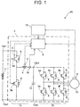
- FIG. 1 shows a block diagram showing an electric power system of an electric vehicle 90 including the electric power conversion system 2.
- the electric vehicle 90 of the embodiment includes a battery 11, the electric power conversion system 2, a high order controller 15, and a traveling motor 13.
- the electric vehicle 90 travels by driving the motor 13 with the electric power of the battery 11.
- the electric power conversion system 2 is connected between the battery 11 and the motor 13.
- the electric power conversion system 2 converts direct-current electric power output from the battery 11 into alternating-current electric power suitable for driving of the motor 13.
- the electric power conversion system 2 includes a voltage converter circuit 10, an inverter circuit 20, and an electric power controller 8.
- the voltage converter circuit 10 has high-voltage ends (a high-voltage end positive electrode 10a1, a high-voltage end negative electrode 10a2) connected to the battery 11.
- the voltage converter circuit 10 has low-voltage ends (a low-voltage end positive electrode 10b1, a low-voltage end negative electrode 10b2) connected to the inverter circuit 20.
- a set of the high-voltage end positive electrode 10a1 and the high-voltage end negative electrode 10a2 is referred to as a high-voltage end 10a
- a set of the low-voltage end positive electrode 10b1 and the low-voltage end negative electrode 10b2 is referred to as a low-voltage end 10b.
- the voltage converter circuit 10 has a step-down function for stepping down a voltage applied to the high-voltage end 10a and outputting the stepped-down voltage to the low-voltage end 10b, and a boosting function for boosting a voltage applied to the low-voltage end 10b and outputting the boosted voltage to the high-voltage end 10a. That is, the voltage converter circuit 10 is a bidirectional DC-DC converter.
- the voltage applied to the low-voltage end 10b is the voltage of electric power (regenerative electric power) obtained when the motor 13 is reversely driven with deceleration energy of the vehicle.
- the drive voltage of the motor 13 changes depending on a driver's accelerator work (accelerator operation amount) or the like, the maximum drive voltage is equal to the output voltage of the battery 11. That is, the motor 13 operates at a voltage equal to or less than the output voltage of the battery 11.
- the drive voltage of the motor 13 is determined by the accelerator operation amount or the like. For example, when the accelerator operation amount is large, the drive voltage of the motor 13 increases, whereas when the accelerator operation amount is small, the drive voltage also decreases.
- the electric power controller 8 operates the voltage converter circuit 10 to step down the output voltage of the battery 11 and supply the stepped-down voltage to the inverter circuit 20.
- the circuit configuration of the voltage converter circuit 10 will be described.
- Two switching elements 3a, 3b are connected in series between the high-voltage end positive electrode 10a1 and the high-voltage end negative electrode 10a2.
- the switching elements 3a, 3b are connected in reverse parallel to diodes 9, respectively.
- Connected between a middle point of a series connection of the two switching elements 3a, 3b and the low-voltage end positive electrode 10b1 is a reactor 5.
- the low-voltage end negative electrode 10b2 and the high-voltage end negative electrode 10a2 are directly connected.
- the voltage converter circuit 10 is of a chopper type including the switching elements 3a, 3b and the reactor 5.
- the switching elements 3a, 3b complementarily operate such that one element is turned on when the other element is turned off.
- the switching element 3a is involved in a step-down operation, while the switching element 3b is involved in a boosting operation.
- the voltage converter circuit 10 operates such that a voltage ratio between the high-voltage end 10a and the low-voltage end 10b becomes a target voltage ratio.
- the direction of a current flow is determined depending on the balance between the voltage on the side of the high-voltage end 10a and the voltage on the side of the low-voltage end 10b.
- the electric power controller 8 controls the switching elements 3a, 3b.
- dashed arrows represent signal lines.
- the voltage converter circuit 10 includes a temperature sensor 6 that measures the temperature of the switching element 3a, a temperature sensor 7 that measures the temperature of the reactor 5, and a current sensor 16 that measures the current flowing through the reactor 5. Measurement data by the temperature sensors 6, 7 and the current sensor 16 is sent to the electric power controller 8.
- the electric power controller 8 regulates the current flowing through the voltage converter circuit 10 to prevent the switching element 3a and the reactor 5 from overheating.
- the inverter circuit 20 will be described.
- the inverter circuit 20 includes six switching elements 4a-4f and six diodes 9.
- the diodes 9 are connected in reverse parallel to the switching elements 4a-4f, respectively.
- the six switching elements 4a-4f are paired to form series connections. Three series connections are connected in parallel. When the switching elements 4a-4f properly repeat on-off operation, an alternating current is output from middle points of the respective series connections.
- the electric power controller 8 also controls the six switching elements 4a-4f. In FIG. 1 , illustration of signal lines from the electric power controller 8 to the switching elements 4a-4f is omitted.
- a smoothing capacitor 12 is connected in parallel.
- the smoothing capacitor 12 is connected between the low-voltage end positive electrode 10b1 and the low-voltage end negative electrode 10b2 of the voltage converter circuit 10.
- the smoothing capacitor 12 suppresses pulsation of the current flowing between the voltage converter circuit 10 and the inverter circuit 20.
- the motor 13 is equipped with a rotational speed sensor 14 that measure the rotational speed of the motor 13.
- the measurement data of the rotational speed sensor 14 is also sent to the electric power controller 8.
- the electric power controller 8 controls the switching elements of the voltage converter circuit 10 and the inverter circuit 20 also in consideration of the rotational speed of the motor 13 measured with the rotational speed sensor 14.
- the electric power controller 8 is connected to the high order controller 15.
- the high order controller 15 determines a target output torque of the motor 13 based on information such as the accelerator operation amount.
- the target output torque is sent to the electric power controller 8.
- the drive voltage of the motor 13 is equal to or less than the output voltage of the battery 11.
- the electric power controller 8 determines a target voltage of the voltage converter circuit 10, and a target frequency of the output alternating current of the inverter circuit 20.
- the electric power controller 8 controls the switching elements 3a, 3b of the voltage converter circuit 10 and the switching elements 4a-4f of the inverter circuit 20 such that the determined target voltage and target frequency are achieved.
- the switching elements 3a, 3b and the reactor 5 generate a large amount of heat.
- the electric power controller 8 controls the switching elements 3a, 3b so as to prevent the switching elements 3a, 3b (switching element 3a that involves in voltage step-down in particular) and the reactor 5 from overheating.
- the electric power controller 8 controls the voltage converter circuit 10 such that the voltage of the low-voltage end 10b becomes equal to the voltage of the high-voltage end 10a. Specifically, the electric power controller 8 keeps the switching element 3a in an ON state, while keeping the switching element 3b in an OFF state. As a consequence, the high-voltage end positive electrode 10a1 and the low-voltage end positive electrode 10b1 are in a connected state at all the time, so that the voltages on both the ends become equal.
- a preferable drive voltage of the motor 13 changes with the accelerator operation amount or the like.
- priority is given to preventing the switching element 3a or the reactor 5 from overheating.
- the switching element 3a is kept in the ON state, while the switching element 3b is kept in the OFF state.
- pulsation of the current relating to on-off of the switching elements 3a, 3b is eliminated, and heat generation in the switching element 3a and the reactor 5 is suppressed.
- the electric power controller 8 constantly monitors the temperature of the switching element 3a and the temperature of the reactor 5 with the temperature sensors 6, 7. When the temperature of the switching element 3a or the reactor 5 exceeds a temperature threshold, the electric power controller 8 keeps the switching element 3a in the ON state, while keeping the switching element 3b in the OFF state irrespective of the magnitude of the electric power consumed in the motor 13. That is, the electric power controller 8 controls the switching elements 3a, 3b such that the voltage of the high-voltage end 10a and the voltage of the low-voltage end 10b become equal. This makes it possible to prevent further increase in temperature of the switching element 3a and the reactor 5.
- FIG. 2 shows a flowchart of an output voltage determination process executed by the electric power controller 8. The process of the electric power controller 8 will be described with reference to FIG. 2 . The process of FIG. 2 is periodically executed.
- the electric power controller 8 acquires data from the temperature sensors 6, 7, and compares the data with the temperature threshold. Specifically, the electric power controller 8 compares the temperature measured by the temperature sensor 7 (i.e., the temperature of the reactor 5) with a first temperature threshold Tth1 (step S2). When the temperature of the reactor 5 exceeds the first temperature threshold Tth1 (step S2: NO), the electric power controller 8 shifts to the process of step S8. In step S8, the electric power controller 8 sets, as an output voltage, a value same as an input voltage. The electric power controller 8 then controls the switching elements 3a, 3b (step S7). As described before, when step S8 is executed, the electric power controller 8 keeps the switching element 3a in the ON state, and keeps the switching element 3b in the OFF state in step S7.
- step S2 When the temperature of the reactor is equal to or less than the first temperature threshold Tth1 (step S2: YES), the electric power controller 8 compares the temperature measured by the temperature sensor 6 (that is, the temperature of the switching element 3a) with a second temperature threshold Tth2 (step S3). When the temperature of the switching element 3a exceeds the second temperature threshold Tth2, the electric power controller 8 sets, as an output voltage, a value same as an input voltage as in the case of step S2 (step S3: NO, S8).
- step S3 YES
- the electric power controller 8 identifies the electric power consumed in the motor 13 based on the TN diagram (step S4).
- step S5: NO, S8 the electric power controller 8 sets, as output electric power, a value same as an input electric power.
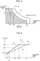
- FIG. 3 is a TN diagram having a horizontal axis indicating the rotational speed of the motor 13 and a vertical axis indicating the output torque of the motor 13.
- a position in the graph of FIG. 3 is identified.
- equal electric power lines can be depicted.
- a range A in FIG. 3 (gray range) represents the range where the output electric power Pw of the motor 13 relative to the target output torque is smaller than the electric power threshold Pth.
- a range B represents the range where the output electric power Pw of the motor 13 relative to the target output torque is larger than the electric power threshold Pth.
- the output electric power Pw of the motor 13 is equivalent to the electric power consumed in the motor 13.
- the electric power controller 8 refers to the TN diagram to check whether or not the output electric power Pw of the motor 13 exceeds the electric power threshold Pth based on the target output and the current rotational speed of the motor 13.
- the electric power controller 8 sets, as an output voltage of the voltage converter circuit 10, a value same as the input voltage (step S5: NO, S8). In this case, as described before, the electric power controller 8 keeps the switching element 3a in the ON state while keeping the switching element 3b in the OFF state in the process of step S7.
- step S5 When the electric power Pw consumed in the motor 13 does not exceed the electric power threshold Pth (step S5: YES), the electric power controller 8 determines the output voltage of the voltage converter circuit 10 based on the rotational speed of the motor 13 (step S6).
- the electric power controller 8 stores a map (output voltage map) that defines a relationship between the rotational speed of the motor 13 with the output torque being constant and the output voltage of the voltage converter circuit 10.
- FIG. 4 shows one example of the output voltage map.
- the horizontal axis of FIG. 4 represents the rotational speed of the motor 13, and the vertical axis represents the output voltage of the voltage converter circuit 10.
- a point Q can be identified on the TN diagram of FIG. 3 .
- a broken line DL in FIG. 3 is a line extending through the point Q with the output torque being constant at Ta.
- a map that defines a relationship between the rotational speed and the output voltage on this line is the map of FIG. 4 .
- the map same as FIG. 4 is prepared for every output torque for the electric power controller 8.
- a graph G1 of a thick line determines the output voltage of the voltage converter circuit 10 relative to the rotational speed of the motor 13.
- a graph Ga of a dotted line represents a voltage required for maximum efficiency phase control of the motor 13. The voltage required for maximum efficiency phase control is proportional to the rotational speed of the motor 13 as shown by the graph Ga.
- the output voltage of the voltage converter circuit 10 is determined in accordance with the rotational speed of the motor 13 on the graph Ga (voltage required for maximum efficiency phase control). For example, when the rotational speed of the motor 13 is Wa, the output voltage of the voltage converter circuit 10 is determined to be a voltage Va from the graph G1.
- a voltage Vmin is a minimum voltage that can stably be output by the voltage converter circuit 10. Therefore, when the rotational speed is lower than W1, the output voltage of the voltage converter circuit 10 is set to the voltage Vmin. In the range where the electric power consumed in the motor 13 is smaller than the electric power threshold Pth, the output voltage of the voltage converter circuit 10 becomes a value lower than the input voltage.
- a range where the rotational speed is larger than W2 belongs to the range B of FIG. 3 .
- the output voltage of the voltage converter circuit 10 is determined to be an input voltage Vin regardless of the electric power consumed in the motor 13.
- the input voltage Vin is equal to the output voltage of the battery 11.
- the output voltage of the voltage converter circuit 10 is determined based on the voltage required for maximum efficiency phase control of the motor 13.
- the output voltage of the voltage converter circuit 10 may be determined based on the voltage required for field-weakening control instead of the maximum efficiency phase control.
- the voltage required for field-weakening control is also proportional to the rotational speed of the motor 13.
- a graph Gb of FIG. 4 represents the voltage of the motor 13 required for field-weakening control.
- the output voltage may be determined to be proportional to the rotational speed of the motor 13 along with the graph Gb. However, the minimum value of the output voltage is still the voltage Vmin, and the maximum value is the voltage Vin.
- step S6 the electric power controller 8 controls the switching elements 3a, 3b of the voltage converter circuit 10 such that the determined output voltage is achieved.
- the voltage converter circuit 10 keeps the switching element 3a in the ON state while keeping the switching element 3b in the OFF state such that the output electric power may become equal to the input electric power. As a result, a pulsating current is prevented from flowing to the switching element 3a and the reactor 5, and thereby generation of heat is suppressed.
- the electric power controller 8 controls the switching elements 3a, 3b such that the output voltage of the voltage converter circuit 10 becomes lower than the input voltage.
- the electric power conversion system 2 of the embodiment can suppress generation of heat by keeping the switching element 3a in the ON state, when large electric power is supplied to the motor 13.
- FIG. 5 shows a graph when the horizontal axis indicates a current flowing to the reactor 5 and the vertical axis indicates reactance of the reactor 5.
- the reactance of the reactor rapidly lowers at a prescribed current value.
- the current value at which the reactance rapidly lowers is a magnetic saturation current Ith.
- a current Imax of FIG. 5 is a maximum current that flows to the motor 13.
- the magnetic saturation current Ith of the reactor 5 used for the electric power conversion system 2 of the embodiment may be smaller than the current Imax flowing to the motor 13. This is because the reactor 5 does not need to function when a large electric power flows into the motor 13.
- the voltage converter circuit 10 keeps the switching element 3a in the ON state, when the electric power consumed in the motor 13 exceeds the electric power threshold Pth.
- the current flowing into the voltage converter circuit 10 is Pth / Vin.
- the voltage Vin is an input voltage of the voltage converter circuit 10, which is equal to an output voltage VB of the battery 11.
- the upper limit of the current that flows into the reactor 5 when the step-down operation is required is Pth / VB.
- the magnetic saturation current Ith may be equal to the current value (Pth / VB). In other words, the magnetic saturation current of the reactor 5 may be smaller than the maximum value of the current that flows into the inverter circuit 20.
- FIG. 6 shows a block diagram of an electric vehicle 91 including an electric power conversion system 2a of a second embodiment.
- the electric power conversion system 2a includes a voltage converter circuit 110, an inverter circuit 20, and an electric power controller 8.
- the voltage converter circuit 110 has a high-voltage end 110a connected to the battery 11, and a low-voltage end 110b connected to the inverter circuit 20.
- the electric power conversion system 2a is different from the electric power conversion system 2 of the first embodiment in that the electric power conversion system 2a includes an overcurrent protection device 106 and a charging port 107.
- Other configuration aspects are the same as the electric power conversion system 2 of the first embodiment. Therefore, description of the configuration other than the overcurrent protection device 106 and the charging port 107 is omitted.
- the overcurrent protection device 106 is a fuse that is fused when a current of a prescribed magnitude or more flows.
- the voltage converter circuit 110 is a bidirectional DC-DC converter like the voltage converter circuit 10 of the first embodiment.
- the switching element 3b is involved in the boosting operation.
- the switching element 3b is connected between the positive electrode line 19a and the negative electrode line 19b. Accordingly, when the switching element 3b has a short fault, the positive electrode line 19a and the negative electrode line 19b are short-circuited, and a large current flows.
- the overcurrent protection device 106 is immediately fused, which disconnects between the positive electrode line 19a and the negative electrode lines 19b.
- the voltage converter circuit 110 is unable to perform the step-down operation.
- the electric power controller 8 keeps the switching element 3a in the ON state.
- the switching element 3a is kept in the ON state, a high-voltage end positive electrode 110a1 and a low-voltage end positive electrode 110b1 are directly coupled, and the electric power of the battery 11 directly flows into the inverter circuit 20. Therefore, the electric vehicle 91 can keep on traveling.
- the charging port 107 is connected between the low-voltage end positive electrode 110b1 and the low-voltage end negative electrode 110b2 of the voltage converter circuit 110.
- the charging port 107 may be connected to an external power source.
- the voltage converter circuit 110 is a bidirectional DC-DC converter, the voltage converter circuit 110 can boost the voltage input into the low-voltage end 110b, and output the boosted voltage from the high-voltage end 110a. Therefore, it is possible to connect an external power source, that is lower in voltage than the battery 11, to the charging port 107 and charge the battery 11.
- An electric power conversion system of a modification does not include a switching element 3b.
- Such a voltage converter circuit 110 can perform step-down operation though it does not support boosting operation.
- a diode 9a and an overcurrent protection device 106 are connected in series between a positive electrode line 19a and a negative electrode line 19b. Even when the diode 9a has a short fault, and a large current flows between the positive electrode line 19a and the negative electrode line 19b, the overcurrent protection device 106 is fused, which disconnects between the positive electrode line 19a and the negative electrode lines 19b.
- the electric power controller 8 can keep the switching element 3a in the ON state, and the electric vehicle 91 can keep on traveling.
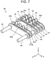
- FIG. 7 is a perspective view of a stacking unit 40
- FIG. 8 is a plan view of the stacking unit 40 connected to a bus bar.
- a capacitor element 50 is depicted in addition to the stacking unit 40.
- the capacitor element 50 is equivalent to the smoothing capacitor 12 of FIG. 1 .
- the stacking unit 40 is a device including an integration of the switching elements 3a, 3b included in the voltage converter circuit 10, the switching elements 4a-4f included in the inverter circuit 20, and a reactor 35.
- the reactor 35 is equivalent to the reactor 5 of FIG. 1 .
- the stacking unit 40 is constituted of a first semiconductor module 30a, second semiconductor modules 30b, 30c, 30d, a plurality of coolers 41, and the reactor 35.
- the first semiconductor module 30a houses the switching elements 3a, 3b of the voltage converter circuit 10, and the diodes 9 connected in reverse parallel to the switching elements, respectively.
- the switching elements 3a, 3b are connected in series in the first semiconductor module 30a.
- the second semiconductor module 30b houses switching elements 4a, 4b of the inverter circuit 20, and the diodes 9 connected in reverse parallel to the switching elements, respectively.
- the switching elements 4a, 4b are connected in series inside the second semiconductor module 30b.
- the second semiconductor modules 30c, 30d have the same structure as the second semiconductor module 30b.
- the second semiconductor modules 30c, 30d each house two switching elements and two diodes.
- the second semiconductor modules 30b-30d have the same structure as the first semiconductor module 30a.
- the first semiconductor module 30a and the second semiconductor modules 30b-30d are collectively referred to as the semiconductor modules 30. From one narrow-width surface of each of the semiconductor modules 30, a positive electrode terminal 31, a negative electrode terminal 32, and a middle point terminal 33 extend.
- each of the positive electrode terminals 31 is connected with a positive electrode side of each series connection of two switching elements, while each of the negative electrode terminals 32 is connected to a negative electrode side of each of the series connections.
- each of the middle point terminals 33 is connected with a middle point of each series connections of two switching elements.
- the coolers 41 are linear tubes that carry a coolant.
- the coolers 41 are arranged in parallel, with the semiconductor modules 30 or the reactor 35 being interposed between the adjacent coolers 41.
- the adjacent coolers 41 are connected through two connecting tubules 42a, 42b.
- Each of the linear coolers 41 has one longitudinal end that is connected to the connecting tubule 42a, and the other longitudinal end that is connected to the connecting tubule 42b.
- the cooler 41a at the end of a lining of the coolers 41 is connected to a supply pipe 43 and a discharge pipe 44.
- the supply pipe 43 is arranged to be overlapped with the connecting tubule 42a
- the discharge pipe 44 is arranged to be overlapped with the connecting tubule 42b.
- the supply pipe 43 and the discharge pipe 44 are connected to an unshown coolant circulation device.
- the coolant is supplied through the supply pipe 43 from the coolant circulation device.
- the coolant is distributed to all the coolers 41 through the connecting tubule 42a.
- the coolant absorbs the heat of the adjacent semiconductor modules 30 or the reactor 35, while flowing through the inside of the coolers 41.
- the coolant that absorbed heat is returned to the coolant circulation device through the connecting tubule 42b and the discharge pipe 44.
- Both sides of the semiconductor modules 30 and the reactor 35 are in contact with the coolers 41 such that the semiconductor modules 30 and the reactor 35 are cooled from both the sides thereof.
- the stacking unit 40 collectively cools the switching elements and the reactor 35.
- FIG. 8 shows a plan view of the stacking unit 40.
- FIG. 8 also depicts bus bars 51-56 connected with each terminal of the semiconductor modules 30 and the capacitor element 50.
- the bus bars are conductive members formed from metal with a small internal resistance.
- the first bus bar 51 has one end connected to the positive electrode terminal 31 of the first semiconductor module 30a.
- the first bus bar 51 has the other end serving as a connection terminal 51a that is connected to a positive electrode line of a power cable extending from the battery 11.
- the other end (connection terminal 51a) of the first bus bar 51 corresponds to the high-voltage end positive electrode 10a1 of the voltage converter circuit 10.
- the second bus bar 52 has one end connected to the negative electrode terminal 32 of the first semiconductor module 30a, and the other end connected to an electrode 50b of the capacitor element 50.
- the second bus bar 52 is also connected to the negative electrode terminals 32 of the second semiconductor modules 30b-30 in some midpoint.
- the second bus bar 52 is also connected to one end of the third bus bar 53 at a portion of the electrode 50b.
- the third bus bar 53 has the other end serving as a connection terminal 53a that is connected to a negative electrode line of the power cable extending from the battery 11.
- the other end (connection terminal 53a) of the third bus bar 53 corresponds to the high-voltage end negative electrode 10a2 of the voltage converter circuit 10.
- the second bus bar 52 and the third bus bar 53 are equivalent to the negative electrode lines of the voltage converter circuit 10 and the inverter circuit 20.
- the fourth bus bar 54 connects between the middle point terminal 33 of the first semiconductor module 30a and the first terminal 36 of the reactor 35.
- the fifth bus bar 55 connects a second terminal 37 of the reactor 35, an electrode 50a of the capacitor element 50, and the positive electrode terminals 31 of the second semiconductor modules 30b-30d.
- the three sixth bus bars 56 connect with the middle point terminals 33 of the second semiconductor modules 30b-30d, respectively.
- the three sixth bus bars 56 have the other ends serving as connection terminals 56a.
- the other ends (connection terminals 56a) of the three sixth bus bars 56 are equivalent to three-phase alternating current output ends of the inverter circuit 20.
- the semiconductor modules 30 and the reactor 35 are connected in a compact and organized manner through the bus bars 51-56.
- the reactor 35 is arranged between the first semiconductor module 30a and the second semiconductor modules 30b-30d. Such arrangement achieves compact cabling of the bus bars 51-56 that connect the semiconductor modules 30 and the reactor 35.
- the electric power controller 8 adjusts the output voltage to be equal to the input voltage, when the electric power consumed in the motor 13 is larger than the electric power threshold Pth.
- the electric power controller 8 may change the output voltage by monitoring the current flowing into the inverter circuit 20 instead of the electric power consumed in the motor 13.
- the current that is, the current measured by the current sensor 16
- the current flowing through the reactor 5 of the voltage converter circuit 10 is supplied to the inverter circuit 20. Therefore, the current flowing into the inverter circuit 20 is measurable by the current sensor 16 of the voltage converter circuit 10.
- the electric power controller 8 may be configured to adjust the output voltage to be equal to the input voltage.
- the battery 11 is equivalent to one example of the direct-current power source.
- the direct-current power source may be a fuel cell.
- the voltage converter circuit may be a voltage step-down converter that can support only the step-down operation.
Landscapes
- Engineering & Computer Science (AREA)
- Power Engineering (AREA)
- Transportation (AREA)
- Mechanical Engineering (AREA)
- Life Sciences & Earth Sciences (AREA)
- Sustainable Development (AREA)
- Sustainable Energy (AREA)
- Inverter Devices (AREA)
- Dc-Dc Converters (AREA)
- Electric Propulsion And Braking For Vehicles (AREA)
Abstract
Description
- The present specification discloses a technique related to an electric power conversion system that converts electric power of a direct-current power source to drive electric power of a traveling motor, and a control method of an electric power conversion system.
- Electric power conversion systems that convert electric power of a direct-current power source into drive electric power of a traveling motor are disclosed in
WO 2003/015254 and Japanese Patent Application Publication No.2017-093055 JP 2017-093055 A WO 2003/015254 includes a boost converter that boosts electric power of the direct-current power source, and an inverter that converts the boosted direct-current electric power into alternating-current electric power. The electric power conversion system ofJP 2017-093055 A WO 2003/015254 and the first and second voltage converters ofJP 2017-093055 A - Since a large current flows in an electric power conversion system for an electric vehicle, the amount of heat generation in the electric power conversion system is large. When the current or electric power supplied to a traveling motor is large in particular, the current flowing into the electric power conversion system also becomes large. Hence, the amount of heat generation increases. A chopper voltage converter generates a pulsating current with on-off of a switching element, and the switching element itself and a reactor generate heat. The present invention relates to an electric power conversion system that converts electric power of a direct-current power source into drive electric power of a traveling motor, the electric power conversion system suppressing the amount of heat generation when the current or electric power supplied to the traveling motor is large.
- A first aspect of the present invention is an electric power conversion system that converts electric power of a direct-current power source into drive electric power of a traveling motor. The electric power conversion system includes: an inverter; a voltage converter; and a controller. The inverter is configured to supply alternating-current electric power to the traveling motor. The voltage converter includes a high-voltage end connected to the direct-current power source and a low-voltage end connected to the inverter. The voltage converter includes switching elements and a reactor, and is configured to step down the voltage of the direct-current power source and supply the voltage of the direct-current power source to the inverter. The controller is configured to control the voltage converter. The controller is configured to control the switching elements such that the voltage of the low-voltage end becomes lower than the voltage of the high-voltage end in a first state. The first state is at least one state out of a state where a current flowing to the inverter is less than a prescribed current threshold and a state where electric power consumed in the traveling motor is less than a prescribed electric power threshold. The controller is configured to control the switching elements such that the voltage of the low-voltage end becomes equal to the voltage of the high-voltage end in a second state. The second state is at least one state out of a state where the current flowing to the inverter is more than the prescribed current threshold and a state where the electric power consumed in the traveling motor is more than the prescribed electric power threshold. The phrase "less than the threshold" may be "equal to or less than the threshold". The phrase "more than the threshold" may be "equal to or more than the threshold".
- With the configuration, the controller of the electric power conversion system controls the voltage converter such that the voltage at the low-voltage end becomes equal to the voltage at the high-voltage end, when a current flowing to the inverter or electric power consumed in the traveling motor is larger than a threshold. In the case of a chopper voltage converter, the voltage at the high-voltage end may be adjusted to be equal to the voltage at the low-voltage end by keeping a switching element that is involved in voltage step-down in an ON state (in the case of a bidirectional DC-DC converter, a switching element involved in voltage step-down is kept in the ON state, while a switching element involved in boosting is kept in an OFF state). This makes it possible to prevent generation of a pulsating current and to suppress generation of heat in the switching elements and the reactor.
- In the electric power conversion system, the prescribed current threshold and the prescribed electric power threshold may be determined based on a rotational speed and an output torque of the traveling motor. Generally, the characteristics of a motor are expressed by a graph called a TN diagram. The TN diagram is a graph when a horizontal axis indicates the rotational speed of the motor and a vertical axis indicates the output torque of the motor. On the TN diagram, a curve of a constant output electric power of the motor can be plotted. When the above-described threshold is expressed with a unit of electric power, the threshold can be expressed as a curve on the TN diagram. With the configuration, the threshold is determined based on the rotational speed and the output torque of the traveling motor, the threshold of electric power can be calculated from a target rotational speed and a target torque.
- In the electric power conversion system, the voltage converter may be a bidirectional DC-DC converter including a voltage step-down function for stepping down the voltage of the high-voltage end and outputting the voltage of the high-voltage end from the low-voltage end, and a boosting function for boosting the voltage of the low-voltage end and outputting the voltage of the low-voltage end from the high-voltage end. The low-voltage end of the voltage converter may be connected to a charging port. With the configuration, when the direct-current power source is a rechargeable secondary battery, the voltage of an external power source is boosted with the voltage converter included in the electric power conversion system and is used to charge the secondary battery. This eliminates the necessity of a voltage regulator for the external power source.
- In the electric power conversion system, the controller may be configured to control the switching elements such that the voltage of the low-voltage end becomes equal to the voltage of the high-voltage end in a fifth state irrespective of the magnitude of the current flowing to the inverter or the electric power consumed in the traveling motor. The fifth state may be at least one state out of a state where the temperature of the switching elements exceeds a first prescribed temperature threshold, and a state where the temperature of the reactor exceeds a second prescribed temperature threshold. The terms "first prescribed temperature threshold and second prescribed temperature threshold" refer to protection temperatures in order to prevent failure of the switching elements and the reactor. With the configuration, the switching elements or the reactor can be prevented from overheating irrespective of the magnitude of the current flowing to the inverter or the electric power consumed in the traveling motor.
- In the electric power conversion system, the voltage converter may include a semiconductor element connected between the positive electrode line and the negative electrode line, and an overcurrent protection device connected in series to the semiconductor element. With the configuration, even when the semiconductor element is short-circuited, the overcurrent protection device separates the semiconductor element, so that the short-circuit can be cancelled. When the overcurrent protection device operates, the step-down operation by the voltage converter becomes inoperable. However, the voltage same as an input voltage can still be output. That is, even after the overcurrent protection device operates, it is possible to keep on driving the traveling motor.
- In the electric power conversion system, a magnetic saturation current of the reactor may be smaller than a maximum input current of the inverter. In other words, since the reactor is not used when the current is large, a large-sized reactor that functions when the input current of the inverter is maximum is unnecessary.
- In the electric power conversion system, the voltage converter may include a first semiconductor module that houses the switching elements. The inverter may include second semiconductor modules that house power conversion switching elements. The reactor may be provided between the first semiconductor module and the second semiconductor modules. With the configuration, a bus bar that connects the first semiconductor module and the second semiconductor module to the reactor is easily cabled.
- A second aspect of the present invention is a control method of an electric power conversion system. The electric power conversion system includes: an inverter; a voltage converter; and a controller. The inverter is configured to supply alternating-current electric power to the traveling motor. The voltage converter has a high-voltage end connected to the direct-current power source and a low-voltage end connected to the inverter. The voltage converter includes switching elements and a reactor, and is configured to step down a voltage of the direct-current power source and supply the voltage of the direct-current power source to the inverter. The controller is configured to control the voltage converter. The control method includes: controlling, by the controller, the switching elements such that a voltage of the low-voltage end becomes lower than a voltage of the high-voltage end in a first state, the first state being at least one state out of a state where a current flowing to the inverter is less than a prescribed current threshold and a state where electric power consumed in the traveling motor is less than a prescribed electric power threshold; and controlling, by the controller, the switching elements such that the voltage of the low-voltage end becomes equal to the voltage of the high-voltage end in a second state, the second state being at least one state out of a state where the current flowing to the inverter is more than the prescribed current threshold and a state where the electric power consumed in the traveling motor is more than the prescribed electric power threshold.
- Features, advantages, and technical and industrial significance of exemplary embodiments of the invention will be described below with reference to the accompanying drawings, in which like numerals denote like elements, and wherein:
-
FIG. 1 is a block diagram showing an electric power system of an electric vehicle including an electric power conversion system of a first embodiment; -
FIG. 2 is a flowchart of a process of determining an output voltage of a voltage converter; -
FIG. 3 is one example of a TN diagram of a motor; -
FIG. 4 is one example of an output voltage map of the voltage converter; -
FIG. 5 is a graph showing one example of the characteristics of a reactor; -
FIG. 6 is a block diagram showing an electric power system of an electric vehicle including an electric power conversion system of a second embodiment; -
FIG. 7 is a perspective view of a stacking unit including an integration of switching elements and a reactor; and -
FIG. 8 is a plan view of the stacking unit. - With reference to
FIGS. 1 to 5 , an electricpower conversion system 2 of a first embodiment will be described.FIG. 1 shows a block diagram showing an electric power system of anelectric vehicle 90 including the electricpower conversion system 2. Theelectric vehicle 90 of the embodiment includes abattery 11, the electricpower conversion system 2, ahigh order controller 15, and a travelingmotor 13. Theelectric vehicle 90 travels by driving themotor 13 with the electric power of thebattery 11. The electricpower conversion system 2 is connected between thebattery 11 and themotor 13. The electricpower conversion system 2 converts direct-current electric power output from thebattery 11 into alternating-current electric power suitable for driving of themotor 13. - The electric
power conversion system 2 includes avoltage converter circuit 10, aninverter circuit 20, and anelectric power controller 8. - First, the
voltage converter circuit 10 will be described. Thevoltage converter circuit 10 has high-voltage ends (a high-voltage end positive electrode 10a1, a high-voltage end negative electrode 10a2) connected to thebattery 11. Thevoltage converter circuit 10 has low-voltage ends (a low-voltage end positive electrode 10b1, a low-voltage end negative electrode 10b2) connected to theinverter circuit 20. For the convenience of description, a set of the high-voltage end positive electrode 10a1 and the high-voltage end negative electrode 10a2 is referred to as a high-voltage end 10a, and a set of the low-voltage end positive electrode 10b1 and the low-voltage end negative electrode 10b2 is referred to as a low-voltage end 10b. - The
voltage converter circuit 10 has a step-down function for stepping down a voltage applied to the high-voltage end 10a and outputting the stepped-down voltage to the low-voltage end 10b, and a boosting function for boosting a voltage applied to the low-voltage end 10b and outputting the boosted voltage to the high-voltage end 10a. That is, thevoltage converter circuit 10 is a bidirectional DC-DC converter. The voltage applied to the low-voltage end 10b is the voltage of electric power (regenerative electric power) obtained when themotor 13 is reversely driven with deceleration energy of the vehicle. - Although the drive voltage of the
motor 13 changes depending on a driver's accelerator work (accelerator operation amount) or the like, the maximum drive voltage is equal to the output voltage of thebattery 11. That is, themotor 13 operates at a voltage equal to or less than the output voltage of thebattery 11. The drive voltage of themotor 13 is determined by the accelerator operation amount or the like. For example, when the accelerator operation amount is large, the drive voltage of themotor 13 increases, whereas when the accelerator operation amount is small, the drive voltage also decreases. When a proper drive voltage of themotor 13 is lower than the output voltage of thebattery 11, theelectric power controller 8 operates thevoltage converter circuit 10 to step down the output voltage of thebattery 11 and supply the stepped-down voltage to theinverter circuit 20. - The circuit configuration of the
voltage converter circuit 10 will be described. Two switchingelements switching elements diodes 9, respectively. Connected between a middle point of a series connection of the twoswitching elements reactor 5. The low-voltage end negative electrode 10b2 and the high-voltage end negative electrode 10a2 are directly connected. As shown inFIG. 1 , thevoltage converter circuit 10 is of a chopper type including theswitching elements reactor 5. - The
switching elements element 3a is involved in a step-down operation, while theswitching element 3b is involved in a boosting operation. Thevoltage converter circuit 10 operates such that a voltage ratio between the high-voltage end 10a and the low-voltage end 10b becomes a target voltage ratio. The direction of a current flow is determined depending on the balance between the voltage on the side of the high-voltage end 10a and the voltage on the side of the low-voltage end 10b. - The
electric power controller 8 controls theswitching elements FIG. 1 , dashed arrows represent signal lines. Thevoltage converter circuit 10 includes atemperature sensor 6 that measures the temperature of theswitching element 3a, atemperature sensor 7 that measures the temperature of thereactor 5, and acurrent sensor 16 that measures the current flowing through thereactor 5. Measurement data by thetemperature sensors current sensor 16 is sent to theelectric power controller 8. Theelectric power controller 8 regulates the current flowing through thevoltage converter circuit 10 to prevent theswitching element 3a and thereactor 5 from overheating. - The
inverter circuit 20 will be described. Theinverter circuit 20 includes sixswitching elements 4a-4f and sixdiodes 9. Thediodes 9 are connected in reverse parallel to theswitching elements 4a-4f, respectively. The sixswitching elements 4a-4f are paired to form series connections. Three series connections are connected in parallel. When theswitching elements 4a-4f properly repeat on-off operation, an alternating current is output from middle points of the respective series connections. Theelectric power controller 8 also controls the sixswitching elements 4a-4f. InFIG. 1 , illustration of signal lines from theelectric power controller 8 to theswitching elements 4a-4f is omitted. - Between the
voltage converter circuit 10 and theinverter circuit 20, a smoothingcapacitor 12 is connected in parallel. In other words, the smoothingcapacitor 12 is connected between the low-voltage end positive electrode 10b1 and the low-voltage end negative electrode 10b2 of thevoltage converter circuit 10. The smoothingcapacitor 12 suppresses pulsation of the current flowing between thevoltage converter circuit 10 and theinverter circuit 20. - The
motor 13 is equipped with arotational speed sensor 14 that measure the rotational speed of themotor 13. The measurement data of therotational speed sensor 14 is also sent to theelectric power controller 8. Theelectric power controller 8 controls the switching elements of thevoltage converter circuit 10 and theinverter circuit 20 also in consideration of the rotational speed of themotor 13 measured with therotational speed sensor 14. - The
electric power controller 8 is connected to thehigh order controller 15. Thehigh order controller 15 determines a target output torque of themotor 13 based on information such as the accelerator operation amount. The target output torque is sent to theelectric power controller 8. - As stated before, the drive voltage of the
motor 13 is equal to or less than the output voltage of thebattery 11. Upon reception of the target output torque, theelectric power controller 8 determines a target voltage of thevoltage converter circuit 10, and a target frequency of the output alternating current of theinverter circuit 20. Theelectric power controller 8 controls theswitching elements voltage converter circuit 10 and theswitching elements 4a-4f of theinverter circuit 20 such that the determined target voltage and target frequency are achieved. Theswitching elements reactor 5 generate a large amount of heat. Theelectric power controller 8 controls theswitching elements switching elements element 3a that involves in voltage step-down in particular) and thereactor 5 from overheating. When the electric power consumed in themotor 13 exceeds a prescribed threshold (electric power threshold Pth), theelectric power controller 8 controls thevoltage converter circuit 10 such that the voltage of the low-voltage end 10b becomes equal to the voltage of the high-voltage end 10a. Specifically, theelectric power controller 8 keeps the switchingelement 3a in an ON state, while keeping theswitching element 3b in an OFF state. As a consequence, the high-voltage end positive electrode 10a1 and the low-voltage end positive electrode 10b1 are in a connected state at all the time, so that the voltages on both the ends become equal. - A preferable drive voltage of the
motor 13 changes with the accelerator operation amount or the like. In the electricpower conversion system 2 of the embodiment, priority is given to preventing theswitching element 3a or thereactor 5 from overheating. When large electric power is expected to flow into the switchingelement 3a or thereactor 5, the switchingelement 3a is kept in the ON state, while theswitching element 3b is kept in the OFF state. Hence, pulsation of the current relating to on-off of theswitching elements switching element 3a and thereactor 5 is suppressed. - The
electric power controller 8 constantly monitors the temperature of theswitching element 3a and the temperature of thereactor 5 with thetemperature sensors switching element 3a or thereactor 5 exceeds a temperature threshold, theelectric power controller 8 keeps the switchingelement 3a in the ON state, while keeping theswitching element 3b in the OFF state irrespective of the magnitude of the electric power consumed in themotor 13. That is, theelectric power controller 8 controls theswitching elements switching element 3a and thereactor 5. -
FIG. 2 shows a flowchart of an output voltage determination process executed by theelectric power controller 8. The process of theelectric power controller 8 will be described with reference toFIG. 2 . The process ofFIG. 2 is periodically executed. - The
electric power controller 8 acquires data from thetemperature sensors electric power controller 8 compares the temperature measured by the temperature sensor 7 (i.e., the temperature of the reactor 5) with a first temperature threshold Tth1 (step S2). When the temperature of thereactor 5 exceeds the first temperature threshold Tth1 (step S2: NO), theelectric power controller 8 shifts to the process of step S8. In step S8, theelectric power controller 8 sets, as an output voltage, a value same as an input voltage. Theelectric power controller 8 then controls theswitching elements electric power controller 8 keeps the switchingelement 3a in the ON state, and keeps the switchingelement 3b in the OFF state in step S7. - When the temperature of the reactor is equal to or less than the first temperature threshold Tth1 (step S2: YES), the
electric power controller 8 compares the temperature measured by the temperature sensor 6 (that is, the temperature of theswitching element 3a) with a second temperature threshold Tth2 (step S3). When the temperature of theswitching element 3a exceeds the second temperature threshold Tth2, theelectric power controller 8 sets, as an output voltage, a value same as an input voltage as in the case of step S2 (step S3: NO, S8). - When the temperature of the
switching element 3a is equal to or less than the second temperature threshold Tth2 (step S3: YES), theelectric power controller 8 identifies the electric power consumed in themotor 13 based on the TN diagram (step S4). When the electric power consumed in themotor 13 exceeds the prescribed electric power threshold Pth (step S5: NO, S8), theelectric power controller 8 sets, as output electric power, a value same as an input electric power. - The process of step S4, S5 will be described.
FIG. 3 is a TN diagram having a horizontal axis indicating the rotational speed of themotor 13 and a vertical axis indicating the output torque of themotor 13. When a current rotational speed of themotor 13 and a target output torque of themotor 13 are determined, a position in the graph ofFIG. 3 is identified. In the TN diagram, equal electric power lines can be depicted. In the TN diagram ofFIG. 3 , a curve of the electric power Pw = electric power threshold Pth is depicted. A range A inFIG. 3 (gray range) represents the range where the output electric power Pw of themotor 13 relative to the target output torque is smaller than the electric power threshold Pth. A range B represents the range where the output electric power Pw of themotor 13 relative to the target output torque is larger than the electric power threshold Pth. The output electric power Pw of themotor 13 is equivalent to the electric power consumed in themotor 13. Theelectric power controller 8 refers to the TN diagram to check whether or not the output electric power Pw of themotor 13 exceeds the electric power threshold Pth based on the target output and the current rotational speed of themotor 13. When the output electric power Pw of the motor 13 (that is, the electric power consumed in the motor 13) exceeds the electric power threshold Pth, theelectric power controller 8 sets, as an output voltage of thevoltage converter circuit 10, a value same as the input voltage (step S5: NO, S8). In this case, as described before, theelectric power controller 8 keeps the switchingelement 3a in the ON state while keeping theswitching element 3b in the OFF state in the process of step S7. - When the electric power Pw consumed in the
motor 13 does not exceed the electric power threshold Pth (step S5: YES), theelectric power controller 8 determines the output voltage of thevoltage converter circuit 10 based on the rotational speed of the motor 13 (step S6). - The process of determining the output voltage will be described with reference to
FIGS. 3 and 4 . Theelectric power controller 8 stores a map (output voltage map) that defines a relationship between the rotational speed of themotor 13 with the output torque being constant and the output voltage of thevoltage converter circuit 10.FIG. 4 shows one example of the output voltage map. The horizontal axis ofFIG. 4 represents the rotational speed of themotor 13, and the vertical axis represents the output voltage of thevoltage converter circuit 10. For example, when the rotational speed at a current time is Wa, and the target output torque of themotor 13 is Ta, a point Q can be identified on the TN diagram ofFIG. 3 . A broken line DL inFIG. 3 is a line extending through the point Q with the output torque being constant at Ta. A map that defines a relationship between the rotational speed and the output voltage on this line is the map ofFIG. 4 . The map same asFIG. 4 is prepared for every output torque for theelectric power controller 8. - A description is given of the map of
Fig, 4 . A graph G1 of a thick line determines the output voltage of thevoltage converter circuit 10 relative to the rotational speed of themotor 13. A graph Ga of a dotted line represents a voltage required for maximum efficiency phase control of themotor 13. The voltage required for maximum efficiency phase control is proportional to the rotational speed of themotor 13 as shown by the graph Ga. In this example, while the rotational speed of themotor 13 is from W1 to W2, the output voltage of thevoltage converter circuit 10 is determined in accordance with the rotational speed of themotor 13 on the graph Ga (voltage required for maximum efficiency phase control). For example, when the rotational speed of themotor 13 is Wa, the output voltage of thevoltage converter circuit 10 is determined to be a voltage Va from the graph G1. - A voltage Vmin is a minimum voltage that can stably be output by the
voltage converter circuit 10. Therefore, when the rotational speed is lower than W1, the output voltage of thevoltage converter circuit 10 is set to the voltage Vmin. In the range where the electric power consumed in themotor 13 is smaller than the electric power threshold Pth, the output voltage of thevoltage converter circuit 10 becomes a value lower than the input voltage. - A range where the rotational speed is larger than W2 belongs to the range B of
FIG. 3 . In the range B, as described before, the output voltage of thevoltage converter circuit 10 is determined to be an input voltage Vin regardless of the electric power consumed in themotor 13. The input voltage Vin is equal to the output voltage of thebattery 11. - In the above example, the output voltage of the
voltage converter circuit 10 is determined based on the voltage required for maximum efficiency phase control of themotor 13. The output voltage of thevoltage converter circuit 10 may be determined based on the voltage required for field-weakening control instead of the maximum efficiency phase control. The voltage required for field-weakening control is also proportional to the rotational speed of themotor 13. A graph Gb ofFIG. 4 represents the voltage of themotor 13 required for field-weakening control. The output voltage may be determined to be proportional to the rotational speed of themotor 13 along with the graph Gb. However, the minimum value of the output voltage is still the voltage Vmin, and the maximum value is the voltage Vin. - See the flowchart of
FIG. 2 again. Once the output voltage is determined in step S6, theelectric power controller 8 controls theswitching elements voltage converter circuit 10 such that the determined output voltage is achieved. - When the electric power supplied to the motor 13 (that is, electric power Pa consumed in the motor 13) exceeds the electric power threshold Pth, the
voltage converter circuit 10 keeps the switchingelement 3a in the ON state while keeping theswitching element 3b in the OFF state such that the output electric power may become equal to the input electric power. As a result, a pulsating current is prevented from flowing to theswitching element 3a and thereactor 5, and thereby generation of heat is suppressed. When the electric power consumed in themotor 13 is less than the electric power threshold Pth, theelectric power controller 8 controls theswitching elements voltage converter circuit 10 becomes lower than the input voltage. The electricpower conversion system 2 of the embodiment can suppress generation of heat by keeping theswitching element 3a in the ON state, when large electric power is supplied to themotor 13. - Now, the characteristics of the
reactor 5 will be described.FIG. 5 shows a graph when the horizontal axis indicates a current flowing to thereactor 5 and the vertical axis indicates reactance of thereactor 5. The reactance of the reactor rapidly lowers at a prescribed current value. The current value at which the reactance rapidly lowers is a magnetic saturation current Ith. A current Imax ofFIG. 5 is a maximum current that flows to themotor 13. The magnetic saturation current Ith of thereactor 5 used for the electricpower conversion system 2 of the embodiment may be smaller than the current Imax flowing to themotor 13. This is because thereactor 5 does not need to function when a large electric power flows into themotor 13. Thevoltage converter circuit 10 keeps the switchingelement 3a in the ON state, when the electric power consumed in themotor 13 exceeds the electric power threshold Pth. When the electric power consumed in themotor 13 is the electric power threshold Pth, the current flowing into thevoltage converter circuit 10 is Pth / Vin. Here, the voltage Vin is an input voltage of thevoltage converter circuit 10, which is equal to an output voltage VB of thebattery 11. The upper limit of the current that flows into thereactor 5 when the step-down operation is required is Pth / VB. Hence, the magnetic saturation current Ith may be equal to the current value (Pth / VB). In other words, the magnetic saturation current of thereactor 5 may be smaller than the maximum value of the current that flows into theinverter circuit 20. -
FIG. 6 shows a block diagram of anelectric vehicle 91 including an electricpower conversion system 2a of a second embodiment. The electricpower conversion system 2a includes avoltage converter circuit 110, aninverter circuit 20, and anelectric power controller 8. Thevoltage converter circuit 110 has a high-voltage end 110a connected to thebattery 11, and a low-voltage end 110b connected to theinverter circuit 20. The electricpower conversion system 2a is different from the electricpower conversion system 2 of the first embodiment in that the electricpower conversion system 2a includes anovercurrent protection device 106 and a chargingport 107. Other configuration aspects are the same as the electricpower conversion system 2 of the first embodiment. Therefore, description of the configuration other than theovercurrent protection device 106 and the chargingport 107 is omitted. - Between a
positive electrode line 19a and anegative electrode line 19b of thevoltage converter circuit 110, aswitching element 3b and theovercurrent protection device 106 are connected in series. Theovercurrent protection device 106 is a fuse that is fused when a current of a prescribed magnitude or more flows. Thevoltage converter circuit 110 is a bidirectional DC-DC converter like thevoltage converter circuit 10 of the first embodiment. The switchingelement 3b is involved in the boosting operation. The switchingelement 3b is connected between thepositive electrode line 19a and thenegative electrode line 19b. Accordingly, when the switchingelement 3b has a short fault, thepositive electrode line 19a and thenegative electrode line 19b are short-circuited, and a large current flows. However, when a large current flows, theovercurrent protection device 106 is immediately fused, which disconnects between thepositive electrode line 19a and thenegative electrode lines 19b. When thepositive electrode line 19a and thenegative electrode lines 19b are disconnected, thevoltage converter circuit 110 is unable to perform the step-down operation. In that case, theelectric power controller 8 keeps the switchingelement 3a in the ON state. When the switchingelement 3a is kept in the ON state, a high-voltage end positive electrode 110a1 and a low-voltage end positive electrode 110b1 are directly coupled, and the electric power of thebattery 11 directly flows into theinverter circuit 20. Therefore, theelectric vehicle 91 can keep on traveling. - The charging
port 107 is connected between the low-voltage end positive electrode 110b1 and the low-voltage end negative electrode 110b2 of thevoltage converter circuit 110. The chargingport 107 may be connected to an external power source. As stated before, since thevoltage converter circuit 110 is a bidirectional DC-DC converter, thevoltage converter circuit 110 can boost the voltage input into the low-voltage end 110b, and output the boosted voltage from the high-voltage end 110a. Therefore, it is possible to connect an external power source, that is lower in voltage than thebattery 11, to the chargingport 107 and charge thebattery 11. - A modification of the second embodiment will be described. An electric power conversion system of a modification does not include a
switching element 3b. Such avoltage converter circuit 110 can perform step-down operation though it does not support boosting operation. In that case, adiode 9a and anovercurrent protection device 106 are connected in series between apositive electrode line 19a and anegative electrode line 19b. Even when thediode 9a has a short fault, and a large current flows between thepositive electrode line 19a and thenegative electrode line 19b, theovercurrent protection device 106 is fused, which disconnects between thepositive electrode line 19a and thenegative electrode lines 19b. Also in this case, theelectric power controller 8 can keep the switchingelement 3a in the ON state, and theelectric vehicle 91 can keep on traveling. - With reference to
FIGS. 7 and8 , part of the hardware of the electric power conversion system 2 (2a) will be described.FIG. 7 is a perspective view of a stackingunit 40, andFIG. 8 is a plan view of the stackingunit 40 connected to a bus bar. InFIG. 8 , acapacitor element 50 is depicted in addition to the stackingunit 40. Thecapacitor element 50 is equivalent to the smoothingcapacitor 12 ofFIG. 1 . - The stacking
unit 40 is a device including an integration of theswitching elements voltage converter circuit 10, theswitching elements 4a-4f included in theinverter circuit 20, and areactor 35. Thereactor 35 is equivalent to thereactor 5 ofFIG. 1 . - The stacking
unit 40 is constituted of afirst semiconductor module 30a,second semiconductor modules coolers 41, and thereactor 35. Thefirst semiconductor module 30a houses the switchingelements voltage converter circuit 10, and thediodes 9 connected in reverse parallel to the switching elements, respectively. Theswitching elements first semiconductor module 30a. - The
second semiconductor module 30bhouses switching elements inverter circuit 20, and thediodes 9 connected in reverse parallel to the switching elements, respectively. Theswitching elements second semiconductor module 30b. Thesecond semiconductor modules second semiconductor module 30b. Thesecond semiconductor modules second semiconductor modules 30b-30d have the same structure as thefirst semiconductor module 30a. Hereinafter, thefirst semiconductor module 30a and thesecond semiconductor modules 30b-30d are collectively referred to as the semiconductor modules 30. From one narrow-width surface of each of the semiconductor modules 30, apositive electrode terminal 31, anegative electrode terminal 32, and amiddle point terminal 33 extend. Inside the semiconductor modules 30, each of thepositive electrode terminals 31 is connected with a positive electrode side of each series connection of two switching elements, while each of thenegative electrode terminals 32 is connected to a negative electrode side of each of the series connections. Inside the semiconductor modules 30, each of themiddle point terminals 33 is connected with a middle point of each series connections of two switching elements. - The
coolers 41 are linear tubes that carry a coolant. Thecoolers 41 are arranged in parallel, with the semiconductor modules 30 or thereactor 35 being interposed between theadjacent coolers 41. - The
adjacent coolers 41 are connected through two connectingtubules linear coolers 41 has one longitudinal end that is connected to the connectingtubule 42a, and the other longitudinal end that is connected to the connectingtubule 42b. The cooler 41a at the end of a lining of thecoolers 41 is connected to asupply pipe 43 and adischarge pipe 44. As viewed from a lining direction (X direction in the drawing) of thecoolers 41, thesupply pipe 43 is arranged to be overlapped with the connectingtubule 42a, and thedischarge pipe 44 is arranged to be overlapped with the connectingtubule 42b. Thesupply pipe 43 and thedischarge pipe 44 are connected to an unshown coolant circulation device. The coolant is supplied through thesupply pipe 43 from the coolant circulation device. The coolant is distributed to all thecoolers 41 through the connectingtubule 42a. The coolant absorbs the heat of the adjacent semiconductor modules 30 or thereactor 35, while flowing through the inside of thecoolers 41. The coolant that absorbed heat is returned to the coolant circulation device through the connectingtubule 42b and thedischarge pipe 44. Both sides of the semiconductor modules 30 and thereactor 35 are in contact with thecoolers 41 such that the semiconductor modules 30 and thereactor 35 are cooled from both the sides thereof. The stackingunit 40 collectively cools the switching elements and thereactor 35. -
FIG. 8 shows a plan view of the stackingunit 40.FIG. 8 also depicts bus bars 51-56 connected with each terminal of the semiconductor modules 30 and thecapacitor element 50. The bus bars are conductive members formed from metal with a small internal resistance. - Cabling of the bus bars 51-56 will be described. The
first bus bar 51 has one end connected to thepositive electrode terminal 31 of thefirst semiconductor module 30a. Thefirst bus bar 51 has the other end serving as aconnection terminal 51a that is connected to a positive electrode line of a power cable extending from thebattery 11. The other end (connection terminal 51a) of thefirst bus bar 51 corresponds to the high-voltage end positive electrode 10a1 of thevoltage converter circuit 10. - The
second bus bar 52 has one end connected to thenegative electrode terminal 32 of thefirst semiconductor module 30a, and the other end connected to anelectrode 50b of thecapacitor element 50. Thesecond bus bar 52 is also connected to thenegative electrode terminals 32 of thesecond semiconductor modules 30b-30 in some midpoint. Thesecond bus bar 52 is also connected to one end of thethird bus bar 53 at a portion of theelectrode 50b. Thethird bus bar 53 has the other end serving as aconnection terminal 53a that is connected to a negative electrode line of the power cable extending from thebattery 11. The other end (connection terminal 53a) of thethird bus bar 53 corresponds to the high-voltage end negative electrode 10a2 of thevoltage converter circuit 10. Thesecond bus bar 52 and thethird bus bar 53 are equivalent to the negative electrode lines of thevoltage converter circuit 10 and theinverter circuit 20. - The
fourth bus bar 54 connects between themiddle point terminal 33 of thefirst semiconductor module 30a and thefirst terminal 36 of thereactor 35. Thefifth bus bar 55 connects asecond terminal 37 of thereactor 35, anelectrode 50a of thecapacitor element 50, and thepositive electrode terminals 31 of thesecond semiconductor modules 30b-30d. The three sixth bus bars 56 connect with themiddle point terminals 33 of thesecond semiconductor modules 30b-30d, respectively. The three sixth bus bars 56 have the other ends serving asconnection terminals 56a. The other ends (connection terminals 56a) of the three sixth bus bars 56 are equivalent to three-phase alternating current output ends of theinverter circuit 20. - As clearly shown in
FIG. 8 , the semiconductor modules 30 and the reactor 35 (and the capacitor element 50) are connected in a compact and organized manner through the bus bars 51-56. Thereactor 35 is arranged between thefirst semiconductor module 30a and thesecond semiconductor modules 30b-30d. Such arrangement achieves compact cabling of the bus bars 51-56 that connect the semiconductor modules 30 and thereactor 35. - The points of attention regarding the technique described in the embodiments will be described. In the embodiments, the
electric power controller 8 adjusts the output voltage to be equal to the input voltage, when the electric power consumed in themotor 13 is larger than the electric power threshold Pth. Theelectric power controller 8 may change the output voltage by monitoring the current flowing into theinverter circuit 20 instead of the electric power consumed in themotor 13. The current (that is, the current measured by the current sensor 16) flowing through thereactor 5 of thevoltage converter circuit 10 is supplied to theinverter circuit 20. Therefore, the current flowing into theinverter circuit 20 is measurable by thecurrent sensor 16 of thevoltage converter circuit 10. When the current flowing into theinverter circuit 20 is larger than a prescribed current threshold, theelectric power controller 8 may be configured to adjust the output voltage to be equal to the input voltage. - The
battery 11 is equivalent to one example of the direct-current power source. The direct-current power source may be a fuel cell. When the direct-current power source is a fuel cell, the voltage converter circuit may be a voltage step-down converter that can support only the step-down operation. - Although specific examples of the present invention have been described in detail in the foregoing, they are merely illustrative and are not intended to restrict the claims of the invention. The technique described in the claims includes various modifications and deformations of the specific examples illustrated in the foregoing. The technological components described in this specification or in the drawings demonstrate technical usefulness independently or in various kinds of combinations, and are not limited to the combinations disclosed in the claims at the time of filing application. The technique illustrated in this specification or in the drawings can concurrently achieve a plurality of objects. Accomplishing one of the objects itself provides the technical usefulness thereof.
Claims (10)
- An electric power conversion system (2; 2a) that converts electric power of a direct-current power source into drive electric power of a traveling motor,
the electric power conversion system (2; 2a) comprising:an inverter (20) configured to supply alternating-current electric power to the traveling motor (13);a voltage converter (10; 110) including a high-voltage end connected to the direct-current power source and a low-voltage end connected to the inverter (20), the voltage converter (10; 110) including switching elements (3a, 3b) and a reactor, and configured to step down a voltage of the direct-current power source and supply the voltage of the direct-current power source to the inverter (20); anda controller (8) configured to control the voltage converter (10; 110),the controller (8) being configured to control the switching elements (3a, 3b) such that a voltage of the low-voltage end becomes lower than a voltage of the high-voltage end in a first state, the first state being at least one state out of a state where a current flowing to the inverter (20) is less than a prescribed current threshold and a state where electric power consumed in the traveling motor (13) is less than a prescribed electric power threshold,the controller (8) being configured to control the switching elements (3a, 3b) such that the voltage of the low-voltage end becomes equal to the voltage of the high-voltage end in a second state, the second state being at least one state out of a state where the current flowing to the inverter (20) is more than the prescribed current threshold and a state where the electric power consumed in the traveling motor (13) is more than the prescribed electric power threshold. - The electric power conversion system (2; 2a) according to claim 1, wherein
the controller (8) is configured to control the switching elements (3a, 3b) such that the voltage of the low-voltage end becomes lower than the voltage of the high-voltage end in the first state, and
the controller (8) is configured to control the switching elements (3a, 3b) such that the voltage of the low-voltage end becomes equal to the voltage of the high-voltage end in a third state, the third state being at least one state out of a state where the current flowing to the inverter (20) is equal to or more than the prescribed current threshold and a state where the electric power consumed in the traveling motor (13) is equal to or more than the prescribed electric power threshold. - The electric power conversion system (2; 2a) according to claim 1, wherein
the controller (8) is configured to control the switching elements (3a, 3b) such that the voltage of the low-voltage end becomes lower than the voltage of the high-voltage end in a fourth state, the fourth state being at least one state out of a state where the current flowing to the inverter (20) is equal to or less than the prescribed current threshold and a state where the electric power consumed in the traveling motor (13) is equal to or less than the prescribed electric power threshold, and
the controller (8) is configured to control the switching elements (3a, 3b) such that the voltage of the low-voltage end becomes equal to the voltage of the high-voltage end in the second state. - The electric power conversion system (2; 2a) according to any one of claims 1 to 3, wherein
the prescribed current threshold and the prescribed electric power threshold are determined based on a rotational speed of the traveling motor (13) and an output torque of the traveling motor (13). - The electric power conversion system (2; 2a) according to any one of claims 1 to 4, wherein
the voltage converter (10; 110) is a bidirectional DC-DC converter including a voltage step-down function for stepping down the voltage of the high-voltage end and outputting the voltage of the high-voltage end from the low-voltage end, and a boosting function for boosting the voltage of the low-voltage end and outputting the voltage of the low-voltage end from the high-voltage end, and
the low-voltage end of the voltage converter (10; 110) is connected to a charging port. - The electric power conversion system (2; 2a) according to any one of claims 1 to 5, wherein
the controller (8) is configured to control the switching elements (3a, 3b) such that the voltage of the low-voltage end becomes equal to the voltage of the high-voltage end in a fifth state irrespective of a magnitude of the current flowing to the inverter (20) or the electric power consumed in the traveling motor (13), the fifth state being at least one state out of a state where a temperature of the switching elements (3a, 3b) exceeds a first prescribed temperature threshold, and a state where a temperature of the reactor exceeds a second prescribed temperature threshold. - The electric power conversion system (2a) according to any one of claims 1 to 6, wherein
the voltage converter (110) includes a semiconductor element connected between a positive electrode line (19a) and a negative electrode line (19b), and an overcurrent protection device (106) connected in series to the semiconductor element. - The electric power conversion system (2; 2a) according to any one of claims 1 to 6, wherein
a magnetic saturation current of the reactor is smaller than a maximum input current of the inverter (20). - The electric power conversion system (2a) according to any one of claims 1 to 8, wherein
the voltage converter (110) includes a first semiconductor module (30a) that houses the switching elements (3a, 3b),
the inverter includes second semiconductor modules (30b, 30c, 30d) that house power conversion switching elements (4a, 4b), and
the reactor is provided between the first semiconductor module (30a) and the second semiconductor modules (30b, 30c, 30d). - A control method of an electric power conversion system (2; 2a) that converts electric power of a direct-current power source into drive electric power of a traveling motor,
the electric power conversion system (2; 2a) including: an inverter (20) configured to supply alternating-current electric power to the traveling motor (13); a voltage converter (10; 110) including a high-voltage end connected to the direct-current power source and a low-voltage end connected to the inverter (20), the voltage converter (10; 110) including switching elements (3a, 3b) and a reactor, and configured to step down a voltage of the direct-current power source and supply the voltage of the direct-current power source to the inverter (20); and a controller (8) configured to control the voltage converter (10; 110),
the control method comprising:controlling, by the controller (8), the switching elements (3a, 3b) such that a voltage of the low-voltage end becomes lower than a voltage of the high-voltage end in a first state, the first state being at least one state out of a state where a current flowing to the inverter (20) is less than a prescribed current threshold and a state where electric power consumed in the traveling motor (13) is less than a prescribed electric power threshold; andcontrolling, by the controller (8), the switching elements (3a, 3b) such that the voltage of the low-voltage end becomes equal to the voltage of the high-voltage end in a second state, the second state being at least one state out of a state where the current flowing to the inverter (20) is more than the prescribed current threshold and a state where the electric power consumed in the traveling motor (13) is more than the prescribed electric power threshold.
Applications Claiming Priority (1)
| Application Number | Priority Date | Filing Date | Title |
|---|---|---|---|
| JP2018062251A JP6954205B2 (en) | 2018-03-28 | 2018-03-28 | Power converter |
Publications (2)
| Publication Number | Publication Date |
|---|---|
| EP3547531A1 true EP3547531A1 (en) | 2019-10-02 |
| EP3547531B1 EP3547531B1 (en) | 2024-06-26 |
Family
ID=65801910
Family Applications (1)
| Application Number | Title | Priority Date | Filing Date |
|---|---|---|---|
| EP19162316.4A Active EP3547531B1 (en) | 2018-03-28 | 2019-03-12 | Electric power conversion system and control method of electric power conversion system |
Country Status (6)
| Country | Link |
|---|---|
| US (1) | US10910981B2 (en) |
| EP (1) | EP3547531B1 (en) |
| JP (1) | JP6954205B2 (en) |
| KR (1) | KR102243950B1 (en) |
| CN (1) | CN110336482B (en) |
| RU (1) | RU2709196C1 (en) |
Cited By (1)
| Publication number | Priority date | Publication date | Assignee | Title |
|---|---|---|---|---|
| US20240106375A1 (en) * | 2022-09-28 | 2024-03-28 | Delphi Technologies Ip Limited | Systems and methods for data recorder for inverter for electric vehicle |
Families Citing this family (14)
| Publication number | Priority date | Publication date | Assignee | Title |
|---|---|---|---|---|
| EP3726719A1 (en) * | 2019-04-15 | 2020-10-21 | Infineon Technologies Austria AG | Power converter and power conversion method |
| US12104011B2 (en) | 2019-09-16 | 2024-10-01 | Lg Chem, Ltd. | Biopolymer composition, preparation method for same and bioplastic using same |
| WO2021215018A1 (en) * | 2020-04-25 | 2021-10-28 | 三菱電機株式会社 | Power conversion device, motor drive control device, fan, compressor, and air conditioner |
| CN113872233A (en) * | 2020-06-30 | 2021-12-31 | 新疆金风科技股份有限公司 | Integrated power modules, converters and wind farm transmission systems |
| CN112542954B (en) * | 2020-12-16 | 2022-06-24 | 南京微盟电子有限公司 | Adaptive soft drive control circuit suitable for DCM |
| CN112564511B (en) * | 2020-12-16 | 2022-06-24 | 南京微盟电子有限公司 | Self-adaptive soft drive control circuit suitable for CCM |
| CN112737339B (en) * | 2020-12-16 | 2022-06-24 | 南京微盟电子有限公司 | Self-adaptive soft drive control circuit |
| JP7629759B2 (en) * | 2021-03-08 | 2025-02-14 | ニデックモビリティ株式会社 | DC/DC Converter |
| US12255550B2 (en) * | 2021-03-12 | 2025-03-18 | Wisconsin Alumni Research Foundation | Current source inverter using bidirectional switches with bidirectional power flow capability |
| WO2023047364A1 (en) * | 2021-09-23 | 2023-03-30 | Ftex Inc. | Electric dynamic power conversion system |
| JP7548202B2 (en) * | 2021-12-15 | 2024-09-10 | トヨタ自動車株式会社 | Power control device and power supply system using the same |
| JP2024061945A (en) * | 2022-10-24 | 2024-05-09 | 三菱電機株式会社 | Power Conversion Equipment |
| DE102023108645A1 (en) * | 2023-04-04 | 2024-10-10 | Seg Automotive Germany Gmbh | Method for operating a power supply circuit of an inverter for controlling an electrical machine, computing unit, power supply circuit of an inverter and inverter |
| CN116961464A (en) * | 2023-08-16 | 2023-10-27 | 京清数电(北京)技术有限公司 | Wide DC voltage range energy storage converter and its control method, device and medium |
Citations (4)
| Publication number | Priority date | Publication date | Assignee | Title |
|---|---|---|---|---|
| WO2003015254A1 (en) | 2001-08-02 | 2003-02-20 | Toyota Jidosha Kabushiki Kaisha | Motor drive control apparatus |
| DE102014201440A1 (en) * | 2014-01-27 | 2015-07-30 | Volkswagen Aktiengesellschaft | Motor vehicle electrical system with optimized switching function |
| JP2017093055A (en) | 2015-11-04 | 2017-05-25 | 本田技研工業株式会社 | Driving device and transportation equipment |
| US20170217313A1 (en) * | 2014-07-23 | 2017-08-03 | Toyota Jidosha Kabushiki Kaisha | Motor-driven vehicle |
Family Cites Families (22)
| Publication number | Priority date | Publication date | Assignee | Title |
|---|---|---|---|---|
| US3514689A (en) * | 1968-08-21 | 1970-05-26 | United Aircraft Corp | Three-phase ac-operated dc power supply |
| KR20000009228A (en) * | 1998-07-22 | 2000-02-15 | 윤종용 | Induction motor driving device and its method |
| JP3582523B2 (en) * | 2002-09-17 | 2004-10-27 | トヨタ自動車株式会社 | Electric load device, abnormality processing method, and computer-readable recording medium recording a program for causing a computer to execute electric load abnormality processing |
| US6936997B2 (en) * | 2003-08-11 | 2005-08-30 | Semiconductor Components Industries, Llc | Method of forming a high efficiency power controller |
| JP4473156B2 (en) * | 2005-02-16 | 2010-06-02 | トヨタ自動車株式会社 | Voltage converter and vehicle |
| US7595597B2 (en) * | 2006-01-18 | 2009-09-29 | General Electric Comapany | Vehicle propulsion system |
| EP2119585B1 (en) * | 2007-03-06 | 2012-08-01 | Toyota Jidosha Kabushiki Kaisha | Vehicle |
| CN101515763B (en) * | 2009-03-27 | 2010-11-10 | 南京航空航天大学 | Series-parallel output three-level half-bridge inverter and its half-period hysteresis control method |
| WO2010140228A1 (en) * | 2009-06-03 | 2010-12-09 | トヨタ自動車株式会社 | Converter control device |
| US8916993B2 (en) * | 2009-08-11 | 2014-12-23 | General Electric Company | System for multiple energy storage and management and method of making same |
| JP5204157B2 (en) | 2010-07-05 | 2013-06-05 | 株式会社日本自動車部品総合研究所 | Electric vehicle charging device |
| JP5834860B2 (en) * | 2011-12-08 | 2015-12-24 | マツダ株式会社 | Vehicle power supply control device |
| EP2621068B1 (en) * | 2012-01-27 | 2018-08-22 | Dialog Semiconductor GmbH | Bypass control in a DC-to-DC converter |
| US9548619B2 (en) * | 2013-03-14 | 2017-01-17 | Solaredge Technologies Ltd. | Method and apparatus for storing and depleting energy |
| JP5947738B2 (en) * | 2013-03-28 | 2016-07-06 | トヨタ自動車株式会社 | Buck-boost converter control system |
| KR101337542B1 (en) * | 2013-09-13 | 2013-12-06 | 국방과학연구소 | Electric propulsion system of electric vehicle |
| CN105594044B (en) * | 2013-10-09 | 2018-04-27 | 日产自动车株式会社 | Fuel cell system |
| US9180781B2 (en) * | 2013-11-13 | 2015-11-10 | Honda Motor Co., Ltd. | Electric automobile |
| JP5954356B2 (en) * | 2014-05-12 | 2016-07-20 | トヨタ自動車株式会社 | Electric vehicle |
| CN107000739B (en) * | 2015-01-21 | 2019-06-14 | 三菱电机株式会社 | power conversion device |
| CN107359792B (en) * | 2017-09-11 | 2019-10-29 | 阳光电源股份有限公司 | A kind of power optimization device and its control method and control device |
| JP6919546B2 (en) * | 2017-12-13 | 2021-08-18 | トヨタ自動車株式会社 | Vehicle power supply system |
-
2018
- 2018-03-28 JP JP2018062251A patent/JP6954205B2/en active Active
-
2019
- 2019-03-08 US US16/297,157 patent/US10910981B2/en active Active
- 2019-03-11 RU RU2019106661A patent/RU2709196C1/en active
- 2019-03-12 EP EP19162316.4A patent/EP3547531B1/en active Active
- 2019-03-14 CN CN201910193353.0A patent/CN110336482B/en active Active
- 2019-03-15 KR KR1020190030035A patent/KR102243950B1/en active Active
Patent Citations (4)
| Publication number | Priority date | Publication date | Assignee | Title |
|---|---|---|---|---|
| WO2003015254A1 (en) | 2001-08-02 | 2003-02-20 | Toyota Jidosha Kabushiki Kaisha | Motor drive control apparatus |
| DE102014201440A1 (en) * | 2014-01-27 | 2015-07-30 | Volkswagen Aktiengesellschaft | Motor vehicle electrical system with optimized switching function |
| US20170217313A1 (en) * | 2014-07-23 | 2017-08-03 | Toyota Jidosha Kabushiki Kaisha | Motor-driven vehicle |
| JP2017093055A (en) | 2015-11-04 | 2017-05-25 | 本田技研工業株式会社 | Driving device and transportation equipment |
Cited By (2)
| Publication number | Priority date | Publication date | Assignee | Title |
|---|---|---|---|---|
| US20240106375A1 (en) * | 2022-09-28 | 2024-03-28 | Delphi Technologies Ip Limited | Systems and methods for data recorder for inverter for electric vehicle |
| US12323080B2 (en) * | 2022-09-28 | 2025-06-03 | BorgWarner US Technologies LLC | Systems and methods for data recorder for inverter for electric vehicle |
Also Published As
| Publication number | Publication date |
|---|---|
| JP6954205B2 (en) | 2021-10-27 |
| RU2709196C1 (en) | 2019-12-17 |
| KR20190113590A (en) | 2019-10-08 |
| CN110336482A (en) | 2019-10-15 |
| US10910981B2 (en) | 2021-02-02 |
| JP2019176618A (en) | 2019-10-10 |
| BR102019004759A2 (en) | 2019-10-15 |
| KR102243950B1 (en) | 2021-04-26 |
| CN110336482B (en) | 2021-04-09 |
| EP3547531B1 (en) | 2024-06-26 |
| US20190305710A1 (en) | 2019-10-03 |
Similar Documents
| Publication | Publication Date | Title |
|---|---|---|
| EP3547531B1 (en) | Electric power conversion system and control method of electric power conversion system | |
| US10046656B2 (en) | Bidirectional powering on-board charger, vehicle power supply system including the same, and control method thereof | |
| US20220085746A1 (en) | Electric motor driving apparatus, control method, vehicle, and readable storage medium | |
| CN110943650B (en) | Power converter for electric vehicle | |
| US8289743B2 (en) | Systems and methods for direct-current voltage control | |
| US8765312B2 (en) | Converter controlling apparatus | |
| US8663862B2 (en) | Fuel cell system | |
| US9647547B2 (en) | Voltage conversion device for stepping up voltage | |
| JP6427574B2 (en) | Device for charge balancing of power battery | |
| CN110326183A (en) | Charging unit and vehicular electric power source device | |
| US11705567B2 (en) | Fuel cell system, non-transitory storage medium and control method for fuel cell system | |
| JP7039520B2 (en) | Power system | |
| US20220302735A1 (en) | Power supply system | |
| US12083927B2 (en) | Power supply system | |
| WO2011138827A1 (en) | Power source control system | |
| JP7119932B2 (en) | Power converter for electric vehicles | |
| BR102019004759B1 (en) | ELECTRICAL ENERGY CONVERSION SYSTEM AND CONTROL METHOD OF THE ELECTRICAL ENERGY CONVERSION SYSTEM | |
| US20240136967A1 (en) | Power conversion device | |
| US20260027949A1 (en) | Anti-windup control techniques for overvoltage management in fuel cell electric vehicles | |
| US20260008366A1 (en) | Power supply system | |
| JP2020137157A (en) | Motor control device for electric vehicles |
Legal Events
| Date | Code | Title | Description |
|---|---|---|---|
| PUAI | Public reference made under article 153(3) epc to a published international application that has entered the european phase |
Free format text: ORIGINAL CODE: 0009012 |
|
| STAA | Information on the status of an ep patent application or granted ep patent |
Free format text: STATUS: REQUEST FOR EXAMINATION WAS MADE |
|
| 17P | Request for examination filed |
Effective date: 20190312 |
|
| AK | Designated contracting states |
Kind code of ref document: A1 Designated state(s): AL AT BE BG CH CY CZ DE DK EE ES FI FR GB GR HR HU IE IS IT LI LT LU LV MC MK MT NL NO PL PT RO RS SE SI SK SM TR |
|
| AX | Request for extension of the european patent |
Extension state: BA ME |
|
| STAA | Information on the status of an ep patent application or granted ep patent |
Free format text: STATUS: EXAMINATION IS IN PROGRESS |
|
| 17Q | First examination report despatched |
Effective date: 20200603 |
|
| REG | Reference to a national code |
Ref country code: DE Ref legal event code: R079 Free format text: PREVIOUS MAIN CLASS: H02P0029024000 Ipc: H02P0029600000 Ref document number: 602019054074 Country of ref document: DE |
|
| GRAP | Despatch of communication of intention to grant a patent |
Free format text: ORIGINAL CODE: EPIDOSNIGR1 |
|
| STAA | Information on the status of an ep patent application or granted ep patent |
Free format text: STATUS: GRANT OF PATENT IS INTENDED |
|
| INTG | Intention to grant announced |
Effective date: 20240322 |
|
| RIC1 | Information provided on ipc code assigned before grant |
Ipc: H02M 7/539 20060101ALI20240308BHEP Ipc: H02M 3/158 20060101ALI20240308BHEP Ipc: H02M 1/32 20070101ALI20240308BHEP Ipc: H02P 27/06 20060101ALI20240308BHEP Ipc: H02M 7/5387 20070101ALI20240308BHEP Ipc: H02P 29/60 20160101AFI20240308BHEP |
|
| GRAS | Grant fee paid |
Free format text: ORIGINAL CODE: EPIDOSNIGR3 |
|
| GRAA | (expected) grant |
Free format text: ORIGINAL CODE: 0009210 |
|
| STAA | Information on the status of an ep patent application or granted ep patent |
Free format text: STATUS: THE PATENT HAS BEEN GRANTED |
|
| AK | Designated contracting states |
Kind code of ref document: B1 Designated state(s): AL AT BE BG CH CY CZ DE DK EE ES FI FR GB GR HR HU IE IS IT LI LT LU LV MC MK MT NL NO PL PT RO RS SE SI SK SM TR |
|
| REG | Reference to a national code |
Ref country code: GB Ref legal event code: FG4D |
|
| REG | Reference to a national code |
Ref country code: CH Ref legal event code: EP |
|
| REG | Reference to a national code |
Ref country code: DE Ref legal event code: R096 Ref document number: 602019054074 Country of ref document: DE |
|
| PG25 | Lapsed in a contracting state [announced via postgrant information from national office to epo] |
Ref country code: BG Free format text: LAPSE BECAUSE OF FAILURE TO SUBMIT A TRANSLATION OF THE DESCRIPTION OR TO PAY THE FEE WITHIN THE PRESCRIBED TIME-LIMIT Effective date: 20240626 |
|
| PG25 | Lapsed in a contracting state [announced via postgrant information from national office to epo] |
Ref country code: HR Free format text: LAPSE BECAUSE OF FAILURE TO SUBMIT A TRANSLATION OF THE DESCRIPTION OR TO PAY THE FEE WITHIN THE PRESCRIBED TIME-LIMIT Effective date: 20240626 Ref country code: FI Free format text: LAPSE BECAUSE OF FAILURE TO SUBMIT A TRANSLATION OF THE DESCRIPTION OR TO PAY THE FEE WITHIN THE PRESCRIBED TIME-LIMIT Effective date: 20240626 |
|
| REG | Reference to a national code |
Ref country code: LT Ref legal event code: MG9D |
|
| PG25 | Lapsed in a contracting state [announced via postgrant information from national office to epo] |
Ref country code: GR Free format text: LAPSE BECAUSE OF FAILURE TO SUBMIT A TRANSLATION OF THE DESCRIPTION OR TO PAY THE FEE WITHIN THE PRESCRIBED TIME-LIMIT Effective date: 20240927 |
|
| PG25 | Lapsed in a contracting state [announced via postgrant information from national office to epo] |
Ref country code: LV Free format text: LAPSE BECAUSE OF FAILURE TO SUBMIT A TRANSLATION OF THE DESCRIPTION OR TO PAY THE FEE WITHIN THE PRESCRIBED TIME-LIMIT Effective date: 20240626 |
|
| REG | Reference to a national code |
Ref country code: NL Ref legal event code: MP Effective date: 20240626 |
|
| PG25 | Lapsed in a contracting state [announced via postgrant information from national office to epo] |
Ref country code: NO Free format text: LAPSE BECAUSE OF FAILURE TO SUBMIT A TRANSLATION OF THE DESCRIPTION OR TO PAY THE FEE WITHIN THE PRESCRIBED TIME-LIMIT Effective date: 20240926 Ref country code: LV Free format text: LAPSE BECAUSE OF FAILURE TO SUBMIT A TRANSLATION OF THE DESCRIPTION OR TO PAY THE FEE WITHIN THE PRESCRIBED TIME-LIMIT Effective date: 20240626 Ref country code: HR Free format text: LAPSE BECAUSE OF FAILURE TO SUBMIT A TRANSLATION OF THE DESCRIPTION OR TO PAY THE FEE WITHIN THE PRESCRIBED TIME-LIMIT Effective date: 20240626 Ref country code: GR Free format text: LAPSE BECAUSE OF FAILURE TO SUBMIT A TRANSLATION OF THE DESCRIPTION OR TO PAY THE FEE WITHIN THE PRESCRIBED TIME-LIMIT Effective date: 20240927 Ref country code: FI Free format text: LAPSE BECAUSE OF FAILURE TO SUBMIT A TRANSLATION OF THE DESCRIPTION OR TO PAY THE FEE WITHIN THE PRESCRIBED TIME-LIMIT Effective date: 20240626 Ref country code: BG Free format text: LAPSE BECAUSE OF FAILURE TO SUBMIT A TRANSLATION OF THE DESCRIPTION OR TO PAY THE FEE WITHIN THE PRESCRIBED TIME-LIMIT Effective date: 20240626 Ref country code: RS Free format text: LAPSE BECAUSE OF FAILURE TO SUBMIT A TRANSLATION OF THE DESCRIPTION OR TO PAY THE FEE WITHIN THE PRESCRIBED TIME-LIMIT Effective date: 20240926 |
|
| PG25 | Lapsed in a contracting state [announced via postgrant information from national office to epo] |
Ref country code: NL Free format text: LAPSE BECAUSE OF FAILURE TO SUBMIT A TRANSLATION OF THE DESCRIPTION OR TO PAY THE FEE WITHIN THE PRESCRIBED TIME-LIMIT Effective date: 20240626 |
|
| REG | Reference to a national code |
Ref country code: AT Ref legal event code: MK05 Ref document number: 1698541 Country of ref document: AT Kind code of ref document: T Effective date: 20240626 |
|
| P01 | Opt-out of the competence of the unified patent court (upc) registered |
Free format text: CASE NUMBER: APP_57189/2024 Effective date: 20241019 |
|
| PG25 | Lapsed in a contracting state [announced via postgrant information from national office to epo] |
Ref country code: NL Free format text: LAPSE BECAUSE OF FAILURE TO SUBMIT A TRANSLATION OF THE DESCRIPTION OR TO PAY THE FEE WITHIN THE PRESCRIBED TIME-LIMIT Effective date: 20240626 |
|
| PG25 | Lapsed in a contracting state [announced via postgrant information from national office to epo] |
Ref country code: PT Free format text: LAPSE BECAUSE OF FAILURE TO SUBMIT A TRANSLATION OF THE DESCRIPTION OR TO PAY THE FEE WITHIN THE PRESCRIBED TIME-LIMIT Effective date: 20241028 |
|
| PG25 | Lapsed in a contracting state [announced via postgrant information from national office to epo] |
Ref country code: PT Free format text: LAPSE BECAUSE OF FAILURE TO SUBMIT A TRANSLATION OF THE DESCRIPTION OR TO PAY THE FEE WITHIN THE PRESCRIBED TIME-LIMIT Effective date: 20241028 |
|
| REG | Reference to a national code |
Ref country code: DE Ref legal event code: R084 Ref document number: 602019054074 Country of ref document: DE |
|
| PG25 | Lapsed in a contracting state [announced via postgrant information from national office to epo] |
Ref country code: PL Free format text: LAPSE BECAUSE OF FAILURE TO SUBMIT A TRANSLATION OF THE DESCRIPTION OR TO PAY THE FEE WITHIN THE PRESCRIBED TIME-LIMIT Effective date: 20240626 |
|
| PG25 | Lapsed in a contracting state [announced via postgrant information from national office to epo] |
Ref country code: EE Free format text: LAPSE BECAUSE OF FAILURE TO SUBMIT A TRANSLATION OF THE DESCRIPTION OR TO PAY THE FEE WITHIN THE PRESCRIBED TIME-LIMIT Effective date: 20240626 |
|
| PG25 | Lapsed in a contracting state [announced via postgrant information from national office to epo] |
Ref country code: AT Free format text: LAPSE BECAUSE OF FAILURE TO SUBMIT A TRANSLATION OF THE DESCRIPTION OR TO PAY THE FEE WITHIN THE PRESCRIBED TIME-LIMIT Effective date: 20240626 Ref country code: IS Free format text: LAPSE BECAUSE OF FAILURE TO SUBMIT A TRANSLATION OF THE DESCRIPTION OR TO PAY THE FEE WITHIN THE PRESCRIBED TIME-LIMIT Effective date: 20241026 |
|
| PG25 | Lapsed in a contracting state [announced via postgrant information from national office to epo] |
Ref country code: CZ Free format text: LAPSE BECAUSE OF FAILURE TO SUBMIT A TRANSLATION OF THE DESCRIPTION OR TO PAY THE FEE WITHIN THE PRESCRIBED TIME-LIMIT Effective date: 20240626 |
|
| PG25 | Lapsed in a contracting state [announced via postgrant information from national office to epo] |
Ref country code: RO Free format text: LAPSE BECAUSE OF FAILURE TO SUBMIT A TRANSLATION OF THE DESCRIPTION OR TO PAY THE FEE WITHIN THE PRESCRIBED TIME-LIMIT Effective date: 20240626 Ref country code: SK Free format text: LAPSE BECAUSE OF FAILURE TO SUBMIT A TRANSLATION OF THE DESCRIPTION OR TO PAY THE FEE WITHIN THE PRESCRIBED TIME-LIMIT Effective date: 20240626 |
|
| PG25 | Lapsed in a contracting state [announced via postgrant information from national office to epo] |
Ref country code: SM Free format text: LAPSE BECAUSE OF FAILURE TO SUBMIT A TRANSLATION OF THE DESCRIPTION OR TO PAY THE FEE WITHIN THE PRESCRIBED TIME-LIMIT Effective date: 20240626 Ref country code: ES Free format text: LAPSE BECAUSE OF FAILURE TO SUBMIT A TRANSLATION OF THE DESCRIPTION OR TO PAY THE FEE WITHIN THE PRESCRIBED TIME-LIMIT Effective date: 20240626 |
|
| PG25 | Lapsed in a contracting state [announced via postgrant information from national office to epo] |
Ref country code: SM Free format text: LAPSE BECAUSE OF FAILURE TO SUBMIT A TRANSLATION OF THE DESCRIPTION OR TO PAY THE FEE WITHIN THE PRESCRIBED TIME-LIMIT Effective date: 20240626 Ref country code: SK Free format text: LAPSE BECAUSE OF FAILURE TO SUBMIT A TRANSLATION OF THE DESCRIPTION OR TO PAY THE FEE WITHIN THE PRESCRIBED TIME-LIMIT Effective date: 20240626 Ref country code: RO Free format text: LAPSE BECAUSE OF FAILURE TO SUBMIT A TRANSLATION OF THE DESCRIPTION OR TO PAY THE FEE WITHIN THE PRESCRIBED TIME-LIMIT Effective date: 20240626 Ref country code: PL Free format text: LAPSE BECAUSE OF FAILURE TO SUBMIT A TRANSLATION OF THE DESCRIPTION OR TO PAY THE FEE WITHIN THE PRESCRIBED TIME-LIMIT Effective date: 20240626 Ref country code: IS Free format text: LAPSE BECAUSE OF FAILURE TO SUBMIT A TRANSLATION OF THE DESCRIPTION OR TO PAY THE FEE WITHIN THE PRESCRIBED TIME-LIMIT Effective date: 20241026 Ref country code: ES Free format text: LAPSE BECAUSE OF FAILURE TO SUBMIT A TRANSLATION OF THE DESCRIPTION OR TO PAY THE FEE WITHIN THE PRESCRIBED TIME-LIMIT Effective date: 20240626 Ref country code: EE Free format text: LAPSE BECAUSE OF FAILURE TO SUBMIT A TRANSLATION OF THE DESCRIPTION OR TO PAY THE FEE WITHIN THE PRESCRIBED TIME-LIMIT Effective date: 20240626 Ref country code: CZ Free format text: LAPSE BECAUSE OF FAILURE TO SUBMIT A TRANSLATION OF THE DESCRIPTION OR TO PAY THE FEE WITHIN THE PRESCRIBED TIME-LIMIT Effective date: 20240626 Ref country code: AT Free format text: LAPSE BECAUSE OF FAILURE TO SUBMIT A TRANSLATION OF THE DESCRIPTION OR TO PAY THE FEE WITHIN THE PRESCRIBED TIME-LIMIT Effective date: 20240626 |
|
| PG25 | Lapsed in a contracting state [announced via postgrant information from national office to epo] |
Ref country code: IT Free format text: LAPSE BECAUSE OF FAILURE TO SUBMIT A TRANSLATION OF THE DESCRIPTION OR TO PAY THE FEE WITHIN THE PRESCRIBED TIME-LIMIT Effective date: 20240626 |
|
| REG | Reference to a national code |
Ref country code: DE Ref legal event code: R097 Ref document number: 602019054074 Country of ref document: DE |
|
| PG25 | Lapsed in a contracting state [announced via postgrant information from national office to epo] |
Ref country code: DK Free format text: LAPSE BECAUSE OF FAILURE TO SUBMIT A TRANSLATION OF THE DESCRIPTION OR TO PAY THE FEE WITHIN THE PRESCRIBED TIME-LIMIT Effective date: 20240626 |
|
| PLBE | No opposition filed within time limit |
Free format text: ORIGINAL CODE: 0009261 |
|
| STAA | Information on the status of an ep patent application or granted ep patent |
Free format text: STATUS: NO OPPOSITION FILED WITHIN TIME LIMIT |
|
| 26N | No opposition filed |
Effective date: 20250327 |
|
| PG25 | Lapsed in a contracting state [announced via postgrant information from national office to epo] |
Ref country code: SE Free format text: LAPSE BECAUSE OF FAILURE TO SUBMIT A TRANSLATION OF THE DESCRIPTION OR TO PAY THE FEE WITHIN THE PRESCRIBED TIME-LIMIT Effective date: 20240626 |
|
| PG25 | Lapsed in a contracting state [announced via postgrant information from national office to epo] |
Ref country code: MC Free format text: LAPSE BECAUSE OF FAILURE TO SUBMIT A TRANSLATION OF THE DESCRIPTION OR TO PAY THE FEE WITHIN THE PRESCRIBED TIME-LIMIT Effective date: 20240626 |
|
| REG | Reference to a national code |
Ref country code: CH Ref legal event code: H13 Free format text: ST27 STATUS EVENT CODE: U-0-0-H10-H13 (AS PROVIDED BY THE NATIONAL OFFICE) Effective date: 20251023 |
|
| PG25 | Lapsed in a contracting state [announced via postgrant information from national office to epo] |
Ref country code: LU Free format text: LAPSE BECAUSE OF NON-PAYMENT OF DUE FEES Effective date: 20250312 |
|
| GBPC | Gb: european patent ceased through non-payment of renewal fee |
Effective date: 20250312 |
|
| REG | Reference to a national code |
Ref country code: BE Ref legal event code: MM Effective date: 20250331 |
|
| PG25 | Lapsed in a contracting state [announced via postgrant information from national office to epo] |
Ref country code: GB Free format text: LAPSE BECAUSE OF NON-PAYMENT OF DUE FEES Effective date: 20250312 |
|
| PG25 | Lapsed in a contracting state [announced via postgrant information from national office to epo] |
Ref country code: FR Free format text: LAPSE BECAUSE OF NON-PAYMENT OF DUE FEES Effective date: 20250331 |
|
| PG25 | Lapsed in a contracting state [announced via postgrant information from national office to epo] |
Ref country code: BE Free format text: LAPSE BECAUSE OF NON-PAYMENT OF DUE FEES Effective date: 20250331 |
|
| PG25 | Lapsed in a contracting state [announced via postgrant information from national office to epo] |
Ref country code: CH Free format text: LAPSE BECAUSE OF NON-PAYMENT OF DUE FEES Effective date: 20250331 |
|
| PG25 | Lapsed in a contracting state [announced via postgrant information from national office to epo] |
Ref country code: IE Free format text: LAPSE BECAUSE OF NON-PAYMENT OF DUE FEES Effective date: 20250312 |
|
| PGFP | Annual fee paid to national office [announced via postgrant information from national office to epo] |
Ref country code: DE Payment date: 20260128 Year of fee payment: 8 |