EP3547524A1 - Power conversion device - Google Patents
Power conversion device Download PDFInfo
- Publication number
- EP3547524A1 EP3547524A1 EP16922473.0A EP16922473A EP3547524A1 EP 3547524 A1 EP3547524 A1 EP 3547524A1 EP 16922473 A EP16922473 A EP 16922473A EP 3547524 A1 EP3547524 A1 EP 3547524A1
- Authority
- EP
- European Patent Office
- Prior art keywords
- housing
- power conversion
- wind speed
- pair
- air
- Prior art date
- Legal status (The legal status is an assumption and is not a legal conclusion. Google has not performed a legal analysis and makes no representation as to the accuracy of the status listed.)
- Pending
Links
Images





Classifications
-
- H—ELECTRICITY
- H05—ELECTRIC TECHNIQUES NOT OTHERWISE PROVIDED FOR
- H05K—PRINTED CIRCUITS; CASINGS OR CONSTRUCTIONAL DETAILS OF ELECTRIC APPARATUS; MANUFACTURE OF ASSEMBLAGES OF ELECTRICAL COMPONENTS
- H05K7/00—Constructional details common to different types of electric apparatus
- H05K7/20—Modifications to facilitate cooling, ventilating, or heating
- H05K7/2089—Modifications to facilitate cooling, ventilating, or heating for power electronics, e.g. for inverters for controlling motor
- H05K7/20945—Thermal management, e.g. inverter temperature control
-
- G—PHYSICS
- G06—COMPUTING OR CALCULATING; COUNTING
- G06F—ELECTRIC DIGITAL DATA PROCESSING
- G06F1/00—Details not covered by groups G06F3/00 - G06F13/00 and G06F21/00
- G06F1/16—Constructional details or arrangements
- G06F1/20—Cooling means
- G06F1/206—Cooling means comprising thermal management
-
- H—ELECTRICITY
- H02—GENERATION; CONVERSION OR DISTRIBUTION OF ELECTRIC POWER
- H02M—APPARATUS FOR CONVERSION BETWEEN AC AND AC, BETWEEN AC AND DC, OR BETWEEN DC AND DC, AND FOR USE WITH MAINS OR SIMILAR POWER SUPPLY SYSTEMS; CONVERSION OF DC OR AC INPUT POWER INTO SURGE OUTPUT POWER; CONTROL OR REGULATION THEREOF
- H02M7/00—Conversion of AC power input into DC power output; Conversion of DC power input into AC power output
- H02M7/003—Constructional details, e.g. physical layout, assembly, wiring or busbar connections
-
- H—ELECTRICITY
- H02—GENERATION; CONVERSION OR DISTRIBUTION OF ELECTRIC POWER
- H02M—APPARATUS FOR CONVERSION BETWEEN AC AND AC, BETWEEN AC AND DC, OR BETWEEN DC AND DC, AND FOR USE WITH MAINS OR SIMILAR POWER SUPPLY SYSTEMS; CONVERSION OF DC OR AC INPUT POWER INTO SURGE OUTPUT POWER; CONTROL OR REGULATION THEREOF
- H02M7/00—Conversion of AC power input into DC power output; Conversion of DC power input into AC power output
- H02M7/42—Conversion of DC power input into AC power output without possibility of reversal
- H02M7/44—Conversion of DC power input into AC power output without possibility of reversal by static converters
- H02M7/48—Conversion of DC power input into AC power output without possibility of reversal by static converters using discharge tubes with control electrode or semiconductor devices with control electrode
-
- H—ELECTRICITY
- H05—ELECTRIC TECHNIQUES NOT OTHERWISE PROVIDED FOR
- H05K—PRINTED CIRCUITS; CASINGS OR CONSTRUCTIONAL DETAILS OF ELECTRIC APPARATUS; MANUFACTURE OF ASSEMBLAGES OF ELECTRICAL COMPONENTS
- H05K7/00—Constructional details common to different types of electric apparatus
- H05K7/20—Modifications to facilitate cooling, ventilating, or heating
-
- H—ELECTRICITY
- H05—ELECTRIC TECHNIQUES NOT OTHERWISE PROVIDED FOR
- H05K—PRINTED CIRCUITS; CASINGS OR CONSTRUCTIONAL DETAILS OF ELECTRIC APPARATUS; MANUFACTURE OF ASSEMBLAGES OF ELECTRICAL COMPONENTS
- H05K7/00—Constructional details common to different types of electric apparatus
- H05K7/20—Modifications to facilitate cooling, ventilating, or heating
- H05K7/2089—Modifications to facilitate cooling, ventilating, or heating for power electronics, e.g. for inverters for controlling motor
- H05K7/20909—Forced ventilation, e.g. on heat dissipaters coupled to components
-
- G—PHYSICS
- G05—CONTROLLING; REGULATING
- G05B—CONTROL OR REGULATING SYSTEMS IN GENERAL; FUNCTIONAL ELEMENTS OF SUCH SYSTEMS; MONITORING OR TESTING ARRANGEMENTS FOR SUCH SYSTEMS OR ELEMENTS
- G05B2219/00—Program-control systems
- G05B2219/20—Pc systems
- G05B2219/26—Pc applications
- G05B2219/2614—HVAC, heating, ventillation, climate control
Definitions
- the present invention relates to a power conversion device.
- the power conversion device includes a power conversion unit and a fan.
- the power conversion unit performs power conversion.
- a housing accommodates the power conversion unit.
- the fan generates airflow by rotating.
- the power conversion unit is cooled by the airflow.
- An object of the present invention is to provide a power conversion device capable of suppressing backflow of air into the housing.
- a power conversion device includes a power conversion unit configured to perform power conversion, a housing accommodating the power conversion and having an air inlet and an air outlet, a fan provided inside the housing to generate airflow in such a manner that air flows to the outside of the housing via the air outlet after flowing into the housing via the air inlet, and a cover provided at the air outlet, the cover being configured to be brought into an opened state with respect to the air outlet if the airflow generated by the fan is stronger than airflow moving from the outside of the housing toward the air outlet, and to be brought into a closed state with respect to the air outlet if the airflow generated by the fan is weaker than the airflow moving from the outside of the housing toward the exhaust of the housing.
- a power conversion device includes a power conversion unit configured to perform power conversion, a housing accommodating the power conversion and having an air inlet and an air outlet, a fan provided inside the housing to generate airflow in such a manner that air flows to the outside of the housing via the air outlet after flowing into the housing via the air inlet, a wind speed measurement device configured to measure the wind speed outside the housing, and a control device configured to, when the wind speed measurement device has measured the wind speed, control the rotation speed of the fan based on the wind speed.
- the airflow from the fan is variable depending on wind outside the housing. Therefore, it is possible to suppress air from flowing back into the housing.
- Fig. 1 is a perspective view illustrating a power conversion device according to a first embodiment of the present invention.
- a plurality of power conversion devices 1 is provided outdoors.
- the plural power conversion devices 1 are adjacent to each other.
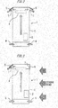
- Figs. 2 to 4 are diagrams illustrating longitudinal sections of an essential part of the power conversion device according to the first embodiment of the present invention.
- each of the plurality of power conversion devices 1 includes a power conversion unit 2, a housing 3, a fan 4, and a pair of covers 5.
- an input part of the power conversion unit 2 is electrically connected to an output part of a solar panel (not illustrated).
- an output part of the power conversion unit 2 is electrically connected to a power system (not illustrated).
- the outer shape of the housing 3 is formed into a rectangular parallelepiped shape.
- the housing 3 accommodates the power conversion unit 2.
- the housing 3 accommodates the power conversion unit 2 on one side thereof.
- the housing 3 has a pair of air inlets 6 and a pair of air outlets 7.
- One of the pair of air inlets 6 is provided at a lower portion on the front side of the housing 3.
- one of the pair of air inlets 6 is formed into a rectangular shape.
- one of the pair of air inlets 6 has its longer direction as the horizontal direction.
- the other of the pair of air inlets 6 is provided at a lower portion on the rear side of the housing 3.
- the other of the pair of air inlets 6 is formed into a rectangular shape.
- the other of the pair of air inlets 6 has its longer direction as the horizontal direction.
- One of the pair of air outlets 7 is provided at an upper portion on the front side of the housing 3.
- one of the pair of air outlets 7 is formed into a rectangular shape.
- one of the pair of air outlets 7 has its longer direction as the horizontal direction.
- the other of the pair of air outlets 7 is provided at an upper portion on the rear side of the housing 3.
- the other of the pair of air outlets 7 is formed into a rectangular shape.
- the other of the pair of air outlets 7 has its longer direction as the horizontal direction.
- the fan 4 is provided inside the housing 3.
- the fan 4 is provided just under an upper surface of the housing 3.
- One of the pair of covers 5 is provided at one of the pair of air outlets 7. For example, an upper edge of one of the pair of covers 5 is supported to be rotatable with respect to the housing 3.
- the other of the pair of covers 5 is provided at the other of the pair of air outlets 7.
- an upper edge of the other of the pair of covers 5 is supported to be rotatable with respect to the housing 3.
- the power conversion unit 2 performs power conversion.
- the power conversion unit 2 receives DC power from the solar panel.
- the power conversion unit 2 converts the DC power into AC power.
- the power conversion unit 2 supplies the AC power to the power system.
- the fan 4 generates airflow.
- outside air flows into the housing 3 via the pair of air inlets 6.
- the air passes through the fan 4.
- the air moves toward the pair of air outlets 7.
- the generated airflow is stronger than airflow moving from the outside of the housing 3 toward one of the pair of air outlets 7.
- the generated airflow is stronger than airflow moving from the outside of the housing 3 toward the other of the pair of air outlets 7.
- one of the pair of covers 5 is pushed toward the outside of the housing 3 by the airflow.
- one of the pair of covers 5 rotates about its upper edge. Therefore, one of the pair of covers 5 is brought into an opened state with respect to one of the pair of air outlets 7. In this state, the airflow flows to the outside of the housing 3 via one of the pair of air outlets 7.
- the other of the pair of covers 5 is pushed toward the outside of the housing 3 by the airflow.
- the other of the pair of covers 5 rotates about its upper edge. Therefore, the other of the pair of covers 5 is brought into an opened state with respect to the other of the pair of air outlets 7. In this state, the airflow flows to the outside of the housing 3 via the other of the pair of air outlets 7.
- one of the pair of covers 5 is pushed toward the inside of the housing 3 by the wind.
- one of the pair of covers 5 is pressed against one of the pair of air outlets 7. Therefore, one of the pair of covers 5 is brought into a closed state with respect to one of the pair of air outlets 7. In this state, the airflow does not go out via one of the pair of air outlets 7 to the outside of the housing 3.
- the other of the pair of covers 5 is pushed toward the outside of the housing 3 by the airflow.
- the other of the pair of covers 5 rotates about its upper edge. Therefore, the other of the pair of covers 5 is brought into an opened state with respect to the other of the pair of air outlets 7. In this state, the airflow goes out via the other of the pair of air outlets 7 to the outside of the housing 3.
- one of the pair of covers 5 is pushed toward the outside of the housing 3 by the airflow.
- one of the pair of covers 5 rotates about its upper edge. Therefore, one of the pair of covers 5 is brought into an opened state with respect to one of the pair of air outlets 7. In this case, part of the airflow goes out via one of the pair of air outlets 7 to the outside of the housing 3.
- the other of the pair of covers 5 is pushed toward the inside of the housing 3 by the wind. As a result, the other of the pair of covers 5 is pressed against the other of the pair of air outlets 7. Therefore, the other of the pair of covers 5 is brought into a closed state with respect to the other of the pair of air outlets 7. In this case, the airflow does not go out via the other of the pair of air outlets 7 to the outside of the housing 3.
- the cover 5 when the airflow from the fan 4 is weaker than the airflow moving from the outside of the housing 3 toward the air outlet 7 of the housing 3, the cover 5 is brought into a closed state with respect to the air outlet 7. Therefore, it is possible to suppress air from flowing back into the housing 3 without increasing the rotation speed of the fan 4.
- the power conversion device 1 that is highly reliable and low in cost can be realized.
- Figs. 5 and 6 are diagrams each illustrating a longitudinal section of an essential part of a power conversion device according to a second embodiment of the present invention.
- the same or corresponding parts as those in the first embodiment are denoted by the same reference numerals. Explanations of these parts will be omitted.
- the power conversion device 1 does not have the covers 5.
- the power conversion device 1 includes a wind speed measurement device 8 and a control device 9.
- the wind speed measurement device 8 is provided outside the housing 3.
- the wind speed measurement device 8 is provided on the upper surface of the housing 3.
- the control device 9 is provided inside the housing 3.
- the control device 9 is provided on the other side of the housing 3.
- An input part of the control device 9 is electrically connected to an output part of the wind speed measurement device 8.
- An output part of the control device 9 is electrically connected to an input part of the fan 4.
- the wind speed measurement device 8 measures the wind speed outside the housing 3.
- the control device 9 controls the rotation speed of the fan 4 based on the wind speed.
- the control device 9 increases the rotation speed of the fan 4. As a result, an appropriate amount of air flows out via the pair of air outlets 7 to the outside of the housing 3.
- the control device 9 decreases the rotation speed of the fan 4. As a result, an appropriate amount of air flows out via the pair of air outlets 7 to the outside of the housing 3.
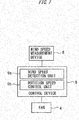
- control device 9 will be described with reference to Fig. 7 .
- Fig. 7 is a block diagram illustrating the control device of the power conversion device according to the second embodiment of the present invention.
- the control device 9 includes a wind speed detection unit 9a and a rotation speed control unit 9b.
- the wind speed detection unit 9a detects the wind speed measured by the wind speed measurement device 8.
- the rotation speed control unit 9b controls the rotation speed of the fan 4 based on the wind speed detected by the wind speed detection unit 9a.
- control device 9 Next, an operation of the control device 9 will be schematically illustrated with reference to Fig. 8 .
- Fig. 8 is a flowchart schematically illustrating the operation of the control device of the power conversion device according to the second embodiment of the present invention.
- step S1 the control device 9 determines whether the wind speed measurement device 8 has measured the wind speed. When the wind speed measurement device 8 has not measured the wind speed in step S1, the control device 9 performs the operation of step S1. When the wind speed measurement device 8 has measured the wind speed in step S1, the control device 9 performs an operation of step S2.
- step S2 the control device 9 determines whether the wind speed measured by the wind speed measurement device 8 has increased.
- step S2 When the wind speed measured by the wind speed measurement device 8 has not increased in step S2, the control device 9 performs an operation of step S3. In step S3, the control device 9 determines whether the wind speed measured by the wind speed measurement device 8 has decreased.
- step S3 When the wind speed measured by the wind speed measurement device 8 has not decreased in step S3, the control device 9 performs an operation of step S4. In step S4, the control device 9 maintains the rotation speed of the fan 4. Subsequently, the control device 9 performs the operation of step S2.
- step S5 When the wind speed measured by the wind speed measurement device 8 has increased in step S2, the control device 9 performs an operation of step S5. In step S5, the control device 9 increases the rotation speed of the fan 4. Subsequently, the control device 9 performs the operation of step S2.
- step S3 When the wind speed measured by the wind speed measurement device 8 has decreased in step S3, the control device 9 performs an operation of step S6. In step S6, the control device 9 decreases the rotation speed of the fan 4. Subsequently, the control device 9 performs the operation of step S2.
- the control device 9 controls the rotation speed of the fan 4 based on the wind speed. Therefore, it is possible to suppress air from flowing back into the housing 3 without excessively increasing the rotation speed of the fan 4. As a result, the lifetime of the fan 4 can also be prolonged.
- control device 9 Next, an example of the control device 9 will be described with reference to Fig. 9 .
- Fig. 9 is a diagram illustrating a hardware configuration of the control device of the power conversion device according to the second embodiment of the present invention.
- Each function of the control device 9 can be realized by a processing circuitry.
- the processing circuitry includes at least one processor 10a and at least one memory 10b.
- the processing circuitry includes at least one dedicated hardware 11.
- each function of the control device 9 can be realized by software, firmware, or a combination of software and firmware. At least one of the software and the firmware is described as a program. At least one of the software and the firmware is stored in the at least one memory 10b.
- the at least one processor 10a realizes each function of the control device 9 by reading and executing the program stored in the at least one memory 10b.
- the at least one processor 10a may be referred to as a central processing unit (CPU), a central processor, a processor, an arithmetic unit, a microprocessor, a microcomputer, or a DSP.
- the at least one memory 10b is a nonvolatile or volatile semiconductor memory such as RAM, ROM, flash memory, EPROM, or EEPROM, a magnetic disk, a flexible disk, an optical disk, a compact disk, a mini disk, a DVD, or the like.
- the processing circuitry can be realized by, for example, a single circuit, a composite circuit, a programmed processor, a parallel programmed processor, ASIC, FPGA, or a combination thereof.
- each function of the control device 9 can be respectively realized by the processing circuitry.
- each function of the control device 9 can be collectively realized by the processing circuitry.
- Part of each function of the control device 9 may be realized by the dedicated hardware 11 and the rest may be realized by software or firmware.
- functions of the wind speed detection unit 9a may be realized by the processing circuitry as the dedicated hardware 11, and functions other the functions of the wind speed detection unit 9a may be realized by the at least one processor 10a reading and executing the program stored in the at least one memory 10b.
- the processing circuitry realizes each function of the control device 9 by the hardware 11, software, firmware, or a combination thereof.
- control device 9 according to the second embodiment may be used. In this case, even when the cover 5 is broken, it is possible to suppress air from flowing back into the housing 3 without excessively increasing the rotation speed of the fan 4.
- the positions of the air inlets 6 and the air outlets 7 may be appropriately set.
- the air inlets 6 may be provided at an upper portion of the housing 3.
- the air outlets 7 may be provided at a lower portion of the housing 3. In this case, inflow of dusts from the ground can be prevented.
- the power conversion device according to the present invention can be used for a system suppressing air from flowing back into the housing.
Landscapes
- Engineering & Computer Science (AREA)
- Microelectronics & Electronic Packaging (AREA)
- Physics & Mathematics (AREA)
- Thermal Sciences (AREA)
- Power Engineering (AREA)
- Theoretical Computer Science (AREA)
- Human Computer Interaction (AREA)
- General Engineering & Computer Science (AREA)
- General Physics & Mathematics (AREA)
- Inverter Devices (AREA)
- Cooling Or The Like Of Electrical Apparatus (AREA)
Abstract
Description
- The present invention relates to a power conversion device.
-
PTL 1 discloses a power conversion device. The power conversion device includes a power conversion unit and a fan. The power conversion unit performs power conversion. A housing accommodates the power conversion unit. The fan generates airflow by rotating. The power conversion unit is cooled by the airflow. - [PTL 1]
JP 2012-005242 A - However, when the power conversion device discussed in
PTL 1 is provided outdoors, wind from the outside of the housing may flow back into the housing. In this case, the power conversion unit is not cooled appropriately. - The present invention has been made to solve the above-mentioned problem. An object of the present invention is to provide a power conversion device capable of suppressing backflow of air into the housing.
- A power conversion device according to the present invention includes a power conversion unit configured to perform power conversion, a housing accommodating the power conversion and having an air inlet and an air outlet, a fan provided inside the housing to generate airflow in such a manner that air flows to the outside of the housing via the air outlet after flowing into the housing via the air inlet, and a cover provided at the air outlet, the cover being configured to be brought into an opened state with respect to the air outlet if the airflow generated by the fan is stronger than airflow moving from the outside of the housing toward the air outlet, and to be brought into a closed state with respect to the air outlet if the airflow generated by the fan is weaker than the airflow moving from the outside of the housing toward the exhaust of the housing.
- A power conversion device according to the present invention includes a power conversion unit configured to perform power conversion, a housing accommodating the power conversion and having an air inlet and an air outlet, a fan provided inside the housing to generate airflow in such a manner that air flows to the outside of the housing via the air outlet after flowing into the housing via the air inlet, a wind speed measurement device configured to measure the wind speed outside the housing, and a control device configured to, when the wind speed measurement device has measured the wind speed, control the rotation speed of the fan based on the wind speed.
- According to these inventions, the airflow from the fan is variable depending on wind outside the housing. Therefore, it is possible to suppress air from flowing back into the housing.
-
-
Fig. 1 is a perspective view illustrating a power conversion device according to a first embodiment of the present invention. -
Fig. 2 is a diagram illustrating a longitudinal section of an essential part of the power conversion device according to the first embodiment of the present invention. -
Fig. 3 is a diagram illustrating a longitudinal section of the essential part of the power conversion device according to the first embodiment of the present invention. -
Fig. 4 is a diagram illustrating a longitudinal section of the essential part of the power conversion device according to the first embodiment of the present invention. -
Fig. 5 is a diagram illustrating a longitudinal section of an essential part of a power conversion device according to a second embodiment of the present invention. -
Fig. 6 is a diagram illustrating a longitudinal section of the essential part of the power conversion device according to the second embodiment of the present invention. -
Fig. 7 is a block diagram illustrating a control device of the power conversion device according to the second embodiment of the present invention. -
Fig. 8 is a flowchart schematically illustrating an operation of the control device of the power conversion device according to the second embodiment of the present invention. -
Fig. 9 is a diagram illustrating a hardware configuration of the control device of the power conversion device according to the second embodiment of the present invention. - Embodiments of the present invention will be described with reference to attached drawings. In the drawings, the same or corresponding parts are denoted by the same reference numerals. Duplicated explanations of these parts will be simplified or omitted appropriately.
-
Fig. 1 is a perspective view illustrating a power conversion device according to a first embodiment of the present invention. - In
Fig. 1 , a plurality ofpower conversion devices 1 is provided outdoors. The pluralpower conversion devices 1 are adjacent to each other. - Next, airflow will be described with reference to
Figs. 2 to 4 . -
Figs. 2 to 4 are diagrams illustrating longitudinal sections of an essential part of the power conversion device according to the first embodiment of the present invention. - As illustrated in
Fig. 2 , each of the plurality ofpower conversion devices 1 includes apower conversion unit 2, ahousing 3, afan 4, and a pair ofcovers 5. - For example, an input part of the
power conversion unit 2 is electrically connected to an output part of a solar panel (not illustrated). For example, an output part of thepower conversion unit 2 is electrically connected to a power system (not illustrated). - For example, the outer shape of the
housing 3 is formed into a rectangular parallelepiped shape. Thehousing 3 accommodates thepower conversion unit 2. For example, thehousing 3 accommodates thepower conversion unit 2 on one side thereof. For example, thehousing 3 has a pair ofair inlets 6 and a pair ofair outlets 7. - One of the pair of
air inlets 6 is provided at a lower portion on the front side of thehousing 3. For example, one of the pair ofair inlets 6 is formed into a rectangular shape. For example, one of the pair ofair inlets 6 has its longer direction as the horizontal direction. The other of the pair ofair inlets 6 is provided at a lower portion on the rear side of thehousing 3. For example, the other of the pair ofair inlets 6 is formed into a rectangular shape. For example, the other of the pair ofair inlets 6 has its longer direction as the horizontal direction. - One of the pair of
air outlets 7 is provided at an upper portion on the front side of thehousing 3. For example, one of the pair ofair outlets 7 is formed into a rectangular shape. For example, one of the pair ofair outlets 7 has its longer direction as the horizontal direction. The other of the pair ofair outlets 7 is provided at an upper portion on the rear side of thehousing 3. For example, the other of the pair ofair outlets 7 is formed into a rectangular shape. For example, the other of the pair ofair outlets 7 has its longer direction as the horizontal direction. - The
fan 4 is provided inside thehousing 3. For example, thefan 4 is provided just under an upper surface of thehousing 3. - One of the pair of
covers 5 is provided at one of the pair ofair outlets 7. For example, an upper edge of one of the pair ofcovers 5 is supported to be rotatable with respect to thehousing 3. The other of the pair ofcovers 5 is provided at the other of the pair ofair outlets 7. For example, an upper edge of the other of the pair ofcovers 5 is supported to be rotatable with respect to thehousing 3. - In each
power conversion device 1, thepower conversion unit 2 performs power conversion. For example, thepower conversion unit 2 receives DC power from the solar panel. Thepower conversion unit 2 converts the DC power into AC power. Thepower conversion unit 2 supplies the AC power to the power system. - At this time, the
fan 4 generates airflow. As a result, outside air flows into thehousing 3 via the pair ofair inlets 6. Subsequently, the air passes through thefan 4. Thereafter, the air moves toward the pair ofair outlets 7. - In a normal state, the generated airflow is stronger than airflow moving from the outside of the
housing 3 toward one of the pair ofair outlets 7. The generated airflow is stronger than airflow moving from the outside of thehousing 3 toward the other of the pair ofair outlets 7. - At this time, at one of the pair of
air outlets 7, one of the pair ofcovers 5 is pushed toward the outside of thehousing 3 by the airflow. As a result, one of the pair ofcovers 5 rotates about its upper edge. Therefore, one of the pair ofcovers 5 is brought into an opened state with respect to one of the pair ofair outlets 7. In this state, the airflow flows to the outside of thehousing 3 via one of the pair ofair outlets 7. - At the other of the pair of
air outlets 7, the other of the pair ofcovers 5 is pushed toward the outside of thehousing 3 by the airflow. As a result, the other of the pair ofcovers 5 rotates about its upper edge. Therefore, the other of the pair ofcovers 5 is brought into an opened state with respect to the other of the pair ofair outlets 7. In this state, the airflow flows to the outside of thehousing 3 via the other of the pair ofair outlets 7. - As illustrated in
Fig. 3 , in a case where wind from the front side of thehousing 3 is strong, the above-mentioned airflow is weaker than airflow moving from the outside of thehousing 3 toward one of the pair ofair outlets 7. - At this time, at one of the pair of
air outlets 7, one of the pair ofcovers 5 is pushed toward the inside of thehousing 3 by the wind. As a result, one of the pair ofcovers 5 is pressed against one of the pair ofair outlets 7. Therefore, one of the pair ofcovers 5 is brought into a closed state with respect to one of the pair ofair outlets 7. In this state, the airflow does not go out via one of the pair ofair outlets 7 to the outside of thehousing 3. - At the other of the pair of
air outlets 7, the other of the pair ofcovers 5 is pushed toward the outside of thehousing 3 by the airflow. As a result, the other of the pair ofcovers 5 rotates about its upper edge. Therefore, the other of the pair ofcovers 5 is brought into an opened state with respect to the other of the pair ofair outlets 7. In this state, the airflow goes out via the other of the pair ofair outlets 7 to the outside of thehousing 3. - As illustrated in
Fig. 4 , in a case where wind from the rear side of thehousing 3 is strong, the above-mentioned airflow is weaker than airflow moving from the outside of thehousing 3 toward the other of the pair ofair outlets 7. - At this time, at one of the pair of
air outlets 7, one of the pair ofcovers 5 is pushed toward the outside of thehousing 3 by the airflow. As a result, one of the pair ofcovers 5 rotates about its upper edge. Therefore, one of the pair ofcovers 5 is brought into an opened state with respect to one of the pair ofair outlets 7. In this case, part of the airflow goes out via one of the pair ofair outlets 7 to the outside of thehousing 3. - At the other of the pair of
air outlets 7, the other of the pair ofcovers 5 is pushed toward the inside of thehousing 3 by the wind. As a result, the other of the pair ofcovers 5 is pressed against the other of the pair ofair outlets 7. Therefore, the other of the pair ofcovers 5 is brought into a closed state with respect to the other of the pair ofair outlets 7. In this case, the airflow does not go out via the other of the pair ofair outlets 7 to the outside of thehousing 3. - According to the first embodiment described above, when the airflow from the
fan 4 is weaker than the airflow moving from the outside of thehousing 3 toward theair outlet 7 of thehousing 3, thecover 5 is brought into a closed state with respect to theair outlet 7. Therefore, it is possible to suppress air from flowing back into thehousing 3 without increasing the rotation speed of thefan 4. - At this time, no active device such as an actuator is required. Therefore, the
power conversion device 1 that is highly reliable and low in cost can be realized. -
Figs. 5 and 6 are diagrams each illustrating a longitudinal section of an essential part of a power conversion device according to a second embodiment of the present invention. In the drawings, the same or corresponding parts as those in the first embodiment are denoted by the same reference numerals. Explanations of these parts will be omitted. - As illustrated in
Figs. 5 and 6 , in the second embodiment, thepower conversion device 1 does not have thecovers 5. Thepower conversion device 1 includes a windspeed measurement device 8 and acontrol device 9. - The wind
speed measurement device 8 is provided outside thehousing 3. For example, the windspeed measurement device 8 is provided on the upper surface of thehousing 3. Thecontrol device 9 is provided inside thehousing 3. For example, thecontrol device 9 is provided on the other side of thehousing 3. An input part of thecontrol device 9 is electrically connected to an output part of the windspeed measurement device 8. An output part of thecontrol device 9 is electrically connected to an input part of thefan 4. - The wind
speed measurement device 8 measures the wind speed outside thehousing 3. When the windspeed measurement device 8 measures the wind speed, thecontrol device 9 controls the rotation speed of thefan 4 based on the wind speed. - For example, as illustrated in
Fig. 5 , when the wind speed increases, thecontrol device 9 increases the rotation speed of thefan 4. As a result, an appropriate amount of air flows out via the pair ofair outlets 7 to the outside of thehousing 3. - For example, as illustrated in
Fig. 6 , when the wind speed decreases, thecontrol device 9 decreases the rotation speed of thefan 4. As a result, an appropriate amount of air flows out via the pair ofair outlets 7 to the outside of thehousing 3. - Next, the
control device 9 will be described with reference toFig. 7 . -
Fig. 7 is a block diagram illustrating the control device of the power conversion device according to the second embodiment of the present invention. - As illustrated in
Fig. 7 , thecontrol device 9 includes a windspeed detection unit 9a and a rotationspeed control unit 9b. - The wind
speed detection unit 9a detects the wind speed measured by the windspeed measurement device 8. The rotationspeed control unit 9b controls the rotation speed of thefan 4 based on the wind speed detected by the windspeed detection unit 9a. - Next, an operation of the
control device 9 will be schematically illustrated with reference toFig. 8 . -
Fig. 8 is a flowchart schematically illustrating the operation of the control device of the power conversion device according to the second embodiment of the present invention. - In step S1, the
control device 9 determines whether the windspeed measurement device 8 has measured the wind speed. When the windspeed measurement device 8 has not measured the wind speed in step S1, thecontrol device 9 performs the operation of step S1. When the windspeed measurement device 8 has measured the wind speed in step S1, thecontrol device 9 performs an operation of step S2. - In step S2, the
control device 9 determines whether the wind speed measured by the windspeed measurement device 8 has increased. - When the wind speed measured by the wind
speed measurement device 8 has not increased in step S2, thecontrol device 9 performs an operation of step S3. In step S3, thecontrol device 9 determines whether the wind speed measured by the windspeed measurement device 8 has decreased. - When the wind speed measured by the wind
speed measurement device 8 has not decreased in step S3, thecontrol device 9 performs an operation of step S4. In step S4, thecontrol device 9 maintains the rotation speed of thefan 4. Subsequently, thecontrol device 9 performs the operation of step S2. - When the wind speed measured by the wind
speed measurement device 8 has increased in step S2, thecontrol device 9 performs an operation of step S5. In step S5, thecontrol device 9 increases the rotation speed of thefan 4. Subsequently, thecontrol device 9 performs the operation of step S2. - When the wind speed measured by the wind
speed measurement device 8 has decreased in step S3, thecontrol device 9 performs an operation of step S6. In step S6, thecontrol device 9 decreases the rotation speed of thefan 4. Subsequently, thecontrol device 9 performs the operation of step S2. - According to the second embodiment described above, when the wind
speed measurement device 8 has measured the wind speed, thecontrol device 9 controls the rotation speed of thefan 4 based on the wind speed. Therefore, it is possible to suppress air from flowing back into thehousing 3 without excessively increasing the rotation speed of thefan 4. As a result, the lifetime of thefan 4 can also be prolonged. - Next, an example of the
control device 9 will be described with reference toFig. 9 . -
Fig. 9 is a diagram illustrating a hardware configuration of the control device of the power conversion device according to the second embodiment of the present invention. - Each function of the
control device 9 can be realized by a processing circuitry. For example, the processing circuitry includes at least oneprocessor 10a and at least onememory 10b. For example, the processing circuitry includes at least onededicated hardware 11. - When the processing circuitry includes the at least one
processor 10a and the at least onememory 10b, each function of thecontrol device 9 can be realized by software, firmware, or a combination of software and firmware. At least one of the software and the firmware is described as a program. At least one of the software and the firmware is stored in the at least onememory 10b. The at least oneprocessor 10a realizes each function of thecontrol device 9 by reading and executing the program stored in the at least onememory 10b. The at least oneprocessor 10a may be referred to as a central processing unit (CPU), a central processor, a processor, an arithmetic unit, a microprocessor, a microcomputer, or a DSP. For example, the at least onememory 10b is a nonvolatile or volatile semiconductor memory such as RAM, ROM, flash memory, EPROM, or EEPROM, a magnetic disk, a flexible disk, an optical disk, a compact disk, a mini disk, a DVD, or the like. - When the processing circuitry includes the at least one
dedicated hardware 11, the processing circuitry can be realized by, for example, a single circuit, a composite circuit, a programmed processor, a parallel programmed processor, ASIC, FPGA, or a combination thereof. For example, each function of thecontrol device 9 can be respectively realized by the processing circuitry. For example, each function of thecontrol device 9 can be collectively realized by the processing circuitry. - Part of each function of the
control device 9 may be realized by thededicated hardware 11 and the rest may be realized by software or firmware. For example, functions of the windspeed detection unit 9a may be realized by the processing circuitry as thededicated hardware 11, and functions other the functions of the windspeed detection unit 9a may be realized by the at least oneprocessor 10a reading and executing the program stored in the at least onememory 10b. - In this manner, the processing circuitry realizes each function of the
control device 9 by thehardware 11, software, firmware, or a combination thereof. - In the
power conversion device 1 described in the first embodiment, thecontrol device 9 according to the second embodiment may be used. In this case, even when thecover 5 is broken, it is possible to suppress air from flowing back into thehousing 3 without excessively increasing the rotation speed of thefan 4. - Further, the positions of the
air inlets 6 and theair outlets 7 may be appropriately set. For example, theair inlets 6 may be provided at an upper portion of thehousing 3. At this time, theair outlets 7 may be provided at a lower portion of thehousing 3. In this case, inflow of dusts from the ground can be prevented. - As mentioned above, the power conversion device according to the present invention can be used for a system suppressing air from flowing back into the housing.
-
- 1
- Power conversion device
- 2
- Power conversion unit
- 3
- Housing
- 4
- Fan
- 5
- Cover
- 6
- Air inlet
- 7
- Air outlet
- 8
- Wind speed measurement device
- 9
- Control device
- 9a
- Wind speed detection unit
- 9b
- Rotation speed control unit
- 10a
- Processor
- 10b
- Memory
- 11
- Hardware
Claims (3)
- A power conversion device comprising:a power conversion unit configured to perform power conversion;a housing accommodating the power conversion and having an air inlet and an air outlet,a fan provided inside the housing to generate airflow in such a manner that air flows to outside of the housing via the air outlet after flowing into the housing via the air inlet; anda cover provided at the air outlet, the cover being configured to be brought into an opened state with respect to the air outlet if the airflow generated by the fan is stronger than airflow moving from the outside of the housing toward the air outlet, and to be brought into a closed state with respect to the air outlet if the airflow generated by the fan is weaker than the airflow moving from the outside of the housing toward the exhaust of the housing.
- The power conversion device according to claim 1, further comprising:a wind speed measurement device configured to measure a wind speed outside the housing, anda control device configured to, when the wind speed measurement device has measured the wind speed, control the rotation speed of the fan based on the wind speed.
- A power conversion device comprising:a power conversion unit configured to perform power conversion,a housing accommodating the power conversion and having an air inlet and an air outlet,a fan provided inside the housing to generate airflow in such a manner that air flows to the outside of the housing via the air outlet after flowing into the housing via the air inlet,a wind speed measurement device configured to measure a wind speed outside the housing, anda control device configured to, when the wind speed measurement device has measured the wind speed, control the rotation speed of the fan based on the wind speed.
Applications Claiming Priority (1)
| Application Number | Priority Date | Filing Date | Title |
|---|---|---|---|
| PCT/JP2016/085170 WO2018096677A1 (en) | 2016-11-28 | 2016-11-28 | Power conversion device |
Publications (2)
| Publication Number | Publication Date |
|---|---|
| EP3547524A1 true EP3547524A1 (en) | 2019-10-02 |
| EP3547524A4 EP3547524A4 (en) | 2020-11-11 |
Family
ID=62195091
Family Applications (1)
| Application Number | Title | Priority Date | Filing Date |
|---|---|---|---|
| EP16922473.0A Pending EP3547524A4 (en) | 2016-11-28 | 2016-11-28 | CURRENT CONVERSION DEVICE |
Country Status (5)
| Country | Link |
|---|---|
| US (1) | US11134592B2 (en) |
| EP (1) | EP3547524A4 (en) |
| JP (1) | JP6696588B2 (en) |
| CN (1) | CN110073586A (en) |
| WO (1) | WO2018096677A1 (en) |
Families Citing this family (2)
| Publication number | Priority date | Publication date | Assignee | Title |
|---|---|---|---|---|
| JP7660082B2 (en) * | 2022-03-09 | 2025-04-10 | 株式会社Tmeic | Power conversion unit and power system |
| CN114721485A (en) * | 2022-04-29 | 2022-07-08 | 苏州浪潮智能科技有限公司 | Server wind scooper and server |
Family Cites Families (27)
| Publication number | Priority date | Publication date | Assignee | Title |
|---|---|---|---|---|
| JPH03175484A (en) * | 1989-12-04 | 1991-07-30 | Mitsubishi Electric Corp | Air ventilation device for box body |
| JP2001317772A (en) * | 2000-05-11 | 2001-11-16 | Matsushita Refrig Co Ltd | Air conditioning system for stores |
| JP2003070259A (en) | 2001-08-27 | 2003-03-07 | Kyocera Corp | Power converter for outdoor installation |
| JP4066657B2 (en) * | 2001-12-27 | 2008-03-26 | 株式会社明電舎 | Outdoor board |
| JP2004281489A (en) * | 2003-03-13 | 2004-10-07 | Toshiba Corp | Self-cooling power converter |
| CN1895010A (en) * | 2003-08-27 | 2007-01-10 | 珀塞尔系统公司 | Internal environmental control system and its usage |
| JP2007250596A (en) * | 2006-03-13 | 2007-09-27 | Nec Saitama Ltd | Outdoor installation type base station equipment with wind pressure opening and closing louver |
| JP2008103637A (en) * | 2006-10-20 | 2008-05-01 | Nec Corp | Wireless communication base station apparatus and method of preventing dust invasion |
| JP5260347B2 (en) * | 2009-02-06 | 2013-08-14 | 日立オートモティブシステムズ株式会社 | Power converter |
| US20100291850A1 (en) * | 2009-05-05 | 2010-11-18 | Mike Sabbaghian | Variable Volume Air-Flow Exhaust System |
| DE102009037567B4 (en) * | 2009-08-14 | 2011-09-22 | Sinitec Vertriebsgesellschaft Mbh | Cooling arrangement, server rack and method for controlling a cooling arrangement |
| FR2951275B1 (en) * | 2009-10-09 | 2012-11-02 | Epsiline | DEVICE FOR MEASURING WIND SPEED |
| MX2012005997A (en) * | 2009-11-30 | 2012-07-25 | Emerson Network Power Energy | Outdoor electronic equipment enclosures and related methods. |
| JP5474674B2 (en) | 2010-06-17 | 2014-04-16 | 東芝三菱電機産業システム株式会社 | Power converter |
| JP5803327B2 (en) | 2011-06-27 | 2015-11-04 | 富士電機株式会社 | Inverter device waterproof cover |
| JP5870268B2 (en) * | 2011-12-14 | 2016-02-24 | パナソニックIpマネジメント株式会社 | Power conversion unit |
| US9292023B2 (en) * | 2012-09-12 | 2016-03-22 | International Business Machines Corporation | Decreasing the internal temperature of a computer in response to corrosion |
| CN203010850U (en) * | 2012-12-28 | 2013-06-19 | 海信(山东)空调有限公司 | Control circuit of air conditioner outdoor fan and air conditioner |
| JP2014017517A (en) * | 2013-09-30 | 2014-01-30 | Fujitsu Ltd | Backflow prevention device, electronic system, and method for manufacturing backflow prevention device |
| JP2016032367A (en) * | 2014-07-29 | 2016-03-07 | 株式会社安川電機 | Power converter |
| CN104582380A (en) * | 2014-12-04 | 2015-04-29 | 重庆科川电气有限公司 | Self-sealing rainproof frequency converter |
| CN204376682U (en) * | 2014-12-04 | 2015-06-03 | 重庆科川电气有限公司 | Self-closed type dustproof transducer |
| JP2016146737A (en) * | 2015-02-03 | 2016-08-12 | パナソニックIpマネジメント株式会社 | Cooling apparatus |
| JP6449678B2 (en) * | 2015-02-24 | 2019-01-09 | Necプラットフォームズ株式会社 | Electronic equipment |
| CN205377633U (en) * | 2015-12-23 | 2016-07-06 | 天津亚陆海东电器设备有限公司 | Closed structure converter with rain -proof function |
| CN105650022B (en) | 2016-03-29 | 2017-09-22 | 海信集团有限公司 | A kind of fan rotational frequency control method and fan rotation speed control apparatus |
| EP3468025B1 (en) * | 2016-06-01 | 2022-01-05 | Mitsubishi Electric Corporation | Power conversion device |
-
2016
- 2016-11-28 CN CN201680091093.0A patent/CN110073586A/en active Pending
- 2016-11-28 WO PCT/JP2016/085170 patent/WO2018096677A1/en not_active Ceased
- 2016-11-28 US US16/348,989 patent/US11134592B2/en active Active
- 2016-11-28 EP EP16922473.0A patent/EP3547524A4/en active Pending
- 2016-11-28 JP JP2018552370A patent/JP6696588B2/en active Active
Also Published As
| Publication number | Publication date |
|---|---|
| JPWO2018096677A1 (en) | 2019-10-17 |
| CN110073586A (en) | 2019-07-30 |
| JP6696588B2 (en) | 2020-05-20 |
| US20190274236A1 (en) | 2019-09-05 |
| WO2018096677A1 (en) | 2018-05-31 |
| US11134592B2 (en) | 2021-09-28 |
| EP3547524A4 (en) | 2020-11-11 |
Similar Documents
| Publication | Publication Date | Title |
|---|---|---|
| EP2894346B1 (en) | Molecular pump | |
| JP6064958B2 (en) | Fuel cell system for electric vehicle and control method thereof | |
| JP6776796B2 (en) | Current transformer mounting diagnostic device and current transformer mounting diagnostic method | |
| EP3185408A1 (en) | Motor inverter with temperature dependent modes of operation | |
| US11134592B2 (en) | Power conversion device | |
| MX387031B (en) | ELECTRICAL DEVICE WITH FILTER MESH BLOCKAGE DETECTION FUNCTION. | |
| CN104568698B (en) | The detection means and method of filter network state in air conditioner | |
| JP6428042B2 (en) | Motor control device | |
| US20200014188A1 (en) | Arc detection circuit, switch system, power conditioner system and arc detection method | |
| US10060982B2 (en) | Detecting faults in motors and drives | |
| EP3450867A1 (en) | Air conditioner | |
| CN111066215B (en) | Power conversion device | |
| US20150180383A1 (en) | Air blower equipped with brushless dc motor | |
| JP6858441B2 (en) | Plasma reactor anomaly detector | |
| JP2017203565A (en) | Air blower | |
| CN110785905B (en) | Control device for power conversion device | |
| EP2579114A3 (en) | Use of motor protection system to assist in determining power plant metrics | |
| CN113165527A (en) | High-voltage device for operating high-voltage applications | |
| CN104854747B (en) | Limit-Based Threshold Estimation for Premonition and Health Management | |
| JP2015083889A (en) | Ventilation device and ventilation system | |
| JP6798397B2 (en) | Electrical system | |
| EP2713056A3 (en) | Blower assembly for electronic device | |
| CN114556765A (en) | Control device for power conversion system | |
| EP3633835B1 (en) | Power conversion device | |
| TWI647888B (en) | Ion generating device and ion generator |
Legal Events
| Date | Code | Title | Description |
|---|---|---|---|
| STAA | Information on the status of an ep patent application or granted ep patent |
Free format text: STATUS: THE INTERNATIONAL PUBLICATION HAS BEEN MADE |
|
| PUAI | Public reference made under article 153(3) epc to a published international application that has entered the european phase |
Free format text: ORIGINAL CODE: 0009012 |
|
| STAA | Information on the status of an ep patent application or granted ep patent |
Free format text: STATUS: REQUEST FOR EXAMINATION WAS MADE |
|
| 17P | Request for examination filed |
Effective date: 20190516 |
|
| AK | Designated contracting states |
Kind code of ref document: A1 Designated state(s): AL AT BE BG CH CY CZ DE DK EE ES FI FR GB GR HR HU IE IS IT LI LT LU LV MC MK MT NL NO PL PT RO RS SE SI SK SM TR |
|
| AX | Request for extension of the european patent |
Extension state: BA ME |
|
| DAV | Request for validation of the european patent (deleted) | ||
| DAX | Request for extension of the european patent (deleted) | ||
| RIC1 | Information provided on ipc code assigned before grant |
Ipc: H02M 7/48 20070101AFI20200706BHEP Ipc: H05K 7/20 20060101ALI20200706BHEP |
|
| A4 | Supplementary search report drawn up and despatched |
Effective date: 20201013 |
|
| RIC1 | Information provided on ipc code assigned before grant |
Ipc: H02M 7/48 20070101AFI20201007BHEP Ipc: H05K 7/20 20060101ALI20201007BHEP |
|
| STAA | Information on the status of an ep patent application or granted ep patent |
Free format text: STATUS: EXAMINATION IS IN PROGRESS |
|
| 17Q | First examination report despatched |
Effective date: 20221216 |