EP3547493B1 - Lighting system and method for operation of an emergency lighting - Google Patents
Lighting system and method for operation of an emergency lighting Download PDFInfo
- Publication number
- EP3547493B1 EP3547493B1 EP19175646.9A EP19175646A EP3547493B1 EP 3547493 B1 EP3547493 B1 EP 3547493B1 EP 19175646 A EP19175646 A EP 19175646A EP 3547493 B1 EP3547493 B1 EP 3547493B1
- Authority
- EP
- European Patent Office
- Prior art keywords
- operating device
- emergency light
- central unit
- lighting system
- emergency
- Prior art date
- Legal status (The legal status is an assumption and is not a legal conclusion. Google has not performed a legal analysis and makes no representation as to the accuracy of the status listed.)
- Active
Links
- 238000000034 method Methods 0.000 title claims description 15
- 239000004065 semiconductor Substances 0.000 claims description 29
- 238000004891 communication Methods 0.000 claims description 6
- 238000012544 monitoring process Methods 0.000 claims description 6
- 230000008878 coupling Effects 0.000 claims description 5
- 238000010168 coupling process Methods 0.000 claims description 5
- 238000005859 coupling reaction Methods 0.000 claims description 5
- 238000001514 detection method Methods 0.000 claims description 4
- 230000006870 function Effects 0.000 description 60
- 230000008859 change Effects 0.000 description 3
- 238000002955 isolation Methods 0.000 description 3
- 230000009471 action Effects 0.000 description 2
- 239000003990 capacitor Substances 0.000 description 2
- 238000012937 correction Methods 0.000 description 2
- 238000010586 diagram Methods 0.000 description 2
- 238000005265 energy consumption Methods 0.000 description 2
- 238000009434 installation Methods 0.000 description 2
- 238000005259 measurement Methods 0.000 description 2
- 238000012986 modification Methods 0.000 description 2
- 230000004048 modification Effects 0.000 description 2
- 238000005036 potential barrier Methods 0.000 description 2
- 230000000717 retained effect Effects 0.000 description 2
- 230000002426 anti-panic effect Effects 0.000 description 1
- 230000004888 barrier function Effects 0.000 description 1
- 230000005540 biological transmission Effects 0.000 description 1
- 239000004020 conductor Substances 0.000 description 1
- 238000003745 diagnosis Methods 0.000 description 1
- 230000000694 effects Effects 0.000 description 1
- 230000001788 irregular Effects 0.000 description 1
- 238000012423 maintenance Methods 0.000 description 1
- 230000002085 persistent effect Effects 0.000 description 1
- 230000008569 process Effects 0.000 description 1
- 230000004044 response Effects 0.000 description 1
- 230000000630 rising effect Effects 0.000 description 1
Images

Classifications
-
- H—ELECTRICITY
- H02—GENERATION; CONVERSION OR DISTRIBUTION OF ELECTRIC POWER
- H02J—CIRCUIT ARRANGEMENTS OR SYSTEMS FOR SUPPLYING OR DISTRIBUTING ELECTRIC POWER; SYSTEMS FOR STORING ELECTRIC ENERGY
- H02J9/00—Circuit arrangements for emergency or stand-by power supply, e.g. for emergency lighting
- H02J9/04—Circuit arrangements for emergency or stand-by power supply, e.g. for emergency lighting in which the distribution system is disconnected from the normal source and connected to a standby source
- H02J9/06—Circuit arrangements for emergency or stand-by power supply, e.g. for emergency lighting in which the distribution system is disconnected from the normal source and connected to a standby source with automatic change-over, e.g. UPS systems
- H02J9/062—Circuit arrangements for emergency or stand-by power supply, e.g. for emergency lighting in which the distribution system is disconnected from the normal source and connected to a standby source with automatic change-over, e.g. UPS systems for AC powered loads
- H02J9/065—Circuit arrangements for emergency or stand-by power supply, e.g. for emergency lighting in which the distribution system is disconnected from the normal source and connected to a standby source with automatic change-over, e.g. UPS systems for AC powered loads for lighting purposes
-
- H—ELECTRICITY
- H05—ELECTRIC TECHNIQUES NOT OTHERWISE PROVIDED FOR
- H05B—ELECTRIC HEATING; ELECTRIC LIGHT SOURCES NOT OTHERWISE PROVIDED FOR; CIRCUIT ARRANGEMENTS FOR ELECTRIC LIGHT SOURCES, IN GENERAL
- H05B45/00—Circuit arrangements for operating light-emitting diodes [LED]
-
- F—MECHANICAL ENGINEERING; LIGHTING; HEATING; WEAPONS; BLASTING
- F21—LIGHTING
- F21S—NON-PORTABLE LIGHTING DEVICES; SYSTEMS THEREOF; VEHICLE LIGHTING DEVICES SPECIALLY ADAPTED FOR VEHICLE EXTERIORS
- F21S9/00—Lighting devices with a built-in power supply; Systems employing lighting devices with a built-in power supply
- F21S9/02—Lighting devices with a built-in power supply; Systems employing lighting devices with a built-in power supply the power supply being a battery or accumulator
- F21S9/022—Emergency lighting devices
-
- H—ELECTRICITY
- H02—GENERATION; CONVERSION OR DISTRIBUTION OF ELECTRIC POWER
- H02J—CIRCUIT ARRANGEMENTS OR SYSTEMS FOR SUPPLYING OR DISTRIBUTING ELECTRIC POWER; SYSTEMS FOR STORING ELECTRIC ENERGY
- H02J9/00—Circuit arrangements for emergency or stand-by power supply, e.g. for emergency lighting
- H02J9/02—Circuit arrangements for emergency or stand-by power supply, e.g. for emergency lighting in which an auxiliary distribution system and its associated lamps are brought into service
-
- H—ELECTRICITY
- H05—ELECTRIC TECHNIQUES NOT OTHERWISE PROVIDED FOR
- H05B—ELECTRIC HEATING; ELECTRIC LIGHT SOURCES NOT OTHERWISE PROVIDED FOR; CIRCUIT ARRANGEMENTS FOR ELECTRIC LIGHT SOURCES, IN GENERAL
- H05B47/00—Circuit arrangements for operating light sources in general, i.e. where the type of light source is not relevant
- H05B47/10—Controlling the light source
- H05B47/105—Controlling the light source in response to determined parameters
- H05B47/14—Controlling the light source in response to determined parameters by determining electrical parameters of the light source
-
- H—ELECTRICITY
- H05—ELECTRIC TECHNIQUES NOT OTHERWISE PROVIDED FOR
- H05B—ELECTRIC HEATING; ELECTRIC LIGHT SOURCES NOT OTHERWISE PROVIDED FOR; CIRCUIT ARRANGEMENTS FOR ELECTRIC LIGHT SOURCES, IN GENERAL
- H05B47/00—Circuit arrangements for operating light sources in general, i.e. where the type of light source is not relevant
- H05B47/10—Controlling the light source
- H05B47/175—Controlling the light source by remote control
- H05B47/185—Controlling the light source by remote control via power line carrier transmission
-
- F—MECHANICAL ENGINEERING; LIGHTING; HEATING; WEAPONS; BLASTING
- F21—LIGHTING
- F21Y—INDEXING SCHEME ASSOCIATED WITH SUBCLASSES F21K, F21L, F21S and F21V, RELATING TO THE FORM OR THE KIND OF THE LIGHT SOURCES OR OF THE COLOUR OF THE LIGHT EMITTED
- F21Y2115/00—Light-generating elements of semiconductor light sources
- F21Y2115/10—Light-emitting diodes [LED]
-
- H—ELECTRICITY
- H05—ELECTRIC TECHNIQUES NOT OTHERWISE PROVIDED FOR
- H05B—ELECTRIC HEATING; ELECTRIC LIGHT SOURCES NOT OTHERWISE PROVIDED FOR; CIRCUIT ARRANGEMENTS FOR ELECTRIC LIGHT SOURCES, IN GENERAL
- H05B45/00—Circuit arrangements for operating light-emitting diodes [LED]
- H05B45/30—Driver circuits
- H05B45/37—Converter circuits
- H05B45/3725—Switched mode power supply [SMPS]
- H05B45/382—Switched mode power supply [SMPS] with galvanic isolation between input and output
-
- Y—GENERAL TAGGING OF NEW TECHNOLOGICAL DEVELOPMENTS; GENERAL TAGGING OF CROSS-SECTIONAL TECHNOLOGIES SPANNING OVER SEVERAL SECTIONS OF THE IPC; TECHNICAL SUBJECTS COVERED BY FORMER USPC CROSS-REFERENCE ART COLLECTIONS [XRACs] AND DIGESTS
- Y02—TECHNOLOGIES OR APPLICATIONS FOR MITIGATION OR ADAPTATION AGAINST CLIMATE CHANGE
- Y02B—CLIMATE CHANGE MITIGATION TECHNOLOGIES RELATED TO BUILDINGS, e.g. HOUSING, HOUSE APPLIANCES OR RELATED END-USER APPLICATIONS
- Y02B10/00—Integration of renewable energy sources in buildings
- Y02B10/70—Hybrid systems, e.g. uninterruptible or back-up power supplies integrating renewable energies
Definitions
- the invention relates to emergency lighting of lamps.
- the invention relates in particular to operating devices, lights, systems and methods for emergency lighting operation when an operating device for a light source is set up for connection to a direct voltage (DC) bus.
- DC direct voltage
- the emergency lighting can be configured as an escape route lighting, which is intended to enable people to leave rooms in the event of an emergency, in particular if a power supply system fails.
- the emergency lighting can fulfill the function of an anti-panic lighting or act as a replacement lighting, which in an emergency allows the temporary continuation of work processes in order to bring them to a safe conclusion.
- LED light-emitting diodes
- specific LED modules can be provided differ from the LED modules used in normal operation and which can be activated in an emergency. This can have disadvantages in terms of costs and installation space requirements.
- the US 7 218 056 B1 discloses an illuminant with an internal battery as an emergency power source.
- an operating device for at least one light-emitting diode has a configurable emergency light function.
- the configurability can be such that it can be determined whether or not the corresponding operating device should continue to provide an LED current for the LEDs connected on the output side in an emergency light case.
- the control gear can be designed such that the control gear is supplied with a DC supply voltage via a DC bus even in an emergency. This makes it possible to use a central energy store for several lights, which provides the DC supply voltage on the DC bus in the event of an emergency light. The costs for maintenance of decentralized energy stores for emergency lighting operation can thus be reduced.
- An operating device for at least one light-emitting diode is designed for coupling to a DC bus for receiving a DC supply voltage.
- the control gear can be used in one Normal operation as well as in an emergency lighting situation can be supplied with energy via the DC bus.
- the control gear has a configurable emergency light function.
- the operating device is set up to generate the LED current for the at least one light-emitting diode in the event of an emergency depending on how the emergency light function is configured.
- such an operating device can be supplied with energy from a central energy store via the DC bus.
- the configurability allows an assignment, for example during installation of the operating device or the lamp containing the operating device, whether the corresponding operating device should also ensure that the at least one light-emitting diode emits light in the event of an emergency.
- identical control gear with a differently configured emergency light function can be used to implement both lights that only emit light in normal operation and lights that emit light in an emergency.
- the configurable emergency light function can be used to define the mode of operation in the event of an emergency light and optionally also in normal operation.
- the task of supplying the assigned light-emitting diodes with the LED current can be selectively assigned to only a part of several operating devices.
- the energy consumption in the event of an emergency light can be reduced and the emergency light function can be maintained for the period of time required for safety reasons even with smaller central energy stores.
- the control gear can be set up so that the configured emergency lighting function is retained. By reconfiguring, an assignment can be made as to whether the corresponding operating device should also supply the at least one light-emitting diode in the event of an emergency.
- the configurable emergency light function can be used to determine whether the control gear provides the LED current in the event of an emergency light.
- the emergency light function can be configurable via at least one circuit element of the operating device. This enables simple determination, for example by manual manipulation of the circuit element, as to whether the operating device generates the LED current in the event of an emergency light.
- the at least one circuit element can be a jumper that can be selectively set or removed in order to determine whether the operating device provides the LED current in the event of an emergency or not.
- the at least one circuit element can be a resistor, which can be set to at least two different values by a user action in order to determine whether the operating device provides the LED current in the event of an emergency or not.
- the at least one circuit element can be a capacitance which can be set to at least two different values by a user action in order to determine whether the operating device provides the LED current in the event of an emergency or not.
- the at least one circuit element can be read by an integrated semiconductor circuit that controls the operating device.
- the integrated semiconductor circuit can be a microcontroller, a controller, a microprocessor, a processor or an application-specific special circuit (ASIC).
- ASIC application-specific special circuit
- the integrated semiconductor circuit can determine whether the jumper is set or to which value the adjustable resistor or the adjustable capacitor is set.
- the emergency light function can also be configured by programming via an interface.
- the operating device can have an interface for receiving a command with which the emergency light function is configured.
- the input with which the control gear is connected to the DC bus in the installed state can serve as an interface via which the emergency light function can be configured.
- An interface provided only for programming the control gear can serve as the interface via which the emergency light function can be configured.
- a sensor interface can be used as the interface via which the emergency light function can be configured, via which the operating device can be connected to a sensor, for example a temperature sensor, in the installed state.
- the operating device can comprise an integrated semiconductor circuit that is set up to recognize the emergency light case and to control the operating device in the emergency light case depending on how the emergency light function is configured.
- the integrated semiconductor circuit can be connected to the input and can be set up to recognize the emergency light case by monitoring a voltage at the input.
- the operating device can comprise a DC / DC converter with a controllable switch.
- the integrated semiconductor circuit can be set up to switch the controllable switch clocked in the emergency light case in order to provide the LED current if the emergency light function is configured such that the operating device provides the LED current in the event of an emergency light.
- control gear can generate an LED current with a lower current than in normal operation.
- the integrated semiconductor circuit can be set up to switch the controllable switch in a clocked manner in the emergency light case in such a way that the LED current is reduced in comparison to normal operation.
- the integrated semiconductor circuit can do the operating device in this way control that the LED current for the at least one light-emitting diode is generated both in normal operation and in emergency operation.
- a lamp according to one embodiment comprises an operating device according to an embodiment and at least one light-emitting diode which is connected to an output of the operating device.
- the luminaire can be designed as a luminaire for building lighting.
- the lamp can be a wall or ceiling lamp.
- a lighting system comprises a DC bus, at least one operating device according to one exemplary embodiment which is connected to the DC bus, and a DC voltage source for providing the supply voltage on the DC bus in the event of an emergency.
- the lighting system can comprise several operating devices according to one exemplary embodiment.
- the emergency lighting functions of the several operating devices can be configured in such a way that only a part of the operating devices connected to the DC bus is stipulated that the corresponding operating devices generate the LED current in the event of an emergency lighting. This can reduce the energy consumption in the event of an emergency lighting and the duration over which the emergency lighting can be maintained can be extended.
- the DC voltage source for the emergency lighting case can comprise a battery or an accumulator.
- the lighting system can comprise a central unit, which comprises a supply circuit for providing the DC supply voltage in normal operation.
- the supply circuit can comprise at least one AC / DC converter, a power factor correction circuit and electrical isolation.
- the accumulator can be connected to the supply circuit. In normal operation, the accumulator can be charged if it is not fully charged. In the event of an emergency, the accumulator can be selectively connected to the DC bus in order to provide the DC supply voltage on the DC bus.
- a clocked DC / DC converter can be connected between the accumulator and the DC bus in order to set the DC supply voltage to a desired voltage value in the event of an emergency.
- the emergency lighting case can be a failure of an AC voltage source, for example a failure of a mains voltage.
- an operating device which has an input for coupling to a DC bus for receiving a DC supply voltage.
- the control gear has a configurable emergency light function.
- the method includes recognizing an emergency light case.
- the operating device selectively provides an LED current to the at least one light-emitting diode.
- the control gear is supplied with the DC supply voltage via the DC bus.
- the control gear can recognize the emergency lighting situation by, for example, monitoring a voltage level on the DC bus. A change in the voltage level in the event of an emergency light compared to normal operation can be detected. Alternatively or additionally, an AC signal transmitted via the DC bus and modulated onto the DC supply voltage can be read out by the operating device, which indicates that an emergency light event occurs.
- the method can be carried out by the operating device, the lamp or the lighting system according to one exemplary embodiment.
- Devices and methods according to exemplary embodiments can be used in particular for lighting systems in which the illuminant comprises a light-emitting diode (LED) or several LEDs and the operating device is supplied with a DC supply voltage via a DC bus.
- the illuminant comprises a light-emitting diode (LED) or several LEDs and the operating device is supplied with a DC supply voltage via a DC bus.
- LED light-emitting diode
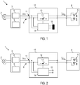
- Figure 1 shows a system 1 with a central unit 3, a DC bus 6, an operating device 6 and an LED module 8, which comprises several light emitting diodes (LEDs) 9.
- the LEDs 9 can be inorganic LEDs or organic LEDs.
- Figure 2 shows the same system 1 if the emergency light function is configured differently than in Figure 1 . Even if in Figure 1 and Figure 2 schematically only one operating device 10 and one LED module 8 assigned to it are shown, several operating devices can be connected to the DC bus 6 in order to generate an LED current for an LED module connected to their output.
- the central unit 3 comprises a supply circuit 4, which is set up to receive an AC voltage from an AC voltage source 2 in normal operation and to generate a DC supply voltage for the operating device 10.
- the supply circuit 4 can comprise an AC / DC converter.
- the supply circuit 4 can comprise electrical isolation in order to provide a voltage in the SELV ("Separated Extra Low Voltage") range on the DC bus 6 and to galvanically separate the DC bus 6 from an input side of the supply circuit 4.
- the system 1 comprises an energy store 5.
- the energy store 5 can serve as a voltage source in an emergency light case. As an emergency lighting case in particular considers the case in which the AC voltage source 2, for example the mains voltage, fails.
- the energy store 5 can be a battery or an accumulator.
- the energy store 5 can be a lead accumulator.
- the energy store 5 can be rechargeable.
- the energy store 5 can be set up in order to maintain a DC supply voltage on the DC bus 6 in an emergency lighting situation in order to supply some or all of the operating devices connected to the DC bus 6 with energy.
- the operating device 10 is set up to provide an LED current I LED for the LED module 8.
- the operating device 10 can comprise a DC / DC converter 12 in order to regulate the LED current to a desired value or to adjust it in some other way.
- the DC / DC converter can be a clocked converter, with a controllable switch 13 being switched clocked in order to generate the LED current for the LED module 8.
- the operating device 10 can have an emergency light function that is configurable. Due to the emergency light function, the operating device 10 can also generate the LED current for the LED module 8 in an emergency light case, for example if the AC voltage source 2 fails, for at least a predetermined period of time. The current strength of the LED current can be reduced in the event of an emergency in comparison to normal operation, for example to a maximum of 10% of the maximum current strength in normal operation.
- the configurability of the emergency light function makes it possible to determine whether the operating device 10 should provide the LED current at its output in the event of an emergency light. The configurability makes it possible to determine whether the operating device 10 is used for a lamp which contributes to emergency lighting or for a lamp which is switched off in the event of an emergency lighting.
- the configurable emergency light function can be implemented in different ways.
- a semiconductor integrated circuit 14 is set up to depend on a circuit element of the operating device 10 to determine whether the operating device 10 should generate the LED current in the event of an emergency light.
- the circuit element can be a manually manipulable circuit element. For example, by setting or removing a switching bridge 16, it can be determined whether the operating device also generates the LED current in the event of an emergency light.
- Figure 1 shows a system 1 in which a jumper 16 is present.
- the integrated semiconductor circuit 14 can detect the presence of the jumper 16, for example by a voltage or resistance measurement.
- the jumper can be a short circuit plug.
- Figure 2 shows the system 1 when the switching bridge 16 is not set and a receptacle 15 remains free for the switching bridge.
- the integrated semiconductor circuit 14 can recognize the absence of the switching bridge 16, for example by a voltage or resistance measurement.
- the emergency light function of the operating device 10 can be configured such that an LED current is generated in the event of an emergency light.
- the integrated semiconductor circuit 14 can recognize that the operating device 10 should also generate the LED current in the event of an emergency light.
- the integrated semiconductor circuit can recognize that the operating device 10 should not generate any LED current and should be switched off in the event of an emergency light.
- a reverse coding can also be used, in which the presence of the plug-in bridge 16, which connects two conductor tracks, indicates that the operating device 10 should not generate any LED current in the event of an emergency and should be switched off. With this coding, the absence of the jumper 15 would indicate that the operating device 10 should generate an LED current in the event of an emergency light.
- the operating circuit 10 can include a resistor that can be set to at least two values. The resistance can be set in a user-defined manner, for example by pressing a DIP switch. The integrated semiconductor circuit 10 can read out the set resistance and determine whether the set resistance value indicates a configuration of the emergency light function in which the operating device 10 is to generate an LED current in the event of an emergency light.
- an adjustable capacitance or another manually manipulable circuit element can be provided, the at least two states of which encode whether or not the operating device 10 should generate an LED current in the event of an emergency light.
- the operating device 10 is designed such that the configuration of the emergency light function is persistent and is retained when normal operation and emergency light case alternate one or more times. However, the operating device 10 can allow the emergency lighting function to be reconfigured, for example by removing or inserting the jumper 15 again, operating a DIP switch, changing a resistance value of a resistor or a capacitance of a capacitor in a user-defined manner, or manually operating a switch of the operating device 10 becomes.
- the integrated semiconductor circuit 14 can control the operating device 10 such that an LED current is only selectively generated in the event of an emergency lighting if the emergency lighting function of the operating device 10 is configured such that the operating device 10 continues to output an LED current in the event of an emergency lighting should. If the emergency lighting function of the operating device 10 is configured such that the operating device 10 is to continue to output an LED current in the event of an emergency lighting, the integrated semiconductor circuit 14 can control the operating device 10 in such a way that an LED current is also provided in normal operation. An operating device 10, which provides the LED current for the LED module 8 in the event of an emergency, can also generate an LED current in normal operation.
- the operating mode of the operating device 10 and in particular of the DC / DC converter 12 can be different in normal operation and in the event of an emergency light.
- the integrated semiconductor circuit 14 can switch the controllable switch 13 of the DC / DC converter 12 in such a way that the LED current has a lower current intensity in emergency lighting operation than in normal operation. If the operating device 10 is set up to enable dimming, the integrated semiconductor circuit 14 can switch the controllable switch 13 of the DC / DC converter 12 in such a way that in emergency lighting operation the LED current has a smaller current than the current at 100% dimming level , ie the maximum current, in normal operation.
- the operating device 10 can also be set up to work with different DC input voltages during normal operation and emergency lighting.
- the DC supply voltage on DC bus 3 can be greater in normal operation than in the event of an emergency light.
- the integrated semiconductor circuit 14 can change the clocked switching of the controllable switch 13, depending on whether the operating device 10 is currently operating in normal operation or in emergency lighting operation, in such a way that the differences between the operating modes exist in the current strength of the LED current and / or in the input voltages be taken into account.
- the operating device 10 can perform further functions. If the operating device 10 is set up for dimming, the integrated semiconductor circuit 14 can, for example, read out a dimming command and adapt a current control to the dimming level newly set by the dimming command.
- the dimming command can be transmitted via the DC bus 6 as a so-called PLC ("Power Line Communication").
- the operating device 10 can have a PLC demodulator for demodulating AC signals modulated onto the DC supply voltage, with which dimming commands are coded.
- the operating device 10 can also be set up for the transmission of information via the DC bus 6.
- the information can be, for example, information relevant to diagnosis be, for example, information about irregular operating conditions such as fault shutdowns.
- the information can be transmitted via the DC bus 6.
- Operating device 10 may include a PLC modulator for modulating AC signals onto DC bus 6 in order to transmit the information.
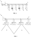
- FIG. 3 shows a system 1 with a plurality of lights 21-26, each of which is connected to the DC bus 6.
- Each of the lights 21-26 has an operating device 10 according to one embodiment and at least one light-emitting diode.
- the emergency light function is configured such that the corresponding lamp 22, 24 emits light in the event of an emergency, since the operating device 10 supplies the LEDs with the LED current.
- the emergency light function is configured such that the corresponding light 22, 24 does not emit any light in the event of an emergency, since the operating device 10 does not supply the LEDs with the LED current.
- Figure 4 shows a schematic side view of the system 1 in an emergency.
- the lights 21-26 can be wall or ceiling lights for building lighting.
- the lights 21-26 can be installed in a building.
- a light pattern of an emergency lighting can be defined. It is possible, but not absolutely necessary, to use the different operating devices 21-24 at one To control the emergency lighting situation by means of control commands addressed to the various operating devices in such a way that the corresponding light pattern is generated. Due to the configurable emergency light function, a change in the voltage level or a signal transmitted to all operating devices simultaneously via the DC bus 6 can indicate, for example, that the emergency light event occurs. In response to this, the operating devices 10 of the lights 22, 24 reduce the LED current for emergency lighting operation, while the operating devices 10 of a further part of the lights 23, 25 no longer generate any LED power and are switched off or go into a standby mode.
- an operating device can also be programmed via an interface.
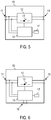
- FIG. 5 shows an operating device 10 according to a further embodiment.
- the operating device 10 is set up in such a way that the emergency light function can be configured via programming at the input 11, which is connected to the DC bus 6 when the operating device 10 is installed.
- the integrated semiconductor circuit 14 can monitor signals received at the input 11 with which the emergency light function can be configured.
- an AC voltage signal at input 10 with a first frequency can indicate that the emergency lighting function of operating device 10 is to be configured such that operating device 10 generates an LED current in the event of an emergency lighting.
- An AC voltage signal at the input 10 with a second frequency can indicate that the emergency light function of the operating device 10 is to be configured such that the operating device 10 does not generate any LED current in the event of an emergency light.
- Other programming is possible.
- a first binary sequence can be transmitted to the integrated semiconductor circuit, which indicates that the emergency lighting function of operating device 10 is to be configured such that operating device 10 generates an LED current in the event of an emergency lighting.
- a second binary sequence can be transmitted to the integrated semiconductor circuit, which indicates that the emergency lighting function of the operating device 10 should be configured such that the operating device 10 does not generate any LED current in the event of an emergency lighting.
- the operating device 10 can have a memory 17 in which it is stored whether or not the emergency light function is configured such that the operating device 10 generates an LED current in the event of an emergency light.
- the memory 17 can be a non-volatile memory.
- An interface other than the input 11 can also be used to program the operating device 10.
- Figure 6 shows an operating device 10 according to a further embodiment.
- the operating device 10 is set up in such a way that the emergency light function can be configured via programming at an interface 18.
- the interface 18 is different from the input 11, which is connected to the DC bus 6 in the installed state.
- the interface 18 can be a programming interface for the operating device, which is not used when the operating device 10 is installed.
- the interface 18 can also be a sensor interface to which a sensor can be connected when the operating device 10 is installed and which is temporarily used to configure the emergency light function in order to program the operating device 10. Programming can be done as with reference to Figure 5 described.
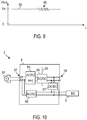
- Figure 7 10 is a flow diagram of a method 40 that is executed by an operating device 10 according to an embodiment.
- the operating device can supply 10 LEDs with an LED current in normal operation.
- the operating device 10 can determine whether there is an emergency light case. The detection of an emergency light case can be done, for example, by monitoring the voltage at the input coupled to the DC bus 6 11 done. If there is no emergency light case, the supply of the LEDs can be continued in step 41 in normal operation.
- the operating device 10 can determine in step 43 how the emergency lighting function of the operating device 10 is configured.
- the integrated semiconductor circuit 14 can query the state of a circuit element, for example the switching bridge 15, and / or read an indicator for the set configuration from a non-volatile memory 17.
- step 44 it is checked whether, according to the configuration of the emergency light function, the LED current should also be provided in the event of an emergency light. If the emergency light function is configured so that the LED current should also be provided in the event of an emergency light, the LEDs are supplied with an LED current for emergency light operation in step 45. A current strength of the LED current can be reduced compared to normal operation.
- step 44 If it is determined in step 44 that the emergency light function is configured such that the LED current should no longer be provided in the event of an emergency light, the generation of the LED current is ended in step 46.
- the control gear can go into a standby mode or be switched off.
- the operating device 10 can recognize the emergency light case in different ways, as can be seen from FIG Figure 8 and Figure 9 is described.
- Figure 8 shows a voltage on the DC bus 6 of a system according to an embodiment, when an emergency light event occurs.
- the DC supply voltage has a voltage level 56.
- the DC supply voltage on the DC bus 6 can drop to a further voltage level 58, which is lower than the voltage level 56.
- the integrated semiconductor circuit 14 of the operating device 14 can detect the falling voltage edge 57 and thereby determine that the emergency light is present.
- the system works in Emergency lighting operation. The end of the emergency lighting operation can be recognized by a rising voltage edge on the DC bus 6.
- the different voltage levels 56, 58 on the DC bus 6 in normal operation and in emergency lighting operation can result, for example, in that an output voltage of the energy store 5 is lower than the voltage level of the DC supply voltage generated by the central unit 3 in normal operation.
- a DC supply voltage of up to 60 volts e.g. a voltage of 48 volts are present on the DC bus 6.
- the DC supply voltage can be reduced to 24 volts or 12 volts, for example.
- the different voltage levels 56, 58 can be set by the central unit 3 in order to indicate the start and the end of the emergency lighting operation.
- Figure 9 shows a voltage on the DC bus 6 of a system according to an embodiment, when an emergency light event occurs.
- the central unit 3 can modulate an AC signal 56 onto the DC supply voltage 56 in order to indicate that the emergency light event occurs.
- the integrated semiconductor circuit 14 of the operating device 14 can recognize the AC signal 59 and thereby determine that the emergency light is present.
- the generation of the LED current can be ended or the LED current can be generated with a lower current intensity in order to supply the LEDs.
- the end of the emergency lighting operation can be indicated by a further AC signal on the DC bus 6.
- FIG 10 is a representation of the central unit 3 according to an embodiment.
- the central unit 3 comprises a supply circuit 4 with an input 62, which is coupled to an AC voltage source 61, for example the mains voltage.
- the supply circuit 4 can also be set up to be coupled to a photovoltaic element.
- the supply circuit 4 is set up to generate a DC supply voltage and to supply the operating device 10 with energy via the DC bus 6.
- the supply circuit 4 can comprise a rectifier and a power factor correction circuit 63.
- the supply circuit 4 can have a DC / DC converter with potential isolation in order to provide a potential barrier 65.
- the potential barrier 65 can be a SELV barrier.
- An energy store 5, which can be a rechargeable energy store, can be connected to the supply circuit 4 or integrated into it. It is also possible to provide the energy store separately from the supply circuit 4.
- the supply circuit 4 can be set up to charge the energy store 5 or to enable the energy store to be discharged via the DC bus 6 in the event of an emergency light.
- the supply circuit 4 can comprise an AC / DC converter 66 in order to generate a direct current for charging the energy store 5.
- the supply circuit 4 can comprise a DC / DC converter 67 which is operated in the event of an emergency to provide a DC supply voltage on the DC bus.
- the supply circuit 4 can provide a DC supply voltage at an output 68 both in normal operation and in the event of an emergency.
- the DC supply voltage can have different voltage levels in normal operation and in emergency lighting operation.
- an emergency lighting function of the operating device can also define more than two possible states. This would allow, in addition or as an alternative to a first configuration in which the operating device generates the LED current only in normal operation, and a second configuration in which the operating device generates the LED current both in normal operation and in the event of an emergency, further configurations define. For example, a third Configuration in which the control gear only generates the LED current in the event of an emergency lighting.
- the emergency light function can also be configured when the operating devices are installed.
- the emergency light function can be carried out via the DC bus in the PLC, the corresponding control signals containing address information for an operating device.
- Devices and methods according to exemplary embodiments can be used in particular for the operation of lamps which comprise LEDs.
Description
Die Erfindung betrifft einen Notlichtbetrieb von Leuchtmitteln. Die Erfindung betrifft insbesondere Betriebsgeräte, Leuchten, Systeme und Verfahren für einen Notlichtbetrieb, wenn ein Betriebsgerät für ein Leuchtmittel für eine Verbindung mit einem Gleichspannungs(DC)-Bus eingerichtet ist.The invention relates to emergency lighting of lamps. The invention relates in particular to operating devices, lights, systems and methods for emergency lighting operation when an operating device for a light source is set up for connection to a direct voltage (DC) bus.
Herkömmlich sind Betriebsgeräte für Leuchtdioden (LED) oder andere Leuchtmittel oft derart ausgestaltet, dass sie einen Eingang zur Kopplung mit einer Wechselspannungs(AC)-Versorgungsquelle aufweisen und an ihrem Ausgang einen Gleichstrom oder eine Gleichspannung für das Leuchtmittel bereitstellen. Betriebsgeräte, die eingerichtet ist, um eine DC-Versorgungsspannung zu empfangen, gewinnen in letzter Zeit zunehmend an Attraktivität. Zur Vereinfachung und Kosteneinsparung ist es dabei möglich, eine Zentraleinheit vorzusehen, die eine Gleichspannungs(DC)-Versorgungsspannung erzeugt und an ein Betriebsgerät oder mehrere Betriebsgeräte über einen DC-Bus bereitstellt. Die Betriebsgeräte sind separat von der Zentraleinheit vorgesehen und über den DC-Bus mit der Zentraleinheit verbunden.Conventionally, operating devices for light-emitting diodes (LED) or other light sources are often designed in such a way that they have an input for coupling to an AC voltage supply source and provide a direct current or a direct voltage for the light source at their output. Operating devices that are set up to receive a DC supply voltage have recently become increasingly attractive. To simplify and save costs, it is possible to provide a central unit that generates a direct voltage (DC) supply voltage and makes it available to one or more operating devices via a DC bus. The operating devices are provided separately from the central unit and connected to the central unit via the DC bus.
In zahlreichen Anwendungen, insbesondere für eine Gebäudebeleuchtung, ist der Einsatz einer Notbeleuchtung erforderlich oder wünschenswert. Die Notbeleuchtung kann als Fluchtwegbeleuchtung ausgestaltet sein, die in einem Notfall, insbesondere bei Ausfall eines Stromversorgungssystem, das Verlassen von Räumen ermöglichen soll. Die Notbeleuchtung kann die Funktion einer Anti-Panik-Beleuchtung erfüllen oder als eine Ersatzbeleuchtung wirken, die in einem Notfall die zeitweilige Fortsetzung von Arbeitsvorgängen erlaubt, um diese noch zu einem sicheren Abschluss zu bringen.In numerous applications, especially for building lighting, the use of emergency lighting is necessary or desirable. The emergency lighting can be configured as an escape route lighting, which is intended to enable people to leave rooms in the event of an emergency, in particular if a power supply system fails. The emergency lighting can fulfill the function of an anti-panic lighting or act as a replacement lighting, which in an emergency allows the temporary continuation of work processes in order to bring them to a safe conclusion.
Zur Bereitstellung einer Notbeleuchtung in Leuchtdioden(LED)-basierten Beleuchtungssystemen können spezifische LED-Module bereitgestellt werden, die sich von an den im Normalbetrieb verwendeten LED-Modulen unterscheiden und die im Notlichtfall aktiviert werden können. Dies kann Nachteile im Hinblick auf Kosten und Installationsraumerfordernisse mit sich bringen. Die
Es besteht ein Bedarf an Vorrichtungen, Systemen und Verfahren, mit denen in effizienter Weise ein Notlichtbetrieb bereitgestellt werden kann. Es besteht insbesondere Bedarf an Vorrichtungen, Systemen und Verfahren, mit denen bei einem Beleuchtungssystem mit einem DC-Bus zur Versorgung von Betriebsgeräten in einfacher Weise ein Notlichtbetrieb bereitgestellt werden kann.There is a need for devices, systems, and methods that can efficiently provide emergency lighting operation. There is a particular need for devices, systems and methods with which emergency lighting operation can be provided in a simple manner in a lighting system with a DC bus for supplying operating devices.
Aspekte der Erfindung sind in den unabhängigen Ansprüchen 1 und 15 dargestellt.Aspects of the invention are set out in
Nach Ausführungsbeispielen der Erfindung ist vorgesehen, dass ein Betriebsgerät für wenigstens eine Leuchtdiode eine konfigurierbare Notlichtfunktion aufweist. Die Konfigurierbarkeit kann derart sein, dass festgelegt werden kann, ob das entsprechende Betriebsgerät in einem Notlichtfall weiterhin einen LED-Strom für die ausgangsseitig angeschlossenen LEDs bereitstellen soll oder nicht. Das Betriebsgerät kann so ausgestaltet sein, dass auch in einem Notlichtfall das Betriebsgerät über einen DC-Bus mit einer DC-Versorgungsspannung versorgt wird. Dies erlaubt es, einen zentralen Energiespeicher für mehrere Leuchten zu verwenden, der im Notlichtfall die DC-Versorgungsspannung am DC-Bus bereitstellt. Die Kosten für eine Wartung dezentraler Energiespeicher für einen Notlichtbetrieb können so verringert werden.According to embodiments of the invention, it is provided that an operating device for at least one light-emitting diode has a configurable emergency light function. The configurability can be such that it can be determined whether or not the corresponding operating device should continue to provide an LED current for the LEDs connected on the output side in an emergency light case. The control gear can be designed such that the control gear is supplied with a DC supply voltage via a DC bus even in an emergency. This makes it possible to use a central energy store for several lights, which provides the DC supply voltage on the DC bus in the event of an emergency light. The costs for maintenance of decentralized energy stores for emergency lighting operation can thus be reduced.
Ein Betriebsgerät für wenigstens eine Leuchtdiode nach einem Ausführungsbeispiel ist für eine Kopplung mit einem DC-Bus zum Empfangen einer DC-Versorgungsspannung ausgestaltet. Das Betriebsgerät kann sowohl in einem Normalbetrieb als auch in einem Notlichtfall über den DC-Bus mit Energie versorgt werden. Das Betriebsgerät weist eine konfigurierbare Notlichtfunktion auf. Das Betriebsgerät ist eingerichtet, um in dem Notlichtfall den LED-Strom für die wenigstens eine Leuchtdiode abhängig davon zu erzeugen, wie die Notlichtfunktion konfiguriert ist.An operating device for at least one light-emitting diode according to one exemplary embodiment is designed for coupling to a DC bus for receiving a DC supply voltage. The control gear can be used in one Normal operation as well as in an emergency lighting situation can be supplied with energy via the DC bus. The control gear has a configurable emergency light function. The operating device is set up to generate the LED current for the at least one light-emitting diode in the event of an emergency depending on how the emergency light function is configured.
Ein derartiges Betriebsgerät kann in einem Notlichtfall über den DC-Bus von einem zentralen Energiespeicher mit Energie versorgt werden. Die Konfigurierbarkeit erlaubt eine Zuordnung, beispielsweise bei einer Installation des Betriebsgeräts oder der das Betriebsgerät enthaltenden Leuchte, ob das entsprechende Betriebsgerät auch im Notlichtfall für eine Lichtabgabe durch die wenigstens eine Leuchtdiode sorgen soll.In an emergency, such an operating device can be supplied with energy from a central energy store via the DC bus. The configurability allows an assignment, for example during installation of the operating device or the lamp containing the operating device, whether the corresponding operating device should also ensure that the at least one light-emitting diode emits light in the event of an emergency.
In einem System können an sich baugleiche Betriebsgeräte mit unterschiedlich konfigurierter Notlichtfunktion verwendet werden, um sowohl Leuchten, die nur im Normalbetrieb Licht abgeben, als auch Leuchten, die im Notlichtfall Licht abgeben, zu implementieren. Eine Festlegung der Funktionsweise im Notlichtfall und optional auch im Normalbetrieb kann durch die konfigurierbare Notlichtfunktion erreicht werden.In a system, identical control gear with a differently configured emergency light function can be used to implement both lights that only emit light in normal operation and lights that emit light in an emergency. The configurable emergency light function can be used to define the mode of operation in the event of an emergency light and optionally also in normal operation.
Durch die Konfigurierbarkeit der Notlichtfunktion kann selektiv nur einem Teil von mehreren Betriebsgeräten die Aufgabe zugewiesen werden, auch im Notlichtfall die zugeordneten Leuchtdioden mit dem LED-Strom zu versorgen. Dadurch kann der Energieverbrauch im Notlichtfall gesenkt werden und auch mit kleineren zentralen Energiespeichern die Notlichtfunktion für die aus Sicherheitsgründen erforderliche Zeitdauer aufrechterhalten werden.Due to the configurability of the emergency light function, the task of supplying the assigned light-emitting diodes with the LED current can be selectively assigned to only a part of several operating devices. As a result, the energy consumption in the event of an emergency light can be reduced and the emergency light function can be maintained for the period of time required for safety reasons even with smaller central energy stores.
Das Betriebsgerät kann so eingerichtet sein, dass die konfigurierte Notlichtfunktion beibehalten wird. Durch ein Umkonfigurieren kann eine Zuweisung, ob das entsprechende Betriebsgerät auch im Notlichtfall für eine Stromsversorgung der wenigstens einen Leuchtdiode sorgen soll, ermöglicht werden.The control gear can be set up so that the configured emergency lighting function is retained. By reconfiguring, an assignment can be made as to whether the corresponding operating device should also supply the at least one light-emitting diode in the event of an emergency.
Über die konfigurierbare Notlichtfunktion kann festlegbar sein, ob das Betriebsgerät den LED-Strom im Notlichtfall bereitstellt.The configurable emergency light function can be used to determine whether the control gear provides the LED current in the event of an emergency light.
Die Notlichtfunktion kann über wenigstens ein Schaltungselement des Betriebsgeräts konfigurierbar sein. Dies ermöglicht eine einfache Festlegung, beispielsweise durch manuelle Manipulation des Schaltungselements, ob das Betriebsgerät den LED-Strom im Notlichtfall erzeugt.The emergency light function can be configurable via at least one circuit element of the operating device. This enables simple determination, for example by manual manipulation of the circuit element, as to whether the operating device generates the LED current in the event of an emergency light.
Das wenigstens eine Schaltungselement kann eine Steckbrücke sein, die selektiv gesetzt oder entfernt werden kann, um festzulegen, ob das Betriebsgerät den LED-Strom im Notlichtfall bereitstellt oder nicht.The at least one circuit element can be a jumper that can be selectively set or removed in order to determine whether the operating device provides the LED current in the event of an emergency or not.
Das wenigstens eine Schaltungselement kann ein Widerstand sein, der durch eine Benutzeraktion auf wenigstens zwei unterschiedliche Werte eingestellt werden kann, um festzulegen, ob das Betriebsgerät den LED-Strom im Notlichtfall bereitstellt oder nicht.The at least one circuit element can be a resistor, which can be set to at least two different values by a user action in order to determine whether the operating device provides the LED current in the event of an emergency or not.
Das wenigstens eine Schaltungselement kann eine Kapazität sein, die durch eine Benutzeraktion auf wenigstens zwei unterschiedliche Werte eingestellt werden kann, um festzulegen, ob das Betriebsgerät den LED-Strom im Notlichtfall bereitstellt oder nicht.The at least one circuit element can be a capacitance which can be set to at least two different values by a user action in order to determine whether the operating device provides the LED current in the event of an emergency or not.
Das wenigstens eine Schaltungselement kann von einer integrierten Halbleiterschaltung ausgelesen werden, die das Betriebsgerät steuert. Die integrierte Halbleiterschaltung kann ein Mikrocontroller, ein Controller, ein Mikroprozessor, ein Prozessor oder eine anwendungsspezifische Spezialschaltung (ASIC) sein. Beispielsweise kenn die integrierte Halbleiterschaltung bestimmen, ob die Steckbrücke gesetzt ist oder auf welchen Wert der einstellbare Widerstand oder der einstellbare Kondensator eingestellt ist.The at least one circuit element can be read by an integrated semiconductor circuit that controls the operating device. The integrated semiconductor circuit can be a microcontroller, a controller, a microprocessor, a processor or an application-specific special circuit (ASIC). For example, the integrated semiconductor circuit can determine whether the jumper is set or to which value the adjustable resistor or the adjustable capacitor is set.
Die Notlichtfunktion kann auch durch eine Programmierung über eine Schnittstelle konfiguriert werden.The emergency light function can also be configured by programming via an interface.
Das Betriebsgerät kann eine Schnittstelle zum Empfangen eines Befehls aufweisen, mit dem die Notlichtfunktion konfiguriert wird. Als Schnittstelle, über die die Notlichtfunktion konfigurierbar ist, kann der Eingang dienen, mit dem das Betriebsgerät im installierten Zustand mit dem DC-Bus verbunden ist. Als Schnittstelle, über die die Notlichtfunktion konfigurierbar ist, kann eine nur zur Programmierung des Betriebsgeräts vorgesehene Schnittstelle dienen. Als Schnittstelle, über die die Notlichtfunktion konfigurierbar ist, kann eine Sensorschnittstelle verwendet werden, über die das Betriebsgerät im installierten Zustand mit einem Sensor, beispielsweise einem Temperatursensor, verbunden werden kann.The operating device can have an interface for receiving a command with which the emergency light function is configured. The input with which the control gear is connected to the DC bus in the installed state can serve as an interface via which the emergency light function can be configured. An interface provided only for programming the control gear can serve as the interface via which the emergency light function can be configured. A sensor interface can be used as the interface via which the emergency light function can be configured, via which the operating device can be connected to a sensor, for example a temperature sensor, in the installed state.
Das Betriebsgerät kann eine integrierte Halbleiterschaltung umfassen, die eingerichtet ist, um den Notlichtfall zu erkennen und um das Betriebsgerät in dem Notlichtfall abhängig davon zu steuern, wie die Notlichtfunktion konfiguriert ist.The operating device can comprise an integrated semiconductor circuit that is set up to recognize the emergency light case and to control the operating device in the emergency light case depending on how the emergency light function is configured.
Die integrierte Halbleiterschaltung kann mit dem Eingang verbunden sein und kann eingerichtet sein, um den Notlichtfall durch Überwachen einer Spannung an dem Eingang zu erkennen.The integrated semiconductor circuit can be connected to the input and can be set up to recognize the emergency light case by monitoring a voltage at the input.
Das Betriebsgerät kann einen DC/DC-Wandler mit einem steuerbaren Schalter umfassen. Die integrierte Halbleiterschaltung kann eingerichtet sein, um den steuerbaren Schalter in dem Notlichtfall getaktet zu schalten, um den LED-Strom bereitzustellen, wenn die Notlichtfunktion so konfiguriert ist, dass das Betriebsgerät den LED-Strom im Notlichtfall bereitstellt.The operating device can comprise a DC / DC converter with a controllable switch. The integrated semiconductor circuit can be set up to switch the controllable switch clocked in the emergency light case in order to provide the LED current if the emergency light function is configured such that the operating device provides the LED current in the event of an emergency light.
Das Betriebsgerät kann im Notlichtfall einen LED-Strom mit kleinerer Stromstärke erzeugen als im Normalbetrieb. Die integrierte Halbleiterschaltung kann eingerichtet sein, um den steuerbaren Schalter in dem Notlichtfall getaktet so zu schalten, dass der LED-Strom im Vergleich zum Normalbetrieb verringert wird.In the event of an emergency, the control gear can generate an LED current with a lower current than in normal operation. The integrated semiconductor circuit can be set up to switch the controllable switch in a clocked manner in the emergency light case in such a way that the LED current is reduced in comparison to normal operation.
Wenn das Betriebsgerät konfiguriert ist, um im Notlichtbetrieb den LED-Strom bereitzustellen, kann die integrierte Halbleiterschaltung das Betriebsgerät so steuern, dass sowohl im Normalbetrieb als auch im Notlichtbetrieb der LED-Strom für die wenigstens eine Leuchtdiode erzeugt wird.If the operating device is configured to provide the LED current in emergency lighting operation, the integrated semiconductor circuit can do the operating device in this way control that the LED current for the at least one light-emitting diode is generated both in normal operation and in emergency operation.
Eine Leuchte nach einem Ausführungsbeispiel umfasst ein Betriebsgerät nach einem Ausführungsbeispiel und wenigstens eine Leuchtdiode, die mit einem Ausgang des Betriebsgeräts verbunden ist.A lamp according to one embodiment comprises an operating device according to an embodiment and at least one light-emitting diode which is connected to an output of the operating device.
Die Leuchte kann als Leuchte für eine Gebäudebeleuchtung ausgestaltet sein. Die Leuchte kann eine Wand- oder Deckenleuchte sein.The luminaire can be designed as a luminaire for building lighting. The lamp can be a wall or ceiling lamp.
Ein Beleuchtungssystem nach einem Ausführungsbeispiel umfasst einen DC-Bus, wenigstens ein Betriebsgerät nach einem Ausführungsbeispiel, das mit dem DC-Bus verbunden ist, und eine DC-Spannungsquelle zum Bereitstellen der Versorgungsspannung an dem DC-Bus im Notlichtfall.A lighting system according to one exemplary embodiment comprises a DC bus, at least one operating device according to one exemplary embodiment which is connected to the DC bus, and a DC voltage source for providing the supply voltage on the DC bus in the event of an emergency.
Das Beleuchtungssystem kann mehrere Betriebsgeräte nach einem Ausführungsbeispiel umfassen. Die Notlichtfunktionen der mehreren Betriebsgeräte können so konfiguriert sein, dass nur bei einem Teil der mit dem DC-Bus verbundenen Betriebsgeräte festgelegt ist, dass die entsprechenden Betriebsgeräte in dem Notlichtfall den LED-Strom erzeugen. Dadurch kann der Energieverbrauch im Notlichtfall verringert werden, und die Dauer, über die die Notlichtbeleuchtung aufrecht erhalten werden kann, kann verlängert werden..The lighting system can comprise several operating devices according to one exemplary embodiment. The emergency lighting functions of the several operating devices can be configured in such a way that only a part of the operating devices connected to the DC bus is stipulated that the corresponding operating devices generate the LED current in the event of an emergency lighting. This can reduce the energy consumption in the event of an emergency lighting and the duration over which the emergency lighting can be maintained can be extended.
Die DC-Spannungsquelle für den Notlichtfall kann eine Batterie oder einen Ackumulator umfassen.The DC voltage source for the emergency lighting case can comprise a battery or an accumulator.
Das Beleuchtungssystem kann eine Zentraleinheit umfassen, die eine Versorgungsschaltung zum Bereitstellen der DC-Versorgungsspannung im Normalbetrieb umfasst. Die Versorgungsschaltung kann wenigstens einen AC/DC-Wandler, eine Leistungsfaktorkorrekturschaltung und eine galvanische Trennung umfassen. Der Akkumulator kann mit der Versorgungsschaltung verbunden sein. Im Normalbetrieb kann der Akkumulator aufgeladen werden, falls er nicht vollständig aufgeladen ist. Im Notlichtfall kann der Akkumulator selektiv mit dem DC-Bus verbunden werden, um die DC-Versorgungsspannung an dem DC-Bus bereitzustellen. Ein getakteter DC/DC-Wandler kann zwischen den Akkumulator und den DC-Bus geschaltet sein, um die DC-Versorgungsspannung im Notlichtfall auf einen gewünschten Spannungswert einzustellen.The lighting system can comprise a central unit, which comprises a supply circuit for providing the DC supply voltage in normal operation. The supply circuit can comprise at least one AC / DC converter, a power factor correction circuit and electrical isolation. The accumulator can be connected to the supply circuit. In normal operation, the accumulator can be charged if it is not fully charged. In the event of an emergency, the accumulator can be selectively connected to the DC bus in order to provide the DC supply voltage on the DC bus. A clocked DC / DC converter can be connected between the accumulator and the DC bus in order to set the DC supply voltage to a desired voltage value in the event of an emergency.
Der Notlichtfall kann ein Ausfall einer AC-Spannungsquelle, beispielsweise ein Ausfall einer Netzspannung sein.The emergency lighting case can be a failure of an AC voltage source, for example a failure of a mains voltage.
Bei einem Verfahren für einen Notlichtbetrieb wenigstens einer Leuchtdiode nach einem Ausführungsbeispiel wird ein Betriebsgerät verwendet, das einen Eingang für eine Kopplung mit einem DC-Bus zum Empfangen einer DC-Versorgungsspannung aufweist. Das Betriebsgerät weist eine konfigurierbare Notlichtfunktion auf. Das Verfahren umfasst ein Erkennen eines Notlichtfalls. Das Betriebsgerät stellt selektiv abhängig davon, wie die Notlichtfunktion des Betriebsgeräts konfiguriert ist, einen LED-Strom an die wenigstens eine Leuchtdiode bereit. Das Betriebsgerät wird in dem Notlichtfall über den DC-Bus mit der DC-Versorgungsspannung versorgt.In a method for emergency lighting operation of at least one light-emitting diode according to one exemplary embodiment, an operating device is used which has an input for coupling to a DC bus for receiving a DC supply voltage. The control gear has a configurable emergency light function. The method includes recognizing an emergency light case. Depending on how the emergency lighting function of the operating device is configured, the operating device selectively provides an LED current to the at least one light-emitting diode. In the event of an emergency, the control gear is supplied with the DC supply voltage via the DC bus.
Das Betriebsgerät kann den Notlichtfall erkennen, indem beispielsweise ein Spannungspegel an dem DC-Bus überwacht wird. Es kann eine Veränderung des Spannungspegels im Notlichtfall gegenüber dem Normalbetrieb erkannt werden. Alternativ oder zusätzlich kann ein über den DC-Bus übertragenes und der DC-Versorgungsspannung aufmoduliertes AC-Signal von dem Betriebsgerät ausgelesen werden, das anzeigt, dass ein Notlichtfall eintritt.The control gear can recognize the emergency lighting situation by, for example, monitoring a voltage level on the DC bus. A change in the voltage level in the event of an emergency light compared to normal operation can be detected. Alternatively or additionally, an AC signal transmitted via the DC bus and modulated onto the DC supply voltage can be read out by the operating device, which indicates that an emergency light event occurs.
Merkmale des Verfahrens nach weiteren Ausführungsbeispielen und die damit jeweils erzielten Wirkungen entsprechen den unter Bezugnahme auf die Betriebsgeräte, Leuchten und Beleuchtungssystemen beschriebenen Ausgestaltungen.Features of the method according to further exemplary embodiments and the effects achieved in each case correspond to the configurations described with reference to the operating devices, lights and lighting systems.
Das Verfahren kann von dem Betriebsgerät, der Leuchte oder dem Beleuchtungssystem nach einem Ausführungsbeispiel ausgeführt werden.The method can be carried out by the operating device, the lamp or the lighting system according to one exemplary embodiment.
Vorrichtungen und Verfahren nach Ausführungsbeispielen können insbesondere für Beleuchtungssysteme verwendet werden, bei denen das Leuchtmittel eine Leuchtdiode (LED) oder mehrere LEDs umfasst und das Betriebsgerät über einen DC-Bus mit einer DC-Versorgungsspannung versorgt wird.Devices and methods according to exemplary embodiments can be used in particular for lighting systems in which the illuminant comprises a light-emitting diode (LED) or several LEDs and the operating device is supplied with a DC supply voltage via a DC bus.
Weitere Merkmale, Vorteile und Funktionen von Ausführungsbeispielen der Erfindung werden aus der nachfolgenden detaillierten Beschreibung anhand der beigefügten Zeichnungen ersichtlich, in denen gleiche oder ähnliche Bezugszeichen Einheiten mit gleicher oder ähnlicher Funktion bezeichnen.
-
Figur 1 zeigt ein Beleuchtungssystem mit einem Betriebsgerät nach einem Ausführungsbeispiel der Erfindung. -
Figur 2Figur 1 , wenn das Betriebsgerät eine anders konfigurierte Notlichtfunktion als inFigur 1 aufweist. -
Figur 3 -
Figur 4Beleuchtungssystems von Figur 3 in einem Notlichtfall. -
Figur 5 -
Figur 6 -
Figur 7 ist ein Flussdiagramm eines Verfahrens, das von einem Betriebsgerät nach einem Ausführungsbeispiel ausgeführt wird. -
Figur 8 -
Figur 9 -
Figur 10
-
Figure 1 shows a lighting system with an operating device according to an embodiment of the invention. -
Figure 2 shows the lighting system fromFigure 1 , if the control gear has a differently configured emergency lighting function than inFigure 1 having. -
Figure 3 shows a lighting system with multiple lights according to an embodiment. -
Figure 4 illustrates an operation of the lighting system of FIGFigure 3 in an emergency light case. -
Figure 5 is a schematic representation of an operating device according to a further embodiment. -
Figure 6 is a schematic representation of an operating device according to a further embodiment. -
Figure 7 is a flow diagram of a method performed by an operating device is executed according to an embodiment. -
Figure 8 illustrates the detection of an emergency light case by monitoring a bus voltage according to an embodiment. -
Figure 9 illustrates the detection of an emergency light case by monitoring a bus voltage according to a further exemplary embodiment. -
Figure 10 shows a central unit of a lighting system according to an embodiment.
Die Zentraleinheit 3 umfasst eine Versorgungsschaltung 4, die eingerichtet ist, um in einem Normalbetrieb eine AC-Spannung von einer AC-Spannungsquelle 2 zu empfangen und eine DC-Versorgungsspannung für das Betriebsgerät 10 zu erzeugen. Die Versorgungsschaltung 4 kann einen AC/DC-Wandler umfassen. Die Versorgungsschaltung 4 kann eine Potenzialtrennung umfassen, um an dem DC-Bus 6 eine Spannung im SELV ("Separated Extra Low Voltage")-Bereich bereitzustellen und den DC-Bus 6 galvanisch von einer Eingangsseite der Versorgungsschaltung 4 zu trennen.The
Das System 1 umfasst einen Energiespeicher 5. Der Energiespeicher 5 kann als Spannungsquelle in einem Notlichtfall dienen. Als Notlichtfall wird insbesondere der Fall betrachtet, in dem die AC-Spannungsquelle 2, beispielsweise die Netzspannung, ausfällt. Der Energiespeicher 5 kann eine Batterie oder ein Akkumulator sein. Der Energiespeicher 5 kann ein Bleiakkumulator sein. Der Energiespeicher 5 kann wieder aufladbar sein. Der Energiespeicher 5 kann eingerichtet sein, um in einem Notlichtfall eine DC-Versorgungsspannung an dem DC-Bus 6 aufrecht zu erhalten, um einige oder alle der mit dem DC-Bus 6 verbundenen Betriebsgeräte mit Energie zu versorgen.The system 1 comprises an
Das Betriebsgerät 10 nach einem Ausführungsbeispiel ist eingerichtet, um einen LED-Strom ILED für das LED-Modul 8 bereitzustellen. Das Betriebsgerät 10 kann einen DC/DC-Wandler 12 umfassen, um den LED-Strom auf einen Sollwert zu regeln oder anderweitig einzustellen. Der DC/DC-Wandler kann ein getakteter Wandler sein, wobei ein steuerbarer Schalter 13 getaktet geschaltet wird, um den LED-Strom für das LED-Modul 8 zu erzeugen.The operating
Das Betriebsgerät 10 kann eine Notlichtfunktion aufweisen, die konfigurierbar ist. Durch die Notlichtfunktion kann von dem Betriebsgerät 10 auch in einem Notlichtfall, beispielsweise bei Ausfall der AC-Spannungsquelle 2, zumindest für eine vorgegebene Zeitdauer der LED-Strom für das LED-Modul 8 erzeugt werden. Die Stromstärke des LED-Stroms kann im Notlichtfall im Vergleich zum Normalbetrieb verringert sein, beispielsweise auf maximal 10 % der maximalen Stromstärke im Normalbetrieb. Durch die Konfigurierbarkeit der Notlichtfunktion kann festgelegt werden, ob das Betriebsgerät 10 im Notlichtfall den LED-Strom an seinem Ausgang bereitstellen soll. Durch die Konfigurierbarkeit kann festgelegt werden, ob das Betriebsgerät 10 für eine Leuchte, die zu einer Notbeleuchtung beiträgt, oder zu einer Leuchte, die im Notlichtfall abgeschaltet wird, eingesetzt wird.The operating
Die konfigurierbare Notlichtfunktion kann auf unterschiedliche Weise realisiert werden. Bei Ausführungsbeispielen, wie sie in
Durch Einsetzen oder Entfernen der Steckbrücke 16 kann die Notlichtfunktion des Betriebsgeräts 10 so konfiguriert werden, dass in dem Notlichtfall ein LED-Strom erzeugt wird. Beispielsweise kann die integrierte Halbleiterschaltung 14 dann, wenn die Steckbrücke 16 eingesetzt ist, erkennen, dass das Betriebsgerät 10 auch im Notlichtfall den LED-Strom erzeugen soll. Die integrierte Halbleiterschaltung kann dann, wenn die Steckbrücke 16 nicht eingesetzt ist, erkennen, dass das Betriebsgerät 10 im Notlichtfall keinen LED-Strom erzeugen und abgeschaltet werden soll. Es kann auch eine umgekehrte Kodierung eingesetzt werden, bei der das Vorhandensein der Steckbrücke 16, die zwei Leiterbahnen verbindet, anzeigt, dass das Betriebsgerät 10 im Notlichtfall keinen LED-Strom erzeugen und abgeschaltet werden soll. Bei dieser Kodierung würde das Fehlen der Steckbrücke 15 anzeigen, dass das Betriebsgerät 10 im Notlichtfall einen LED-Strom erzeugen soll.By inserting or removing the
Zahlreiche andere Ausgestaltungen der Betriebsschaltung 10 können verwendet werden, um eine Festlegung zu ermöglichen, ob die Betriebsschaltung 10 im Notlichtfall einen LED-Strom erzeugen soll. Beispielsweise kann die Betriebsschaltung 10 einen Widerstand umfassen, der auf wenigstens zwei Werte eingestellt werden kann. Der Widerstand kann benutzerdefiniert eingestellt werden, beispielsweise durch Betätigen eines DIP-Schalters. Die integrierte Halbleiterschaltung 10 kann den eingestellten Widerstand auslesen und ermitteln, ob der eingestellte Widerstandswert eine Konfiguration der Notlichtfunktion angibt, bei der das Betriebsgerät 10 im Notlichtfall einen LED-Strom erzeugen soll. Alternativ oder zusätzlich kann eine einstellbare Kapazität oder ein anderes manuell manipulierbares Schaltungselement vorgesehen werden, dessen wenigstens zwei Zustände kodieren, ob as Betriebsgerät 10 im Notlichtfall einen LED-Strom erzeugen soll oder nicht.Numerous other configurations of the
Das Betriebsgerät 10 ist so ausgestaltet, dass die Konfiguration der Notlichtfunktion persistent ist und beibehalten wird, wenn sich Normalbetrieb und Notlichtfall einmal oder mehrfach abwechseln. Allerdings kann das Betriebsgerät 10 ein Umkonfigurieren der Notlichtfunktion erlauben, beispielsweise indem die Steckbrücke 15 wieder entfernt oder neu eingefügt wird, ein DIP-Schalter betätigt, ein Widerstandswert eines Widerstands oder eine Kapazität eines Kondensators benutzerdefiniert verändert wird, oder ein Schalter des Betriebsgeräts 10 manuell betätigt wird.The operating
Falls ein Notlichtfall eintritt kann die integrierte Halbleiterschaltung 14 das Betriebsgerät 10 so steuern, dass selektiv nur dann ein LED-Strom im Notlichtfall erzeugt wird, wenn die Notlichtfunktion des Betriebsgeräts 10 so konfiguriert ist, dass das Betriebsgerät 10 im Notlichtfall weiterhin einen LED-Strom ausgeben soll. Wenn die Notlichtfunktion des Betriebsgeräts 10 so konfiguriert ist, dass das Betriebsgerät 10 im Notlichtfall weiterhin einen LED-Strom ausgeben soll, kann die integrierte Halbleiterschaltung 14 das Betriebsgerät 10 so steuern, dass auch im Normalbetrieb ein LED-Strom bereitgestellt wird. Ein Betriebsgerät 10, das im Notlichtfall den LED-Strom für das LED-Modul 8 bereitstellt, kann auch im Normalbetrieb einen LED-Strom erzeugen.If an emergency lighting event occurs, the
Die Arbeitsweise des Betriebsgeräts 10 und insbesondere des DC/DC-Wandlers 12 kann im Normalbetrieb und im Notlichtfall unterschiedlich sein. Insbesondere kann die integrierte Halbleiterschaltung 14 den steuerbaren Schalter 13 des DC/DC-Wandlers 12 so schalten, dass im Notlichtbetrieb der LED-Strom eine kleinere Stromstärke aufweist als im Normalbetrieb. Falls das Betriebsgerät 10 eingerichtet ist, um ein Dimmen zu ermöglichen, kann die integrierte Halbleiterschaltung 14 den steuerbaren Schalter 13 des DC/DC-Wandlers 12 so schalten, dass im Notlichtbetrieb der LED-Strom eine kleinere Stromstärke aufweist als die Stromstärke bei 100 % Dimmlevel, d.h. die maximale Stromstärke, im Normalbetrieb.The operating mode of the operating
Das Betriebsgerät 10 kann auch eingerichtet sein, um im Normalbetrieb und Notlichtfall mit unterschiedlichen DC-Eingangsspannungen zu arbeiten. Beispielweise kann die DC-Versorgungsspannung am DC-Bus 3 im Normalbetrieb größer sein als im Notlichtfall.The operating
Die integrierte Halbleiterschaltung 14 kann das getaktete Schalten des steuerbaren Schalters 13 abhängig davon, ob das Betriebsgerät 10 gerade im Normalbetrieb oder im Notlichtbetrieb arbeitet, so verändern, dass die zwischen den Betriebsarten existierenden Unterschiede in der Stromstärke des LED-Stroms und/oder in den Eingangsspannungen berücksichtigt werden.The
Das Betriebsgerät 10 kann weitere Funktionen erfüllen. Wenn das Betriebsgerät 10 für ein Dimmen eingerichtet ist, kann die integrierte Halbleiterschaltung 14 beispielsweise einen Dimmbefehl auslesen und eine Stromregelung an den durch den Dimmbefehl neu eingestellten Dimmlevel anpassen. Der Dimmbefehl kann über den DC-Bus 6 als sogenannte PLC ("Power Line Communication") übertragen werden. Das Betriebsgerät 10 kann einen PLC-Demodulator zum Demodulieren von auf die DC-Versorgungsspannung aufmodulierten AC-Signalen aufweisen, mit denen Dimmbefehle kodiert werden. Das Betriebsgerät 10 kann auch für eine Übertragung von Informationen über den DC-Bus 6 eingerichtet sein. Die Informationen können beispielsweise diagnoserelevante Informationen sein, z.B. Informationen über irreguläre Betriebszustände wie Fehlerabschaltungen. Die Informationen können über den DC-Bus 6 übertragen werden. Das Betriebsgerät 10 kann einen PLC-Modulator zum Aufmodulieren von AC-Signalen auf den DC-Bus 6 umfassen, um die Informationen zu übertragen.The operating
Aufgrund der Konfiguration der Notlichtfunktion der Betriebsgeräte 10 der Leuchten 22, 24 stellen diese Betriebsgeräte 10 den LED-Strom für die LEDs im Notlichtfall bereit, so dass die LEDs Licht 31, 33 abgeben.Due to the configuration of the emergency light function of the operating
Aufgrund der der Konfiguration der Notlichtfunktion der Betriebsgeräte 10 der weiteren Leuchten 23, 25 stellen diese Betriebsgeräte 10 im Notlichtfall keinen LED-Strom für die LEDs bereit, so dass die LEDs der weiteren Leuchten 23, 25 im Notlichtfall kein Licht abgeben.Due to the configuration of the emergency light function of the operating
Durch das Konfigurieren der Notlichtfunktionen der Betriebsgeräte kann ein Lichtmuster einer Notbeleuchtung festgelegt werden. Es ist möglich, aber nicht unbedingt erforderlich, die unterschiedlichen Betriebsgeräte 21-24 bei einem Notlichtfall durch an die verschiedenen Betriebsgeräte adressierte Steuerbefehle so zu steuern, dass das entsprechende Lichtmuster erzeugt wird. Aufgrund der konfigurierbaren Notlichtfunktion kann beispielsweise eine Veränderung des Spannungspegels oder ein an alle Betriebsgeräte gleichzeitig über den DC-Bus 6 übertragenes Signal anzeigen, dass der Notlichtfall eintritt. Als Antwort darauf verringern die Betriebsgeräte 10 der Leuchten 22, 24 den LED-Strom für einen Notlichtbetrieb, während die Betriebsgeräte 10 eines weiteren Teils der Leuchten 23, 25 gar keinen LED-Strom mehr erzeugen und abgeschaltet werden oder in einen Standby-Modus übergehen.By configuring the emergency lighting functions of the operating devices, a light pattern of an emergency lighting can be defined. It is possible, but not absolutely necessary, to use the different operating devices 21-24 at one To control the emergency lighting situation by means of control commands addressed to the various operating devices in such a way that the corresponding light pattern is generated. Due to the configurable emergency light function, a change in the voltage level or a signal transmitted to all operating devices simultaneously via the
Zahlreiche weitere Abwandlungen von Betriebsgeräten, Leuchten und Systemen nach Ausführungsbeispielen können realisiert werden. Beispielsweise kann die Notlichtfunktion eines Betriebsgeräts auch über eine Schnittstelle programmiert werden.Numerous further modifications of operating devices, lights and systems based on exemplary embodiments can be implemented. For example, the emergency lighting function of an operating device can also be programmed via an interface.
Das Betriebsgerät 10 kann einen Speicher 17 aufweisen, in dem gespeichert wird, ob die Notlichtfunktion so konfiguriert ist, dass das Betriebsgerät 10 im Notlichtfall einen LED-Strom erzeugt oder nicht. Der Speicher 17 kann ein nichtflüchtiger Speicher sein.The operating
Es kann auch eine andere Schnittstelle als der Eingang 11 verwendet werden, um das Betriebsgerät 10 zu programmieren.An interface other than the
Bei Schritt 41 kann das Betriebsgerät 10 LEDs im Normalbetrieb mit einem LED-Strom versorgen. Bei Schritt 42 kann das Betriebsgerät 10 ermitteln, ob ein Notlichtfall vorliegt. Die Erkennung eines Notlichtfalls kann beispielsweise durch Überwachung der Spannung an dem mit dem DC-Bus 6 gekoppelten Eingang 11 erfolgen. Falls kein Notlichtfall vorliegt, kann die Versorgung der LEDs im Normalbetrieb bei Schritt 41 fortgesetzt werden.In
Falls ein Notlichtfall erkannt wird, kann das Betriebsgerät 10 bei Schritt 43 ermitteln, wie die Notlichtfunktion des Betriebsgeräts 10 konfiguriert ist. Dazu kann die integrierte Hableiterschaltung 14 den Zustand eines Schaltungselements, beispielsweise der Schaltbrücke 15, abfragen und/oder einen Indikator für die eingestellte Konfiguration aus einem nicht-flüchtigen Speicher 17 auslesen.If an emergency light case is detected, the operating
Bei Schritt 44 wird überprüft, ob gemäß der Konfiguration der Notlichtfunktion der LED-Strom auch im Notlichtfall bereitgestellt werden soll. Falls die Notlichtfunktion so konfiguriert ist, dass der LED-Strom auch im Notlichtfall bereitgestellt werden soll, werden bei Schritt 45 die LEDs mit einem LED-Strom für den Notlichtbetrieb versorgt. Eine Stromstärke des LED-Stroms kann im Vergleich zu dem Normalbetrieb reduziert werden.In
Falls bei Schritt 44 ermittelt wird, dass die Notlichtfunktion so konfiguriert ist, dass der LED-Strom im Notlichtfall nicht mehr bereitgestellt werden soll, wird bei Schritt 46 die Erzeugung des LED-Stroms beendet. Das Betriebsgerät kann in einen Standby-Modus übergehen oder abgeschaltet werden.If it is determined in
Das Betriebsgerät 10 kann auf unterschiedliche Weise den Notlichtfall erkennen, wie anhand von
Die unterschiedlichen Spannungspegel 56, 58 am DC-Bus 6 im Normalbetrieb und im Notlichtbetrieb können beispielsweise dadurch resultieren, dass eine Ausgangsspannung des Energiespeichers 5 kleiner als der Spannungspegel der im Normalbetrieb von der Zentraleinheit 3 erzeugten DC-Versorgungsspannung ist. Beispielweise kann im Normalbetrieb eine DC-Versorgungsspannung von bis zu 60 Volt, z.B. eine Spannung von 48 Volt, an dem DC-Bus 6 anliegen. Im Notlichtbetrieb kann die DC-Versorgungsspannung beispielsweise auf 24 Volt oder 12 Volt gesenkt werden.The
Die unterschiedlichen Spannungspegel 56, 58 können von der Zentraleinheit 3 eingestellt werden, um den Beginn und das Ende des Notlichtbetriebs anzuzeigen.The
Die Versorgungsschaltung 4 ist eingerichtet, um eine DC-Versorgungsspannung zu erzeugen und um das Betriebsgerät 10 über den DC-Bus 6 mit Energie zu versorgen. Die Versorgungsschaltung 4 kann einen Gleichrichter und eine Leistungsfaktorkorrekturschaltung 63 umfassen. Die Versorgungsschaltung 4 kann einen DC/DC-Wandler mit Potenzialtrennung aufweisen, um eine Potenzialbarriere 65 bereitzustellen. Die Potenzialbarriere 65 kann eine SELV-Barriere sein.The
Ein Energiespeicher 5, der ein wieder aufladbarer Energiespeicher sein kann, kann mit der Versorgungsschaltung 4 verbunden oder in diese integriert sein. Es ist auch möglich, den Energiespeicher separat von der Versorgungsschaltung 4 vorzusehen.An
Die Versorgungsschaltung 4 kann eingerichtet sein, um den Energiespeicher 5 zu laden oder um ein Entladen des Energiespeichers über den DC-Bus 6 im Notlichtfall zu ermöglichen. Die Versorgungsschaltung 4 kann einen AC/DC-Wandler 66 umfassen, um einen Gleichstrom zum Laden des Energiespeichers 5 zu erzeugen. Die Versorgungsschaltung 4 kann einen DC/DC-Wandler 67 umfassen, der im Notlichtfall betrieben wird, um eine DC-Versorgungsspannung an dem DC-Bus bereitzustellen. Wie in
Während Ausführungsbeispiele unter Bezugnahme auf die Figuren beschrieben wurden, können Abwandlungen bei weiteren Ausführungsbeispielen verwendet werden. Beispielsweise kann eine Notlichtfunktion des Betriebsgeräts auch mehr als zwei mögliche Zustände definieren. Dies würde es erlauben, zusätzlich oder alternativ zu einer ersten Konfiguration, bei der das Betriebsgerät nur im Normalbetrieb den LED-Strom erzeugt, und einer zweiten Konfiguration, bei der das Betriebsgerät sowohl im Normalbetrieb als auch im Notlichtfall den LED-Strom erzeugt, weitere Konfigurationen zu definieren. Beispielsweise kann eine dritte Konfiguration festgelegt werden, bei der das Betriebsgerät nur im Notlichtfall den LED-Strom erzeugt.While exemplary embodiments have been described with reference to the figures, modifications can be used in further exemplary embodiments. For example, an emergency lighting function of the operating device can also define more than two possible states. This would allow, in addition or as an alternative to a first configuration in which the operating device generates the LED current only in normal operation, and a second configuration in which the operating device generates the LED current both in normal operation and in the event of an emergency, further configurations define. For example, a third Configuration in which the control gear only generates the LED current in the event of an emergency lighting.
Zusätzlich oder alternativ zu einer Programmierung der Betriebsgeräte über eine Schnittstelle bei der Installation der Betriebsgeräte kann die Notlichtfunktion auch im eingebauten Zustand der Betriebsgeräte konfiguriert werden. Die Notlichtfunktion kann über den DC-Bus in PLC erfolgen, wobei die entsprechenden Steuersignale Adressinformation für ein Betriebsgerät enthalten.In addition or as an alternative to programming the operating devices via an interface when installing the operating devices, the emergency light function can also be configured when the operating devices are installed. The emergency light function can be carried out via the DC bus in the PLC, the corresponding control signals containing address information for an operating device.
Vorrichtungen und Verfahren nach Ausführungsbeispielen können insbesondere für den Betrieb von Leuchtmitteln, die LEDs umfassen, eingesetzt werden.Devices and methods according to exemplary embodiments can be used in particular for the operation of lamps which comprise LEDs.
Claims (15)
- A lighting system (1), comprising:a central unit (3),a DC bus (6),at least one operating device (10) for at least one light-emitting diode (9),wherein the operating device (10) is connected via the DC bus (6) to the central unit (3),wherein the operating device (10) has an input (11) for a coupling with the DC bus (6) for receiving a DC supply voltage, via which the operating device (10) can be supplied with energy both in a normal operation as well as in an emergency light case via the DC bus,wherein the operating device (10) has a configurable emergency light function,wherein the operating device (10) is configured, in order to generate the LED current in the emergency light case for the at least one light-emitting diode (9) depending on how the emergency light function is configured,wherein the central unit (3) has a supply circuit (4) coupled with a photovoltaic element, which supply circuit is configured, in order to receive an AC voltage in the normal operation from an AC voltage source (2, 61) and to generate the DC supply voltage for the operating device (10), and has a DC voltage source (5) for providing the DC supply voltage in the emergency light case, characterized in thatthe central unit (3) and the operating device (10) are designed for PLC communication via the DC bus.
- The lighting system according to Claim 1,
wherein the central unit (3) and the operating device (10) are configured in such a manner that the central unit (3) configures the emergency light function of the operating device (10) by means of the PLC communication. - The lighting system according to Claim 1 or Claim 2,
wherein the operating device (10) has a PLC demodulator for demodulating AC signals of the central unit (3) modulated onto the DC supply voltage. - The lighting system according to Claim 3,
wherein the PLC demodulator is designed for demodulating AC signals of the central unit (3) modulated onto the DC supply voltage, with which dimming commands of the central unit (3) are coded. - The lighting system according to any one of the preceding claims,
wherein the operating device (10) has a PLC modulator for modulating AC signals onto the DC bus (6). - The lighting system according to any one of the preceding claims,
wherein it can be determined via the configurable emergency light function, whether the operating device (10) generates the LED current in the emergency light case. - The lighting system according to any one of the preceding claims,
wherein the operating device (10) has an interface (11; 18) for receiving a command for configuring the emergency light function. - The lighting system according to any one of the preceding claims,
wherein the operating device (10) has an integrated semi-conductor circuit (14), which is configured, in order to detect the emergency light case and in order to control the operating device (10) in the emergency light case depending on how the emergency light function is configured. - The lighting system according to Claim 8,
wherein the integrated semi-conductor circuit (14) is connected to the input of the operating device (10) and is configured, in order to detect the emergency light case by monitoring a voltage at the input (11). - The lighting system according to Claim 8 or Claim 9,
wherein the operating device (10) comprises a converter (12) with a controllable switch (13), and
wherein the integrated semi-conductor circuit (14) of the operating device (10) is configured, in order to switch the controllable switch (13) in the emergency light case in a clocked manner, in order to generate the LED current, if the emergency light function is configured so that the operating device (10) provides the LED current in the emergency light case. - The lighting system according to any one of the preceding claims,
wherein the DC voltage source (5) of the central unit (3) comprises a battery or an accumulator. - A lighting device (10) for a lighting system (1) according to any one of the preceding claims,
wherein the operating device (10) is designed for PLC communication with the central unit (3) of the lighting system (1). - A central unit (3) for a lighting system (1) according to any one of Claims 1-11,
wherein the central unit (3) has a supply circuit (4) coupled with a photovoltaic element, which supply circuit is configured, in order to receive an AC voltage in the normal operation from an AC voltage source (2, 61) and to generate the DC supply voltage for the operating device (10) of the lighting system (1), and a DC voltage source (5) for providing the DC supply voltage in the emergency light case, and
wherein the central unit (3) is designed for PLC communication with the operating device (10) of the lighting system (1) via the DC bus (6) of the lighting system (1). - The operating device (10) according to Claim 12 or the central unit (3) according to Claim 13,
wherein the operating device (10) or the central unit (3) is designed for use in the lighting system (1) according to any one Claims 1-11. - A method for an emergency light operation at least of one light-emitting diode (9) with a lighting system (1),
wherein the lighting system (1) comprises a central unit (3), a DC bus (6) and at least one operating device (10) for the at least one light-emitting diode (9) and the operating device (10) is connected via the DC bus (6) with the central unit (3),
wherein the operating device (10) has an input (11) for a coupling with the DC bus (6) for receiving a DC supply voltage and wherein the operating device (10) has a configurable emergency light function,
wherein the method comprises the steps:Detection of an emergency light case by the operating device (10), andprovision of an LED current by the operating device (10) to the at least one light-emitting diode (9) in the emergency light case depending on how the emergency light function of the operating device (10) is configured, wherein the operating device (10) is supplied in the emergency light case via the DC bus (6) with the DC supply voltage, wherein the central unit (3) has a supply circuit (4) coupled with a photovoltaic element and a DC voltage source (5), and wherein in the normal operation of the supply circuit (4) an AC voltage is received from an AC voltage source (2, 61) and the DC supply voltage for the operating device (10) is generated, while in the emergency light case the DC supply voltage is provided from the DC voltage source (5), characterized in that a PLC communication is carried out between the central unit (3) and the operating device (10) via the DC bus (6).
Applications Claiming Priority (4)
| Application Number | Priority Date | Filing Date | Title |
|---|---|---|---|
| ATGM137/2014U AT14562U1 (en) | 2014-03-26 | 2014-03-26 | Devices, systems and methods for emergency lighting operation |
| DE102014205646.2A DE102014205646A1 (en) | 2014-03-26 | 2014-03-26 | Devices, systems and methods for emergency lighting operation |
| PCT/AT2015/050071 WO2015143466A1 (en) | 2014-03-26 | 2015-03-18 | Devices, systems, and methods for emergency light operation |
| EP15715130.9A EP3123593B1 (en) | 2014-03-26 | 2015-03-18 | Devices, systems, and methods for emergency light operation |
Related Parent Applications (1)
| Application Number | Title | Priority Date | Filing Date |
|---|---|---|---|
| EP15715130.9A Division EP3123593B1 (en) | 2014-03-26 | 2015-03-18 | Devices, systems, and methods for emergency light operation |
Publications (2)
| Publication Number | Publication Date |
|---|---|
| EP3547493A1 EP3547493A1 (en) | 2019-10-02 |
| EP3547493B1 true EP3547493B1 (en) | 2020-05-20 |
Family
ID=52823401
Family Applications (2)
| Application Number | Title | Priority Date | Filing Date |
|---|---|---|---|
| EP15715130.9A Active EP3123593B1 (en) | 2014-03-26 | 2015-03-18 | Devices, systems, and methods for emergency light operation |
| EP19175646.9A Active EP3547493B1 (en) | 2014-03-26 | 2015-03-18 | Lighting system and method for operation of an emergency lighting |
Family Applications Before (1)
| Application Number | Title | Priority Date | Filing Date |
|---|---|---|---|
| EP15715130.9A Active EP3123593B1 (en) | 2014-03-26 | 2015-03-18 | Devices, systems, and methods for emergency light operation |
Country Status (4)
| Country | Link |
|---|---|
| US (1) | US10122206B2 (en) |
| EP (2) | EP3123593B1 (en) |
| CN (1) | CN106105397B (en) |
| WO (1) | WO2015143466A1 (en) |
Families Citing this family (4)
| Publication number | Priority date | Publication date | Assignee | Title |
|---|---|---|---|---|
| EP3076757B1 (en) * | 2015-03-30 | 2023-01-04 | OLEDWorks GmbH | Oled device and driving method |
| DE102016225495A1 (en) * | 2016-12-19 | 2018-06-21 | Tridonic Gmbh & Co. Kg | Lights bus system |
| US11152804B2 (en) | 2018-07-06 | 2021-10-19 | RR Solutions LLC | Circuit and method for detecting status of a DC power supply for charging a battery |
| TWM597022U (en) * | 2020-03-23 | 2020-06-11 | 柏友照明科技股份有限公司 | Led illumination device |
Family Cites Families (18)
| Publication number | Priority date | Publication date | Assignee | Title |
|---|---|---|---|---|
| US4150302A (en) * | 1977-04-25 | 1979-04-17 | Roche Thomas F | Emergency light battery charger circuit |
| DE2747173B2 (en) * | 1977-10-20 | 1979-11-15 | Praezisa Industrieelektronik Gmbh, 4300 Essen | Emergency light with luminous flux control |
| DE4134298A1 (en) | 1991-10-17 | 1993-04-22 | Abb Patent Gmbh | CONTROL AND MONITORING DEVICE FOR AN EMERGENCY LIGHT |
| DE29902892U1 (en) | 1999-02-18 | 2000-07-13 | Ceag Sicherheitstechnik Gmbh | Emergency lighting system |
| DE102004009993A1 (en) * | 2004-03-01 | 2005-09-22 | Tridonicatco Gmbh & Co. Kg | Electronic ballast with programmable or configurable control unit |
| US20060146553A1 (en) * | 2004-10-08 | 2006-07-06 | B/E Aerospace, Inc. | Dimmable reading light with emergency lighting capability |
| US7218056B1 (en) * | 2006-03-13 | 2007-05-15 | Ronald Paul Harwood | Lighting device with multiple power sources and multiple modes of operation |
| US20080024010A1 (en) * | 2006-07-31 | 2008-01-31 | John Romano | Automatic auxiliary lighting unit |
| US20080094857A1 (en) | 2006-10-20 | 2008-04-24 | Smith Robert B | LED light bulb |
| ITVI20070029A1 (en) * | 2007-01-31 | 2008-08-01 | Beghelli Spa | ELECTRONIC RECHARGE CONTROL SYSTEM FOR BATTERIES OF ACCUMULATORS, IN PARTICULAR FOR EMERGENCY LIGHTING LAMPS |
| IES20080132A2 (en) * | 2008-02-21 | 2009-03-18 | Atreus Entpr Ltd | Emergency light socket assembly |
| CN201718088U (en) * | 2010-05-25 | 2011-01-19 | 合肥三川自控工程有限责任公司 | Induction lighting lamp and induction lighting system |
| DE102011076714B4 (en) * | 2011-02-17 | 2024-01-04 | Tridonic Gmbh & Co Kg | Combined sensor/emergency light unit for a lighting system |
| JP5679197B2 (en) * | 2011-02-22 | 2015-03-04 | 野口 宏和 | Fluorescent lamp type LED lighting device |
| DE102011080996B4 (en) * | 2011-08-16 | 2024-02-15 | Tridonic Gmbh & Co Kg | Operation of a lamp with autonomous energy storage |
| CN102510609A (en) * | 2011-10-21 | 2012-06-20 | 宁顺卫 | System and method with common and emergency LED (light emitting diode) intelligent illumination |
| CN202310219U (en) * | 2011-10-28 | 2012-07-04 | 英属维京群岛商众上股份有限公司 | Multifunctional light emitting diode lighting lamp |
| US9871404B2 (en) | 2011-12-12 | 2018-01-16 | Cree, Inc. | Emergency lighting devices with LED strings |
-
2015
- 2015-03-18 CN CN201580015627.7A patent/CN106105397B/en active Active
- 2015-03-18 EP EP15715130.9A patent/EP3123593B1/en active Active
- 2015-03-18 WO PCT/AT2015/050071 patent/WO2015143466A1/en active Application Filing
- 2015-03-18 US US15/129,006 patent/US10122206B2/en active Active
- 2015-03-18 EP EP19175646.9A patent/EP3547493B1/en active Active
Non-Patent Citations (1)
| Title |
|---|
| None * |
Also Published As
| Publication number | Publication date |
|---|---|
| CN106105397B (en) | 2020-05-22 |
| EP3547493A1 (en) | 2019-10-02 |
| CN106105397A (en) | 2016-11-09 |
| US20170110905A1 (en) | 2017-04-20 |
| EP3123593A1 (en) | 2017-02-01 |
| US10122206B2 (en) | 2018-11-06 |
| EP3123593B1 (en) | 2019-05-22 |
| WO2015143466A1 (en) | 2015-10-01 |
Similar Documents
| Publication | Publication Date | Title |
|---|---|---|
| EP3547493B1 (en) | Lighting system and method for operation of an emergency lighting | |
| EP1555859A1 (en) | Control of lighting devices over a modulated DC bus | |
| DE102011100002B4 (en) | Device for controlling a lighting device | |
| EP3549233B1 (en) | Operating device having a test switch and status indicator | |
| EP2676531A1 (en) | Combined sensor/emergency light unit for a lighting system | |
| DE10103611B4 (en) | Circuit arrangement for operating a plurality of bulbs | |
| DE102014112726A1 (en) | Device for controlling and powering lights and / or bulbs of emergency lighting | |
| DE102016201390A1 (en) | Supply unit for a bus | |
| EP2929756B1 (en) | Operating device for illuminant and related method | |
| DE102014205646A1 (en) | Devices, systems and methods for emergency lighting operation | |
| DE102010040398A1 (en) | Improvement of the energy efficiency of at least one light source having lighting system and corresponding lighting system | |
| AT16798U1 (en) | Sensor for lighting control with constant current converters | |
| EP3351056B1 (en) | Supply unit for a bus | |
| DE102017110798A1 (en) | Emission control device, light emission module, light emission unit and lighting fixture | |
| DE112011102274B4 (en) | Control of operating parameters of control gear for LED | |
| DE112011100717B4 (en) | Operating device for lamps and bus system and method for operating a control gear | |
| EP2425683B1 (en) | Interface for a lighting system | |
| AT14562U1 (en) | Devices, systems and methods for emergency lighting operation | |
| WO2015143465A1 (en) | Operating circuit, control gear, lighting system and method for operating at least one light-emitting diode | |
| EP3127401A1 (en) | Operating device, luminaire, and method for operating an illumination means | |
| EP3058795A1 (en) | Method and device for communication in a lighting system | |
| EP2362718A2 (en) | Module and method for controlling a dimmable operating device | |
| DE102014205665B4 (en) | Operating circuit, operating device, lighting system and method for operating at least one light-emitting diode | |
| DE102009051738A1 (en) | Emergency lighting device with LED | |
| DE102015217835A1 (en) | Supply unit for a bus |
Legal Events
| Date | Code | Title | Description |
|---|---|---|---|
| PUAI | Public reference made under article 153(3) epc to a published international application that has entered the european phase |
Free format text: ORIGINAL CODE: 0009012 |
|
| STAA | Information on the status of an ep patent application or granted ep patent |
Free format text: STATUS: THE APPLICATION HAS BEEN PUBLISHED |
|
| AC | Divisional application: reference to earlier application |
Ref document number: 3123593 Country of ref document: EP Kind code of ref document: P |
|
| AK | Designated contracting states |
Kind code of ref document: A1 Designated state(s): AL AT BE BG CH CY CZ DE DK EE ES FI FR GB GR HR HU IE IS IT LI LT LU LV MC MK MT NL NO PL PT RO RS SE SI SK SM TR |
|
| STAA | Information on the status of an ep patent application or granted ep patent |
Free format text: STATUS: REQUEST FOR EXAMINATION WAS MADE |
|
| 17P | Request for examination filed |
Effective date: 20191127 |
|
| RBV | Designated contracting states (corrected) |
Designated state(s): AL AT BE BG CH CY CZ DE DK EE ES FI FR GB GR HR HU IE IS IT LI LT LU LV MC MK MT NL NO PL PT RO RS SE SI SK SM TR |
|
| REG | Reference to a national code |
Ref country code: DE Ref legal event code: R079 Ref document number: 502015012636 Country of ref document: DE Free format text: PREVIOUS MAIN CLASS: H02J0009020000 Ipc: H02J0009000000 |
|
| GRAP | Despatch of communication of intention to grant a patent |
Free format text: ORIGINAL CODE: EPIDOSNIGR1 |
|
| STAA | Information on the status of an ep patent application or granted ep patent |
Free format text: STATUS: GRANT OF PATENT IS INTENDED |
|
| RIC1 | Information provided on ipc code assigned before grant |
Ipc: H02J 9/00 20060101AFI20200107BHEP Ipc: H05B 47/105 20200101ALI20200107BHEP Ipc: H02J 9/06 20060101ALI20200107BHEP Ipc: H05B 45/00 20200101ALI20200107BHEP |
|
| INTG | Intention to grant announced |
Effective date: 20200206 |
|
| GRAS | Grant fee paid |
Free format text: ORIGINAL CODE: EPIDOSNIGR3 |
|
| GRAA | (expected) grant |
Free format text: ORIGINAL CODE: 0009210 |
|
| STAA | Information on the status of an ep patent application or granted ep patent |
Free format text: STATUS: THE PATENT HAS BEEN GRANTED |
|
| AC | Divisional application: reference to earlier application |
Ref document number: 3123593 Country of ref document: EP Kind code of ref document: P |
|
| AK | Designated contracting states |
Kind code of ref document: B1 Designated state(s): AL AT BE BG CH CY CZ DE DK EE ES FI FR GB GR HR HU IE IS IT LI LT LU LV MC MK MT NL NO PL PT RO RS SE SI SK SM TR |
|
| REG | Reference to a national code |
Ref country code: GB Ref legal event code: FG4D Free format text: NOT ENGLISH |
|
| REG | Reference to a national code |
Ref country code: CH Ref legal event code: EP Ref country code: CH Ref legal event code: NV Representative=s name: VALIPAT S.A. C/O BOVARD SA NEUCHATEL, CH |
|
| REG | Reference to a national code |
Ref country code: DE Ref legal event code: R096 Ref document number: 502015012636 Country of ref document: DE |
|
| REG | Reference to a national code |
Ref country code: AT Ref legal event code: REF Ref document number: 1273257 Country of ref document: AT Kind code of ref document: T Effective date: 20200615 |
|
| REG | Reference to a national code |
Ref country code: LT Ref legal event code: MG4D |
|
| REG | Reference to a national code |
Ref country code: NL Ref legal event code: MP Effective date: 20200520 |
|
| PG25 | Lapsed in a contracting state [announced via postgrant information from national office to epo] |
Ref country code: PT Free format text: LAPSE BECAUSE OF FAILURE TO SUBMIT A TRANSLATION OF THE DESCRIPTION OR TO PAY THE FEE WITHIN THE PRESCRIBED TIME-LIMIT Effective date: 20200921 Ref country code: IS Free format text: LAPSE BECAUSE OF FAILURE TO SUBMIT A TRANSLATION OF THE DESCRIPTION OR TO PAY THE FEE WITHIN THE PRESCRIBED TIME-LIMIT Effective date: 20200920 Ref country code: FI Free format text: LAPSE BECAUSE OF FAILURE TO SUBMIT A TRANSLATION OF THE DESCRIPTION OR TO PAY THE FEE WITHIN THE PRESCRIBED TIME-LIMIT Effective date: 20200520 Ref country code: NO Free format text: LAPSE BECAUSE OF FAILURE TO SUBMIT A TRANSLATION OF THE DESCRIPTION OR TO PAY THE FEE WITHIN THE PRESCRIBED TIME-LIMIT Effective date: 20200820 Ref country code: GR Free format text: LAPSE BECAUSE OF FAILURE TO SUBMIT A TRANSLATION OF THE DESCRIPTION OR TO PAY THE FEE WITHIN THE PRESCRIBED TIME-LIMIT Effective date: 20200821 Ref country code: SE Free format text: LAPSE BECAUSE OF FAILURE TO SUBMIT A TRANSLATION OF THE DESCRIPTION OR TO PAY THE FEE WITHIN THE PRESCRIBED TIME-LIMIT Effective date: 20200520 Ref country code: LT Free format text: LAPSE BECAUSE OF FAILURE TO SUBMIT A TRANSLATION OF THE DESCRIPTION OR TO PAY THE FEE WITHIN THE PRESCRIBED TIME-LIMIT Effective date: 20200520 |
|
| PG25 | Lapsed in a contracting state [announced via postgrant information from national office to epo] |
Ref country code: BG Free format text: LAPSE BECAUSE OF FAILURE TO SUBMIT A TRANSLATION OF THE DESCRIPTION OR TO PAY THE FEE WITHIN THE PRESCRIBED TIME-LIMIT Effective date: 20200820 Ref country code: HR Free format text: LAPSE BECAUSE OF FAILURE TO SUBMIT A TRANSLATION OF THE DESCRIPTION OR TO PAY THE FEE WITHIN THE PRESCRIBED TIME-LIMIT Effective date: 20200520 Ref country code: LV Free format text: LAPSE BECAUSE OF FAILURE TO SUBMIT A TRANSLATION OF THE DESCRIPTION OR TO PAY THE FEE WITHIN THE PRESCRIBED TIME-LIMIT Effective date: 20200520 Ref country code: RS Free format text: LAPSE BECAUSE OF FAILURE TO SUBMIT A TRANSLATION OF THE DESCRIPTION OR TO PAY THE FEE WITHIN THE PRESCRIBED TIME-LIMIT Effective date: 20200520 |
|
| PG25 | Lapsed in a contracting state [announced via postgrant information from national office to epo] |
Ref country code: AL Free format text: LAPSE BECAUSE OF FAILURE TO SUBMIT A TRANSLATION OF THE DESCRIPTION OR TO PAY THE FEE WITHIN THE PRESCRIBED TIME-LIMIT Effective date: 20200520 Ref country code: NL Free format text: LAPSE BECAUSE OF FAILURE TO SUBMIT A TRANSLATION OF THE DESCRIPTION OR TO PAY THE FEE WITHIN THE PRESCRIBED TIME-LIMIT Effective date: 20200520 |
|
| PG25 | Lapsed in a contracting state [announced via postgrant information from national office to epo] |
Ref country code: DK Free format text: LAPSE BECAUSE OF FAILURE TO SUBMIT A TRANSLATION OF THE DESCRIPTION OR TO PAY THE FEE WITHIN THE PRESCRIBED TIME-LIMIT Effective date: 20200520 Ref country code: ES Free format text: LAPSE BECAUSE OF FAILURE TO SUBMIT A TRANSLATION OF THE DESCRIPTION OR TO PAY THE FEE WITHIN THE PRESCRIBED TIME-LIMIT Effective date: 20200520 Ref country code: IT Free format text: LAPSE BECAUSE OF FAILURE TO SUBMIT A TRANSLATION OF THE DESCRIPTION OR TO PAY THE FEE WITHIN THE PRESCRIBED TIME-LIMIT Effective date: 20200520 Ref country code: RO Free format text: LAPSE BECAUSE OF FAILURE TO SUBMIT A TRANSLATION OF THE DESCRIPTION OR TO PAY THE FEE WITHIN THE PRESCRIBED TIME-LIMIT Effective date: 20200520 Ref country code: CZ Free format text: LAPSE BECAUSE OF FAILURE TO SUBMIT A TRANSLATION OF THE DESCRIPTION OR TO PAY THE FEE WITHIN THE PRESCRIBED TIME-LIMIT Effective date: 20200520 Ref country code: SM Free format text: LAPSE BECAUSE OF FAILURE TO SUBMIT A TRANSLATION OF THE DESCRIPTION OR TO PAY THE FEE WITHIN THE PRESCRIBED TIME-LIMIT Effective date: 20200520 Ref country code: EE Free format text: LAPSE BECAUSE OF FAILURE TO SUBMIT A TRANSLATION OF THE DESCRIPTION OR TO PAY THE FEE WITHIN THE PRESCRIBED TIME-LIMIT Effective date: 20200520 |
|
| REG | Reference to a national code |
Ref country code: DE Ref legal event code: R084 Ref document number: 502015012636 Country of ref document: DE |
|
| REG | Reference to a national code |
Ref country code: DE Ref legal event code: R097 Ref document number: 502015012636 Country of ref document: DE |
|
| PG25 | Lapsed in a contracting state [announced via postgrant information from national office to epo] |
Ref country code: SK Free format text: LAPSE BECAUSE OF FAILURE TO SUBMIT A TRANSLATION OF THE DESCRIPTION OR TO PAY THE FEE WITHIN THE PRESCRIBED TIME-LIMIT Effective date: 20200520 Ref country code: PL Free format text: LAPSE BECAUSE OF FAILURE TO SUBMIT A TRANSLATION OF THE DESCRIPTION OR TO PAY THE FEE WITHIN THE PRESCRIBED TIME-LIMIT Effective date: 20200520 |
|
| PLBE | No opposition filed within time limit |
Free format text: ORIGINAL CODE: 0009261 |
|
| STAA | Information on the status of an ep patent application or granted ep patent |
Free format text: STATUS: NO OPPOSITION FILED WITHIN TIME LIMIT |
|
| 26N | No opposition filed |
Effective date: 20210223 |
|
| PGFP | Annual fee paid to national office [announced via postgrant information from national office to epo] |
Ref country code: AT Payment date: 20210319 Year of fee payment: 7 |
|
| PG25 | Lapsed in a contracting state [announced via postgrant information from national office to epo] |
Ref country code: MC Free format text: LAPSE BECAUSE OF FAILURE TO SUBMIT A TRANSLATION OF THE DESCRIPTION OR TO PAY THE FEE WITHIN THE PRESCRIBED TIME-LIMIT Effective date: 20200520 |
|
| REG | Reference to a national code |
Ref country code: BE Ref legal event code: MM Effective date: 20210331 |
|
| PG25 | Lapsed in a contracting state [announced via postgrant information from national office to epo] |
Ref country code: LU Free format text: LAPSE BECAUSE OF NON-PAYMENT OF DUE FEES Effective date: 20210318 Ref country code: IE Free format text: LAPSE BECAUSE OF NON-PAYMENT OF DUE FEES Effective date: 20210318 |
|
| PGFP | Annual fee paid to national office [announced via postgrant information from national office to epo] |
Ref country code: CH Payment date: 20220324 Year of fee payment: 8 |
|
| PG25 | Lapsed in a contracting state [announced via postgrant information from national office to epo] |
Ref country code: BE Free format text: LAPSE BECAUSE OF NON-PAYMENT OF DUE FEES Effective date: 20210331 |
|
| REG | Reference to a national code |
Ref country code: AT Ref legal event code: MM01 Ref document number: 1273257 Country of ref document: AT Kind code of ref document: T Effective date: 20220318 |
|
| PG25 | Lapsed in a contracting state [announced via postgrant information from national office to epo] |
Ref country code: AT Free format text: LAPSE BECAUSE OF NON-PAYMENT OF DUE FEES Effective date: 20220318 |
|
| PGFP | Annual fee paid to national office [announced via postgrant information from national office to epo] |
Ref country code: FR Payment date: 20230323 Year of fee payment: 9 |
|
| PGFP | Annual fee paid to national office [announced via postgrant information from national office to epo] |
Ref country code: GB Payment date: 20230321 Year of fee payment: 9 Ref country code: DE Payment date: 20230328 Year of fee payment: 9 |
|
| PG25 | Lapsed in a contracting state [announced via postgrant information from national office to epo] |
Ref country code: CY Free format text: LAPSE BECAUSE OF FAILURE TO SUBMIT A TRANSLATION OF THE DESCRIPTION OR TO PAY THE FEE WITHIN THE PRESCRIBED TIME-LIMIT Effective date: 20200520 |
|
| P01 | Opt-out of the competence of the unified patent court (upc) registered |
Effective date: 20230530 |
|
| PG25 | Lapsed in a contracting state [announced via postgrant information from national office to epo] |
Ref country code: HU Free format text: LAPSE BECAUSE OF FAILURE TO SUBMIT A TRANSLATION OF THE DESCRIPTION OR TO PAY THE FEE WITHIN THE PRESCRIBED TIME-LIMIT; INVALID AB INITIO Effective date: 20150318 |
|
| PG25 | Lapsed in a contracting state [announced via postgrant information from national office to epo] |
Ref country code: SI Free format text: LAPSE BECAUSE OF FAILURE TO SUBMIT A TRANSLATION OF THE DESCRIPTION OR TO PAY THE FEE WITHIN THE PRESCRIBED TIME-LIMIT Effective date: 20200520 |
|
| REG | Reference to a national code |
Ref country code: CH Ref legal event code: PL |
|
| PG25 | Lapsed in a contracting state [announced via postgrant information from national office to epo] |
Ref country code: LI Free format text: LAPSE BECAUSE OF NON-PAYMENT OF DUE FEES Effective date: 20230331 Ref country code: CH Free format text: LAPSE BECAUSE OF NON-PAYMENT OF DUE FEES Effective date: 20230331 |