EP3547489A2 - Method of battery charging and energy station - Google Patents
Method of battery charging and energy station Download PDFInfo
- Publication number
- EP3547489A2 EP3547489A2 EP19163076.3A EP19163076A EP3547489A2 EP 3547489 A2 EP3547489 A2 EP 3547489A2 EP 19163076 A EP19163076 A EP 19163076A EP 3547489 A2 EP3547489 A2 EP 3547489A2
- Authority
- EP
- European Patent Office
- Prior art keywords
- battery
- user end
- cloud server
- controller
- identifiers
- Prior art date
- Legal status (The legal status is an assumption and is not a legal conclusion. Google has not performed a legal analysis and makes no representation as to the accuracy of the status listed.)
- Withdrawn
Links
Images


Classifications
-
- B—PERFORMING OPERATIONS; TRANSPORTING
- B60—VEHICLES IN GENERAL
- B60L—PROPULSION OF ELECTRICALLY-PROPELLED VEHICLES; SUPPLYING ELECTRIC POWER FOR AUXILIARY EQUIPMENT OF ELECTRICALLY-PROPELLED VEHICLES; ELECTRODYNAMIC BRAKE SYSTEMS FOR VEHICLES IN GENERAL; MAGNETIC SUSPENSION OR LEVITATION FOR VEHICLES; MONITORING OPERATING VARIABLES OF ELECTRICALLY-PROPELLED VEHICLES; ELECTRIC SAFETY DEVICES FOR ELECTRICALLY-PROPELLED VEHICLES
- B60L53/00—Methods of charging batteries, specially adapted for electric vehicles; Charging stations or on-board charging equipment therefor; Exchange of energy storage elements in electric vehicles
- B60L53/60—Monitoring or controlling charging stations
- B60L53/66—Data transfer between charging stations and vehicles
-
- B—PERFORMING OPERATIONS; TRANSPORTING
- B60—VEHICLES IN GENERAL
- B60L—PROPULSION OF ELECTRICALLY-PROPELLED VEHICLES; SUPPLYING ELECTRIC POWER FOR AUXILIARY EQUIPMENT OF ELECTRICALLY-PROPELLED VEHICLES; ELECTRODYNAMIC BRAKE SYSTEMS FOR VEHICLES IN GENERAL; MAGNETIC SUSPENSION OR LEVITATION FOR VEHICLES; MONITORING OPERATING VARIABLES OF ELECTRICALLY-PROPELLED VEHICLES; ELECTRIC SAFETY DEVICES FOR ELECTRICALLY-PROPELLED VEHICLES
- B60L53/00—Methods of charging batteries, specially adapted for electric vehicles; Charging stations or on-board charging equipment therefor; Exchange of energy storage elements in electric vehicles
- B60L53/30—Constructional details of charging stations
- B60L53/31—Charging columns specially adapted for electric vehicles
-
- B—PERFORMING OPERATIONS; TRANSPORTING
- B60—VEHICLES IN GENERAL
- B60L—PROPULSION OF ELECTRICALLY-PROPELLED VEHICLES; SUPPLYING ELECTRIC POWER FOR AUXILIARY EQUIPMENT OF ELECTRICALLY-PROPELLED VEHICLES; ELECTRODYNAMIC BRAKE SYSTEMS FOR VEHICLES IN GENERAL; MAGNETIC SUSPENSION OR LEVITATION FOR VEHICLES; MONITORING OPERATING VARIABLES OF ELECTRICALLY-PROPELLED VEHICLES; ELECTRIC SAFETY DEVICES FOR ELECTRICALLY-PROPELLED VEHICLES
- B60L53/00—Methods of charging batteries, specially adapted for electric vehicles; Charging stations or on-board charging equipment therefor; Exchange of energy storage elements in electric vehicles
- B60L53/60—Monitoring or controlling charging stations
- B60L53/65—Monitoring or controlling charging stations involving identification of vehicles or their battery types
-
- B—PERFORMING OPERATIONS; TRANSPORTING
- B60—VEHICLES IN GENERAL
- B60L—PROPULSION OF ELECTRICALLY-PROPELLED VEHICLES; SUPPLYING ELECTRIC POWER FOR AUXILIARY EQUIPMENT OF ELECTRICALLY-PROPELLED VEHICLES; ELECTRODYNAMIC BRAKE SYSTEMS FOR VEHICLES IN GENERAL; MAGNETIC SUSPENSION OR LEVITATION FOR VEHICLES; MONITORING OPERATING VARIABLES OF ELECTRICALLY-PROPELLED VEHICLES; ELECTRIC SAFETY DEVICES FOR ELECTRICALLY-PROPELLED VEHICLES
- B60L53/00—Methods of charging batteries, specially adapted for electric vehicles; Charging stations or on-board charging equipment therefor; Exchange of energy storage elements in electric vehicles
- B60L53/60—Monitoring or controlling charging stations
- B60L53/66—Data transfer between charging stations and vehicles
- B60L53/665—Methods related to measuring, billing or payment
-
- B—PERFORMING OPERATIONS; TRANSPORTING
- B60—VEHICLES IN GENERAL
- B60L—PROPULSION OF ELECTRICALLY-PROPELLED VEHICLES; SUPPLYING ELECTRIC POWER FOR AUXILIARY EQUIPMENT OF ELECTRICALLY-PROPELLED VEHICLES; ELECTRODYNAMIC BRAKE SYSTEMS FOR VEHICLES IN GENERAL; MAGNETIC SUSPENSION OR LEVITATION FOR VEHICLES; MONITORING OPERATING VARIABLES OF ELECTRICALLY-PROPELLED VEHICLES; ELECTRIC SAFETY DEVICES FOR ELECTRICALLY-PROPELLED VEHICLES
- B60L53/00—Methods of charging batteries, specially adapted for electric vehicles; Charging stations or on-board charging equipment therefor; Exchange of energy storage elements in electric vehicles
- B60L53/60—Monitoring or controlling charging stations
- B60L53/67—Controlling two or more charging stations
-
- B—PERFORMING OPERATIONS; TRANSPORTING
- B60—VEHICLES IN GENERAL
- B60L—PROPULSION OF ELECTRICALLY-PROPELLED VEHICLES; SUPPLYING ELECTRIC POWER FOR AUXILIARY EQUIPMENT OF ELECTRICALLY-PROPELLED VEHICLES; ELECTRODYNAMIC BRAKE SYSTEMS FOR VEHICLES IN GENERAL; MAGNETIC SUSPENSION OR LEVITATION FOR VEHICLES; MONITORING OPERATING VARIABLES OF ELECTRICALLY-PROPELLED VEHICLES; ELECTRIC SAFETY DEVICES FOR ELECTRICALLY-PROPELLED VEHICLES
- B60L53/00—Methods of charging batteries, specially adapted for electric vehicles; Charging stations or on-board charging equipment therefor; Exchange of energy storage elements in electric vehicles
- B60L53/60—Monitoring or controlling charging stations
- B60L53/68—Off-site monitoring or control, e.g. remote control
-
- B—PERFORMING OPERATIONS; TRANSPORTING
- B60—VEHICLES IN GENERAL
- B60L—PROPULSION OF ELECTRICALLY-PROPELLED VEHICLES; SUPPLYING ELECTRIC POWER FOR AUXILIARY EQUIPMENT OF ELECTRICALLY-PROPELLED VEHICLES; ELECTRODYNAMIC BRAKE SYSTEMS FOR VEHICLES IN GENERAL; MAGNETIC SUSPENSION OR LEVITATION FOR VEHICLES; MONITORING OPERATING VARIABLES OF ELECTRICALLY-PROPELLED VEHICLES; ELECTRIC SAFETY DEVICES FOR ELECTRICALLY-PROPELLED VEHICLES
- B60L53/00—Methods of charging batteries, specially adapted for electric vehicles; Charging stations or on-board charging equipment therefor; Exchange of energy storage elements in electric vehicles
- B60L53/80—Exchanging energy storage elements, e.g. removable batteries
-
- G—PHYSICS
- G06—COMPUTING OR CALCULATING; COUNTING
- G06F—ELECTRIC DIGITAL DATA PROCESSING
- G06F21/00—Security arrangements for protecting computers, components thereof, programs or data against unauthorised activity
- G06F21/30—Authentication, i.e. establishing the identity or authorisation of security principals
- G06F21/31—User authentication
-
- G—PHYSICS
- G06—COMPUTING OR CALCULATING; COUNTING
- G06Q—INFORMATION AND COMMUNICATION TECHNOLOGY [ICT] SPECIALLY ADAPTED FOR ADMINISTRATIVE, COMMERCIAL, FINANCIAL, MANAGERIAL OR SUPERVISORY PURPOSES; SYSTEMS OR METHODS SPECIALLY ADAPTED FOR ADMINISTRATIVE, COMMERCIAL, FINANCIAL, MANAGERIAL OR SUPERVISORY PURPOSES, NOT OTHERWISE PROVIDED FOR
- G06Q10/00—Administration; Management
- G06Q10/06—Resources, workflows, human or project management; Enterprise or organisation planning; Enterprise or organisation modelling
-
- G—PHYSICS
- G06—COMPUTING OR CALCULATING; COUNTING
- G06Q—INFORMATION AND COMMUNICATION TECHNOLOGY [ICT] SPECIALLY ADAPTED FOR ADMINISTRATIVE, COMMERCIAL, FINANCIAL, MANAGERIAL OR SUPERVISORY PURPOSES; SYSTEMS OR METHODS SPECIALLY ADAPTED FOR ADMINISTRATIVE, COMMERCIAL, FINANCIAL, MANAGERIAL OR SUPERVISORY PURPOSES, NOT OTHERWISE PROVIDED FOR
- G06Q30/00—Commerce
- G06Q30/06—Buying, selling or leasing transactions
- G06Q30/0645—Rental transactions; Leasing transactions
-
- G—PHYSICS
- G06—COMPUTING OR CALCULATING; COUNTING
- G06Q—INFORMATION AND COMMUNICATION TECHNOLOGY [ICT] SPECIALLY ADAPTED FOR ADMINISTRATIVE, COMMERCIAL, FINANCIAL, MANAGERIAL OR SUPERVISORY PURPOSES; SYSTEMS OR METHODS SPECIALLY ADAPTED FOR ADMINISTRATIVE, COMMERCIAL, FINANCIAL, MANAGERIAL OR SUPERVISORY PURPOSES, NOT OTHERWISE PROVIDED FOR
- G06Q50/00—Information and communication technology [ICT] specially adapted for implementation of business processes of specific business sectors, e.g. utilities or tourism
- G06Q50/06—Energy or water supply
-
- H—ELECTRICITY
- H02—GENERATION; CONVERSION OR DISTRIBUTION OF ELECTRIC POWER
- H02J—ELECTRIC POWER NETWORKS; CIRCUIT ARRANGEMENTS OR SYSTEMS FOR SUPPLYING OR DISTRIBUTING ELECTRIC POWER; SYSTEMS FOR STORING ELECTRIC ENERGY
- H02J13/00—Circuit arrangements for providing remote monitoring or remote control of equipment in a power distribution network
- H02J13/13—Circuit arrangements for providing remote monitoring or remote control of equipment in a power distribution network characterised by the transmission of data to equipment in the power network
- H02J13/1331—Circuit arrangements for providing remote monitoring or remote control of equipment in a power distribution network characterised by the transmission of data to equipment in the power network using wireless data transmission
-
- H—ELECTRICITY
- H02—GENERATION; CONVERSION OR DISTRIBUTION OF ELECTRIC POWER
- H02J—ELECTRIC POWER NETWORKS; CIRCUIT ARRANGEMENTS OR SYSTEMS FOR SUPPLYING OR DISTRIBUTING ELECTRIC POWER; SYSTEMS FOR STORING ELECTRIC ENERGY
- H02J13/00—Circuit arrangements for providing remote monitoring or remote control of equipment in a power distribution network
- H02J13/13—Circuit arrangements for providing remote monitoring or remote control of equipment in a power distribution network characterised by the transmission of data to equipment in the power network
- H02J13/1331—Circuit arrangements for providing remote monitoring or remote control of equipment in a power distribution network characterised by the transmission of data to equipment in the power network using wireless data transmission
- H02J13/1333—Circuit arrangements for providing remote monitoring or remote control of equipment in a power distribution network characterised by the transmission of data to equipment in the power network using wireless data transmission by means of mobile telephony
-
- H—ELECTRICITY
- H02—GENERATION; CONVERSION OR DISTRIBUTION OF ELECTRIC POWER
- H02J—ELECTRIC POWER NETWORKS; CIRCUIT ARRANGEMENTS OR SYSTEMS FOR SUPPLYING OR DISTRIBUTING ELECTRIC POWER; SYSTEMS FOR STORING ELECTRIC ENERGY
- H02J7/00—Circuit arrangements for charging or discharging batteries or for supplying loads from batteries
-
- H—ELECTRICITY
- H02—GENERATION; CONVERSION OR DISTRIBUTION OF ELECTRIC POWER
- H02J—ELECTRIC POWER NETWORKS; CIRCUIT ARRANGEMENTS OR SYSTEMS FOR SUPPLYING OR DISTRIBUTING ELECTRIC POWER; SYSTEMS FOR STORING ELECTRIC ENERGY
- H02J7/00—Circuit arrangements for charging or discharging batteries or for supplying loads from batteries
- H02J7/40—Circuit arrangements for charging or discharging batteries or for supplying loads from batteries characterised by the exchange of charge or discharge related data
- H02J7/44—Circuit arrangements for charging or discharging batteries or for supplying loads from batteries characterised by the exchange of charge or discharge related data between battery management systems and power sources
-
- H—ELECTRICITY
- H02—GENERATION; CONVERSION OR DISTRIBUTION OF ELECTRIC POWER
- H02J—ELECTRIC POWER NETWORKS; CIRCUIT ARRANGEMENTS OR SYSTEMS FOR SUPPLYING OR DISTRIBUTING ELECTRIC POWER; SYSTEMS FOR STORING ELECTRIC ENERGY
- H02J7/00—Circuit arrangements for charging or discharging batteries or for supplying loads from batteries
- H02J7/485—Circuit arrangements for charging or discharging batteries or for supplying loads from batteries with provisions for charging different types of batteries
-
- H—ELECTRICITY
- H02—GENERATION; CONVERSION OR DISTRIBUTION OF ELECTRIC POWER
- H02J—ELECTRIC POWER NETWORKS; CIRCUIT ARRANGEMENTS OR SYSTEMS FOR SUPPLYING OR DISTRIBUTING ELECTRIC POWER; SYSTEMS FOR STORING ELECTRIC ENERGY
- H02J7/00—Circuit arrangements for charging or discharging batteries or for supplying loads from batteries
- H02J7/50—Circuit arrangements for charging or discharging batteries or for supplying loads from batteries acting upon multiple batteries simultaneously or sequentially
-
- H—ELECTRICITY
- H04—ELECTRIC COMMUNICATION TECHNIQUE
- H04L—TRANSMISSION OF DIGITAL INFORMATION, e.g. TELEGRAPHIC COMMUNICATION
- H04L67/00—Network arrangements or protocols for supporting network services or applications
- H04L67/01—Protocols
- H04L67/10—Protocols in which an application is distributed across nodes in the network
-
- B—PERFORMING OPERATIONS; TRANSPORTING
- B60—VEHICLES IN GENERAL
- B60L—PROPULSION OF ELECTRICALLY-PROPELLED VEHICLES; SUPPLYING ELECTRIC POWER FOR AUXILIARY EQUIPMENT OF ELECTRICALLY-PROPELLED VEHICLES; ELECTRODYNAMIC BRAKE SYSTEMS FOR VEHICLES IN GENERAL; MAGNETIC SUSPENSION OR LEVITATION FOR VEHICLES; MONITORING OPERATING VARIABLES OF ELECTRICALLY-PROPELLED VEHICLES; ELECTRIC SAFETY DEVICES FOR ELECTRICALLY-PROPELLED VEHICLES
- B60L2200/00—Type of vehicles
- B60L2200/12—Bikes
-
- B—PERFORMING OPERATIONS; TRANSPORTING
- B60—VEHICLES IN GENERAL
- B60L—PROPULSION OF ELECTRICALLY-PROPELLED VEHICLES; SUPPLYING ELECTRIC POWER FOR AUXILIARY EQUIPMENT OF ELECTRICALLY-PROPELLED VEHICLES; ELECTRODYNAMIC BRAKE SYSTEMS FOR VEHICLES IN GENERAL; MAGNETIC SUSPENSION OR LEVITATION FOR VEHICLES; MONITORING OPERATING VARIABLES OF ELECTRICALLY-PROPELLED VEHICLES; ELECTRIC SAFETY DEVICES FOR ELECTRICALLY-PROPELLED VEHICLES
- B60L2240/00—Control parameters of input or output; Target parameters
- B60L2240/70—Interactions with external data bases, e.g. traffic centres
-
- B—PERFORMING OPERATIONS; TRANSPORTING
- B60—VEHICLES IN GENERAL
- B60L—PROPULSION OF ELECTRICALLY-PROPELLED VEHICLES; SUPPLYING ELECTRIC POWER FOR AUXILIARY EQUIPMENT OF ELECTRICALLY-PROPELLED VEHICLES; ELECTRODYNAMIC BRAKE SYSTEMS FOR VEHICLES IN GENERAL; MAGNETIC SUSPENSION OR LEVITATION FOR VEHICLES; MONITORING OPERATING VARIABLES OF ELECTRICALLY-PROPELLED VEHICLES; ELECTRIC SAFETY DEVICES FOR ELECTRICALLY-PROPELLED VEHICLES
- B60L2250/00—Driver interactions
- B60L2250/20—Driver interactions by driver identification
-
- H—ELECTRICITY
- H02—GENERATION; CONVERSION OR DISTRIBUTION OF ELECTRIC POWER
- H02J—ELECTRIC POWER NETWORKS; CIRCUIT ARRANGEMENTS OR SYSTEMS FOR SUPPLYING OR DISTRIBUTING ELECTRIC POWER; SYSTEMS FOR STORING ELECTRIC ENERGY
- H02J2105/00—Networks for supplying or distributing electric power characterised by their spatial reach or by the load
- H02J2105/30—Networks for supplying or distributing electric power characterised by their spatial reach or by the load the load networks being external to vehicles, i.e. exchanging power with vehicles
- H02J2105/33—Networks for supplying or distributing electric power characterised by their spatial reach or by the load the load networks being external to vehicles, i.e. exchanging power with vehicles exchanging power with road vehicles
- H02J2105/37—Networks for supplying or distributing electric power characterised by their spatial reach or by the load the load networks being external to vehicles, i.e. exchanging power with vehicles exchanging power with road vehicles exchanging power with electric vehicles [EV] or with hybrid electric vehicles [HEV]
-
- H—ELECTRICITY
- H02—GENERATION; CONVERSION OR DISTRIBUTION OF ELECTRIC POWER
- H02J—ELECTRIC POWER NETWORKS; CIRCUIT ARRANGEMENTS OR SYSTEMS FOR SUPPLYING OR DISTRIBUTING ELECTRIC POWER; SYSTEMS FOR STORING ELECTRIC ENERGY
- H02J7/00—Circuit arrangements for charging or discharging batteries or for supplying loads from batteries
- H02J7/40—Circuit arrangements for charging or discharging batteries or for supplying loads from batteries characterised by the exchange of charge or discharge related data
- H02J7/47—Arrangements for checking compatibility or authentication between one component, e.g. a battery or a battery charger, and another component, e.g. a power source
-
- Y—GENERAL TAGGING OF NEW TECHNOLOGICAL DEVELOPMENTS; GENERAL TAGGING OF CROSS-SECTIONAL TECHNOLOGIES SPANNING OVER SEVERAL SECTIONS OF THE IPC; TECHNICAL SUBJECTS COVERED BY FORMER USPC CROSS-REFERENCE ART COLLECTIONS [XRACs] AND DIGESTS
- Y02—TECHNOLOGIES OR APPLICATIONS FOR MITIGATION OR ADAPTATION AGAINST CLIMATE CHANGE
- Y02B—CLIMATE CHANGE MITIGATION TECHNOLOGIES RELATED TO BUILDINGS, e.g. HOUSING, HOUSE APPLIANCES OR RELATED END-USER APPLICATIONS
- Y02B70/00—Technologies for an efficient end-user side electric power management and consumption
- Y02B70/30—Systems integrating technologies related to power network operation and communication or information technologies for improving the carbon footprint of the management of residential or tertiary loads, i.e. smart grids as climate change mitigation technology in the buildings sector, including also the last stages of power distribution and the control, monitoring or operating management systems at local level
-
- Y—GENERAL TAGGING OF NEW TECHNOLOGICAL DEVELOPMENTS; GENERAL TAGGING OF CROSS-SECTIONAL TECHNOLOGIES SPANNING OVER SEVERAL SECTIONS OF THE IPC; TECHNICAL SUBJECTS COVERED BY FORMER USPC CROSS-REFERENCE ART COLLECTIONS [XRACs] AND DIGESTS
- Y02—TECHNOLOGIES OR APPLICATIONS FOR MITIGATION OR ADAPTATION AGAINST CLIMATE CHANGE
- Y02T—CLIMATE CHANGE MITIGATION TECHNOLOGIES RELATED TO TRANSPORTATION
- Y02T10/00—Road transport of goods or passengers
- Y02T10/60—Other road transportation technologies with climate change mitigation effect
- Y02T10/70—Energy storage systems for electromobility, e.g. batteries
-
- Y—GENERAL TAGGING OF NEW TECHNOLOGICAL DEVELOPMENTS; GENERAL TAGGING OF CROSS-SECTIONAL TECHNOLOGIES SPANNING OVER SEVERAL SECTIONS OF THE IPC; TECHNICAL SUBJECTS COVERED BY FORMER USPC CROSS-REFERENCE ART COLLECTIONS [XRACs] AND DIGESTS
- Y02—TECHNOLOGIES OR APPLICATIONS FOR MITIGATION OR ADAPTATION AGAINST CLIMATE CHANGE
- Y02T—CLIMATE CHANGE MITIGATION TECHNOLOGIES RELATED TO TRANSPORTATION
- Y02T10/00—Road transport of goods or passengers
- Y02T10/60—Other road transportation technologies with climate change mitigation effect
- Y02T10/7072—Electromobility specific charging systems or methods for batteries, ultracapacitors, supercapacitors or double-layer capacitors
-
- Y—GENERAL TAGGING OF NEW TECHNOLOGICAL DEVELOPMENTS; GENERAL TAGGING OF CROSS-SECTIONAL TECHNOLOGIES SPANNING OVER SEVERAL SECTIONS OF THE IPC; TECHNICAL SUBJECTS COVERED BY FORMER USPC CROSS-REFERENCE ART COLLECTIONS [XRACs] AND DIGESTS
- Y02—TECHNOLOGIES OR APPLICATIONS FOR MITIGATION OR ADAPTATION AGAINST CLIMATE CHANGE
- Y02T—CLIMATE CHANGE MITIGATION TECHNOLOGIES RELATED TO TRANSPORTATION
- Y02T10/00—Road transport of goods or passengers
- Y02T10/60—Other road transportation technologies with climate change mitigation effect
- Y02T10/72—Electric energy management in electromobility
-
- Y—GENERAL TAGGING OF NEW TECHNOLOGICAL DEVELOPMENTS; GENERAL TAGGING OF CROSS-SECTIONAL TECHNOLOGIES SPANNING OVER SEVERAL SECTIONS OF THE IPC; TECHNICAL SUBJECTS COVERED BY FORMER USPC CROSS-REFERENCE ART COLLECTIONS [XRACs] AND DIGESTS
- Y02—TECHNOLOGIES OR APPLICATIONS FOR MITIGATION OR ADAPTATION AGAINST CLIMATE CHANGE
- Y02T—CLIMATE CHANGE MITIGATION TECHNOLOGIES RELATED TO TRANSPORTATION
- Y02T90/00—Enabling technologies or technologies with a potential or indirect contribution to GHG emissions mitigation
- Y02T90/10—Technologies relating to charging of electric vehicles
- Y02T90/12—Electric charging stations
-
- Y—GENERAL TAGGING OF NEW TECHNOLOGICAL DEVELOPMENTS; GENERAL TAGGING OF CROSS-SECTIONAL TECHNOLOGIES SPANNING OVER SEVERAL SECTIONS OF THE IPC; TECHNICAL SUBJECTS COVERED BY FORMER USPC CROSS-REFERENCE ART COLLECTIONS [XRACs] AND DIGESTS
- Y02—TECHNOLOGIES OR APPLICATIONS FOR MITIGATION OR ADAPTATION AGAINST CLIMATE CHANGE
- Y02T—CLIMATE CHANGE MITIGATION TECHNOLOGIES RELATED TO TRANSPORTATION
- Y02T90/00—Enabling technologies or technologies with a potential or indirect contribution to GHG emissions mitigation
- Y02T90/10—Technologies relating to charging of electric vehicles
- Y02T90/14—Plug-in electric vehicles
-
- Y—GENERAL TAGGING OF NEW TECHNOLOGICAL DEVELOPMENTS; GENERAL TAGGING OF CROSS-SECTIONAL TECHNOLOGIES SPANNING OVER SEVERAL SECTIONS OF THE IPC; TECHNICAL SUBJECTS COVERED BY FORMER USPC CROSS-REFERENCE ART COLLECTIONS [XRACs] AND DIGESTS
- Y02—TECHNOLOGIES OR APPLICATIONS FOR MITIGATION OR ADAPTATION AGAINST CLIMATE CHANGE
- Y02T—CLIMATE CHANGE MITIGATION TECHNOLOGIES RELATED TO TRANSPORTATION
- Y02T90/00—Enabling technologies or technologies with a potential or indirect contribution to GHG emissions mitigation
- Y02T90/10—Technologies relating to charging of electric vehicles
- Y02T90/16—Information or communication technologies improving the operation of electric vehicles
-
- Y—GENERAL TAGGING OF NEW TECHNOLOGICAL DEVELOPMENTS; GENERAL TAGGING OF CROSS-SECTIONAL TECHNOLOGIES SPANNING OVER SEVERAL SECTIONS OF THE IPC; TECHNICAL SUBJECTS COVERED BY FORMER USPC CROSS-REFERENCE ART COLLECTIONS [XRACs] AND DIGESTS
- Y02—TECHNOLOGIES OR APPLICATIONS FOR MITIGATION OR ADAPTATION AGAINST CLIMATE CHANGE
- Y02T—CLIMATE CHANGE MITIGATION TECHNOLOGIES RELATED TO TRANSPORTATION
- Y02T90/00—Enabling technologies or technologies with a potential or indirect contribution to GHG emissions mitigation
- Y02T90/10—Technologies relating to charging of electric vehicles
- Y02T90/16—Information or communication technologies improving the operation of electric vehicles
- Y02T90/167—Systems integrating technologies related to power network operation and communication or information technologies for supporting the interoperability of electric or hybrid vehicles, i.e. smartgrids as interface for battery charging of electric vehicles [EV] or hybrid vehicles [HEV]
-
- Y—GENERAL TAGGING OF NEW TECHNOLOGICAL DEVELOPMENTS; GENERAL TAGGING OF CROSS-SECTIONAL TECHNOLOGIES SPANNING OVER SEVERAL SECTIONS OF THE IPC; TECHNICAL SUBJECTS COVERED BY FORMER USPC CROSS-REFERENCE ART COLLECTIONS [XRACs] AND DIGESTS
- Y04—INFORMATION OR COMMUNICATION TECHNOLOGIES HAVING AN IMPACT ON OTHER TECHNOLOGY AREAS
- Y04S—SYSTEMS INTEGRATING TECHNOLOGIES RELATED TO POWER NETWORK OPERATION, COMMUNICATION OR INFORMATION TECHNOLOGIES FOR IMPROVING THE ELECTRICAL POWER GENERATION, TRANSMISSION, DISTRIBUTION, MANAGEMENT OR USAGE, i.e. SMART GRIDS
- Y04S20/00—Management or operation of end-user stationary applications or the last stages of power distribution; Controlling, monitoring or operating thereof
- Y04S20/20—End-user application control systems
- Y04S20/221—General power management systems
-
- Y—GENERAL TAGGING OF NEW TECHNOLOGICAL DEVELOPMENTS; GENERAL TAGGING OF CROSS-SECTIONAL TECHNOLOGIES SPANNING OVER SEVERAL SECTIONS OF THE IPC; TECHNICAL SUBJECTS COVERED BY FORMER USPC CROSS-REFERENCE ART COLLECTIONS [XRACs] AND DIGESTS
- Y04—INFORMATION OR COMMUNICATION TECHNOLOGIES HAVING AN IMPACT ON OTHER TECHNOLOGY AREAS
- Y04S—SYSTEMS INTEGRATING TECHNOLOGIES RELATED TO POWER NETWORK OPERATION, COMMUNICATION OR INFORMATION TECHNOLOGIES FOR IMPROVING THE ELECTRICAL POWER GENERATION, TRANSMISSION, DISTRIBUTION, MANAGEMENT OR USAGE, i.e. SMART GRIDS
- Y04S20/00—Management or operation of end-user stationary applications or the last stages of power distribution; Controlling, monitoring or operating thereof
- Y04S20/20—End-user application control systems
- Y04S20/242—Home appliances
-
- Y—GENERAL TAGGING OF NEW TECHNOLOGICAL DEVELOPMENTS; GENERAL TAGGING OF CROSS-SECTIONAL TECHNOLOGIES SPANNING OVER SEVERAL SECTIONS OF THE IPC; TECHNICAL SUBJECTS COVERED BY FORMER USPC CROSS-REFERENCE ART COLLECTIONS [XRACs] AND DIGESTS
- Y04—INFORMATION OR COMMUNICATION TECHNOLOGIES HAVING AN IMPACT ON OTHER TECHNOLOGY AREAS
- Y04S—SYSTEMS INTEGRATING TECHNOLOGIES RELATED TO POWER NETWORK OPERATION, COMMUNICATION OR INFORMATION TECHNOLOGIES FOR IMPROVING THE ELECTRICAL POWER GENERATION, TRANSMISSION, DISTRIBUTION, MANAGEMENT OR USAGE, i.e. SMART GRIDS
- Y04S30/00—Systems supporting specific end-user applications in the sector of transportation
- Y04S30/10—Systems supporting the interoperability of electric or hybrid vehicles
- Y04S30/14—Details associated with the interoperability, e.g. vehicle recognition, authentication, identification or billing
Definitions
- the disclosure relates to a method of battery charging and an energy station, and more particularly to a method of battery charging and an energy station for removable batteries.
- information regarding which one of a long-term lease and a short-term lease a battery of an electric carrier device belongs to may be unknown to a user of the electric carrier device (e.g., if the user is not the owner of the electric carrier device) unless the user takes the battery to an energy station or a vendor, where a battery registered with the long-term lease needs to be recharged at the vendor, and a battery registered with the short-term lease needs to be swapped at the energy station.
- This is inconvenient and adversely influences popularization of electric carrier devices.
- an object of the disclosure is to provide a method of battery charging and an energy station that can alleviate at least one of the drawbacks of the prior art.
- the method of battery charging is to be implemented by an energy station.
- the energy station is communicable with a cloud server over the Internet.
- the cloud server stores a plurality of reference battery identifiers each of which corresponds to a battery and corresponds to one of a first lease code and a second lease code.
- the method includes:
- the energy station includes a controller and a plurality of charging ports.
- the controller is communicable with a cloud server over the Internet.
- the cloud server stores a plurality of reference battery identifiers each of which corresponds to a battery and corresponds to one of a first lease code and a second lease code.
- Each of the charging ports is electrically connected to the controller.
- One of the charging ports that is about to charge a battery of a user end is configured to detect a provided battery identifier of the battery, and to transmit the provided battery identifier to the controller which relays the provided battery identifier to the cloud server so as to enable the cloud server to determine one of the reference battery identifiers that matches the provided battery identifier, and to determine to which one of the first lease code and the second lease code the one of the reference battery identifiers thus determined corresponds.
- the controller is configured to, when it is determined by the cloud server that the one of the reference battery identifiers thus determined corresponds to the first lease code, control the one of the charging ports to charge the battery of the user end.
- the energy station includes a controller and a plurality of charging ports.
- the controller is communicable with a cloud server over the Internet.
- the cloud server stores a plurality of reference battery identifiers each of which corresponds to a battery and a pick-up password, and corresponds to one of a first lease code and a second lease code.
- Each of the charging ports is electrically connected to the controller.
- One of the charging ports is configured to charge a battery of a user end which has a provided battery identifier matching one of the reference battery identifiers that corresponds to the first lease code.
- the controller is configured to obtain a pick-up password via input from the user end, transmit the pick-up password thus obtained to the cloud server so as to enable the cloud server to determine whether the pick-up password received from the controller matches the pick-up password corresponding to the one of the reference battery identifiers stored in the cloud server, and permit the battery of the user end to be picked up when it is determined by the cloud server that the pick-up password received from the controller matches the pick-up password corresponding to the one of the reference battery identifiers, or when it is determined by the controller that the pick-up password obtained from the user end matches a pick-up password stored in the battery.
- the energy station includes a controller and a plurality of charging ports.
- the controller is configured to communicate with a cloud server over the Internet.
- the cloud server stores a plurality of reference battery identifiers each of which corresponds to a battery and a user end identifier, and corresponds to one of a first lease code and a second lease code.
- Each of the charging ports is electrically connected to the controller.
- One of the charging ports is configured to charge a battery of a user end which has a provided battery identifier matching one of the reference battery identifiers that corresponds to the first lease code.
- the controller is configured to scan a user barcode that is displayed by an electronic device of the user end and that represents a user end identifier of the user end so as to obtain the user end identifier of the user end, transmit the user end identifier thus obtained over the Internet to the cloud server so as to enable the cloud server to determine whether the user end identifier received from the controller matches the user end identifier corresponding to the one of the reference battery identifiers stored in the cloud server, and permit the battery of the user end to be picked up when it is determined by the cloud server that the user end identifier received from the controller matches the user end identifier corresponding to the one of the reference battery identifiers.
- the energy station includes a controller and a plurality of charging ports.
- the controller is configured to communicate with a cloud server over the Internet.
- the cloud server stores a plurality of reference battery identifiers each of which corresponds to a battery and a user end identifier, and corresponds to one of a first lease code and a second lease code.
- Each of the charging ports is electrically connected to the controller.
- One of the charging ports is connected to a battery which has a provided battery identifier matching one of the reference battery identifiers that corresponds to the second lease code.
- the controller is configured to scan a user barcode that is displayed by an electronic device of the user end and that represents a user end identifier of the user end so as to obtain the user end identifier of the user end, transmit the user end identifier thus obtained over the Internet to the cloud server so as to enable the cloud server to determine whether the user end identifier received from the controller matches the user end identifier corresponding to the one of the reference battery identifiers, and permit the battery provided on the one of the charging ports to be picked up when it is determined by the cloud server that the user end identifier received from the controller matches the user end identifier corresponding to the one of the reference battery identifiers.
- an embodiment of an electric carrier device 1 that includes a battery 2 to be recharged by an energy station according to the disclosure is illustrated.
- the electric carrier device 1 is implemented to be an electric motorcycle or an electric scooter, but implementation of the electric carrier device 1 is not limited to the disclosure herein and may vary in other embodiments.
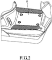
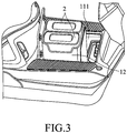
- the electric carrier device 1 includes a footplate 11 and a battery box 12 disposed in a receiving space 111 under the footplate 11.
- the battery box 12 is driven to ascend or descend by a motor (not shown) of the electric carrier device 1.
- the footplate 11 is controlled to be opened when the battery box 12 is driven to ascend, and to be closed when the battery box 12 is driven to descend.
- two removable batteries 2 are placed in the battery box 12, but the number and the type of the batteries 2 are not limited to the disclosure herein and may vary in other embodiments.
- a user of the batteries 2 can take the one of the batteries 2 (referred to as the battery 2 hereinafter) out of the battery box 12 for charging the same at the energy station.
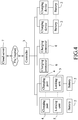
- the energy station includes a controller 3, a plurality of charging ports 4, a plurality of locking units 5 and a plurality of charging connecters 6.
- the controller 3 is communicable with a cloud server 7 over the Internet.
- the cloud server 7 stores a plurality of reference battery identifiers each of which corresponds to a battery and corresponds to one of a first lease code and a second lease code that are different from each other.
- the first lease code represents a long-term lease
- the second lease code represents a short-term lease.
- each of the reference battery identifiers further corresponds to a pick-up password.
- the cloud server 7 further stores a plurality of user end identifiers each corresponding to one or more of the reference battery identifiers.
- Each of the user end identifiers indicates an electronic device.
- the energy station includes an energy station identifier that is to be scanned by an electronic device provided with a camera or a scanner.
- the controller 3 may be implemented by a personal computer, a workstation, or any electronic device/circuit configurable/programmable in a software manner and/or hardware manner to implement functionalities of this disclosure.
- the types of battery lease for renting a battery include the long-term lease which corresponds to renting of the battery 2 for a long period of time and the short-term lease which corresponds to renting of the battery 2 for a short period of time.
- the user who signed the long-term lease may bring the battery 2 to an energy station for battery charging.
- the user who signed the short-term lease may bring a discharged battery 2 to an energy station set up by an electric carrier device (e.g., vehicle) manufacturer for battery swapping.
- an electric carrier device e.g., vehicle
- Each of the charging ports 4 is electrically connected to the controller 3.
- One of the charging ports 4 that is about to charge a battery 2 (e.g., when the charging port 4 that is currently not connected to any battery detects presence of a battery 2 nearby as the battery 2 is brought near the charging port 4) is configured to detect a provided battery identifier of the battery 2 of a user end, and to transmit the provided battery identifier to the controller 3 which relays the provided battery identifier to the cloud server 7, so as to enable the cloud server 7 to determine one of the reference battery identifiers that matches the provided battery identifier, and to determine to which one of the first lease code and the second lease code the one of the reference battery identifiers thus determined corresponds.
- the provided battery identifier is also known as a battery pack serial number, and is usually recorded on the battery 2 for identification purposes by the vehicle manufacturer during battery development.
- the provided battery identifier is represented as a two-dimensional (2D) barcode such as a Quick Response (QR) code.
- the provided battery identifier may be printed as the 2D barcode on a piece of paper pasted on a part of the battery 2 (e.g., a top end of the battery 2) that is easily accessed for being scanned with a scanner of the one of the charging ports 4, or may be stored in an internal storage of the battery 2 for being read via wireless communication between near-field communication (NFC) modules respectively of the battery 2 and the one of the charging ports 4.
- NFC near-field communication
- the internal storage of the battery 2 can be further utilized to record usage-related data of the battery 2 such as power consumption, state of health of the battery, remain capacity, capacity of full charge, voltage of battery, charge/discharge current, cycle count of charge state, charging time, and software/hardware serial numbers of battery.
- the user When purchasing an electric carrier device at a vendor, the user usually logs in to an application program that is launched on the electronic device (e.g., a mobile phone), and registers, at the cloud server 7, user-related data such as the type of battery lease (i.e., the long-term lease or the short-term lease), and the pick-up password for getting the battery 2 back when the battery 2 has been charged up.
- the cloud server 7 generates a user end identifier that is represented as a QR code based on the user-related data, and transmits the user end identifier to the electronic device of the user.
- a computer of the vendor obtains the user end identifier by scanning the QR code displayed on the electronic device of the user, obtains the pick-up password corresponding to the user end identifier by communicating with the cloud server 7, and records the pick-up password in the inner storage of the battery 2 based on NFC communication protocols. In this way, the user-related data and what is stored in the internal storage of the battery 2 is bound together.
- the computer of the vendor obtains the provided battery identifier by scanning the QR code on the battery 2 of the user end, binds the provided battery identifier and the user end identifier together, and transmits the provided battery identifier and the user end identifier which have been bound together to the cloud server 7 so as to enable the cloud server 7 to store the provided battery identifier as a reference battery identifier corresponding to the user end identifier of the user purchasing the electric carrier device at the vendor.
- the cloud server 7 When the user has registered at the cloud server 7, and after the provided battery identifier has been transmitted by the vendor to the cloud server 7, the cloud server 7 establishes a correspondence relationship between the provided battery identifier of the battery 2 of the user (serving as one of the reference battery identifiers in the cloud server 7) and the type of battery lease signed by the user.
- the one of the reference battery identifiers and the first/second lease code are represented as an integrated code. For example, for an integrated code "3510AAGD7981131001", the ninth character "9" from the right side indicates the long-term lease, and for an example of an integrated code "3150AAGD7881131001", the ninth character "8" from the right side indicates the short-term lease.
- the one of the reference battery identifiers and the first/second lease code are represented as two individual codes. Then, the two individual codes are correlated with each other.
- the correspondence relationship between the one of the reference battery identifiers and the first or second lease code i.e., the integrated code or the set of two individual codes) may also be stored in the internal storage of the battery 2.
- the locking units 5 respectively correspond to the charging ports 4, and are switchable between one of a locked state for battery charging and an unlocked state for releasing the battery 2 for pick-up.
- each of the locking units 5 is implemented to be a mechanical lock that is to be manually switched between the locked state and the unlocked state, but implementation of the locking unit 5 is not limited to the disclosure herein and may vary in other embodiments .
- each of the locking units 5 is implemented to be an electronic lock that is to be controlled based on a locking signal that is generated and transmitted by the controller 3 according to a charge signal indicating the result of determination made by the cloud server 7 (determination regarding which one of the reference battery identifiers matches the provided battery identifier, and to which one of the first lease code and the second lease code the one of the reference battery identifiers thus determined corresponds) so as to be switched between the locked state and the unlocked state.
- the locking unit 5 that has been switched to the unlocked state for releasing the battery is automatically switched back to the locked state after a predetermined time period has elapsed during which the battery 2 has not been picked up so as to prevent the battery 2 from being stolen.
- the controller 3 is configured to, when it is determined by the cloud server 7 that the one of the reference battery identifiers thus determined to match the provided battery identifier of the battery 2 of the user end corresponds to the first lease code, receive the charge signal transmitted by the cloud server 7 and to control the one of the charging ports 4 (that was about to charge the battery 2) to charge the battery 2 of the user end.
- the controller 3 is configured to, when it is determined by the cloud server 7 that the one of the reference battery identifiers thus determined corresponds to the first lease code, receive the pick-up password from the cloud server 7 so as to control the one of the charging ports 4 (that was about to charge the battery 2) to charge the battery 2 of the user end.
- one of the locking units 5 corresponding to the one of the charging ports 4 that was about to charge the battery 2 is configured to switch to the locked state, under control of the controller 3 based on the charge signal, so as to lock the battery 2 of the user end which has been put into a battery slot of the one of the charging ports 4, and establish an electrical connection between the battery 2 of the user end and the one of the charging ports 4 for charging the battery 2 of the user end.
- the controller 3 is configured to, when the one of the charging ports 4 has charged up the battery 2 of the user end, transmit a charge-up signal to the cloud server 7 so as to enable the cloud server 7 to transmit, based on the charge-up signal, a pick-up message to the controller 3 of the energy station and to an electronic device indicated by a user end identifier corresponding to the one of the reference battery identifiers thus determined by the cloud server 7.
- Each of the charging connecters 6 is electrically connected to the controller 3 and is configured to charge an electric carrier device.
- the energy station further includes a plurality of charging devices each of which is configured to directly charge the battery 2 as shown in Figure 4 .
- FIG. 5 an embodiment of a method of battery charging according to the disclosure is illustrated.
- the method is to be implemented by the energy station that is previously described.
- the method includes steps 91 to 98 described as follows.
- step 91 one of the charging ports 4, which is about to charge the battery 2 of the user end that is to be recharged or swapped (referred to hereinafter as the corresponding one of the charging ports 4) (for instance, the battery 2 is brought into physical contact with the corresponding one of the charging ports 4 and the locking unit 5 that corresponds to the corresponding one of the charging ports 4 is still in the unlocked state so no electrical connection between the battery 2 and the corresponding one of the charging ports 4 has been established), of the energy station detects the provided battery identifier of the battery 2 of the user end, and transmits the provided battery identifier to the controller 3.
- the corresponding one of the charging ports 4 for instance, the battery 2 is brought into physical contact with the corresponding one of the charging ports 4 and the locking unit 5 that corresponds to the corresponding one of the charging ports 4 is still in the unlocked state so no electrical connection between the battery 2 and the corresponding one of the charging ports 4 has been established
- the energy station detects the provided battery identifier of the battery 2 of the user end, and transmits the
- step 92 the controller 3 of the energy station transmits the provided battery identifier to the cloud server 7 so as to enable the cloud server 7 to determine one of the reference battery identifiers that matches the provided battery identifier, and to determine to which one of the first lease code and the second lease code the one of the reference battery identifiers thus determined corresponds.
- the cloud server 7 determines that the one of the reference battery identifiers thus determined corresponds to the first lease code (i.e., the long-term lease)
- the battery 2 is allowed to be charged by the corresponding one of the charging ports 4, and a flow of procedure of this method proceeds to step 93.
- the cloud server 7 determines that the one of the reference battery identifiers thus determined corresponds to the second lease code (i.e., the short-term lease)
- the battery 2 belongs to the short-term lease and may be swapped for a fully-charged battery, and the flow proceeds to step 97.
- step 93 the energy station is controlled to charge the battery 2 of the user end.
- step 93 includes sub-steps 931 and 932 described as follows.
- the controller 3 receives the charge signal transmitted by the cloud server 7 when it is determined by the cloud server 7 that the one of the reference battery identifiers thus determined corresponds to the first lease code.
- the cloud server 7 further transmits the charge signal to the electronic device indicated by the user end identifier corresponding to the one of the reference battery identifiers thus determined.
- sub-step 932 under control of the controller 3 and based on the charge signal, one of the locking units 5 which corresponds to the corresponding one of the charging ports 4 is enabled to be switched to the locked state so as to lock the battery 2 of the user end to the corresponding one of the charging ports 4 and establish an electrical connection between the battery 2 of the user end and the corresponding one of the charging ports 4 for charging the battery 2 of the user end.
- the user who possesses the electronic device receiving the charge signal from the cloud server 7 may be prompted to manually operate the one of the locking units 5 to switch to the locked state.
- an indicating light (not shown) corresponding to the corresponding one of the charging ports 4 which is connected to the battery 2 of the user end will be triggered to emit light.
- implementation of state-of-charge indication is not limited to the disclosure herein and may vary in other embodiments.
- the controller 3 of the energy station when it is determined by the cloud server 7 that the one of the reference battery identifiers thus determined corresponds to the first lease code, the controller 3 of the energy station receives the pick-up password corresponding to the battery 2 of the user end from the cloud server 7 so as to be controlled to charge the battery 2 of the user end by transmitting the locking signal to switch the one the locking units 5, that is implemented to be the electronic lock, to the locked state.
- the cloud server 7 controls the energy station to charge the battery 2 is not limited to the disclosure herein and may vary in other embodiments.
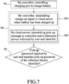
- step 94 when the corresponding one of the charging ports 4 has charged up the battery 2 of the user end, the controller 3 of the energy station enables the cloud server 7 to transmit the pick-up message to the controller 3 and to the electronic device (e.g., the mobile device) indicated by one of the user end identifiers corresponding to the one of the reference battery identifiers thus determined.
- the electronic device e.g., the mobile device
- step 94 includes sub-steps 941 and 942 described as follows.
- sub-step 941 when the corresponding one of the charging ports 4 has charged up the battery 2 of the user end, the controller 3 transmits the charge-up signal to the cloud server 7.
- the cloud server 7 transmits, based on the charge-up signal, the pick-up message to the controller 3 of the energy station and to the electronic device (i.e., the mobile device) indicated by the one of the user end identifiers corresponding to the one of the reference battery identifiers thus determined. Notified by the pick-up message, the user is prompted to input the pick-up password in order to pick up the battery 2 that has been charged up at the energy station.
- step 95 the controller 3 obtains the pick-up password via input from the user end, and transmits the pick-up password thus obtained to the cloud server 7 so as to enable the cloud server 7 to determine whether the pick-up password received from the controller 3 matches the pick-up password corresponding to the one of the reference battery identifiers stored in the cloud server 7.
- the controller 3 is configured to determine whether the pick-up password obtained from the user end matches the pick-up password stored in the battery 2 of the user end.
- step 96 the controller 3 permits the battery 2 of the user end to be picked up when it is determined by the cloud server 7 that the pick-up password received from the controller 3 matches the pick-up password corresponding to the one of the reference battery identifiers, or when it is determined by the controller 3 that the pick-up password obtained from the user end matches the pick-up password stored in the battery 2.
- the one of the locking units 5 may be operated by the user to switch to the unlocked state so as to release the battery 2 of the user end for pick-up and to cut off the electrical connection between the battery 2 and the corresponding one of the charging ports 4. At this moment, the corresponding indicating light is off. It should be noted that implementation of releasing the battery 2 is not limited to the disclosure herein and may vary in other embodiments.
- step 97 when it is determined by the cloud server 7 in step 92 that the one of the reference battery identifiers thus determined corresponds to the second lease code, the cloud server 7 transmits a prompt message to the electronic device indicated by one of the user end identifiers corresponding to the one of the reference battery identifiers thus determined, so as to prompt the user to operate the electronic device to perform scanning of the energy station identifier (which may be represented as a QR code) of the energy station by the application program that is launched on the electronic device and that is provided by the vehicle manufacturer, and to then transmit the energy station identifier to the cloud server 7.
- the energy station identifier which may be represented as a QR code
- the cloud server 7 controls the controller 3 of the energy station corresponding to the energy station identifier to display a replacement message.
- the replace message prompts replacement of the battery 2 of the user end with another fully-charged battery stored in the energy station.
- the replacement message may be displayed to indicate which one of the charging ports 4 said another fully-charged battery is disposed, and after swapping the two batteries, the one of the charging ports 4 (now coupled to the battery 2 that has run out) is controlled by the controller 3 to charge the battery 2.
- the number of battery a single user is allowed to rent under the short-term lease is not limited to one and may vary depending on demands of the user end.
- the energy station includes a controller 3 configured to communicate with a cloud server 7 over the Internet, and a plurality of charging ports 4 each of which is electrically connected to the controller 3.
- the cloud server 7 stores a plurality of reference battery identifiers each of which corresponds to a battery and a user end identifier, and corresponds to one of a first lease code and a second lease code.
- One of the charging ports 4 is configured to charge a battery 2 of a user end which has a provided battery identifier matching one of the reference battery identifiers that corresponds to the first lease code.
- the controller 3 is configured to scan a user barcode that is displayed by an electronic device of the user end and that represents a user end identifier of the user end so as to obtain the user end identifier of the user end.
- the user barcode is a QR code, and is displayed by the electronic device of the user end when an application program is launched on the electronic device and is logged in to.
- the controller 3 is configured to transmit the user end identifier thus obtained over the Internet to the cloud server 7 so as to enable the cloud server 7 to determine whether the user end identifier received from the controller 3 matches the user end identifier corresponding to the one of the reference battery identifiers stored in the cloud server 7.
- the one of the reference battery identifiers and the first lease code are represented as one of an integrated code and a set of two individual codes.
- the controller 3 is further configured to permit the battery 2 of the user end to be picked up when it is determined by the cloud server 7 that the user end identifier received from the controller 3 matches the user end identifier corresponding to the one of the reference battery identifiers.
- the controller 3 also stores the reference battery identifiers each of which corresponds to a user end identifier.
- the controller 3 is configured to determine whether the user end identifier obtained by the controller 3 matches the user end identifier corresponding to the one of the reference battery identifiers stored in the controller 3 and matching the provided battery identifier of the battery 2, and to permit the battery 2 of the user end to be picked up when it is determined by the controller 3 that the user end identifier obtained by the controller 3 matches the user end identifier corresponding to the one of the reference battery identifiers.
- the energy station includes a controller 3 configured to communicate with a cloud server 7 over the Internet, and a plurality of charging ports 4 each of which is electrically connected to the controller 3.
- the cloud server 7 stores a plurality of reference battery identifiers each of which corresponds to a battery and a user end identifier, and corresponds to one of a first lease code and a second lease code.
- One of the reference battery identifiers corresponding to the second lease code and the second lease code are represented as one of an integrated code and a set of two individual codes.
- One of the charging ports 4 is connected to a battery which has a provided battery identifier matching one of the reference battery identifiers that corresponds to the second lease code.
- the controller 3 is configured to scan a user barcode that is displayed by an electronic device of the user end and that represents a user end identifier of the user end so as to obtain the user end identifier of the user end.
- the user barcode is a QR code, and is displayed by the electronic device of the user end when an application program is launched on the electronic device and is logged in to.
- the controller 3 is configured to transmit the user end identifier thus obtained over the Internet to the cloud server 7 so as to enable the cloud server 7 to determine whether the user end identifier received from the controller 3 matches the user end identifier corresponding to the one of the reference battery identifiers .
- the controller 3 is configured to permit the battery connected to the one of the charging ports 4 to be picked up when it is determined by the cloud server 7 that the user end identifier received from the controller 3 matches the user end identifier corresponding to the one of the reference battery identifiers.
- the method of battery charging utilizes the energy station to detect the provided battery identifier of the battery 2 of the user end, and to transmit the provided battery identifier to the cloud server 7 so as to enable the cloud server 7 to make a determination about which kind of lease the battery corresponds to. Based on a result of the determination, the energy station is controlled to charge the battery 2 of the user end or to allow battery swapping. Therefore, it is not necessary for the user of the battery 2 to know which kind of lease the battery 2 belongs to, and the energy station will automatically charge the battery 2 or allow battery swapping, which is convenient.
- the locking unit 5 corresponding to one of the charging ports 4 about to charge the battery 2 is able to lock the battery 2 to the one of the charging ports 4, and to release the battery 2 after the battery 2 has been charged up and the pick-up password is correctly entered.
Landscapes
- Engineering & Computer Science (AREA)
- Power Engineering (AREA)
- Business, Economics & Management (AREA)
- Mechanical Engineering (AREA)
- Transportation (AREA)
- Economics (AREA)
- Theoretical Computer Science (AREA)
- Strategic Management (AREA)
- Physics & Mathematics (AREA)
- General Physics & Mathematics (AREA)
- Human Resources & Organizations (AREA)
- Marketing (AREA)
- General Business, Economics & Management (AREA)
- Entrepreneurship & Innovation (AREA)
- Accounting & Taxation (AREA)
- Development Economics (AREA)
- Tourism & Hospitality (AREA)
- Finance (AREA)
- Computer Security & Cryptography (AREA)
- Health & Medical Sciences (AREA)
- Game Theory and Decision Science (AREA)
- Operations Research (AREA)
- Educational Administration (AREA)
- Quality & Reliability (AREA)
- General Engineering & Computer Science (AREA)
- Computer Hardware Design (AREA)
- Software Systems (AREA)
- Signal Processing (AREA)
- Computer Networks & Wireless Communication (AREA)
- Public Health (AREA)
- Water Supply & Treatment (AREA)
- General Health & Medical Sciences (AREA)
- Primary Health Care (AREA)
- Charge And Discharge Circuits For Batteries Or The Like (AREA)
- Secondary Cells (AREA)
- Electric Propulsion And Braking For Vehicles (AREA)
Abstract
Description
- The disclosure relates to a method of battery charging and an energy station, and more particularly to a method of battery charging and an energy station for removable batteries.
- Conventionally, information regarding which one of a long-term lease and a short-term lease a battery of an electric carrier device belongs to may be unknown to a user of the electric carrier device (e.g., if the user is not the owner of the electric carrier device) unless the user takes the battery to an energy station or a vendor, where a battery registered with the long-term lease needs to be recharged at the vendor, and a battery registered with the short-term lease needs to be swapped at the energy station. This is inconvenient and adversely influences popularization of electric carrier devices.
- Therefore, an object of the disclosure is to provide a method of battery charging and an energy station that can alleviate at least one of the drawbacks of the prior art.
- According to a first aspect of the disclosure, the method of battery charging is to be implemented by an energy station. The energy station is communicable with a cloud server over the Internet. The cloud server stores a plurality of reference battery identifiers each of which corresponds to a battery and corresponds to one of a first lease code and a second lease code. The method includes:
- a) detecting a provided battery identifier of a battery of a user end, and transmitting the provided battery identifier to the cloud server so as to enable the cloud server to determine one of the reference battery identifiers that matches the provided battery identifier, and to determine to which one of the first lease code and the second lease code the one of the reference battery identifiers thus determined corresponds; and
- b) when it is determined that the one of the reference battery identifiers thus determined corresponds to the first lease code, being controlled to charge the battery of the user end.
- According to a second aspect of the disclosure, the energy station includes a controller and a plurality of charging ports. The controller is communicable with a cloud server over the Internet. The cloud server stores a plurality of reference battery identifiers each of which corresponds to a battery and corresponds to one of a first lease code and a second lease code. Each of the charging ports is electrically connected to the controller. One of the charging ports that is about to charge a battery of a user end is configured to detect a provided battery identifier of the battery, and to transmit the provided battery identifier to the controller which relays the provided battery identifier to the cloud server so as to enable the cloud server to determine one of the reference battery identifiers that matches the provided battery identifier, and to determine to which one of the first lease code and the second lease code the one of the reference battery identifiers thus determined corresponds. The controller is configured to, when it is determined by the cloud server that the one of the reference battery identifiers thus determined corresponds to the first lease code, control the one of the charging ports to charge the battery of the user end.
- According to a third aspect of the disclosure, the energy station includes a controller and a plurality of charging ports. The controller is communicable with a cloud server over the Internet. The cloud server stores a plurality of reference battery identifiers each of which corresponds to a battery and a pick-up password, and corresponds to one of a first lease code and a second lease code. Each of the charging ports is electrically connected to the controller. One of the charging ports is configured to charge a battery of a user end which has a provided battery identifier matching one of the reference battery identifiers that corresponds to the first lease code. The controller is configured to obtain a pick-up password via input from the user end, transmit the pick-up password thus obtained to the cloud server so as to enable the cloud server to determine whether the pick-up password received from the controller matches the pick-up password corresponding to the one of the reference battery identifiers stored in the cloud server, and permit the battery of the user end to be picked up when it is determined by the cloud server that the pick-up password received from the controller matches the pick-up password corresponding to the one of the reference battery identifiers, or when it is determined by the controller that the pick-up password obtained from the user end matches a pick-up password stored in the battery.
- According to a fourth aspect of the disclosure, the energy station includes a controller and a plurality of charging ports. The controller is configured to communicate with a cloud server over the Internet. The cloud server stores a plurality of reference battery identifiers each of which corresponds to a battery and a user end identifier, and corresponds to one of a first lease code and a second lease code. Each of the charging ports is electrically connected to the controller. One of the charging ports is configured to charge a battery of a user end which has a provided battery identifier matching one of the reference battery identifiers that corresponds to the first lease code. The controller is configured to scan a user barcode that is displayed by an electronic device of the user end and that represents a user end identifier of the user end so as to obtain the user end identifier of the user end, transmit the user end identifier thus obtained over the Internet to the cloud server so as to enable the cloud server to determine whether the user end identifier received from the controller matches the user end identifier corresponding to the one of the reference battery identifiers stored in the cloud server, and permit the battery of the user end to be picked up when it is determined by the cloud server that the user end identifier received from the controller matches the user end identifier corresponding to the one of the reference battery identifiers.
- According to a fifth aspect of the disclosure, the energy station includes a controller and a plurality of charging ports. The controller is configured to communicate with a cloud server over the Internet. The cloud server stores a plurality of reference battery identifiers each of which corresponds to a battery and a user end identifier, and corresponds to one of a first lease code and a second lease code. Each of the charging ports is electrically connected to the controller. One of the charging ports is connected to a battery which has a provided battery identifier matching one of the reference battery identifiers that corresponds to the second lease code. The controller is configured to scan a user barcode that is displayed by an electronic device of the user end and that represents a user end identifier of the user end so as to obtain the user end identifier of the user end, transmit the user end identifier thus obtained over the Internet to the cloud server so as to enable the cloud server to determine whether the user end identifier received from the controller matches the user end identifier corresponding to the one of the reference battery identifiers, and permit the battery provided on the one of the charging ports to be picked up when it is determined by the cloud server that the user end identifier received from the controller matches the user end identifier corresponding to the one of the reference battery identifiers.
- Other features and advantages of the disclosure will become apparent in the following detailed description of the embodiment with reference to the accompanying drawings, of which:
-
Figure 1 is a side schematic view illustrating an embodiment of an electric carrier device that includes a battery to be charged by an energy station according to the disclosure; -
Figure 2 is a fragmentary perspective schematic view illustrating an embodiment of a footplate of the electric carrier device; -
Figure 3 is a fragmentary perspective schematic view illustrating an embodiment of two removable batteries placed in a battery box under the footplate of the electric carrier device; -
Figure 4 is a block diagram illustrating an embodiment of the energy station according to the disclosure; -
Figure 5 is a flow chart illustrating an embodiment of a method of battery charging according to the disclosure; -
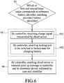
Figure 6 is a flow chart illustrating an embodiment of control of battery charging of the method according to the disclosure; and -
Figure 7 is a flow chart illustrating an embodiment of transmission of a pick-up message of the method according to the disclosure. - Before the disclosure is described in greater detail, it should be noted that where considered appropriate, reference numerals or terminal portions of reference numerals have been repeated among the figures to indicate corresponding or analogous elements, which may optionally have similar characteristics.
- Referring to
Figures 1 to 3 , an embodiment of anelectric carrier device 1 that includes abattery 2 to be recharged by an energy station according to the disclosure is illustrated. In this embodiment, theelectric carrier device 1 is implemented to be an electric motorcycle or an electric scooter, but implementation of theelectric carrier device 1 is not limited to the disclosure herein and may vary in other embodiments. Theelectric carrier device 1 includes afootplate 11 and abattery box 12 disposed in areceiving space 111 under thefootplate 11. Thebattery box 12 is driven to ascend or descend by a motor (not shown) of theelectric carrier device 1. Thefootplate 11 is controlled to be opened when thebattery box 12 is driven to ascend, and to be closed when thebattery box 12 is driven to descend. In this embodiment, tworemovable batteries 2 are placed in thebattery box 12, but the number and the type of thebatteries 2 are not limited to the disclosure herein and may vary in other embodiments. When one of thebatteries 2 is running out, a user of thebatteries 2 can take the one of the batteries 2 (referred to as thebattery 2 hereinafter) out of thebattery box 12 for charging the same at the energy station. - Referring to
Figure 4 , an embodiment of the energy station according to the disclosure is illustrated. The energy station includes a controller 3, a plurality ofcharging ports 4, a plurality oflocking units 5 and a plurality of charging connecters 6. - The controller 3 is communicable with a
cloud server 7 over the Internet. Thecloud server 7 stores a plurality of reference battery identifiers each of which corresponds to a battery and corresponds to one of a first lease code and a second lease code that are different from each other. In this embodiment, the first lease code represents a long-term lease, and the second lease code represents a short-term lease. In addition, each of the reference battery identifiers further corresponds to a pick-up password. Thecloud server 7 further stores a plurality of user end identifiers each corresponding to one or more of the reference battery identifiers. Each of the user end identifiers indicates an electronic device. In addition, the energy station includes an energy station identifier that is to be scanned by an electronic device provided with a camera or a scanner. - The controller 3 may be implemented by a personal computer, a workstation, or any electronic device/circuit configurable/programmable in a software manner and/or hardware manner to implement functionalities of this disclosure.
- It is worthy to note that since the
battery 2 of theelectric carrier device 1 is expensive due to cost of production, the user of theelectric carrier device 1 usually rents thebattery 2 instead of buying one. The types of battery lease for renting a battery include the long-term lease which corresponds to renting of thebattery 2 for a long period of time and the short-term lease which corresponds to renting of thebattery 2 for a short period of time. To recharge thebattery 2, the user who signed the long-term lease may bring thebattery 2 to an energy station for battery charging. On the other hand, the user who signed the short-term lease may bring a dischargedbattery 2 to an energy station set up by an electric carrier device (e.g., vehicle) manufacturer for battery swapping. - Each of the
charging ports 4 is electrically connected to the controller 3. One of the chargingports 4 that is about to charge a battery 2 (e.g., when the chargingport 4 that is currently not connected to any battery detects presence of abattery 2 nearby as thebattery 2 is brought near the charging port 4) is configured to detect a provided battery identifier of thebattery 2 of a user end, and to transmit the provided battery identifier to the controller 3 which relays the provided battery identifier to thecloud server 7, so as to enable thecloud server 7 to determine one of the reference battery identifiers that matches the provided battery identifier, and to determine to which one of the first lease code and the second lease code the one of the reference battery identifiers thus determined corresponds. - The provided battery identifier is also known as a battery pack serial number, and is usually recorded on the
battery 2 for identification purposes by the vehicle manufacturer during battery development. The provided battery identifier is represented as a two-dimensional (2D) barcode such as a Quick Response (QR) code. The provided battery identifier may be printed as the 2D barcode on a piece of paper pasted on a part of the battery 2 (e.g., a top end of the battery 2) that is easily accessed for being scanned with a scanner of the one of the chargingports 4, or may be stored in an internal storage of thebattery 2 for being read via wireless communication between near-field communication (NFC) modules respectively of thebattery 2 and the one of the chargingports 4. It is worth to note that after theelectric carrier device 1 has started being powered by thebattery 2, the internal storage of thebattery 2 can be further utilized to record usage-related data of thebattery 2 such as power consumption, state of health of the battery, remain capacity, capacity of full charge, voltage of battery, charge/discharge current, cycle count of charge state, charging time, and software/hardware serial numbers of battery. - When purchasing an electric carrier device at a vendor, the user usually logs in to an application program that is launched on the electronic device (e.g., a mobile phone), and registers, at the
cloud server 7, user-related data such as the type of battery lease (i.e., the long-term lease or the short-term lease), and the pick-up password for getting thebattery 2 back when thebattery 2 has been charged up. Thecloud server 7 generates a user end identifier that is represented as a QR code based on the user-related data, and transmits the user end identifier to the electronic device of the user. Thereafter, a computer of the vendor obtains the user end identifier by scanning the QR code displayed on the electronic device of the user, obtains the pick-up password corresponding to the user end identifier by communicating with thecloud server 7, and records the pick-up password in the inner storage of thebattery 2 based on NFC communication protocols. In this way, the user-related data and what is stored in the internal storage of thebattery 2 is bound together. - In one embodiment, the computer of the vendor obtains the provided battery identifier by scanning the QR code on the
battery 2 of the user end, binds the provided battery identifier and the user end identifier together, and transmits the provided battery identifier and the user end identifier which have been bound together to thecloud server 7 so as to enable thecloud server 7 to store the provided battery identifier as a reference battery identifier corresponding to the user end identifier of the user purchasing the electric carrier device at the vendor. - When the user has registered at the
cloud server 7, and after the provided battery identifier has been transmitted by the vendor to thecloud server 7, thecloud server 7 establishes a correspondence relationship between the provided battery identifier of thebattery 2 of the user (serving as one of the reference battery identifiers in the cloud server 7) and the type of battery lease signed by the user. Specifically speaking, in a first approach, the one of the reference battery identifiers and the first/second lease code are represented as an integrated code. For example, for an integrated code "3510AAGD7981131001", the ninth character "9" from the right side indicates the long-term lease, and for an example of an integrated code "3150AAGD7881131001", the ninth character "8" from the right side indicates the short-term lease. In a second approach, the one of the reference battery identifiers and the first/second lease code are represented as two individual codes. Then, the two individual codes are correlated with each other. The correspondence relationship between the one of the reference battery identifiers and the first or second lease code (i.e., the integrated code or the set of two individual codes) may also be stored in the internal storage of thebattery 2. - The locking
units 5 respectively correspond to the chargingports 4, and are switchable between one of a locked state for battery charging and an unlocked state for releasing thebattery 2 for pick-up. In this embodiment, each of the lockingunits 5 is implemented to be a mechanical lock that is to be manually switched between the locked state and the unlocked state, but implementation of thelocking unit 5 is not limited to the disclosure herein and may vary in other embodiments . For example, in one embodiment, each of the lockingunits 5 is implemented to be an electronic lock that is to be controlled based on a locking signal that is generated and transmitted by the controller 3 according to a charge signal indicating the result of determination made by the cloud server 7 (determination regarding which one of the reference battery identifiers matches the provided battery identifier, and to which one of the first lease code and the second lease code the one of the reference battery identifiers thus determined corresponds) so as to be switched between the locked state and the unlocked state. In this embodiment, thelocking unit 5 that has been switched to the unlocked state for releasing the battery is automatically switched back to the locked state after a predetermined time period has elapsed during which thebattery 2 has not been picked up so as to prevent thebattery 2 from being stolen. - The controller 3 is configured to, when it is determined by the
cloud server 7 that the one of the reference battery identifiers thus determined to match the provided battery identifier of thebattery 2 of the user end corresponds to the first lease code, receive the charge signal transmitted by thecloud server 7 and to control the one of the charging ports 4 (that was about to charge the battery 2) to charge thebattery 2 of the user end. - In one embodiment, the controller 3 is configured to, when it is determined by the
cloud server 7 that the one of the reference battery identifiers thus determined corresponds to the first lease code, receive the pick-up password from thecloud server 7 so as to control the one of the charging ports 4 (that was about to charge the battery 2) to charge thebattery 2 of the user end. - Specifically speaking, one of the locking
units 5 corresponding to the one of the chargingports 4 that was about to charge thebattery 2 is configured to switch to the locked state, under control of the controller 3 based on the charge signal, so as to lock thebattery 2 of the user end which has been put into a battery slot of the one of the chargingports 4, and establish an electrical connection between thebattery 2 of the user end and the one of the chargingports 4 for charging thebattery 2 of the user end. - The controller 3 is configured to, when the one of the charging
ports 4 has charged up thebattery 2 of the user end, transmit a charge-up signal to thecloud server 7 so as to enable thecloud server 7 to transmit, based on the charge-up signal, a pick-up message to the controller 3 of the energy station and to an electronic device indicated by a user end identifier corresponding to the one of the reference battery identifiers thus determined by thecloud server 7. - Each of the charging connecters 6 is electrically connected to the controller 3 and is configured to charge an electric carrier device.
- In one embodiment, the energy station further includes a plurality of charging devices each of which is configured to directly charge the
battery 2 as shown inFigure 4 . - Referring to
Figure 5 , an embodiment of a method of battery charging according to the disclosure is illustrated. The method is to be implemented by the energy station that is previously described. The method includessteps 91 to 98 described as follows. - In
step 91, one of the chargingports 4, which is about to charge thebattery 2 of the user end that is to be recharged or swapped (referred to hereinafter as the corresponding one of the charging ports 4) (for instance, thebattery 2 is brought into physical contact with the corresponding one of the chargingports 4 and thelocking unit 5 that corresponds to the corresponding one of the chargingports 4 is still in the unlocked state so no electrical connection between thebattery 2 and the corresponding one of the chargingports 4 has been established), of the energy station detects the provided battery identifier of thebattery 2 of the user end, and transmits the provided battery identifier to the controller 3. - In
step 92, the controller 3 of the energy station transmits the provided battery identifier to thecloud server 7 so as to enable thecloud server 7 to determine one of the reference battery identifiers that matches the provided battery identifier, and to determine to which one of the first lease code and the second lease code the one of the reference battery identifiers thus determined corresponds. When it is determined by thecloud server 7 that the one of the reference battery identifiers thus determined corresponds to the first lease code (i.e., the long-term lease), it means that thebattery 2 is allowed to be charged by the corresponding one of the chargingports 4, and a flow of procedure of this method proceeds to step 93. On the other hand, when it is determined by thecloud server 7 that the one of the reference battery identifiers thus determined corresponds to the second lease code (i.e., the short-term lease), it means that thebattery 2 belongs to the short-term lease and may be swapped for a fully-charged battery, and the flow proceeds to step 97. - In
step 93, the energy station is controlled to charge thebattery 2 of the user end. Specifically speaking, referring toFigure 6 ,step 93 includessub-steps - In
sub-step 931, the controller 3 receives the charge signal transmitted by thecloud server 7 when it is determined by thecloud server 7 that the one of the reference battery identifiers thus determined corresponds to the first lease code. Thecloud server 7 further transmits the charge signal to the electronic device indicated by the user end identifier corresponding to the one of the reference battery identifiers thus determined. - In
sub-step 932, under control of the controller 3 and based on the charge signal, one of the lockingunits 5 which corresponds to the corresponding one of the chargingports 4 is enabled to be switched to the locked state so as to lock thebattery 2 of the user end to the corresponding one of the chargingports 4 and establish an electrical connection between thebattery 2 of the user end and the corresponding one of the chargingports 4 for charging thebattery 2 of the user end. The user who possesses the electronic device receiving the charge signal from thecloud server 7 may be prompted to manually operate the one of the lockingunits 5 to switch to the locked state. - In this embodiment, when the electrical connection for charging the
battery 2 is established, an indicating light (not shown) corresponding to the corresponding one of the chargingports 4 which is connected to thebattery 2 of the user end will be triggered to emit light. However, implementation of state-of-charge indication is not limited to the disclosure herein and may vary in other embodiments. - In one embodiment, when it is determined by the
cloud server 7 that the one of the reference battery identifiers thus determined corresponds to the first lease code, the controller 3 of the energy station receives the pick-up password corresponding to thebattery 2 of the user end from thecloud server 7 so as to be controlled to charge thebattery 2 of the user end by transmitting the locking signal to switch the one thelocking units 5, that is implemented to be the electronic lock, to the locked state. It should be noted that the way that thecloud server 7 controls the energy station to charge thebattery 2 is not limited to the disclosure herein and may vary in other embodiments. - Referring back to
Figure 5 , instep 94, when the corresponding one of the chargingports 4 has charged up thebattery 2 of the user end, the controller 3 of the energy station enables thecloud server 7 to transmit the pick-up message to the controller 3 and to the electronic device (e.g., the mobile device) indicated by one of the user end identifiers corresponding to the one of the reference battery identifiers thus determined. - Specifically speaking, referring to
Figure 7 ,step 94 includessub-steps - In
sub-step 941, when the corresponding one of the chargingports 4 has charged up thebattery 2 of the user end, the controller 3 transmits the charge-up signal to thecloud server 7. - In
sub-step 942, thecloud server 7 transmits, based on the charge-up signal, the pick-up message to the controller 3 of the energy station and to the electronic device (i.e., the mobile device) indicated by the one of the user end identifiers corresponding to the one of the reference battery identifiers thus determined. Notified by the pick-up message, the user is prompted to input the pick-up password in order to pick up thebattery 2 that has been charged up at the energy station. - Referring back to
Figure 5 , instep 95, the controller 3 obtains the pick-up password via input from the user end, and transmits the pick-up password thus obtained to thecloud server 7 so as to enable thecloud server 7 to determine whether the pick-up password received from the controller 3 matches the pick-up password corresponding to the one of the reference battery identifiers stored in thecloud server 7. Alternatively, in a variation of this embodiment, the controller 3 is configured to determine whether the pick-up password obtained from the user end matches the pick-up password stored in thebattery 2 of the user end. - In
step 96, the controller 3 permits thebattery 2 of the user end to be picked up when it is determined by thecloud server 7 that the pick-up password received from the controller 3 matches the pick-up password corresponding to the one of the reference battery identifiers, or when it is determined by the controller 3 that the pick-up password obtained from the user end matches the pick-up password stored in thebattery 2. Then, the one of the lockingunits 5 may be operated by the user to switch to the unlocked state so as to release thebattery 2 of the user end for pick-up and to cut off the electrical connection between thebattery 2 and the corresponding one of the chargingports 4. At this moment, the corresponding indicating light is off. It should be noted that implementation of releasing thebattery 2 is not limited to the disclosure herein and may vary in other embodiments. - In
step 97, when it is determined by thecloud server 7 instep 92 that the one of the reference battery identifiers thus determined corresponds to the second lease code, thecloud server 7 transmits a prompt message to the electronic device indicated by one of the user end identifiers corresponding to the one of the reference battery identifiers thus determined, so as to prompt the user to operate the electronic device to perform scanning of the energy station identifier (which may be represented as a QR code) of the energy station by the application program that is launched on the electronic device and that is provided by the vehicle manufacturer, and to then transmit the energy station identifier to thecloud server 7. - In
step 98, based on the energy station identifier, thecloud server 7 controls the controller 3 of the energy station corresponding to the energy station identifier to display a replacement message. The replace message prompts replacement of thebattery 2 of the user end with another fully-charged battery stored in the energy station. The replacement message may be displayed to indicate which one of the chargingports 4 said another fully-charged battery is disposed, and after swapping the two batteries, the one of the charging ports 4 (now coupled to thebattery 2 that has run out) is controlled by the controller 3 to charge thebattery 2. It is worth to note that, the number of battery a single user is allowed to rent under the short-term lease is not limited to one and may vary depending on demands of the user end. - In one embodiment, the energy station includes a controller 3 configured to communicate with a
cloud server 7 over the Internet, and a plurality of chargingports 4 each of which is electrically connected to the controller 3. Thecloud server 7 stores a plurality of reference battery identifiers each of which corresponds to a battery and a user end identifier, and corresponds to one of a first lease code and a second lease code. One of the chargingports 4 is configured to charge abattery 2 of a user end which has a provided battery identifier matching one of the reference battery identifiers that corresponds to the first lease code. The controller 3 is configured to scan a user barcode that is displayed by an electronic device of the user end and that represents a user end identifier of the user end so as to obtain the user end identifier of the user end. In this embodiment, the user barcode is a QR code, and is displayed by the electronic device of the user end when an application program is launched on the electronic device and is logged in to. The controller 3 is configured to transmit the user end identifier thus obtained over the Internet to thecloud server 7 so as to enable thecloud server 7 to determine whether the user end identifier received from the controller 3 matches the user end identifier corresponding to the one of the reference battery identifiers stored in thecloud server 7. The one of the reference battery identifiers and the first lease code are represented as one of an integrated code and a set of two individual codes. The controller 3 is further configured to permit thebattery 2 of the user end to be picked up when it is determined by thecloud server 7 that the user end identifier received from the controller 3 matches the user end identifier corresponding to the one of the reference battery identifiers. - In a variant of this embodiment, the controller 3 also stores the reference battery identifiers each of which corresponds to a user end identifier. The controller 3 is configured to determine whether the user end identifier obtained by the controller 3 matches the user end identifier corresponding to the one of the reference battery identifiers stored in the controller 3 and matching the provided battery identifier of the
battery 2, and to permit thebattery 2 of the user end to be picked up when it is determined by the controller 3 that the user end identifier obtained by the controller 3 matches the user end identifier corresponding to the one of the reference battery identifiers. - In one embodiment, the energy station includes a controller 3 configured to communicate with a
cloud server 7 over the Internet, and a plurality of chargingports 4 each of which is electrically connected to the controller 3. Thecloud server 7 stores a plurality of reference battery identifiers each of which corresponds to a battery and a user end identifier, and corresponds to one of a first lease code and a second lease code. One of the reference battery identifiers corresponding to the second lease code and the second lease code are represented as one of an integrated code and a set of two individual codes. One of the chargingports 4 is connected to a battery which has a provided battery identifier matching one of the reference battery identifiers that corresponds to the second lease code. The controller 3 is configured to scan a user barcode that is displayed by an electronic device of the user end and that represents a user end identifier of the user end so as to obtain the user end identifier of the user end. In this embodiment, the user barcode is a QR code, and is displayed by the electronic device of the user end when an application program is launched on the electronic device and is logged in to. The controller 3 is configured to transmit the user end identifier thus obtained over the Internet to thecloud server 7 so as to enable thecloud server 7 to determine whether the user end identifier received from the controller 3 matches the user end identifier corresponding to the one of the reference battery identifiers . The controller 3 is configured to permit the battery connected to the one of the chargingports 4 to be picked up when it is determined by thecloud server 7 that the user end identifier received from the controller 3 matches the user end identifier corresponding to the one of the reference battery identifiers. - In summary, the method of battery charging according to the disclosure utilizes the energy station to detect the provided battery identifier of the
battery 2 of the user end, and to transmit the provided battery identifier to thecloud server 7 so as to enable thecloud server 7 to make a determination about which kind of lease the battery corresponds to. Based on a result of the determination, the energy station is controlled to charge thebattery 2 of the user end or to allow battery swapping. Therefore, it is not necessary for the user of thebattery 2 to know which kind of lease thebattery 2 belongs to, and the energy station will automatically charge thebattery 2 or allow battery swapping, which is convenient. In addition, thelocking unit 5 corresponding to one of the chargingports 4 about to charge thebattery 2 is able to lock thebattery 2 to the one of the chargingports 4, and to release thebattery 2 after thebattery 2 has been charged up and the pick-up password is correctly entered. - In the description above, for the purposes of explanation, numerous specific details have been set forth in order to provide a thorough understanding of the embodiment. It will be apparent, however, to one skilled in the art, that one or more other embodiments may be practiced without some of these specific details. It should also be appreciated that reference throughout this specification to "one embodiment," "an embodiment," an embodiment with an indication of an ordinal number and so forth means that a particular feature, structure, or characteristic may be included in the practice of the disclosure. It should be further appreciated that in the description, various features are sometimes grouped together in a single embodiment, figure, or description thereof for the purpose of streamlining the disclosure and aiding in the understanding of various inventive aspects, and that one or more features or specific details from one embodiment may be practiced together with one or more features or specific details from another embodiment, where appropriate, in the practice of the disclosure.
Claims (24)
- A method of battery charging to be implemented by an energy station, the energy station being communicable with a cloud server (7) over the Internet, the cloud server (7) storing a plurality of reference battery identifiers each of which corresponds to a battery and corresponds to one of a first lease code and a second lease code, said method characterized by:a) detecting a provided battery identifier of a battery (2) of a user end, and transmitting the provided battery identifier to the cloud server (7) so as to enable the cloud server (7) to determine one of the reference battery identifiers that matches the provided battery identifier, and to determine to which one of the first lease code and the second lease code the one of the reference battery identifiers thus determined corresponds; andb) when it is determined by the cloud server (7) that the one of the reference battery identifiers thus determined corresponds to the first lease code, being controlled to charge the battery (2) of the user end.
- The method as claimed in claim 1, the energy station further including a plurality of charging ports (4), and a plurality of locking units (5) that respectively correspond to the charging ports (4) and that are switchable between one of a locked state and an unlocked state, the method characterized in that:
step b) includes, by one of the locking units (5) which corresponds to one of the charging ports (4) which is about to charge the battery (2) of the user end, when it is determined that the one of the reference battery identifiers thus determined corresponds to the first lease code, switching to the locked state based on a locking signal generated by the energy station according to a charge signal transmitted by the cloud server (7) so as to lock the battery (2) of the user end to the one of the charging ports (4) and establish an electrical connection between the battery (2) of the user end and the one of the charging ports (4) for charging of the battery (2) of the user end. - The method as claimed in claim 2, the energy station further including a controller (3) which is communicable with the cloud server (7) over the Internet, the cloud server (7) further storing a plurality of user end identifiers each of which corresponds to at least one of the reference battery identifiers, each of the user end identifiers indicating an electronic device, subsequent to step b), the method further characterized by:
c) when the one of the charging ports (4) has charged up the battery (2) of the user end, enabling the cloud server (7) to transmit a pick-up message to the controller (3) and to the electronic device indicated by one of the user end identifiers corresponding to the one of the reference battery identifiers thus determined. - The method as claimed in claim 3, the charging ports (4) electrically connected to the controller (3), the method characterized in that step a) includes:by one of the charging ports (4), detecting the provided battery identifier of the battery (2) of the user end, and transmitting the provided battery identifier to the controller (3); andby the controller (3), transmitting the provided battery identifier to the cloud server (7) so as to enable the cloud server (7) to determine one of the reference battery identifiers that matches the provided battery identifier, and to determine to which one of the first lease code and the second lease code the one of the reference battery identifiers thus determined corresponds.
- The method as claimed in claim 4, the method characterized in that step c) includes:
by the controller (3) when the one of the charging ports (4) has charged up the battery (2) of the user end, transmitting a charge-up signal to the cloud server (7) so as to enable the cloud server (7) to transmit, based on the charge-up signal, the pick-up message to the controller (3) of the energy station and to the electronic device indicated by one of the user end identifiers corresponding to the one of the reference battery identifiers thus determined. - The method as claimed in claim 5, characterized in that step b) includes sub-steps of:b-1) by the controller (3), receiving the charge signal transmitted by the cloud server (7) when it is determined by the cloud server (7) that the one of the reference battery identifiers thus determined corresponds to the first lease code; andb-2) by the one of the locking units (5) corresponding to the one of the charging ports (4) which is about to charge the battery (2) of the user end, switching to the locked state according to control of the controller (3) based on the charge signal so as to lock the battery (2) of the user end to the one of the charging ports (4) for charging of the battery (2) of the user end.
- The method as claimed in claim 1, characterized in that one of the reference battery identifiers corresponding to the first lease code and the first lease code are represented as one of an integrated code and a set of two individual codes.
- The method as claimed in claim 1, characterized in that step b) includes:
receiving a pick-up password from the cloud server (7) so as to be controlled to charge the battery (2) of the user end. - An energy station characterized by:a controller (3) communicable with a cloud server (7) over the Internet, the cloud server (7) storing a plurality of reference battery identifiers each of which corresponds to a battery and corresponds to one of a first lease code and a second lease code; anda plurality of charging ports (4) each of which is electrically connected to said controller (3), one of said charging ports (4) that is about to charge a battery (2) being configured to detect a provided battery identifier of the battery (2) of a user end, and to transmit the provided battery identifier to the controller (3) which relays the provided battery identifier to the cloud server (7) so as to enable the cloud server (7) to determine one of the reference battery identifiers that matches the provided battery identifier, and to determine to which one of the first lease code and the second lease code the one of the reference battery identifiers thus determined corresponds,wherein said controller (3) is configured to, when it is determined that the one of the reference battery identifiers thus determined corresponds to the first lease code, control the one of said charging ports (4) to charge the battery (2) of the user end.
- The energy station as claimed in claim 9, characterized in that said controller (3) is configured to, when the one of said charging ports (4) has charged up the battery (2) of the user end, transmit a charge-up signal to the cloud server (7) so as to enable the cloud server (7) to transmit, based on the charge-up signal, a pick-up message to said controller (3) and to an electronic device indicated by a user end identifier corresponding to the one of the reference battery identifiers thus determined.
- The energy station as claimed in claim 10, further characterized by a plurality of locking units (5) which respectively correspond to said charging ports (4) and which are switchable between one of a locked state and an unlocked state;
said controller (3) is configured to, when it is determined by the cloud server (7) that the one of the reference battery identifiers thus determined corresponds to the first lease code, receive a charge signal transmitted by the cloud server (7); and
one of said locking units (5) corresponding to the one of said charging ports (4) is configured to switch to the locked state, according to control of said controller (3) based on a charge signal, so as to lock the battery (2) of the user end to the one of said charging ports (4) and establish an electrical connection between the battery (2) of the user end and the one of said charging ports (4) for charging of the battery (2) of the user end. - The energy station as claimed in claim 9, further characterized by a plurality of charging connecters (6) each of which is electrically connected to said controller (3) and is configured to charge an electric carrier device.
- The energy station as claimed in claim 9, characterized in that one of the reference battery identifiers corresponding to the first lease code and the first lease code are represented as one of an integrated code and a set of two individual codes.
- The energy station as claimed in claim 9, characterized in that said controller (3) is configured to receive a pick-up password from the cloud server (7) so as to be controlled to charge the battery (2) of the user end.
- The energy station as claimed in claim 9, characterized in that:each of the reference battery identifiers further corresponds to a user end identifier; andsaid energy station includes an energy station identifier that is to be scanned by an electronic device which is indicated by one of the user end identifiers corresponding to the one of the reference battery identifiers thus determined and which is operated to perform the scanning when it is determined by the cloud server (7) that the one of the reference battery identifiers thus determined corresponds to the second lease code, the electronic device transmitting the energy station identifier to the cloud server (7), said controller (3) being configured to be controlled, by the cloud server (7) based on the energy station identifier, to display a replacement message which prompts replacement of the battery (2) of the user end with another battery stored in said energy station.
- An energy station characterized by:a controller (3) communicable with a cloud server (7) over the Internet, the cloud server (7) storing a plurality of reference battery identifiers each of which corresponds to a battery and a pick-up password, and corresponds to one of a first lease code and a second lease code; anda plurality of charging ports (4) each of which is electrically connected to said controller (3), one of said charging ports (4) being configured to charge a battery (2) of a user end which has a provided battery identifier matching one of the reference battery identifiers that corresponds to the first lease code;wherein said controller (3) is configured toobtain a pick-up password via input from the user end,transmit the pick-up password thus obtained to the cloud server (7) so as to enable the cloud server (7) to determine whether the pick-up password received from said controller (3) matches the pick-up password corresponding to said one of the reference battery identifiers stored in the cloud server (7), andpermit the battery (2) of the user end to be picked up when it is determined by the cloud server (7) that the pick-up password received from said controller (3) matches the pick-up password corresponding to said one of the reference battery identifiers, or when it is determined by said controller (3) that the pick-up password obtained from the user end matches a pick-up password stored in the battery (2).
- The energy station as claimed in claim 16, characterized in that one of the reference battery identifiers corresponding to the first lease code and the first lease code are represented as one of an integrated code and two individual codes.
- An energy station comprising:a controller (3) configured to communicate with a cloud server (7) over the Internet, the cloud server (7) storing a plurality of reference battery identifiers each of which corresponds to a battery and a user end identifier, and corresponds to one of a first lease code and a second lease code; anda plurality of charging ports (4) each of which is electrically connected to said controller (3), one of said charging ports (4) being configured to charge a battery (2) of a user end which has a provided battery identifier matching one of the reference battery identifiers that corresponds to the first lease code,wherein said controller (3) is configured toscan a user barcode that is displayed by an electronic device of the user end and that represents a user end identifier of the user end so as to obtain the user end identifier of the user end,transmit the user end identifier thus obtained over the Internet to the cloud server (7) so as to enable the cloud server (7) to determine whether the user end identifier received from said controller (3) matches the user end identifier corresponding to said one of the reference battery identifiers stored in the cloud server (7), andpermit the battery (2) of the user end to be picked up when it is determined by the cloud server (7) that the user end identifier received from said controller (3) matches the user end identifier corresponding to said one of the reference battery identifiers.
- The energy station as claimed in claim 18, characterized in that said controller (3) is configured to scan the user barcode that is a Quick Response (QR) code, and that is displayed by the electronic device of the user end when an application program is launched on the electronic device and is logged in to.
- The energy station as claimed in claim 18, characterized in that the one of the reference battery identifiers corresponding to the first lease code and the first lease code are represented as one of an integrated code and a set of two individual codes.
- The energy station as claimed in claim 18, wherein said controller (3) is further configured to
store the reference battery identifiers each of which corresponds to a user end identifier,
determine whether the user end identifier obtained by said controller (3) matches the user end identifier corresponding to said one of the reference battery identifiers stored in said controller (3), and
permit the battery (2) of the user end to be picked up when it is determined by said controller (3) that the user end identifier obtained by said controller (3) matches the user end identifier corresponding to said one of the reference battery identifiers. - An energy station comprising:a controller (3) configured to communicate with a cloud server (7) over the Internet, the cloud server (7) storing a plurality of reference battery identifiers each of which corresponds to a battery and a user end identifier, and corresponds to one of a first lease code and a second lease code; anda plurality of charging ports (4), each of which is electrically connected to said controller (3), one of said charging ports (4) being connected to a battery which has a provided battery identifier matching one of the reference battery identifiers that corresponds to the second lease code,wherein said controller (3) is configured toscan a user barcode that is displayed by an electronic device of the user end and that represents a user end identifier of the user end so as to obtain the user end identifier of the user end,transmit the user end identifier thus obtained over the Internet to the cloud server (7) so as to enable the cloud server (7) to determine whether the user end identifier received from said controller (3) matches the user end identifier corresponding to said one of the reference battery identifiers, andpermit the battery connected to the one of said charging ports (4) to be picked up when it is determined by the cloud server (7) that the user end identifier received from said controller (3) matches the user end identifier corresponding to said one of the reference battery identifiers.
- The energy station as claimed in claim 22, characterized in that said controller (3) is configured to scan the user barcode that is a Quick Response (QR) code, and that is displayed by the electronic device of the user end when an application program is launched on the electronic device and is logged in to.
- The energy station as claimed in claim 22, characterized in that one of the reference battery identifiers corresponding to the second lease code and the second lease code are represented as one of an integrated code and a set of two individual codes.
Applications Claiming Priority (1)
| Application Number | Priority Date | Filing Date | Title |
|---|---|---|---|
| TW107109342A TW201938418A (en) | 2018-03-19 | 2018-03-19 | Method for charging batteries and energy station wherein the method for charging batteries is performed by the energy station |
Publications (2)
| Publication Number | Publication Date |
|---|---|
| EP3547489A2 true EP3547489A2 (en) | 2019-10-02 |
| EP3547489A3 EP3547489A3 (en) | 2019-12-25 |
Family
ID=65817879
Family Applications (1)
| Application Number | Title | Priority Date | Filing Date |
|---|---|---|---|
| EP19163076.3A Withdrawn EP3547489A3 (en) | 2018-03-19 | 2019-03-15 | Method of battery charging and energy station |
Country Status (7)
| Country | Link |
|---|---|
| US (1) | US11341587B2 (en) |
| EP (1) | EP3547489A3 (en) |
| JP (1) | JP2019198215A (en) |
| CN (1) | CN110281804B (en) |
| CA (1) | CA3036939A1 (en) |
| PH (1) | PH12019000127A1 (en) |
| TW (1) | TW201938418A (en) |
Families Citing this family (7)
| Publication number | Priority date | Publication date | Assignee | Title |
|---|---|---|---|---|
| CN111032421B (en) * | 2017-06-28 | 2024-06-28 | 特洛伊能源有限公司 | Device and system for connecting electric vehicles to an electric power network and method of use |
| CN110001603A (en) * | 2019-04-11 | 2019-07-12 | 武汉小安科技有限公司 | Shared battery cupboard battery change method, device, shared battery cupboard and storage medium |
| JP7550372B2 (en) * | 2020-08-03 | 2024-09-13 | パナソニックIpマネジメント株式会社 | Charging equipment, charging system |
| JP2023016542A (en) * | 2021-07-21 | 2023-02-02 | トヨタ自動車株式会社 | Ground power supply device |
| US11850969B1 (en) | 2022-08-23 | 2023-12-26 | Intercontinental Mobility Company | Portable motorized vehicles |
| CN115314201A (en) * | 2022-09-01 | 2022-11-08 | 刘平平 | Battery management method, device, battery, system, equipment and medium |
| TWI838061B (en) * | 2023-01-03 | 2024-04-01 | 光陽工業股份有限公司 | Battery data management methods for battery swap and battery energy stations thereof, and computer program products |
Family Cites Families (20)
| Publication number | Priority date | Publication date | Assignee | Title |
|---|---|---|---|---|
| JP3910255B2 (en) * | 1997-04-18 | 2007-04-25 | 本田技研工業株式会社 | Battery rental system |
| JP2002291110A (en) * | 2001-03-26 | 2002-10-04 | Tokyo R & D Co Ltd | Method of collecting rental of battery |
| JP2008250786A (en) * | 2007-03-30 | 2008-10-16 | Nec Corp | Secondary battery reuse system, method, and program |
| CN102110994B (en) * | 2009-12-29 | 2013-03-20 | 力柏时代锂动力科技(北京)有限公司 | Electric car charging station management system and charging method |
| JP2012029518A (en) * | 2010-07-27 | 2012-02-09 | Yukio Kurokawa | Electric car battery utilization system |
| US10055911B2 (en) * | 2011-07-26 | 2018-08-21 | Gogoro Inc. | Apparatus, method and article for authentication, security and control of power storage devices, such as batteries, based on user profiles |
| US20140201090A1 (en) * | 2013-01-17 | 2014-07-17 | Shwu-Jian Liang | Managing and monitoring car-battery to effectively and safely supply energy to electrically powered vehicles |
| JP6002233B2 (en) * | 2012-10-03 | 2016-10-05 | 川崎重工業株式会社 | Electric vehicle and battery pack |
| SG11201506735UA (en) * | 2013-02-27 | 2015-09-29 | Softbank Corp | Power supply system |
| US9566954B2 (en) * | 2014-03-10 | 2017-02-14 | Max Moskowitz | Vehicular accessory |
| CN203894857U (en) * | 2014-03-21 | 2014-10-22 | 洪国修 | Electric car rental station |
| JP6332066B2 (en) * | 2015-02-06 | 2018-05-30 | Jfeエンジニアリング株式会社 | Portable battery management system and waste disposal system |
| JP6751897B2 (en) * | 2015-08-28 | 2020-09-09 | パナソニックIpマネジメント株式会社 | Information terminal control method and information terminal |
| JP6675075B2 (en) * | 2016-01-25 | 2020-04-01 | パナソニックIpマネジメント株式会社 | Battery storage device and battery rental system |
| KR101736116B1 (en) * | 2016-03-22 | 2017-05-29 | 현대자동차주식회사 | A vehicle, a system for controlling the vehicle, a display apparatus, a terminal apparatus and a method for controlling the vehicle |
| US20180284758A1 (en) * | 2016-05-09 | 2018-10-04 | StrongForce IoT Portfolio 2016, LLC | Methods and systems for industrial internet of things data collection for equipment analysis in an upstream oil and gas environment |
| CN106355467B (en) * | 2016-08-26 | 2019-01-15 | 佛山华平勇创能源科技有限公司 | Battery rent system and method based on the energy joule metering in charged lithium cells |
| CN107481431A (en) * | 2017-09-21 | 2017-12-15 | 成都宇能通能源开发有限公司 | A kind of battery rent system based on Internet of Things |
| TWI676952B (en) * | 2018-03-08 | 2019-11-11 | 光陽工業股份有限公司 | Battery rental method and system |
| TW201938421A (en) * | 2018-03-12 | 2019-10-01 | 光陽工業股份有限公司 | Battery status informing method and battery status informing system including a cloud server, a sell-side mobile device, a client-side mobile device, and a charging device |
-
2018
- 2018-03-19 TW TW107109342A patent/TW201938418A/en unknown
-
2019
- 2019-02-27 CN CN201910144284.4A patent/CN110281804B/en not_active Expired - Fee Related
- 2019-03-12 PH PH12019000127A patent/PH12019000127A1/en unknown
- 2019-03-14 US US16/353,827 patent/US11341587B2/en active Active
- 2019-03-15 EP EP19163076.3A patent/EP3547489A3/en not_active Withdrawn
- 2019-03-18 CA CA3036939A patent/CA3036939A1/en not_active Abandoned
- 2019-03-18 JP JP2019049436A patent/JP2019198215A/en active Pending
Non-Patent Citations (1)
| Title |
|---|
| None |
Also Published As
| Publication number | Publication date |
|---|---|
| TW201938418A (en) | 2019-10-01 |
| US20190287190A1 (en) | 2019-09-19 |
| CN110281804A (en) | 2019-09-27 |
| CA3036939A1 (en) | 2019-09-19 |
| CN110281804B (en) | 2022-11-01 |
| US11341587B2 (en) | 2022-05-24 |
| EP3547489A3 (en) | 2019-12-25 |
| JP2019198215A (en) | 2019-11-14 |
| PH12019000127A1 (en) | 2020-01-27 |
Similar Documents
| Publication | Publication Date | Title |
|---|---|---|
| US11341587B2 (en) | Method of battery charging and energy station | |
| US11155179B2 (en) | Method and system for binding battery devices to carrier devices | |
| US11094971B2 (en) | Method and system for battery binding | |
| US20160011271A1 (en) | Automotive maintenance system | |
| JP5886333B2 (en) | Power supply system | |
| CN106340131B (en) | Management method of intelligent charging management system of electric automobile | |
| WO2014132859A1 (en) | Power supply system | |
| CN110165736A (en) | A kind of electricity sharing method, system and mobile terminal based on charged state monitoring | |
| CN111071080B (en) | Vehicle and charging system | |
| US20200067149A1 (en) | Swappable battery having function of light indication | |
| CN109917303A (en) | Battery life evaluation method, vehicle, charging pile, server and the system of vehicle | |
| CA3032701A1 (en) | Method and system for notifying a user of a charging progress related to a rechargeable battery that corresponds to the user and that is being charged at a service end | |
| CN109334482B (en) | Electric automobile charging device and charging station charging system | |
| TWI677829B (en) | Method for replenishing energy and energy management system | |
| CN107757408A (en) | A kind of electric vehicle battery charging room management method, apparatus and system | |
| CN108022376A (en) | Unlock the method and motor bicycle of motor bicycle | |
| CN113097579A (en) | Combination determination device, combination determination method, and storage medium | |
| KR20220018419A (en) | Charging system | |
| US20070077958A1 (en) | Mobile communication device and accessory therefore | |
| CN213585286U (en) | Sharing treasured that charges | |
| CN208158144U (en) | Storage device and power receiving equipment | |
| EP3746991B1 (en) | Authorized use of electricity | |
| TWM575933U (en) | Energy station | |
| CN219936455U (en) | Identity verification equipment for vehicle | |
| CN219659483U (en) | Magic cube device, intelligent magic cube and intelligent magic cube center shaft with wireless charging function |
Legal Events
| Date | Code | Title | Description |
|---|---|---|---|
| PUAI | Public reference made under article 153(3) epc to a published international application that has entered the european phase |
Free format text: ORIGINAL CODE: 0009012 |
|
| AK | Designated contracting states |
Kind code of ref document: A2 Designated state(s): AL AT BE BG CH CY CZ DE DK EE ES FI FR GB GR HR HU IE IS IT LI LT LU LV MC MK MT NL NO PL PT RO RS SE SI SK SM TR |
|
| AX | Request for extension of the european patent |
Extension state: BA ME |
|
| PUAL | Search report despatched |
Free format text: ORIGINAL CODE: 0009013 |
|
| AK | Designated contracting states |
Kind code of ref document: A3 Designated state(s): AL AT BE BG CH CY CZ DE DK EE ES FI FR GB GR HR HU IE IS IT LI LT LU LV MC MK MT NL NO PL PT RO RS SE SI SK SM TR |
|
| AX | Request for extension of the european patent |
Extension state: BA ME |
|
| RIC1 | Information provided on ipc code assigned before grant |
Ipc: B60L 53/66 20190101ALI20191115BHEP Ipc: H02J 13/00 20060101ALN20191115BHEP Ipc: H02J 7/00 20060101AFI20191115BHEP Ipc: B60L 53/65 20190101ALI20191115BHEP Ipc: G06Q 10/06 20120101ALI20191115BHEP Ipc: B60L 53/68 20190101ALI20191115BHEP |
|
| STAA | Information on the status of an ep patent application or granted ep patent |
Free format text: STATUS: THE APPLICATION IS DEEMED TO BE WITHDRAWN |
|
| 18D | Application deemed to be withdrawn |
Effective date: 20200626 |