EP3546912A1 - Prognostic health monitoring pressure transducer - Google Patents
Prognostic health monitoring pressure transducer Download PDFInfo
- Publication number
- EP3546912A1 EP3546912A1 EP19166153.7A EP19166153A EP3546912A1 EP 3546912 A1 EP3546912 A1 EP 3546912A1 EP 19166153 A EP19166153 A EP 19166153A EP 3546912 A1 EP3546912 A1 EP 3546912A1
- Authority
- EP
- European Patent Office
- Prior art keywords
- pressure
- pressure transducer
- aircraft engine
- range
- resistor network
- Prior art date
- Legal status (The legal status is an assumption and is not a legal conclusion. Google has not performed a legal analysis and makes no representation as to the accuracy of the status listed.)
- Ceased
Links
Images

Classifications
-
- G—PHYSICS
- G01—MEASURING; TESTING
- G01L—MEASURING FORCE, STRESS, TORQUE, WORK, MECHANICAL POWER, MECHANICAL EFFICIENCY, OR FLUID PRESSURE
- G01L9/00—Measuring steady of quasi-steady pressure of fluid or fluent solid material by electric or magnetic pressure-sensitive elements; Transmitting or indicating the displacement of mechanical pressure-sensitive elements, used to measure the steady or quasi-steady pressure of a fluid or fluent solid material, by electric or magnetic means
- G01L9/02—Measuring steady of quasi-steady pressure of fluid or fluent solid material by electric or magnetic pressure-sensitive elements; Transmitting or indicating the displacement of mechanical pressure-sensitive elements, used to measure the steady or quasi-steady pressure of a fluid or fluent solid material, by electric or magnetic means by making use of variations in ohmic resistance, e.g. of potentiometers, electric circuits therefor, e.g. bridges, amplifiers or signal conditioning
- G01L9/04—Measuring steady of quasi-steady pressure of fluid or fluent solid material by electric or magnetic pressure-sensitive elements; Transmitting or indicating the displacement of mechanical pressure-sensitive elements, used to measure the steady or quasi-steady pressure of a fluid or fluent solid material, by electric or magnetic means by making use of variations in ohmic resistance, e.g. of potentiometers, electric circuits therefor, e.g. bridges, amplifiers or signal conditioning of resistance-strain gauges
- G01L9/045—Measuring steady of quasi-steady pressure of fluid or fluent solid material by electric or magnetic pressure-sensitive elements; Transmitting or indicating the displacement of mechanical pressure-sensitive elements, used to measure the steady or quasi-steady pressure of a fluid or fluent solid material, by electric or magnetic means by making use of variations in ohmic resistance, e.g. of potentiometers, electric circuits therefor, e.g. bridges, amplifiers or signal conditioning of resistance-strain gauges with electric temperature compensating means
-
- G—PHYSICS
- G01—MEASURING; TESTING
- G01L—MEASURING FORCE, STRESS, TORQUE, WORK, MECHANICAL POWER, MECHANICAL EFFICIENCY, OR FLUID PRESSURE
- G01L9/00—Measuring steady of quasi-steady pressure of fluid or fluent solid material by electric or magnetic pressure-sensitive elements; Transmitting or indicating the displacement of mechanical pressure-sensitive elements, used to measure the steady or quasi-steady pressure of a fluid or fluent solid material, by electric or magnetic means
- G01L9/02—Measuring steady of quasi-steady pressure of fluid or fluent solid material by electric or magnetic pressure-sensitive elements; Transmitting or indicating the displacement of mechanical pressure-sensitive elements, used to measure the steady or quasi-steady pressure of a fluid or fluent solid material, by electric or magnetic means by making use of variations in ohmic resistance, e.g. of potentiometers, electric circuits therefor, e.g. bridges, amplifiers or signal conditioning
- G01L9/025—Measuring steady of quasi-steady pressure of fluid or fluent solid material by electric or magnetic pressure-sensitive elements; Transmitting or indicating the displacement of mechanical pressure-sensitive elements, used to measure the steady or quasi-steady pressure of a fluid or fluent solid material, by electric or magnetic means by making use of variations in ohmic resistance, e.g. of potentiometers, electric circuits therefor, e.g. bridges, amplifiers or signal conditioning with temperature compensating means
-
- G—PHYSICS
- G01—MEASURING; TESTING
- G01L—MEASURING FORCE, STRESS, TORQUE, WORK, MECHANICAL POWER, MECHANICAL EFFICIENCY, OR FLUID PRESSURE
- G01L9/00—Measuring steady of quasi-steady pressure of fluid or fluent solid material by electric or magnetic pressure-sensitive elements; Transmitting or indicating the displacement of mechanical pressure-sensitive elements, used to measure the steady or quasi-steady pressure of a fluid or fluent solid material, by electric or magnetic means
- G01L9/0041—Transmitting or indicating the displacement of flexible diaphragms
- G01L9/0051—Transmitting or indicating the displacement of flexible diaphragms using variations in ohmic resistance
- G01L9/0052—Transmitting or indicating the displacement of flexible diaphragms using variations in ohmic resistance of piezoresistive elements
-
- G—PHYSICS
- G01—MEASURING; TESTING
- G01L—MEASURING FORCE, STRESS, TORQUE, WORK, MECHANICAL POWER, MECHANICAL EFFICIENCY, OR FLUID PRESSURE
- G01L9/00—Measuring steady of quasi-steady pressure of fluid or fluent solid material by electric or magnetic pressure-sensitive elements; Transmitting or indicating the displacement of mechanical pressure-sensitive elements, used to measure the steady or quasi-steady pressure of a fluid or fluent solid material, by electric or magnetic means
- G01L9/02—Measuring steady of quasi-steady pressure of fluid or fluent solid material by electric or magnetic pressure-sensitive elements; Transmitting or indicating the displacement of mechanical pressure-sensitive elements, used to measure the steady or quasi-steady pressure of a fluid or fluent solid material, by electric or magnetic means by making use of variations in ohmic resistance, e.g. of potentiometers, electric circuits therefor, e.g. bridges, amplifiers or signal conditioning
- G01L9/06—Measuring steady of quasi-steady pressure of fluid or fluent solid material by electric or magnetic pressure-sensitive elements; Transmitting or indicating the displacement of mechanical pressure-sensitive elements, used to measure the steady or quasi-steady pressure of a fluid or fluent solid material, by electric or magnetic means by making use of variations in ohmic resistance, e.g. of potentiometers, electric circuits therefor, e.g. bridges, amplifiers or signal conditioning of piezo-resistive devices
- G01L9/065—Measuring steady of quasi-steady pressure of fluid or fluent solid material by electric or magnetic pressure-sensitive elements; Transmitting or indicating the displacement of mechanical pressure-sensitive elements, used to measure the steady or quasi-steady pressure of a fluid or fluent solid material, by electric or magnetic means by making use of variations in ohmic resistance, e.g. of potentiometers, electric circuits therefor, e.g. bridges, amplifiers or signal conditioning of piezo-resistive devices with temperature compensating means
-
- G—PHYSICS
- G01—MEASURING; TESTING
- G01M—TESTING STATIC OR DYNAMIC BALANCE OF MACHINES OR STRUCTURES; TESTING OF STRUCTURES OR APPARATUS, NOT OTHERWISE PROVIDED FOR
- G01M15/00—Testing of engines
- G01M15/14—Testing gas-turbine engines or jet-propulsion engines
Definitions
- Aircraft engine pressure transducers are typically designed to operate over the full range of pressure and temperature of aircraft engines. This limits the accuracy of aircraft engine pressure transducers because the full pressure range is scaled against the transducer electrical output range.
- the temperature compensation resistors are also scaled against the full possible temperature range, further limiting the accuracy of aircraft engine pressure transducers. This arrangement provides an accuracy that can be insufficient for prognostic health monitoring.
- an aircraft engine pressure transducer comprises a first pressure transducer channel and a second pressure transducer channel.
- the first pressure transducer channel is configured to sense a pressure of the aircraft engine over a first pressure range and a first temperature range.
- the second pressure transducer channel is configured to sense the pressure of the aircraft engine over a second pressure range and a second temperature range, the second pressure range being a subset of the first temperature range, and the second temperature range being a subset of the first temperature range.
- a system comprises an aircraft engine, an engine control unit, and an aircraft engine pressure transducer.
- the aircraft engine pressure transducer is communicatively coupled to the engine control unit.
- the aircraft engine pressure transducer is configured to sense a pressure of the aircraft engine.
- the aircraft engine pressure transducer comprises a first pressure transducer channel, a second pressure transducer channel, and a third pressure transducer channel.
- the first pressure transducer channel is configured to sense the pressure of the aircraft engine over a first pressure range and a first temperature range.
- the second pressure transducer channel is configured to sense the pressure of the aircraft engine over the first pressure range and the first temperature range.
- the third pressure transducer channel is configured to sense the pressure of the aircraft engine over a second pressure range and a second temperature range, the second pressure range being a subset of the first temperature range, and the second temperature range being a subset of the first temperature range.
- Apparatus, systems, and associated methods relate to aircraft engine pressure transducers.
- an additional pressure transducer channel with a narrower pressure and temperature range than existing pressure transducer channels is added to aircraft engine pressure transducers. This allows for more accurate pressure monitoring of aircraft engines without losing the ability to monitor the full pressure over the full temperature range of an aircraft engine.
- the additional pressure transducer channel can be added to existing aircraft engine pressure transducers without increasing the size of the aircraft engine pressure transducer.
- FIG. 1 is a block diagram of aircraft engine pressure prognostic health monitoring system 10 including aircraft engine 12 and engine control unit 14.
- Aircraft engine 12 includes aircraft engine pressure transducer 16.
- Aircraft engine pressure transducer includes pressure transducer channels 18A-18C.
- Pressure transducer channels 18A-18C each receive an excitation signal from engine control unit 14.
- the excitation signal is a predetermined voltage.
- Pressure transducer channels 18A-18C provide a pressure signal to engine control unit 14 that varies based upon a pressure of aircraft engine 12.
- the pressure signal is a voltage that corresponds to the pressure sensed by each of pressure transducer channels 18A-18C.
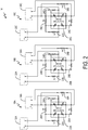
- FIG. 2 is a schematic diagram of aircraft engine pressure transducer 16 for prognostic health monitoring including pressure transducer channel 18A, pressure transducer channel 18B, and pressure transducer channel 18C.
- Pressure transducer channel 18A includes wheatstone bridge 20A; resistors 22A, 24A, 26A, 28A, and 30A; signal output 32A; and excitation input 34A.
- Pressure transducer channel 18B includes wheatstone bridge 20B; resistors 22B, 24B, 26B, 28B, and 30B; output signal 32B; and excitation input 34B.
- Pressure transducer channel 18C includes wheatstone bridge 20C; resistors 22C, 24C, 26C, 28C, and 30C; output signal 32C; and excitation input 34C.
- aircraft engine pressure transducer 16 is discussed with respect to aircraft engine pressure prognostic health monitoring system 10 of FIG. 1 .
- Pressure transducer channels 18A-18C receive a voltage from engine control unit 14 at excitation inputs 34A-34C. Excitation inputs 34A-34C provide the excitation signal to wheatstone bridges 20A-20C. Pressure transducer channels 18A-18C provide a pressure signal corresponding to the pressure sensed by wheatstone bridges 20A-20C from signal outputs 32A-32C.
- Each of wheatstone bridges 20A-20C is mechanically coupled to a glass disk to sense a pressure of aircraft engine 12.
- wheatstone bridges 20A-20C are the same wheatstone bridge such that pressure transducer channels 18A-18C use the same wheatstone bridge.
- the glass disk causes the resistance of each of wheatstone bridges 20A-20C to predictably vary with the pressure of aircraft engine 12.
- each of wheatstone bridges 20A-20C acts as a voltage divider to provide the pressure signal.
- Each of wheatstone bridges 20A-20C is electrically coupled to a separate resistor network comprised of five resistors.
- Each of resistors 22A-22CC, 24A-24C, 26A-26C, 28A-28C, and 30A-30C can comprise an individual resistor, multiple resistors, and/or other electrical components designed to achieve a desired resistance.
- the individual sensors of each resistor network provide a zero offset, a zero offset temperature compensation, and a span temperature compensation according to the table below:
- Pressure transducer channels 18A and 18B are redundant pressure transducer channels. Pressure transducer channels 18A and 18B are redundant in order to meet aircraft regulation specifications. The resistors corresponding to the same offset and/or compensation are the same nominal value in pressure transducer channels 18A and 18B. This gives channels 18A and 18B the same zero offset, the same zero offset temperature compensation, and the same span temperature compensation. Pressure transducer channel 18C is configured to provide a zero offset, a zero offset temperature compensation, and a span temperature compensation that is different from channels 18A and 18B. More specifically, pressure transducer channel 18C provides a higher zero offset and a lower full scale output over a smaller temperature range.
- channels 18A and 18B are configured to have a zero offset output of 5mV at 1.5 absolute pounds per square inch (PSIA) and a full scale output of 50 mV at 63 PSIA over a temperature range of -55°C to 177°C (-67°F to 350°F).
- a typical pressure transducer channel is ⁇ 3% full scale accurate, which results in an accuracy of ⁇ 2 PSIA.
- Channel 18C is configured to have a zero offset output of 5mV at 8 PSIA and a full scale output of 50mV at 24 PSIA over a temperature range of 27°C to 138°C (80°F to 280°F).
- channel 18C is designed to ⁇ 3% accuracy, which gives channel 18C an accuracy of ⁇ 0.5 PSIA.
- channel 18C is designed to ⁇ 1% accuracy, which gives channel 18C an accuracy of ⁇ 0.2 PSIA.
- more accurate aircraft engine pressure sensing can be accomplished without losing the full range of aircraft engine pressure sensing.
- Using a third pressure transducer channel configured to operate over a narrow pressure and temperature span improves the accuracy of aircraft engine pressure sensing within a range of interest. This improves prognostic health monitoring of aircraft engines by providing more accurate data within the range of interest, allowing trend data to have a smaller tolerance and making data aberrations more obvious.
- An aircraft engine pressure transducer can comprise a first pressure transducer channel configured to sense a pressure of the aircraft engine over a first pressure range and a first temperature range; and a second pressure transducer channel configured to sense the pressure of the aircraft engine over a second pressure range and a second temperature range, the second pressure range being a subset of the first temperature range, and the second temperature range being a subset of the first temperature range.
- a third pressure transducer channel can be configured to sense the pressure of the aircraft engine over the first pressure range and the first temperature range.
- the first pressure transducer channel can comprise a first wheatstone bridge configured to change resistance based upon the pressure of the aircraft engine; and the second pressure transducer channel can comprise a second wheatstone bridge configured to change resistance based upon the pressure of the aircraft engine; and the third pressure transducer channel can comprise a third wheatstone bridge configured to change resistance based upon the pressure of the aircraft engine.
- the first pressure transducer channel can comprise a first resistor network electrically coupled to the first wheatstone bridge; the second pressure transducer channel can comprise a second resistor network electrically coupled to the second wheatstone bridge; and the third pressure transducer channel can comprise a third resistor network electrically coupled to the third wheatstone bridge.
- the first resistor network can be configured to provide a first pressure zero offset, a first zero offset temperature compensation and a first pressure span temperature compensation to provide the first pressure range and the first temperature range;
- the second resistor network can be configured to provide a second pressure zero offset, a second zero offset temperature compensation and a second pressure span temperature compensation to provide the second pressure range and the second temperature range;
- the third resistor network can be configured to provide the first pressure zero offset, the first zero offset temperature compensation and the first pressure span temperature compensation to provide the first pressure range and the first temperature range.
- Resistor values of the first resistor network can be nominally equal to resistors of the third resistor network.
- the first, second, and third pressure transducer channels can be electrically coupled to a single wheatstone bridge.
- the first pressure transducer channel can comprise a first resistor network electrically coupled to the single wheatstone bridge; the second pressure transducer channel can comprise a second resistor network electrically coupled to the single wheatstone bridge; and the third pressure transducer channel can comprise a third resistor network electrically coupled to the single wheatstone bridge.
- the first resistor network can be configured to provide a first pressure zero offset, a first zero offset temperature compensation and a first pressure span temperature compensation to provide the first pressure range and the first temperature range;
- the second resistor network can be configured to provide a second pressure zero offset, a second zero offset temperature compensation and a second pressure span temperature compensation to provide the second pressure range and the second temperature range;
- the third resistor network can be configured to provide the first pressure zero offset, the first zero offset temperature compensation and the first pressure span temperature compensation to provide the first pressure range and the first temperature range.
- the second pressure range can be less than one half of the first pressure range; and the second temperature range can be less than one half of the first temperature range.
- a system can comprise an aircraft engine; an engine control unit; and an aircraft engine pressure transducer communicatively coupled to the engine control unit, the aircraft engine pressure transducer configured to sense a pressure of the aircraft engine, the aircraft engine pressure transducer comprises a first pressure transducer channel configured to sense the pressure of the aircraft engine over a first pressure range and a first temperature range; a second pressure transducer channel configured to sense the pressure of the aircraft engine over the first pressure range and the first temperature range; and a third pressure transducer channel configured to sense the pressure of the aircraft engine over a second pressure range and a second temperature range, the second pressure range being a subset of the first temperature range, and the second temperature range being a subset of the first temperature range.
- the system of the preceding paragraph can optionally include, additionally and/or alternatively, any one or more of the following features, configurations and/or additional components:
- the first pressure transducer channel can comprise a first wheatstone bridge configured to change resistance based upon the pressure of the aircraft engine; and the second pressure transducer channel can comprise a second wheatstone bridge configured to change resistance based upon the pressure of the aircraft engine; and the third pressure transducer channel can comprise a third wheatstone bridge configured to change resistance based upon the pressure of the aircraft engine.
- the first pressure transducer channel can comprise a first resistor network electrically coupled to the first wheatstone bridge; the second pressure transducer channel can comprise a second resistor network electrically coupled to the second wheatstone bridge; and the third pressure transducer channel can comprise a third resistor network electrically coupled to the third wheatstone bridge.
- the first resistor network can be configured to provide a first pressure zero offset, a first zero offset temperature compensation and a first pressure span temperature compensation to provide the first pressure range and the first temperature range;
- the second resistor network can be configured to provide the first pressure zero offset, the first zero offset temperature compensation and the first pressure span temperature compensation to provide the first pressure range and the first temperature range;
- the third resistor network can be configured to provide a second pressure zero offset, a second zero offset temperature compensation and a second pressure span temperature compensation to provide the second pressure range and the second temperature range.
- Resistor values of the first resistor network can be nominally equal to resistors of the second resistor network.
- the first, second, and third pressure transducer channels can be electrically coupled to a single wheatstone bridge.
- the first pressure transducer channel can comprise a first resistor network electrically coupled to the single wheatstone bridge; the second pressure transducer channel can comprise a second resistor network electrically coupled to the single wheatstone bridge; and the third pressure transducer channel can comprise a third resistor network electrically coupled to the single wheatstone bridge.
- the first resistor network can be configured to provide a first pressure zero offset, a first zero offset temperature compensation and a first pressure span temperature compensation to provide the first pressure range and the first temperature range;
- the second resistor network can be configured to provide the first pressure zero offset, the first zero offset temperature compensation and the first pressure span temperature compensation to provide the first pressure range and the first temperature range;
- the third resistor network can be configured to provide a second pressure zero offset, a second zero offset temperature compensation and a second pressure span temperature compensation to provide the second pressure range and the second temperature range.
- the first pressure transducer channel can comprise a first excitation input configured to receive a first excitation signal from the engine control unit; and a first pressure signal output configured to provide, to the engine control unit, a first pressure signal based upon the aircraft engine pressure and the first excitation signal;
- the second pressure transducer channel can comprise a second excitation input configured to receive a second excitation signal from the engine control unit; and a second pressure signal output configured to provide, to the engine control unit, a second pressure signal based upon the aircraft engine pressure and the second excitation signal;
- the third pressure transducer channel can comprise a third excitation input configured to receive a third excitation signal from the engine control unit; and a third pressure signal output configured to provide, to the engine control unit, a third pressure signal based upon the aircraft engine pressure and the third excitation signal.
- the second pressure range can be less than one half of the first pressure range; and the second temperature range can be less than one half of the first temperature range.
Landscapes
- Physics & Mathematics (AREA)
- General Physics & Mathematics (AREA)
- Chemical & Material Sciences (AREA)
- Engineering & Computer Science (AREA)
- Combustion & Propulsion (AREA)
- Measuring Fluid Pressure (AREA)
Abstract
Description
- Aircraft engine pressure transducers are typically designed to operate over the full range of pressure and temperature of aircraft engines. This limits the accuracy of aircraft engine pressure transducers because the full pressure range is scaled against the transducer electrical output range. The temperature compensation resistors are also scaled against the full possible temperature range, further limiting the accuracy of aircraft engine pressure transducers. This arrangement provides an accuracy that can be insufficient for prognostic health monitoring.
- In one example, an aircraft engine pressure transducer comprises a first pressure transducer channel and a second pressure transducer channel. The first pressure transducer channel is configured to sense a pressure of the aircraft engine over a first pressure range and a first temperature range. The second pressure transducer channel is configured to sense the pressure of the aircraft engine over a second pressure range and a second temperature range, the second pressure range being a subset of the first temperature range, and the second temperature range being a subset of the first temperature range.
- In one example, a system comprises an aircraft engine, an engine control unit, and an aircraft engine pressure transducer. The aircraft engine pressure transducer is communicatively coupled to the engine control unit. The aircraft engine pressure transducer is configured to sense a pressure of the aircraft engine. The aircraft engine pressure transducer comprises a first pressure transducer channel, a second pressure transducer channel, and a third pressure transducer channel. The first pressure transducer channel is configured to sense the pressure of the aircraft engine over a first pressure range and a first temperature range. The second pressure transducer channel is configured to sense the pressure of the aircraft engine over the first pressure range and the first temperature range. The third pressure transducer channel is configured to sense the pressure of the aircraft engine over a second pressure range and a second temperature range, the second pressure range being a subset of the first temperature range, and the second temperature range being a subset of the first temperature range.
-
-
FIG. 1 is a schematic diagram of an aircraft engine three-channel prognostic health monitoring pressure transducer. -
FIG. 2 is a block diagram of an aircraft engine pressure prognostic health monitoring system. - Apparatus, systems, and associated methods relate to aircraft engine pressure transducers. Using the apparatus, systems, and associated methods herein, an additional pressure transducer channel with a narrower pressure and temperature range than existing pressure transducer channels is added to aircraft engine pressure transducers. This allows for more accurate pressure monitoring of aircraft engines without losing the ability to monitor the full pressure over the full temperature range of an aircraft engine. Moreover, the additional pressure transducer channel can be added to existing aircraft engine pressure transducers without increasing the size of the aircraft engine pressure transducer.
-
FIG. 1 is a block diagram of aircraft engine pressure prognostichealth monitoring system 10 includingaircraft engine 12 andengine control unit 14.Aircraft engine 12 includes aircraftengine pressure transducer 16. Aircraft engine pressure transducer includespressure transducer channels 18A-18C. -
Pressure transducer channels 18A-18C each receive an excitation signal fromengine control unit 14. The excitation signal is a predetermined voltage.Pressure transducer channels 18A-18C provide a pressure signal toengine control unit 14 that varies based upon a pressure ofaircraft engine 12. The pressure signal is a voltage that corresponds to the pressure sensed by each ofpressure transducer channels 18A-18C. -
FIG. 2 is a schematic diagram of aircraftengine pressure transducer 16 for prognostic health monitoring includingpressure transducer channel 18A,pressure transducer channel 18B, andpressure transducer channel 18C.Pressure transducer channel 18A includeswheatstone bridge 20A;resistors signal output 32A; andexcitation input 34A.Pressure transducer channel 18B includeswheatstone bridge 20B;resistors Pressure transducer channel 18C includeswheatstone bridge 20C;resistors output signal 32C; andexcitation input 34C. For purposes of clarity and ease of discussion, aircraftengine pressure transducer 16 is discussed with respect to aircraft engine pressure prognostichealth monitoring system 10 ofFIG. 1 . -
Pressure transducer channels 18A-18C receive a voltage fromengine control unit 14 atexcitation inputs 34A-34C.Excitation inputs 34A-34C provide the excitation signal towheatstone bridges 20A-20C.Pressure transducer channels 18A-18C provide a pressure signal corresponding to the pressure sensed bywheatstone bridges 20A-20C fromsignal outputs 32A-32C. Each ofwheatstone bridges 20A-20C is mechanically coupled to a glass disk to sense a pressure ofaircraft engine 12. In one example,wheatstone bridges 20A-20C are the same wheatstone bridge such thatpressure transducer channels 18A-18C use the same wheatstone bridge. The glass disk causes the resistance of each ofwheatstone bridges 20A-20C to predictably vary with the pressure ofaircraft engine 12. The resistance of each ofwheatstone bridges 20A-20C acts as a voltage divider to provide the pressure signal. Each ofwheatstone bridges 20A-20C is electrically coupled to a separate resistor network comprised of five resistors. Each ofresistors 22A-22CC, 24A-24C, 26A-26C, 28A-28C, and 30A-30C can comprise an individual resistor, multiple resistors, and/or other electrical components designed to achieve a desired resistance. The individual sensors of each resistor network provide a zero offset, a zero offset temperature compensation, and a span temperature compensation according to the table below: - 22A-22C = zero offset temperature compensation resistors
- 24A-24C = zero offset temperature compensation resistors
- 26A-26C = zero offset resistors
- 28A-28C = zero offset resistors
- 30A-30C = span temperature compensation resistors
-
Pressure transducer channels Pressure transducer channels pressure transducer channels channels Pressure transducer channel 18C is configured to provide a zero offset, a zero offset temperature compensation, and a span temperature compensation that is different fromchannels pressure transducer channel 18C provides a higher zero offset and a lower full scale output over a smaller temperature range. - In one example,
channels channel 18C is designed to ±3% accuracy, which giveschannel 18C an accuracy of ±0.5 PSIA. The narrower range of resistor values used for the narrower pressure and temperature ranges allow for designing more accurate pressure transducer channels due to the tolerance of the resistors. In another example,channel 18C is designed to ±1% accuracy, which giveschannel 18C an accuracy of ±0.2 PSIA. - Accordingly, implementing techniques of this disclosure, more accurate aircraft engine pressure sensing can be accomplished without losing the full range of aircraft engine pressure sensing. Using a third pressure transducer channel configured to operate over a narrow pressure and temperature span improves the accuracy of aircraft engine pressure sensing within a range of interest. This improves prognostic health monitoring of aircraft engines by providing more accurate data within the range of interest, allowing trend data to have a smaller tolerance and making data aberrations more obvious.
- The following are non-exclusive descriptions of possible embodiments of the present invention.
- An aircraft engine pressure transducer can comprise a first pressure transducer channel configured to sense a pressure of the aircraft engine over a first pressure range and a first temperature range; and a second pressure transducer channel configured to sense the pressure of the aircraft engine over a second pressure range and a second temperature range, the second pressure range being a subset of the first temperature range, and the second temperature range being a subset of the first temperature range.
- The aircraft engine pressure transducer of the preceding paragraph can optionally include, additionally and/or alternatively, any one or more of the following features, configurations and/or additional components:
A third pressure transducer channel can be configured to sense the pressure of the aircraft engine over the first pressure range and the first temperature range. - The first pressure transducer channel can comprise a first wheatstone bridge configured to change resistance based upon the pressure of the aircraft engine; and the second pressure transducer channel can comprise a second wheatstone bridge configured to change resistance based upon the pressure of the aircraft engine; and the third pressure transducer channel can comprise a third wheatstone bridge configured to change resistance based upon the pressure of the aircraft engine.
- The first pressure transducer channel can comprise a first resistor network electrically coupled to the first wheatstone bridge; the second pressure transducer channel can comprise a second resistor network electrically coupled to the second wheatstone bridge; and the third pressure transducer channel can comprise a third resistor network electrically coupled to the third wheatstone bridge.
- The first resistor network can be configured to provide a first pressure zero offset, a first zero offset temperature compensation and a first pressure span temperature compensation to provide the first pressure range and the first temperature range; the second resistor network can be configured to provide a second pressure zero offset, a second zero offset temperature compensation and a second pressure span temperature compensation to provide the second pressure range and the second temperature range; and the third resistor network can be configured to provide the first pressure zero offset, the first zero offset temperature compensation and the first pressure span temperature compensation to provide the first pressure range and the first temperature range.
- Resistor values of the first resistor network can be nominally equal to resistors of the third resistor network.
- The first, second, and third pressure transducer channels can be electrically coupled to a single wheatstone bridge.
- The first pressure transducer channel can comprise a first resistor network electrically coupled to the single wheatstone bridge; the second pressure transducer channel can comprise a second resistor network electrically coupled to the single wheatstone bridge; and the third pressure transducer channel can comprise a third resistor network electrically coupled to the single wheatstone bridge.
- The first resistor network can be configured to provide a first pressure zero offset, a first zero offset temperature compensation and a first pressure span temperature compensation to provide the first pressure range and the first temperature range; the second resistor network can be configured to provide a second pressure zero offset, a second zero offset temperature compensation and a second pressure span temperature compensation to provide the second pressure range and the second temperature range; and the third resistor network can be configured to provide the first pressure zero offset, the first zero offset temperature compensation and the first pressure span temperature compensation to provide the first pressure range and the first temperature range.
- The second pressure range can be less than one half of the first pressure range; and the second temperature range can be less than one half of the first temperature range.
- A system can comprise an aircraft engine; an engine control unit; and an aircraft engine pressure transducer communicatively coupled to the engine control unit, the aircraft engine pressure transducer configured to sense a pressure of the aircraft engine, the aircraft engine pressure transducer comprises a first pressure transducer channel configured to sense the pressure of the aircraft engine over a first pressure range and a first temperature range; a second pressure transducer channel configured to sense the pressure of the aircraft engine over the first pressure range and the first temperature range; and a third pressure transducer channel configured to sense the pressure of the aircraft engine over a second pressure range and a second temperature range, the second pressure range being a subset of the first temperature range, and the second temperature range being a subset of the first temperature range.
- The system of the preceding paragraph can optionally include, additionally and/or alternatively, any one or more of the following features, configurations and/or additional components:
The first pressure transducer channel can comprise a first wheatstone bridge configured to change resistance based upon the pressure of the aircraft engine; and the second pressure transducer channel can comprise a second wheatstone bridge configured to change resistance based upon the pressure of the aircraft engine; and the third pressure transducer channel can comprise a third wheatstone bridge configured to change resistance based upon the pressure of the aircraft engine. - The first pressure transducer channel can comprise a first resistor network electrically coupled to the first wheatstone bridge; the second pressure transducer channel can comprise a second resistor network electrically coupled to the second wheatstone bridge; and the third pressure transducer channel can comprise a third resistor network electrically coupled to the third wheatstone bridge.
- The first resistor network can be configured to provide a first pressure zero offset, a first zero offset temperature compensation and a first pressure span temperature compensation to provide the first pressure range and the first temperature range; the second resistor network can be configured to provide the first pressure zero offset, the first zero offset temperature compensation and the first pressure span temperature compensation to provide the first pressure range and the first temperature range; and the third resistor network can be configured to provide a second pressure zero offset, a second zero offset temperature compensation and a second pressure span temperature compensation to provide the second pressure range and the second temperature range.
- Resistor values of the first resistor network can be nominally equal to resistors of the second resistor network.
- The first, second, and third pressure transducer channels can be electrically coupled to a single wheatstone bridge.
- The first pressure transducer channel can comprise a first resistor network electrically coupled to the single wheatstone bridge; the second pressure transducer channel can comprise a second resistor network electrically coupled to the single wheatstone bridge; and the third pressure transducer channel can comprise a third resistor network electrically coupled to the single wheatstone bridge.
- The first resistor network can be configured to provide a first pressure zero offset, a first zero offset temperature compensation and a first pressure span temperature compensation to provide the first pressure range and the first temperature range; the second resistor network can be configured to provide the first pressure zero offset, the first zero offset temperature compensation and the first pressure span temperature compensation to provide the first pressure range and the first temperature range; and the third resistor network can be configured to provide a second pressure zero offset, a second zero offset temperature compensation and a second pressure span temperature compensation to provide the second pressure range and the second temperature range.
- The first pressure transducer channel can comprise a first excitation input configured to receive a first excitation signal from the engine control unit; and a first pressure signal output configured to provide, to the engine control unit, a first pressure signal based upon the aircraft engine pressure and the first excitation signal; the second pressure transducer channel can comprise a second excitation input configured to receive a second excitation signal from the engine control unit; and a second pressure signal output configured to provide, to the engine control unit, a second pressure signal based upon the aircraft engine pressure and the second excitation signal; the third pressure transducer channel can comprise a third excitation input configured to receive a third excitation signal from the engine control unit; and a third pressure signal output configured to provide, to the engine control unit, a third pressure signal based upon the aircraft engine pressure and the third excitation signal.
- The second pressure range can be less than one half of the first pressure range; and the second temperature range can be less than one half of the first temperature range.
- While the invention has been described with reference to an exemplary embodiment(s), it will be understood by those skilled in the art that various changes may be made and equivalents may be substituted for elements thereof without departing from the scope of the invention as defined by the claims. In addition, many modifications may be made to adapt a particular situation or material to the teachings of the invention without departing from the scope thereof. Therefore, it is intended that the invention not be limited to the particular embodiment(s) disclosed, but that the invention will include all embodiments falling within the scope of the appended claims.
Claims (12)
- An aircraft engine pressure transducer comprising:a first pressure transducer channel (18A) configured to sense a pressure of the aircraft engine over a first pressure range and a first temperature range; anda second pressure transducer channel (18B) configured to sense the pressure of the aircraft engine over a second pressure range and a second temperature range, the second pressure range being a subset of the first temperature range, and the second temperature range being a subset of the first temperature range.
- The aircraft engine pressure transducer of claim 1, further comprising a third pressure transducer channel (18C) configured to sense the pressure of the aircraft engine over the first pressure range and the first temperature range.
- The aircraft engine pressure transducer of claim 2, wherein:the first pressure transducer channel comprises a first wheatstone bridge (20A) configured to change resistance based upon the pressure of the aircraft engine; andthe second pressure transducer channel comprises a second wheatstone bridge (20B) configured to change resistance based upon the pressure of the aircraft engine; andthe third pressure transducer channel comprises a third wheatstone bridge (20C) configured to change resistance based upon the pressure of the aircraft engine.
- The aircraft engine pressure transducer of claim 3, wherein:the first pressure transducer channel further comprises a first resistor network electrically coupled to the first wheatstone bridge;the second pressure transducer channel further comprises a second resistor network electrically coupled to the second wheatstone bridge; andthe third pressure transducer channel further comprises a third resistor network electrically coupled to the third wheatstone bridge.
- The aircraft engine pressure transducer of claim 4, wherein:the first resistor network is configured to provide a first pressure zero offset, a first zero offset temperature compensation and a first pressure span temperature compensation to provide the first pressure range and the first temperature range;the second resistor network is configured to provide a second pressure zero offset, a second zero offset temperature compensation and a second pressure span temperature compensation to provide the second pressure range and the second temperature range; andthe third resistor network is configured to provide the first pressure zero offset, the first zero offset temperature compensation and the first pressure span temperature compensation to provide the first pressure range and the first temperature range.
- The aircraft engine pressure transducer of claim 3 or any claim dependent thereon, wherein resistor values of the first resistor network are nominally equal to resistors of the third resistor network.
- The aircraft engine pressure transducer of claim 2, wherein the first, second, and third pressure transducer channels are electrically coupled to a single wheatstone bridge.
- The aircraft engine pressure transducer of claim 7, wherein:the first pressure transducer channel further comprises a first resistor network electrically coupled to the single wheatstone bridge;the second pressure transducer channel further comprises a second resistor network electrically coupled to the single wheatstone bridge; andthe third pressure transducer channel further comprises a third resistor network electrically coupled to the single wheatstone bridge.
- The aircraft engine pressure transducer of claim 8, wherein:the first resistor network is configured to provide a first pressure zero offset, a first zero offset temperature compensation and a first pressure span temperature compensation to provide the first pressure range and the first temperature range;the second resistor network is configured to provide a second pressure zero offset, a second zero offset temperature compensation and a second pressure span temperature compensation to provide the second pressure range and the second temperature range; andthe third resistor network is configured to provide the first pressure zero offset, the first zero offset temperature compensation and the first pressure span temperature compensation to provide the first pressure range and the first temperature range.
- The aircraft engine pressure transducer of any preceding claim, wherein:the second pressure range is less than one half of the first pressure range; andthe second temperature range is less than one half of the first temperature range.
- A system comprising:an aircraft engine (12);an engine control unit (14); andan aircraft engine pressure transducer (16) as claimed in claim 2 or any claim dependent thereon, communicatively coupled to the engine control unit, the aircraft engine pressure transducer configured to sense a pressure of the aircraft engine.
- The aircraft engine pressure transducer of claim 11, wherein:the first pressure transducer channel comprises:a first excitation input (34A) configured to receive a first excitation signal from the engine control unit; anda first pressure signal output (32A) configured to provide, to the engine control unit, a first pressure signal based upon the aircraft engine pressure and the first excitation signal;the second pressure transducer channel comprises:a second excitation input (34B) configured to receive a second excitation signal from the engine control unit; anda second pressure signal output (32B) configured to provide, to the engine control unit, a second pressure signal based upon the aircraft engine pressure and the second excitation signal;the third pressure transducer channel comprises:a third excitation input (34C) configured to receive a third excitation signal from the engine control unit; anda third pressure signal output (32C) configured to provide, to the engine control unit, a third pressure signal based upon the aircraft engine pressure and the third excitation signal.
Applications Claiming Priority (1)
| Application Number | Priority Date | Filing Date | Title |
|---|---|---|---|
| US15/941,156 US10718678B2 (en) | 2018-03-30 | 2018-03-30 | Aircraft engine multi-channel pressure transducer |
Publications (1)
| Publication Number | Publication Date |
|---|---|
| EP3546912A1 true EP3546912A1 (en) | 2019-10-02 |
Family
ID=66041195
Family Applications (1)
| Application Number | Title | Priority Date | Filing Date |
|---|---|---|---|
| EP19166153.7A Ceased EP3546912A1 (en) | 2018-03-30 | 2019-03-29 | Prognostic health monitoring pressure transducer |
Country Status (2)
| Country | Link |
|---|---|
| US (1) | US10718678B2 (en) |
| EP (1) | EP3546912A1 (en) |
Families Citing this family (1)
| Publication number | Priority date | Publication date | Assignee | Title |
|---|---|---|---|---|
| US11415472B2 (en) | 2020-06-10 | 2022-08-16 | Harcosemco Llc | Flexible bridge sensor electronic architecture and method for implementing same |
Citations (5)
| Publication number | Priority date | Publication date | Assignee | Title |
|---|---|---|---|---|
| US20100083764A1 (en) * | 2008-10-02 | 2010-04-08 | Kulite Semiconductor Products, Inc. | Redundant self compensating leadless pressure sensor |
| US20110179879A1 (en) * | 2008-12-19 | 2011-07-28 | Honeywell International Inc. | Multi range pressure sensor apparatus and method utilizing a single sense die and multiple signal paths |
| US20130055821A1 (en) * | 2011-09-06 | 2013-03-07 | Honeywell International Inc. | Packaged sensor with multiple sensors elements |
| US20150107367A1 (en) * | 2013-10-21 | 2015-04-23 | Continental Automotive Systems, Inc. | Dual range high precision pressure sensor |
| US20170343443A1 (en) * | 2016-05-24 | 2017-11-30 | Kulite Semiconductor Products, Inc. | Systems and methods for switched multi-transducer pressure sensors and compensation thereof |
Family Cites Families (4)
| Publication number | Priority date | Publication date | Assignee | Title |
|---|---|---|---|---|
| US5116331A (en) * | 1991-04-23 | 1992-05-26 | The United States Of America As Represented By The Administrator Of The National Aeronautics And Space Administration | Pressure transducer and system for cryogenic environments |
| US9354132B2 (en) | 2009-02-12 | 2016-05-31 | Continental Automotive Systems, Inc. | Jointless pressure sensor port |
| RU2585486C1 (en) | 2015-04-07 | 2016-05-27 | Федеральное государственное автономное образовательное учреждение высшего образования "Национальный исследовательский университет "Московский институт электронной техники" (МИЭТ) | Method of measuring pressure and calibration based on tensobridge integrated pressure transducer |
| US10764083B2 (en) | 2016-07-25 | 2020-09-01 | Fisher-Rosemount Systems, Inc. | Portable field maintenance tool with resistor network for intrinsically safe operation |
-
2018
- 2018-03-30 US US15/941,156 patent/US10718678B2/en active Active
-
2019
- 2019-03-29 EP EP19166153.7A patent/EP3546912A1/en not_active Ceased
Patent Citations (5)
| Publication number | Priority date | Publication date | Assignee | Title |
|---|---|---|---|---|
| US20100083764A1 (en) * | 2008-10-02 | 2010-04-08 | Kulite Semiconductor Products, Inc. | Redundant self compensating leadless pressure sensor |
| US20110179879A1 (en) * | 2008-12-19 | 2011-07-28 | Honeywell International Inc. | Multi range pressure sensor apparatus and method utilizing a single sense die and multiple signal paths |
| US20130055821A1 (en) * | 2011-09-06 | 2013-03-07 | Honeywell International Inc. | Packaged sensor with multiple sensors elements |
| US20150107367A1 (en) * | 2013-10-21 | 2015-04-23 | Continental Automotive Systems, Inc. | Dual range high precision pressure sensor |
| US20170343443A1 (en) * | 2016-05-24 | 2017-11-30 | Kulite Semiconductor Products, Inc. | Systems and methods for switched multi-transducer pressure sensors and compensation thereof |
Also Published As
| Publication number | Publication date |
|---|---|
| US10718678B2 (en) | 2020-07-21 |
| US20190301955A1 (en) | 2019-10-03 |
Similar Documents
| Publication | Publication Date | Title |
|---|---|---|
| AU2008261367B2 (en) | Operation method and switch arrangement for a capacitive micromechanical sensor with analog reset | |
| US4468968A (en) | Method and arrangement for providing information to define the values of a set of parameters which characterize an element | |
| CN105306056B (en) | A Scale Factor Temperature Compensation Method for Current-Frequency Conversion Circuit | |
| EP0533389A2 (en) | Amplified pressure transducer | |
| EP2924405B1 (en) | Intake air temperature sensor and flow measurement device | |
| US20050028588A1 (en) | Method and device for measuring humidity | |
| US6035721A (en) | Process for compensating for the incorrect operation of measuring devices caused by external influences | |
| US20160231187A1 (en) | Pressure Transducer | |
| US10274392B2 (en) | Control system, pressure detection system, methods and programs therefor | |
| US10359321B2 (en) | On-chip circuit and method for accurately measuring die temperature of an integrated circuit | |
| US6910804B2 (en) | Resistive temperature device (RTD) module with improved noise immunity | |
| EP4165382A1 (en) | Flexible bridge sensor electronic architecture and method for implementing same | |
| US5534773A (en) | Method for compensating an offset voltage temperature drift in a semiconductor strain gage sensor | |
| US10718678B2 (en) | Aircraft engine multi-channel pressure transducer | |
| US7088108B2 (en) | Method for detecting an offset drift in a wheatstone measuring bridge | |
| RU2571445C2 (en) | Correction of voltage measurement at transducer terminals | |
| EP2745284B1 (en) | Two-wire process control loop current diagnostics | |
| US8893554B2 (en) | System and method for passively compensating pressure sensors | |
| US20190064198A1 (en) | Air data system architectures using integrated pressure probes | |
| US10101290B2 (en) | Method for determining the conductivity of a medium | |
| US20160349132A1 (en) | Physical quantity detector | |
| KR101306407B1 (en) | Temperature measuring method using piezoresistive pressure sensor and temperature measuring device | |
| EP4269968A1 (en) | High accuracy computational method in resistance temperature detector measurements | |
| JPH01227030A (en) | Detecting circuit of resistance temperature characteristic | |
| US3717038A (en) | Direct current pressure ratio circuit |
Legal Events
| Date | Code | Title | Description |
|---|---|---|---|
| PUAI | Public reference made under article 153(3) epc to a published international application that has entered the european phase |
Free format text: ORIGINAL CODE: 0009012 |
|
| STAA | Information on the status of an ep patent application or granted ep patent |
Free format text: STATUS: THE APPLICATION HAS BEEN PUBLISHED |
|
| AK | Designated contracting states |
Kind code of ref document: A1 Designated state(s): AL AT BE BG CH CY CZ DE DK EE ES FI FR GB GR HR HU IE IS IT LI LT LU LV MC MK MT NL NO PL PT RO RS SE SI SK SM TR |
|
| AX | Request for extension of the european patent |
Extension state: BA ME |
|
| RIN1 | Information on inventor provided before grant (corrected) |
Inventor name: PARADISE, BRUCE |
|
| STAA | Information on the status of an ep patent application or granted ep patent |
Free format text: STATUS: REQUEST FOR EXAMINATION WAS MADE |
|
| 17P | Request for examination filed |
Effective date: 20191121 |
|
| RBV | Designated contracting states (corrected) |
Designated state(s): AL AT BE BG CH CY CZ DE DK EE ES FI FR GB GR HR HU IE IS IT LI LT LU LV MC MK MT NL NO PL PT RO RS SE SI SK SM TR |
|
| STAA | Information on the status of an ep patent application or granted ep patent |
Free format text: STATUS: EXAMINATION IS IN PROGRESS |
|
| 17Q | First examination report despatched |
Effective date: 20200730 |
|
| STAA | Information on the status of an ep patent application or granted ep patent |
Free format text: STATUS: THE APPLICATION HAS BEEN REFUSED |
|
| 18R | Application refused |
Effective date: 20211008 |