EP3546797A1 - Drive axle locking device, power drive system, and vehicle - Google Patents
Drive axle locking device, power drive system, and vehicle Download PDFInfo
- Publication number
- EP3546797A1 EP3546797A1 EP17887429.3A EP17887429A EP3546797A1 EP 3546797 A1 EP3546797 A1 EP 3546797A1 EP 17887429 A EP17887429 A EP 17887429A EP 3546797 A1 EP3546797 A1 EP 3546797A1
- Authority
- EP
- European Patent Office
- Prior art keywords
- drive shaft
- drive
- joint part
- locking device
- vehicle according
- Prior art date
- Legal status (The legal status is an assumption and is not a legal conclusion. Google has not performed a legal analysis and makes no representation as to the accuracy of the status listed.)
- Withdrawn
Links
- 230000007246 mechanism Effects 0.000 claims abstract description 26
- 230000005540 biological transmission Effects 0.000 claims description 21
- 239000000969 carrier Substances 0.000 claims description 8
- 238000010586 diagram Methods 0.000 description 9
- 230000000694 effects Effects 0.000 description 5
- 230000009286 beneficial effect Effects 0.000 description 4
- 230000000875 corresponding effect Effects 0.000 description 4
- 238000013459 approach Methods 0.000 description 3
- 230000002349 favourable effect Effects 0.000 description 3
- 238000000034 method Methods 0.000 description 3
- 230000008569 process Effects 0.000 description 3
- 230000004323 axial length Effects 0.000 description 2
- 239000000463 material Substances 0.000 description 2
- 230000009471 action Effects 0.000 description 1
- 230000008859 change Effects 0.000 description 1
- 238000005516 engineering process Methods 0.000 description 1
- 239000000446 fuel Substances 0.000 description 1
- 239000010687 lubricating oil Substances 0.000 description 1
- 238000004519 manufacturing process Methods 0.000 description 1
- 238000012986 modification Methods 0.000 description 1
- 230000004048 modification Effects 0.000 description 1
- 238000003825 pressing Methods 0.000 description 1
- 230000002035 prolonged effect Effects 0.000 description 1
- 230000009467 reduction Effects 0.000 description 1
Images




Classifications
-
- B—PERFORMING OPERATIONS; TRANSPORTING
- B60—VEHICLES IN GENERAL
- B60B—VEHICLE WHEELS; CASTORS; AXLES FOR WHEELS OR CASTORS; INCREASING WHEEL ADHESION
- B60B35/00—Axle units; Parts thereof ; Arrangements for lubrication of axles
- B60B35/12—Torque-transmitting axles
- B60B35/14—Torque-transmitting axles composite or split, e.g. half- axles; Couplings between axle parts or sections
-
- B—PERFORMING OPERATIONS; TRANSPORTING
- B60—VEHICLES IN GENERAL
- B60K—ARRANGEMENT OR MOUNTING OF PROPULSION UNITS OR OF TRANSMISSIONS IN VEHICLES; ARRANGEMENT OR MOUNTING OF PLURAL DIVERSE PRIME-MOVERS IN VEHICLES; AUXILIARY DRIVES FOR VEHICLES; INSTRUMENTATION OR DASHBOARDS FOR VEHICLES; ARRANGEMENTS IN CONNECTION WITH COOLING, AIR INTAKE, GAS EXHAUST OR FUEL SUPPLY OF PROPULSION UNITS IN VEHICLES
- B60K17/00—Arrangement or mounting of transmissions in vehicles
- B60K17/02—Arrangement or mounting of transmissions in vehicles characterised by arrangement, location, or kind of clutch
-
- B—PERFORMING OPERATIONS; TRANSPORTING
- B60—VEHICLES IN GENERAL
- B60K—ARRANGEMENT OR MOUNTING OF PROPULSION UNITS OR OF TRANSMISSIONS IN VEHICLES; ARRANGEMENT OR MOUNTING OF PLURAL DIVERSE PRIME-MOVERS IN VEHICLES; AUXILIARY DRIVES FOR VEHICLES; INSTRUMENTATION OR DASHBOARDS FOR VEHICLES; ARRANGEMENTS IN CONNECTION WITH COOLING, AIR INTAKE, GAS EXHAUST OR FUEL SUPPLY OF PROPULSION UNITS IN VEHICLES
- B60K17/00—Arrangement or mounting of transmissions in vehicles
- B60K17/04—Arrangement or mounting of transmissions in vehicles characterised by arrangement, location or kind of gearing
-
- B—PERFORMING OPERATIONS; TRANSPORTING
- B60—VEHICLES IN GENERAL
- B60K—ARRANGEMENT OR MOUNTING OF PROPULSION UNITS OR OF TRANSMISSIONS IN VEHICLES; ARRANGEMENT OR MOUNTING OF PLURAL DIVERSE PRIME-MOVERS IN VEHICLES; AUXILIARY DRIVES FOR VEHICLES; INSTRUMENTATION OR DASHBOARDS FOR VEHICLES; ARRANGEMENTS IN CONNECTION WITH COOLING, AIR INTAKE, GAS EXHAUST OR FUEL SUPPLY OF PROPULSION UNITS IN VEHICLES
- B60K17/00—Arrangement or mounting of transmissions in vehicles
- B60K17/04—Arrangement or mounting of transmissions in vehicles characterised by arrangement, location or kind of gearing
- B60K17/043—Transmission unit disposed in on near the vehicle wheel, or between the differential gear unit and the wheel
- B60K17/046—Transmission unit disposed in on near the vehicle wheel, or between the differential gear unit and the wheel with planetary gearing having orbital motion
-
- B—PERFORMING OPERATIONS; TRANSPORTING
- B60—VEHICLES IN GENERAL
- B60K—ARRANGEMENT OR MOUNTING OF PROPULSION UNITS OR OF TRANSMISSIONS IN VEHICLES; ARRANGEMENT OR MOUNTING OF PLURAL DIVERSE PRIME-MOVERS IN VEHICLES; AUXILIARY DRIVES FOR VEHICLES; INSTRUMENTATION OR DASHBOARDS FOR VEHICLES; ARRANGEMENTS IN CONNECTION WITH COOLING, AIR INTAKE, GAS EXHAUST OR FUEL SUPPLY OF PROPULSION UNITS IN VEHICLES
- B60K17/00—Arrangement or mounting of transmissions in vehicles
- B60K17/34—Arrangement or mounting of transmissions in vehicles for driving both front and rear wheels, e.g. four wheel drive vehicles
- B60K17/356—Arrangement or mounting of transmissions in vehicles for driving both front and rear wheels, e.g. four wheel drive vehicles having fluid or electric motor, for driving one or more wheels
-
- B—PERFORMING OPERATIONS; TRANSPORTING
- B60—VEHICLES IN GENERAL
- B60K—ARRANGEMENT OR MOUNTING OF PROPULSION UNITS OR OF TRANSMISSIONS IN VEHICLES; ARRANGEMENT OR MOUNTING OF PLURAL DIVERSE PRIME-MOVERS IN VEHICLES; AUXILIARY DRIVES FOR VEHICLES; INSTRUMENTATION OR DASHBOARDS FOR VEHICLES; ARRANGEMENTS IN CONNECTION WITH COOLING, AIR INTAKE, GAS EXHAUST OR FUEL SUPPLY OF PROPULSION UNITS IN VEHICLES
- B60K7/00—Disposition of motor in, or adjacent to, traction wheel
- B60K7/0007—Disposition of motor in, or adjacent to, traction wheel the motor being electric
-
- B—PERFORMING OPERATIONS; TRANSPORTING
- B62—LAND VEHICLES FOR TRAVELLING OTHERWISE THAN ON RAILS
- B62D—MOTOR VEHICLES; TRAILERS
- B62D11/00—Steering non-deflectable wheels; Steering endless tracks or the like
- B62D11/02—Steering non-deflectable wheels; Steering endless tracks or the like by differentially driving ground-engaging elements on opposite vehicle sides
-
- B—PERFORMING OPERATIONS; TRANSPORTING
- B62—LAND VEHICLES FOR TRAVELLING OTHERWISE THAN ON RAILS
- B62D—MOTOR VEHICLES; TRAILERS
- B62D11/00—Steering non-deflectable wheels; Steering endless tracks or the like
- B62D11/02—Steering non-deflectable wheels; Steering endless tracks or the like by differentially driving ground-engaging elements on opposite vehicle sides
- B62D11/04—Steering non-deflectable wheels; Steering endless tracks or the like by differentially driving ground-engaging elements on opposite vehicle sides by means of separate power sources
-
- F—MECHANICAL ENGINEERING; LIGHTING; HEATING; WEAPONS; BLASTING
- F16—ENGINEERING ELEMENTS AND UNITS; GENERAL MEASURES FOR PRODUCING AND MAINTAINING EFFECTIVE FUNCTIONING OF MACHINES OR INSTALLATIONS; THERMAL INSULATION IN GENERAL
- F16D—COUPLINGS FOR TRANSMITTING ROTATION; CLUTCHES; BRAKES
- F16D11/00—Clutches in which the members have interengaging parts
- F16D11/14—Clutches in which the members have interengaging parts with clutching members movable only axially
-
- F—MECHANICAL ENGINEERING; LIGHTING; HEATING; WEAPONS; BLASTING
- F16—ENGINEERING ELEMENTS AND UNITS; GENERAL MEASURES FOR PRODUCING AND MAINTAINING EFFECTIVE FUNCTIONING OF MACHINES OR INSTALLATIONS; THERMAL INSULATION IN GENERAL
- F16H—GEARING
- F16H1/00—Toothed gearings for conveying rotary motion
- F16H1/28—Toothed gearings for conveying rotary motion with gears having orbital motion
-
- F—MECHANICAL ENGINEERING; LIGHTING; HEATING; WEAPONS; BLASTING
- F16—ENGINEERING ELEMENTS AND UNITS; GENERAL MEASURES FOR PRODUCING AND MAINTAINING EFFECTIVE FUNCTIONING OF MACHINES OR INSTALLATIONS; THERMAL INSULATION IN GENERAL
- F16H—GEARING
- F16H48/00—Differential gearings
- F16H48/20—Arrangements for suppressing or influencing the differential action, e.g. locking devices
- F16H48/30—Arrangements for suppressing or influencing the differential action, e.g. locking devices using externally-actuatable means
- F16H48/34—Arrangements for suppressing or influencing the differential action, e.g. locking devices using externally-actuatable means using electromagnetic or electric actuators
-
- B—PERFORMING OPERATIONS; TRANSPORTING
- B60—VEHICLES IN GENERAL
- B60Y—INDEXING SCHEME RELATING TO ASPECTS CROSS-CUTTING VEHICLE TECHNOLOGY
- B60Y2400/00—Special features of vehicle units
- B60Y2400/70—Gearings
- B60Y2400/73—Planetary gearings
Definitions
- the present invention relates to the technical field of vehicles, and particularly relates to a drive shaft locking device for a vehicle, a power-driven system with the drive shaft locking device, and a vehicle with the power-driven system.
- a new energy vehicle adopts a distributed drive mode. Wheels at two sides are respectively driven by two motors, and the rotation speeds and torques of the left and right wheels can be independently adjusted by a controller respectively, thus canceling a differential mechanism.
- a left half shaft and a right half shaft still need to be locked so as to improve the trafficability. If a traditional electric locking differential mechanism is applied to a distributed-drive new energy vehicle, the differential function of the differential mechanism is wasted. Furthermore, the traditional electric locking differential mechanism has a complicated structure, has more parts and occupies a larger space.
- An objective of the present invention is to at least resolve one of the technical problems in the related art to some extent. Therefore, the present invention provides a drive shaft locking device which is especially suitable for an electric vehicle.
- the drive shaft locking device can lock two drive shafts and is favorable for the vehicle to get rid of the trouble.
- the present invention further provides a power-driven system.
- the present invention further provides a vehicle.
- the drive shaft locking device for the vehicle comprises a planetary gear mechanism, wherein the planetary gear mechanism comprises a sun gear, a planetary gear, a planetary carrier, and a gear ring; a first drive shaft, a second drive shaft, and a power joint device, wherein the power joint device comprises a first joint part and a second joint part, the first drive shaft is connected with one of the sun gear, the planetary carrier and the gear ring, the first drive shaft is further configured to synchronously rotate with the first joint part, the second drive shaft is connected with another one of the sun gear, the planetary carrier and the gear ring, and the second drive shaft is further configured to synchronously rotate with the second joint part; and a joint part drive device, wherein the joint part drive device comprises a drive needle and a drive part, wherein the drive needle is configured to be capable of rotating around the central axis of the sun gear along with the remaining one of the sun gear, the planetary carrier and the gear ring, and be capable of moving along the axial direction
- the drive shaft locking device when the first joint part is jointed with the second joint part, the first drive shaft and the second drive shaft are mutually locked, and the first drive shaft and the second drive shaft can synchronously rotate, thereby being favorable for the vehicle to get rid of the trouble. Furthermore, by means of arrangement of the joint part drive device and the power joint device, the locking of the first drive shaft and the second drive shaft can be realized.
- the drive shaft locking device has the advantages of simple structure, reliable function implementation, few parts, small volume and low cost.
- the drive shaft locking device provided by the present invention can also have the following distinguishing technical features:
- the drive part comprises: a following part, wherein the following part can rotate along with the drive needle, and the following part can be braked; the following part is provided with a drive surface; and when the following part is braked, the drive surface drives the drive needle to move along the axial direction by means of the slide of the drive needle on the drive surface, so that the second joint part is jointed with the first joint part.
- the drive part further comprises: a braking part, wherein the braking part is configured to be used for braking the following part.
- the braking part is configured to brake the following part by means of an electromagnetic force.
- the drive part is an electromagnetic brake
- the following part constitutes a braking component of the electromagnetic brake
- the braking part constitutes a braking frame of the electromagnetic brake.
- the following part hollowly sleeves the first drive shaft.
- the drive surface is an inclined surface or a curved surface.
- the drive surface comprises a first section and a second section, wherein the first section is connected with the second section, the connection part of the first section and the second section is the lowest point, and the other ends of the first section and the second section away from the connection part are the highest points.
- the following part comprises: a following part body and an annular following part flange arranged on the following part body, wherein the end surface of the following part flange facing the drive needle is provided with the drive surface.
- the drive surface is provided with a drive surface limiting groove, and one end of the drive needle is positioned in the drive surface limiting groove.
- the first drive shaft is connected with the sun gear
- the second drive shaft is connected with the gear ring
- the drive needle penetrates through the planetary carrier
- the planetary gear is mounted on the planetary carrier by means of a planetary gear shaft, and the drive needle and the planetary gear shaft are the same component.
- the first drive shaft is connected with the sun gear
- the second drive shaft is connected with the gear ring
- two planetary carriers are provided and are respectively arranged at two sides of the sun gear, and the drive needle penetrates through the two planetary carriers.
- the first drive shaft is connected with the sun gear
- the second drive shaft is connected with the gear ring
- the drive needle penetrates through the planetary carrier
- the drive shaft locking device further comprises: a sleeve, wherein the sleeve is connected between the gear ring and the second drive shaft, and the second joint part rotates along with the sleeve and can move along the axial direction relative to the sleeve.
- the sleeve is provided with a sleeve axial groove
- the second joint part is provided with a second joint part bulge
- the second joint part bulge is arranged in the sleeve axial groove, so that the second joint part can rotate along with the sleeve and can move along the axial direction relative to the sleeve.
- the second joint part hollowly sleeves the first drive shaft.
- the first joint part and the second joint part are both contained in the sleeve.
- the drive shaft locking device further comprises: elastic devices, wherein the elastic devices elastically press against the second joint part so as to enable the second joint part to have the trend of moving towards the direction away from the first joint part.
- the end surface of the first drive shaft close to the second drive shaft is provided with a first drive shaft flange, the first drive shaft flange is opposite to the second joint part, and the elastic devices elastically press between the first drive shaft flange and the second joint part.
- the elastic devices are spiral springs and sleeve the first drive shaft.
- the first joint part sleeves and is fixed on the first drive shaft, and the spiral springs are positioned at the outer side of the first joint part.
- the elastic devices are contained in the sleeve.
- the first joint part is provided with a plurality of first joint teeth distributed along the circumferential direction
- the second joint part is provided with a plurality of second joint teeth distributed along the circumferential direction.
- the second joint part is provided with a second joint part limiting groove, and one end of the drive needle is positioned in the second joint part limiting groove.
- the gear ring has an integrally-formed annular extension part, and the annular extension part constitutes the sleeve.
- a plurality of arc-shaped connecting strips is arranged between the gear ring and the sleeve, and the plurality of arc-shaped connecting strips is distributed at intervals along the circumferential direction and is respectively welded and fixed with the gear ring and the sleeve.
- the first drive shaft is connected with the sun gear
- the second drive shaft is connected with the gear ring
- the drive needle penetrates through the planetary carrier
- the planetary carrier is provided with a plurality of convex plates which is distributed at intervals along the circumferential direction, the plurality of convex plates is divided into first convex plates and second convex plates, the plurality of first convex plates and the plurality of second convex plates are staggered in the circumferential direction, the first convex plates are used for mounting the planetary gear shaft, and the second convex plates are provided with drive needle support holes for supporting the drive needle.
- the first drive shaft is connected with the planetary carrier
- the second drive shaft is connected with the sun gear
- the gear ring is provided with a drive needle axial groove
- the drive needle is slidably arranged in the drive needle axial groove.
- the first drive shaft is connected with the planetary carrier
- the second drive shaft is connected with the gear ring
- the drive needle penetrates through the sun gear and can rotate along with the sun gear around the central axis of the sun gear
- the planetary carrier encircles the electromagnetic brake.
- the power-driven system comprises: the drive shaft locking device for the vehicle; a first motor generator, wherein the first motor generator is in transmission with the first drive shaft and outputs power to one of a pair of wheels; and a second motor generator, wherein the second motor generator is in transmission with the second drive shaft and outputs power to the other one of the pair of wheels.
- the power-driven system comprises: two drive shaft locking devices for the vehicle; a first motor generator, wherein the first motor generator is in transmission with the first drive shaft of one drive shaft locking device and outputs power to the left front wheel; a second motor generator, wherein the second motor generator is in transmission with the second drive shaft of one drive shaft locking device and outputs power to the right front wheel; a third motor generator, wherein the third motor generator is in transmission with the first drive shaft of the other one drive shaft locking device and outputs power to the left rear wheel; and a fourth motor generator, wherein the fourth motor generator is in transmission with the second drive shaft of the other one drive shaft locking device and outputs power to the right rear wheel.
- the vehicle provided by the present invention comprises the power-driven system.
- the beneficial effects of the vehicle are the same as the beneficial effects of the power-driven system, so that the descriptions are omitted herein.
- a drive shaft locking device 100 according to the embodiments of the present invention is described in detail below with reference to the accompanying drawings.
- the drive shaft locking device 100 can be applied to a vehicle and is particularly applicable to a new energy vehicle adopting distributed drive.
- the drive shaft locking device 100 can be used for locking two drive shafts so as to enable left and right wheels to synchronously rotate, thereby greatly improving the capability of the vehicle to get rid of the trouble.
- the vehicle can be an electric vehicle, but is not limited thereto.
- the drive shaft locking device 100 can comprise: a planetary gear mechanism 10, a first drive shaft 20, a second drive shaft 30, a power joint device 40, and a joint part drive device 50.
- the planetary gear mechanism 10 comprises a sun gear 11, a planetary gear 12, a planetary carrier 13, and a gear ring 14, wherein the planetary gear 12 can be rotationally mounted on the planetary carrier 13, and the planetary gear 12 is meshed between the sun gear 11 and the gear ring 14, therefore, the planetary gear 12 can transmit power between the sun gear 11 and the gear ring 14.
- a plurality of, for example three, planetary gears 12 can be provided, and the three planetary gears 12 can be uniformly distributed with respect to the central axis of the sun gear 11.
- a planetary gear shaft can be mounted on the planetary carrier 13, and the planetary gear 12 is mounted on the planetary gear shaft.
- the first drive shaft 20 and the second drive shaft 30 are two independent shafts.
- the first drive shaft 20 can be in transmission with a left wheel
- the second drive shaft 30 can be in transmission with a right wheel.
- the axis of the first drive shaft 20 and the axis of the second drive shaft 30 can be collinear. But the present invention is not limited thereto.
- the first drive shaft 20 can be a right half shaft
- the second drive shaft 30 can be a left half shaft.
- the power joint device 40 comprises a first joint part 41 and a second joint part 42.
- the first drive shaft 20 is connected with one of the sun gear 11, the planetary carrier 13 and the gear ring 14, and the first drive shaft 20 is further configured to synchronously rotate (namely rotate at the same speed and in the same direction) with the first joint part 41.
- the second drive shaft 30 is connected with another one of the sun gear 11, the planetary carrier 13 and the gear ring 14, and the second drive shaft 30 is further configured to synchronously rotate (namely rotate at the same speed and in the same direction) with the second joint part 42.
- the joint part drive device 50 can comprise: a drive needle 51 and a drive part 52, wherein the drive needle 51 is configured to be capable of rotating around the central axis of the sun gear 11 along with the remaining one of the sun gear 11, the planetary carrier 13 and the gear ring 14, and the drive needle 51 is configured to be capable of moving along the axial direction relative to the remaining one of the sun gear 11, the planetary carrier 13 and the gear ring 14.
- the first drive shaft 20 can be connected with the sun gear 11, so that the first drive shaft 20 and the sun gear 11 can synchronously rotate, i.e., the first drive shaft 20, the sun gear 11 and the first joint part 41 can synchronously rotate; and the second drive shaft 30 can be connected with the gear ring 14, so that the second drive shaft 30 and the gear ring 14 can synchronously rotate, i.e., the second drive shaft 30, the gear ring 14 and the second joint part 42 can synchronously rotate.
- the drive needle 51 can revolve around the central axis of the sun gear 11 along with the planetary carrier 13, and the drive needle 51 can move along the axial direction relative to the planetary carrier 13.
- the drive needle 51 and the planetary carrier 13 can synchronously rotate, but the drive needle 51 can move along the axial direction relative to the planetary carrier 13. Therefore, the drive needle 51 penetrates through the planetary carrier 13, and then, the planetary carrier 13 can drive the drive needle 51 to synchronously rotate without hindering the axial movement of the drive needle 51.
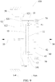
- the first drive shaft 20 can be connected with the planetary carrier 13
- the second drive shaft 30 can be connected with the sun gear 11
- the gear ring 14 is provided with a drive needle axial groove 141
- the drive needle 51 can be slidably arranged in the drive needle axial groove 141.
- the first drive shaft 20 can be connected with the planetary carrier 13
- the second drive shaft 30 can be connected with the gear ring 14
- the drive needle 51 penetrates through the sun gear 11, and the drive needle 51 can rotate along with the sun gear 11 around the central axis of the sun gear 11, i.e., the drive needle 51 can revolve along with the sun gear 11 around the central axis of the sun gear 11.
- Two ends of the drive needle 51 are respectively matched with the drive part 52 and the second joint part 42, and the drive part 52 is configured to be used for driving the drive needle 51 to drive the second joint part 42 to move towards the direction (from left to right as shown in FIG. 1 ) close to the first joint part 41 along the axial direction, so that the second joint part 42 is jointed with the first joint part 41.
- the remaining one (the planetary carrier 13 as shown in FIG. 1 ) of the sun gear 11, the planetary carrier 13 and the gear ring 14 can drive the drive needle 51 to synchronously rotate, and the drive part 52 can drive the drive needle 51 to move from left to right. Because one end of the drive needle 51 is matched with the second joint part 42, the drive needle 51 can synchronously drive the second joint part 42 to move from left to right, and the second joint part 42 continuously approaches the first joint part 41 until the second joint part 42 is jointed with the first joint part 41.
- the first joint part 41 When the first joint part 41 is jointed with the second joint part 42, the first drive shaft 20 and the second drive shaft 30 are mutually locked, and the first drive shaft 20 and the second drive shaft 30 can synchronously rotate, thus the power at the sliding side can be output by means of the other side so as to be favorable for the vehicle to get rid of the trouble.
- a traditional electric locking differential mechanism is formed by additionally arranging an electric actuation locking mechanism on a common open differential mechanism, so that the differential mechanism has a locking function, and the locking of the differential mechanism is realized by means of electrical control.
- the electric locking differential mechanism is usually applied to a centralized drive type fuel vehicle, wherein the power passes through a main reducing gear and the differential mechanism and is then distributed to the left half shaft and the right half shaft respectively, and the speed difference between the left wheel and the right wheel is adjusted by means of the differential mechanism.
- the electric locking differential mechanism cannot be directly applied to an electric vehicle.
- the electric locking differential mechanism has a large volume, and the electric vehicle does not have an engine.
- the drive shaft locking device 100 provided by the present invention is significantly different from the traditional electric locking differential mechanism in structure and implementation mode. Furthermore, by means of arrangement of the joint part drive device 50 and the power joint device 40, the locking of the first drive shaft 20 and the second drive shaft 30 can be realized, thus, the drive shaft locking device 100 has the advantages of simple structure, reliable function implementation, few parts, small volume and low cost.
- the drive shaft locking device 100 can have a small radial size, a small volume and a small occupied space.
- the drive part 52 can comprise: a following part 521, wherein the following part 521 can rotate along with the drive needle 51, and the following part 521 can be braked; the following part 521 is provided with a drive surface 523; and when the following part 521 is braked, the contact matching position of the drive needle 51 and the drive surface 523 is changed by means of the slide of the drive needle 51 on the drive surface 523, so that the drive surface 523 drives the drive needle 51 to move along the axial direction so as to enable the second joint part 42 to be jointed with the first joint part 41.
- the following part 521 and the drive needle 51 can synchronously rotate; after the following part 521 is braked, the rotation speed of the following part 521 is reduced, and the following part 521 and the drive needle 51 have a rotation speed difference, so that the drive needle 51 can slide on the drive surface 523 of the following part 521; and the drive needle 51 after sliding can move along the axial direction relative to the planetary carrier 13, so that the drive needle 51 can drive the second joint part 42 to gradually approach the first joint part 41 until the second joint part 42 is jointed with the first joint part 41.
- the drive part 52 can further comprise: a braking part 522, wherein the braking part 522 is configured to be used for braking the following part 521.
- the braking part 522 can achieve the effect of braking the following part 521.
- the braking part 522 can brake the following part 521.
- the braking part 522 can be configured to brake the following part 521 by means of an electromagnetic force.
- the electromagnetic force is precise and reliable in control, so that the working reliability of the drive shaft locking device 100 can be improved, and the service life of the drive shaft locking device 100 can be prolonged.
- the drive part 52 can be an electromagnetic brake
- the following part 521 constitutes a braking component of the electromagnetic brake
- the braking part 522 constitutes a braking frame of the electromagnetic brake.
- the drive shaft locking device 100 when the drive shaft locking device 100 has the structure that the first drive shaft 20 is connected with the planetary carrier 13, the second drive shaft 30 is connected with the gear ring 14 and the drive needle 51 penetrates through the sun gear 11 and can rotate along with the sun gear 11 around the central axis of the sun gear 11, the planetary carrier 13 can encircle the electromagnetic brake.
- the planetary carrier 13 and the electromagnetic brake are reasonable in arrangement, so that the structure of the drive shaft locking device 100 can be more reliable.
- the power supply mode of the electromagnetic brake is different from a conventional power supply mode.
- a rotational power supply structure or an electric brush ring structure in a motor field can be adopted.
- the following part 521 can hollowly sleeve the first drive shaft 20. Therefore, the matching between the following part 521 and the drive needle 51 can be further facilitated, the axial length of the drive shaft locking device 100 can also be reduced at least to a certain extent, and the volume of the drive shaft locking device 100 can be reduced.
- the drive surface 523 can be an inclined surface or a curved surface.
- the drive surface 523 is configured as an inclined surface or a curved surface to facilitate the slide of the drive needle 51 on the drive surface 523, and the drive needle 51 can be promoted to move along the axial direction.
- the drive surface 523 can comprise: a first section 523a and a second section 523b, wherein the first section 523a is connected with the second section 523b, the connection part of the first section 523a and the second section 523b is the lowest point, and the other ends of the first section 523a and the second section 523b away from the connection part are the highest points. Therefore, when one end of the drive needle 51 is positioned at the lowest point, the first joint part 41 and the second joint part 42 are in a separated state; and when one end of the drive needle 51 is positioned at the highest point or is adjacent to the highest point, the first joint part 41 and the second joint part 42 are in a jointed state.
- the slide of the drive needle 51 between the lowest point and the highest point can be facilitated, the jointing between the first joint part 41 and the second joint part 42 can be facilitated, and the working reliability of the drive shaft locking device 100 can be improved.
- each of the first section 523a and the second section 523b can be of a circular arc.
- the first section 523a and the second section 523b in the arc shape can facilitate the slide of one end of the drive needle 51 on the drive surface 523, and can reduce the moving resistance of the drive needle 51.
- each of the first section 523a and the second section 523b has the same central angle.
- the first section 523a and the second section 523b are basically identical, thereby further facilitating the slide of the drive needle 51 on the drive surface 523.
- multiple sections of drive surfaces 523 can be provided, and the multiple sections of drive surfaces 523 are distributed at intervals along the circumferential direction. Therefore, the number of the drive needles 51 can be corresponding to the number of the drive surfaces 523, so that the number of the drive needles 51 can be increased, a plurality of drive needles 51 can be reliably matched with the second joint part 42, the second joint part 42 can reliably move along the axial direction, and the work of the drive shaft locking device 100 is more reliable.
- connection plane is flush with the highest point.
- the following part 521 can comprise: a following part body 521a and an annular following part flange 521b arranged on the following part body 521a, wherein the end surface of the following part flange 521b facing the drive needle 51 is provided with the drive surface 523.
- the following part body 521a can effectively enhance the structural reliability of the following part 521, and the drive surface 523 can be arranged on the end surface of the following part flange 521b, so that the design difficulty of the drive surface 523 can be lowered, and the structural reliability of the drive surface 523 can be improved.
- the drive surface 523 can be provided with a drive surface limiting groove 523c, and one end of the drive needle 51 is positioned in the drive surface limiting groove 523c.
- the drive surface limiting groove 523c By forming the drive surface limiting groove 523c, one end of the drive needle 51 can be matched in the drive surface limiting groove 523c, so that one end of the drive needle 51 can be prevented from being separated from the drive surface 523 at least to a certain extent, and the reliability and stability of the drive needle 51 moving on the drive surface 523 can be improved.
- the first drive shaft 20 is connected with the sun gear 11
- the second drive shaft 30 is connected with the gear ring 14, and the drive needle 51 penetrates through the planetary carrier 13.
- the planetary gear 12 is mounted on the planetary carrier 13 by means of the planetary gear shaft, and the drive needle 51 and the planetary gear shaft can be the same component. Therefore, by means of reasonable arrangement of the length of the planetary gear shaft, the drive needle 51 can be omitted.
- the planetary gear shaft is reliably arranged on the planetary carrier 13, so that the cost of the drive shaft locking device 100 can be lowered, and the number of the parts of the drive shaft locking device 100 can be reduced.
- the present invention is not limited thereto.
- the first drive shaft 20 is connected with the sun gear 11
- the second drive shaft 30 is connected with the gear ring 14, and the drive needle 51 penetrates through the planetary carrier 13.
- the planetary gear 12 is mounted on the planetary carrier 13 by means of the planetary gear shaft, and the drive needle 51 and the planetary gear shaft are separated.
- the drive needle 51 and the planetary gear shaft are two independent components, so that the change of the planetary carrier 13 can be reduced.
- the drive needle 51 is parallel to the planetary gear shaft 13.
- two planetary carriers 13 can be provided, the two planetary carriers 13 are respectively arranged at two sides of the sun gear 11, and the drive needle 51 penetrates through the two planetary carriers 13. Therefore, the drive needle 51 needs to be matched with the second joint part 42, and the axial length of the drive needle 51 is larger.
- the arrangement stability of the drive needle 51 can be ensured, the structural reliability of the drive shaft locking device 100 can be improved, and the mounting coaxiality of the drive needle 51 can be increased so as to ensure that the drive needle 51 is not easy to deviate when moving along the axial direction.
- the drive shaft locking device 100 can further comprise: a sleeve 60, wherein the sleeve 60 is connected between the gear ring 14 and the second drive shaft 30, the second joint part 42 rotates along with the sleeve 60, and the second joint part 42 can move along the axial direction relative to the sleeve 60.
- the sleeve 60 and the second drive shaft 30 can be integrally formed, and then, the sleeve 60 can be connected with the gear ring 14.
- the second joint part 42 rotates along with the sleeve 60, so that the second joint part 42 can synchronously rotate with the second drive shaft 30 by means of the sleeve 60.
- the second joint part 42 is configured to be capable of moving along the axial direction relative to the sleeve 60 so as to promote the second joint part 42 to move along the axial direction relative to the first joint part 41, and the sleeve 60 and the second drive shaft 30 are not affected, thereby improving the structural reliability and working reliability of the drive shaft locking device 100.
- the sleeve 60 is provided with a sleeve axial groove 61
- the second joint part 42 is provided with a second joint part bulge 421
- the second joint part bulge 421 is arranged in the sleeve axial groove 61 so as to enable the second joint part 42 to rotate along with the sleeve 60, and the second joint part 42 can move along the axial direction relative to the sleeve 60.
- the sleeve axial groove 61 extends along the axial direction, so that the axial movement of the second joint part bulge 421 in the sleeve axial groove 61 can be facilitated, the circumferential position of the second joint part bulge 421 can be limited, and the sleeve 60 can drive the second joint part 42 to synchronously rotate.
- a plurality of sleeve axial grooves 61 can be formed and can be uniformly distributed at intervals in the inner surface of the sleeve 60, and a plurality of second joint part bulges 421 can be provided and is in one-to-one correspondence to the plurality of sleeve axial grooves 61.
- the second joint part 42 can hollowly sleeve the first drive shaft 20.
- the axial size of the drive shaft locking device 100 can be reduced, and the volume of the drive shaft locking device 100 can be reduced.
- the arrangement reliability of the second joint part 42 can also be improved.
- the first joint part 41 and the second joint part 42 can be both contained in the sleeve 60. Therefore, the sleeve 60 can achieve the effect of protecting the first joint part 41 and the second joint part 42, the leakage of lubricating oil of the first joint part 41 and the second joint part 42 can be avoided, and the structural reliability of the drive shaft locking device 100 can be improved.
- the drive shaft locking device 100 can further comprise: elastic devices 70, wherein the elastic devices 70 elastically press against the second joint part 42 so as to enable the second joint part 42 to have the trend of moving towards the direction away from the first joint part 41.
- the elastic devices 70 can drive the second joint part 42 to move towards the direction away from the first joint part 41, and then, the second joint part 42 and the first joint part 41 are separated, so that the first drive shaft 20 and the second drive shaft 30 return to a normal working state.
- the end surface of the first drive shaft 20 close to the second drive shaft 30 is provided with a first drive shaft flange 21, the first drive shaft flange 21 is opposite to the second joint part 42, and the elastic devices 70 elastically press between the first drive shaft flange 21 and the second joint part 42.
- the elastic devices 70 can be spiral springs, and the spiral springs sleeve the first drive shaft 20.
- the spiral springs are reliable in arrangement, and the overall reliability of the drive shaft locking device 100 is better.
- the first joint part 41 sleeves and is fixed on the first drive shaft 20, and the spiral springs are positioned at the outer side of the first joint part 41.
- the structural reliability of the first joint part 41 and the first drive shaft 20 can be improved; and on the other hand, the radial space of the first drive shaft 20 can be reasonably utilized, and the arrangement reliability of the spiral springs and the first joint part 41 can be improved.
- the elastic devices 70 can be contained in the sleeve 60.
- the sleeve 60 can achieve the effect of containing the elastic devices 70, so that the arrangement reliability of the elastic devices 70 can be improved.
- the first joint part 41 is provided with a plurality of first joint teeth 411 distributed along the circumferential direction
- the second joint part 42 is provided with a plurality of second joint teeth 422 distributed along the circumferential direction. It can be understood that when the first joint teeth 411 are matched with the second joint teeth 422, the first joint part 41 is jointed with the second joint part 42. By means of arrangement of the plurality of first joint teeth 411 and the plurality of second joint teeth 422, the matching reliability of the first joint part 41 and the second joint part 42 can be improved.
- the second joint part 42 can be provided with a second joint part limiting groove, and one end of the drive needle 51 is positioned in the second joint part limiting groove.
- the matching reliability between the second joint part 42 and one end of the drive needle 51 can be improved, and the overall working reliability of the drive shaft locking device 100 can be improved.
- the gear ring 14 can be arranged in multiple modes.
- the gear ring 14 has an integrally-formed annular extension part, and the annular extension part constitutes the sleeve 60.
- the gear ring 14 and the sleeve 60 are reliably connected; and on the other hand, the manufacturing difficulty of the drive shaft locking device 100 can be lowered, and the cost of the drive shaft locking device 100 can be lowered.
- a plurality of arc-shaped connecting strips 62 are arranged between the gear ring 14 and the sleeve 60, the plurality of arc-shaped connecting strips 62 are distributed at intervals along the circumferential direction, and the plurality of arc-shaped connecting strips 62 are respectively welded and fixed with the gear ring 14 and the sleeve 60.
- each arc-shaped connecting strip 62 can achieve the effect of fixedly connecting the gear ring 14 with the sleeve 60, and the connecting strips are configured to be arc-shaped, so that the connecting strips can be matched with the gear ring 14 and the edge of the sleeve 60 so as to improve the overall structure reliability of the drive shaft locking device 100.
- the first drive shaft 20 is connected with the sun gear 11
- the second drive shaft 30 is connected with the gear ring 14, and the drive needle 51 penetrates through the planetary carrier 13.
- the planetary carrier 13 is provided with a plurality of convex plates which is distributed at intervals along the circumferential direction, the plurality of convex plates is divided into first convex plates 131 and second convex plates 132, the plurality of first convex plates 131 and the plurality of second convex plates 132 are staggered in the circumferential direction, the first convex plates 131 are used for mounting the planetary gear shaft, and the second convex plates 132 are provided with drive needle support holes for supporting the drive needle 51.
- the planetary gear shaft and the drive needle 51 do not interfere with each other, so that the arrangement reliability of the drive needle 51 on the planetary carrier 13 can be ensured.
- a power-driven system 1000 according to the embodiments of the present invention is described in detail below.
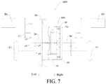
- the power-driven system 1000 can comprise the drive shaft locking device 100 for the vehicle according to the above embodiment, a first motor generator D1, and a second motor generator D2, wherein the first motor generator D1 is in transmission with the first drive shaft 20, and the first motor generator D1 outputs power to one of a pair of wheels; and the second motor generator D2 is in transmission with the second drive shaft 30, and the second motor generator D2 outputs power to the other one of the pair of wheels.
- the drive shaft locking device 100 locks the first drive shaft 20 and the second drive shaft 30, the two wheels synchronously rotate; and when the drive shaft locking device 100 does not lock the first drive shaft 20 and the second drive shaft 30, the first motor generator D1 and the second motor generator D2 work separately so as to drive the corresponding wheels to rotate at a suitable rotation speed.
- the drive shaft locking device 100 can be only applied to a group of wheels.
- a first gear c1, a second gear c2, a third gear c3, a fourth gear c4, a fifth gear c5, and a sixth gear c6 are arranged between the first motor generator D1 and a left front wheel Z1, wherein the first gear c1 is fixed on the motor shaft of the first motor generator D1, the second gear c2 is meshed with the first gear c1, the second gear c2 and the third gear c3 are coaxially fixed, the third gear c3 is meshed with the fourth gear c4, the fourth gear c4 is fixed on the first drive shaft 20, the fifth gear c5 is fixed on the first drive shaft 20, the half shaft of the left front wheel Z1 is connected with the sixth gear c6, and the fifth gear c5 is meshed with the sixth gear c6.
- the power of the first motor generator D1 can be transmitted to the left front wheel Z1 by means of the three groups of meshed gears.
- the first drive shaft 20 can also achieve corresponding effects in transmission processes and can achieve the effects of speed reduction and torque increase between the first gear c1 and the second gear c2 as well as between the third gear c3 and the fourth gear c4.
- the drive shaft locking device 100 in the power-driven system 1000, can be applied to two groups of wheels.
- two drive shaft locking devices 100 can be provided, wherein one drive shaft locking device 100 is matched in the left front wheel Z1 and a right front wheel Y1, the first motor generator D1 is in transmission with the first drive shaft 20 of the drive shaft locking device 100, and the second motor generator D2 is in transmission with the second drive shaft 30 of the drive shaft locking device 100.
- the other drive shaft locking device 100 is matched in a left rear wheel Z2 and a right rear wheel Y2, a third motor generator D3 is in transmission with the first drive shaft 20 of the drive shaft locking device 100, and a fourth motor generator D4 is in transmission with the second drive shaft 30 of the drive shaft locking device 100.
- the first motor generator D1 and the second motor generator D2 work separately, and a controller of the vehicle can control the first motor generator D1 and the second motor generator D2 to work in the same direction and at the same speed, so that the left front wheel Z1 and the right front wheel Y1 can rotate at the same speed and in the same direction.
- the controller can control the first motor generator D1 and the second motor generator D2 to work in the same direction and at different rotation speeds. For example, when the vehicle needs to turn left, the rotation speed of the first motor generator D1 can be less than the rotation speed of the second motor generator D2, and then, the rotation speed of the right front wheel Y1 is greater than the rotation speed of the left front wheel Z1, so that the vehicle turns left.
- one end of the drive needle 51 in the drive shaft locking device 100 is positioned at the lowest point of the drive surface 523 of the following part 521, and at this time, the drive needle 51 and the following part 521 synchronously rotate.
- the braking frame brakes the braking component to enable the rotation speed of the braking component to be inhibited
- a rotation speed difference is generated between the drive needle 51 and the braking component
- the drive needle 51 slides on the drive surface 523 of the braking component
- the drive needle 51 can slide from the lowest point of the drive surface 523 to the highest point or the position adjacent to the highest point
- the drive needle 51 moves towards one side of the second joint part 42 along the axial direction
- the drive needle 51 can also drive the second joint part 42 to gradually approach the first joint part 41 until the first joint part 41 is jointed with the second joint part 42, and at this time, the first drive shaft 20 and the second drive shaft 30 synchronously rotate, thereby improving the capability of the vehicle to get rid of the trouble.
- the driver can press the electromagnetic brake again, the electromagnetic brake is powered off, the elastic devices push the second joint part 42 to move towards the direction away from the first joint part 41 along the axial direction, in this process, the drive needle 51 moves along with the second joint part 42 along the axial direction, one end of the drive needle 51 matched with the drive surface 523 can gradually slide to the lowest point from the highest point or the position adjacent to the highest point, at this time, the second joint part 42 and the first joint part 41 are completely separated, and the vehicle can continue to run normally along a straight line or to turn normally.
- the vehicle according to the embodiments of the present invention comprises the power-driven system 1000 according to the above embodiment.
Landscapes
- Engineering & Computer Science (AREA)
- Mechanical Engineering (AREA)
- Chemical & Material Sciences (AREA)
- Combustion & Propulsion (AREA)
- Transportation (AREA)
- General Engineering & Computer Science (AREA)
- Physics & Mathematics (AREA)
- Electromagnetism (AREA)
- Retarders (AREA)
Abstract
The present invention discloses a drive shaft locking device, a power-driven system, and a vehicle. The drive shaft locking device comprises a planetary gear mechanism, wherein the planetary gear mechanism comprises a sun gear, a planetary gear, a planetary carrier, and a gear ring; a first drive shaft, a second drive shaft, and a power joint device, wherein the power joint device comprises a first joint part and a second joint part, the first drive shaft is connected with one of the sun gear, the planetary carrier and the gear ring, the second drive shaft is connected with another one of the sun gear, the planetary carrier and the gear ring, the first drive shaft and the first joint part synchronously rotate, and the second drive shaft and the second joint part synchronously rotate; and a joint part drive device which comprises a drive needle and a drive part, wherein the drive part is used for driving the drive needle to drive the second joint part to move towards the direction close to the first joint part along the axial direction, so that the second joint part is jointed with the first joint part. Therefore, the drive shaft locking device can lock two drive shafts and improve the capability of the vehicle to get rid of the trouble.
Description
- This application claims the priority of Chinese Patent Application Serial No.
201611226794.9 - The present invention relates to the technical field of vehicles, and particularly relates to a drive shaft locking device for a vehicle, a power-driven system with the drive shaft locking device, and a vehicle with the power-driven system.
- In related technologies, a new energy vehicle adopts a distributed drive mode. Wheels at two sides are respectively driven by two motors, and the rotation speeds and torques of the left and right wheels can be independently adjusted by a controller respectively, thus canceling a differential mechanism. However, under some road conditions where the vehicle is easy to slide, a left half shaft and a right half shaft still need to be locked so as to improve the trafficability. If a traditional electric locking differential mechanism is applied to a distributed-drive new energy vehicle, the differential function of the differential mechanism is wasted. Furthermore, the traditional electric locking differential mechanism has a complicated structure, has more parts and occupies a larger space.
- An objective of the present invention is to at least resolve one of the technical problems in the related art to some extent. Therefore, the present invention provides a drive shaft locking device which is especially suitable for an electric vehicle. The drive shaft locking device can lock two drive shafts and is favorable for the vehicle to get rid of the trouble.
- The present invention further provides a power-driven system.
- The present invention further provides a vehicle.
- The drive shaft locking device for the vehicle, provided by the present invention, comprises a planetary gear mechanism, wherein the planetary gear mechanism comprises a sun gear, a planetary gear, a planetary carrier, and a gear ring; a first drive shaft, a second drive shaft, and a power joint device, wherein the power joint device comprises a first joint part and a second joint part, the first drive shaft is connected with one of the sun gear, the planetary carrier and the gear ring, the first drive shaft is further configured to synchronously rotate with the first joint part, the second drive shaft is connected with another one of the sun gear, the planetary carrier and the gear ring, and the second drive shaft is further configured to synchronously rotate with the second joint part; and a joint part drive device, wherein the joint part drive device comprises a drive needle and a drive part, wherein the drive needle is configured to be capable of rotating around the central axis of the sun gear along with the remaining one of the sun gear, the planetary carrier and the gear ring, and be capable of moving along the axial direction relative to the remaining one of the sun gear, the planetary carrier and the gear ring, two ends of the drive needle are respectively matched with the drive part and the second joint part, and the drive part is configured to be used for driving the drive needle to drive the second joint part to move towards the direction close to the first joint part along the axial direction, so that the second joint part is jointed with the first joint part.
- According to the drive shaft locking device provided by the present invention, when the first joint part is jointed with the second joint part, the first drive shaft and the second drive shaft are mutually locked, and the first drive shaft and the second drive shaft can synchronously rotate, thereby being favorable for the vehicle to get rid of the trouble. Furthermore, by means of arrangement of the joint part drive device and the power joint device, the locking of the first drive shaft and the second drive shaft can be realized. Thus, the drive shaft locking device has the advantages of simple structure, reliable function implementation, few parts, small volume and low cost.
- In addition, the drive shaft locking device provided by the present invention can also have the following distinguishing technical features:
- In some examples of the present invention, the drive part comprises: a following part, wherein the following part can rotate along with the drive needle, and the following part can be braked; the following part is provided with a drive surface; and when the following part is braked, the drive surface drives the drive needle to move along the axial direction by means of the slide of the drive needle on the drive surface, so that the second joint part is jointed with the first joint part.
- In some examples of the present invention, the drive part further comprises: a braking part, wherein the braking part is configured to be used for braking the following part.
- In some examples of the present invention, the braking part is configured to brake the following part by means of an electromagnetic force.
- In some examples of the present invention, the drive part is an electromagnetic brake, the following part constitutes a braking component of the electromagnetic brake, and the braking part constitutes a braking frame of the electromagnetic brake.
- In some examples of the present invention, the following part hollowly sleeves the first drive shaft.
- In some examples of the present invention, the drive surface is an inclined surface or a curved surface.
- In some examples of the present invention, the drive surface comprises a first section and a second section, wherein the first section is connected with the second section, the connection part of the first section and the second section is the lowest point, and the other ends of the first section and the second section away from the connection part are the highest points.
- In some examples of the present invention, the following part comprises: a following part body and an annular following part flange arranged on the following part body, wherein the end surface of the following part flange facing the drive needle is provided with the drive surface.
- In some examples of the present invention, the drive surface is provided with a drive surface limiting groove, and one end of the drive needle is positioned in the drive surface limiting groove.
- In some examples of the present invention, the first drive shaft is connected with the sun gear, the second drive shaft is connected with the gear ring, and the drive needle penetrates through the planetary carrier; and the planetary gear is mounted on the planetary carrier by means of a planetary gear shaft, and the drive needle and the planetary gear shaft are the same component.
- In some examples of the present invention, the first drive shaft is connected with the sun gear, and the second drive shaft is connected with the gear ring; and two planetary carriers are provided and are respectively arranged at two sides of the sun gear, and the drive needle penetrates through the two planetary carriers.
- In some examples of the present invention, the first drive shaft is connected with the sun gear, the second drive shaft is connected with the gear ring, and the drive needle penetrates through the planetary carrier; and the drive shaft locking device further comprises: a sleeve, wherein the sleeve is connected between the gear ring and the second drive shaft, and the second joint part rotates along with the sleeve and can move along the axial direction relative to the sleeve.
- In some examples of the present invention, the sleeve is provided with a sleeve axial groove, the second joint part is provided with a second joint part bulge, and the second joint part bulge is arranged in the sleeve axial groove, so that the second joint part can rotate along with the sleeve and can move along the axial direction relative to the sleeve.
- In some examples of the present invention, the second joint part hollowly sleeves the first drive shaft.
- In some examples of the present invention, the first joint part and the second joint part are both contained in the sleeve.
- In some examples of the present invention, the drive shaft locking device further comprises: elastic devices, wherein the elastic devices elastically press against the second joint part so as to enable the second joint part to have the trend of moving towards the direction away from the first joint part.
- In some examples of the present invention, the end surface of the first drive shaft close to the second drive shaft is provided with a first drive shaft flange, the first drive shaft flange is opposite to the second joint part, and the elastic devices elastically press between the first drive shaft flange and the second joint part.
- In some examples of the present invention, the elastic devices are spiral springs and sleeve the first drive shaft.
- In some examples of the present invention, the first joint part sleeves and is fixed on the first drive shaft, and the spiral springs are positioned at the outer side of the first joint part.
- In some examples of the present invention, the elastic devices are contained in the sleeve.
- In some examples of the present invention, the first joint part is provided with a plurality of first joint teeth distributed along the circumferential direction, and the second joint part is provided with a plurality of second joint teeth distributed along the circumferential direction.
- In some examples of the present invention, the second joint part is provided with a second joint part limiting groove, and one end of the drive needle is positioned in the second joint part limiting groove.
- In some examples of the present invention, the gear ring has an integrally-formed annular extension part, and the annular extension part constitutes the sleeve.
- In some examples of the present invention, a plurality of arc-shaped connecting strips is arranged between the gear ring and the sleeve, and the plurality of arc-shaped connecting strips is distributed at intervals along the circumferential direction and is respectively welded and fixed with the gear ring and the sleeve.
- In some examples of the present invention, the first drive shaft is connected with the sun gear, the second drive shaft is connected with the gear ring, and the drive needle penetrates through the planetary carrier; and the planetary carrier is provided with a plurality of convex plates which is distributed at intervals along the circumferential direction, the plurality of convex plates is divided into first convex plates and second convex plates, the plurality of first convex plates and the plurality of second convex plates are staggered in the circumferential direction, the first convex plates are used for mounting the planetary gear shaft, and the second convex plates are provided with drive needle support holes for supporting the drive needle.
- In some examples of the present invention, the first drive shaft is connected with the planetary carrier, the second drive shaft is connected with the sun gear, the gear ring is provided with a drive needle axial groove, and the drive needle is slidably arranged in the drive needle axial groove.
- In some examples of the present invention, the first drive shaft is connected with the planetary carrier, the second drive shaft is connected with the gear ring, and the drive needle penetrates through the sun gear and can rotate along with the sun gear around the central axis of the sun gear; and the planetary carrier encircles the electromagnetic brake.
- The power-driven system provided by the present invention comprises: the drive shaft locking device for the vehicle; a first motor generator, wherein the first motor generator is in transmission with the first drive shaft and outputs power to one of a pair of wheels; and a second motor generator, wherein the second motor generator is in transmission with the second drive shaft and outputs power to the other one of the pair of wheels.
- The power-driven system provided by the present invention comprises: two drive shaft locking devices for the vehicle; a first motor generator, wherein the first motor generator is in transmission with the first drive shaft of one drive shaft locking device and outputs power to the left front wheel; a second motor generator, wherein the second motor generator is in transmission with the second drive shaft of one drive shaft locking device and outputs power to the right front wheel; a third motor generator, wherein the third motor generator is in transmission with the first drive shaft of the other one drive shaft locking device and outputs power to the left rear wheel; and a fourth motor generator, wherein the fourth motor generator is in transmission with the second drive shaft of the other one drive shaft locking device and outputs power to the right rear wheel.
- The beneficial effects of the power-driven system are the same as the beneficial effects of the drive shaft locking device, so that the descriptions are omitted herein.
- The vehicle provided by the present invention comprises the power-driven system.
- The beneficial effects of the vehicle are the same as the beneficial effects of the power-driven system, so that the descriptions are omitted herein.
-
-
FIG. 1 is a schematic diagram of a drive shaft locking device according to an embodiment of the present invention; -
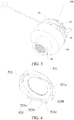
FIG. 2 is an exploded diagram of a drive shaft locking device according to an embodiment of the present invention; -
FIG. 3 is a structural diagram of a drive shaft locking device according to an embodiment of the present invention; -
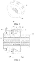
FIG. 4 is a structural diagram of a following part; -
FIG. 5 is a structural diagram of a sleeve and a second drive shaft; -
FIG. 6 is a sectional view of a drive shaft locking device according to an embodiment of the present invention; -
FIG. 7 is a schematic diagram of a power-driven system according to an embodiment of the present invention; -
FIG. 8 is a schematic diagram of a power-driven system according to an embodiment of the present invention; -
FIG. 9 is a schematic diagram of a drive shaft locking device according to another embodiment of the present invention; and -
FIG. 10 is a schematic diagram of a drive shaft locking device according to still another embodiment of the present invention. -
- Power-driven
system 1000; - Drive
shaft locking device 100; -
Planetary gear mechanism 10;Sun gear 11;Planetary gear 12;Planetary carrier 13; Firstconvex plate 131; Secondconvex plate 132; -
Gear ring 14; Drive needleaxial groove 141; - First drive
shaft 20; First driveshaft flange 21; -
Second drive shaft 30; - Power
joint device 40; Firstjoint part 41; Firstjoint tooth 411; Secondjoint part 42; Secondjoint part bulge 421; Secondjoint tooth 422; - Joint
part drive device 50;Drive needle 51; Drivepart 52; Followingpart 521; Followingpart body 521a; Followingpart flange 521b; - Braking
part 522; -
Drive surface 523;First section 523a;Second section 523b; Drivesurface limiting groove 523c; -
Sleeve 60; Sleeveaxial groove 61; Arc-shaped connectingstrip 62; -
Elastic device 70; - First motor generator D1; Second motor generator D2; Third motor generator D3; Fourth motor generator D4;
- Left front wheel Z1; Left rear wheel Z2; Right front wheel Y1; Right rear wheel Y2.
- The embodiments of the present invention are described in detail below, and the examples of the embodiments are as shown in the drawings. The following embodiments described with reference to the accompanying drawings are exemplary, and are intended to describe the present invention and cannot be construed as a limitation to the present invention.
- A drive
shaft locking device 100 according to the embodiments of the present invention is described in detail below with reference to the accompanying drawings. The driveshaft locking device 100 can be applied to a vehicle and is particularly applicable to a new energy vehicle adopting distributed drive. The driveshaft locking device 100 can be used for locking two drive shafts so as to enable left and right wheels to synchronously rotate, thereby greatly improving the capability of the vehicle to get rid of the trouble. The vehicle can be an electric vehicle, but is not limited thereto. - As shown in
FIG. 1 andFIG. 2 , the driveshaft locking device 100 according to the embodiments of the present invention can comprise: aplanetary gear mechanism 10, afirst drive shaft 20, asecond drive shaft 30, a powerjoint device 40, and a jointpart drive device 50. - The
planetary gear mechanism 10 comprises asun gear 11, aplanetary gear 12, aplanetary carrier 13, and agear ring 14, wherein theplanetary gear 12 can be rotationally mounted on theplanetary carrier 13, and theplanetary gear 12 is meshed between thesun gear 11 and thegear ring 14, therefore, theplanetary gear 12 can transmit power between thesun gear 11 and thegear ring 14. A plurality of, for example three,planetary gears 12 can be provided, and the threeplanetary gears 12 can be uniformly distributed with respect to the central axis of thesun gear 11. A planetary gear shaft can be mounted on theplanetary carrier 13, and theplanetary gear 12 is mounted on the planetary gear shaft. - The
first drive shaft 20 and thesecond drive shaft 30 are two independent shafts. For example, thefirst drive shaft 20 can be in transmission with a left wheel, and thesecond drive shaft 30 can be in transmission with a right wheel. The axis of thefirst drive shaft 20 and the axis of thesecond drive shaft 30 can be collinear. But the present invention is not limited thereto. For example, thefirst drive shaft 20 can be a right half shaft, and thesecond drive shaft 30 can be a left half shaft. - The power
joint device 40 comprises a firstjoint part 41 and a secondjoint part 42. Thefirst drive shaft 20 is connected with one of thesun gear 11, theplanetary carrier 13 and thegear ring 14, and thefirst drive shaft 20 is further configured to synchronously rotate (namely rotate at the same speed and in the same direction) with the firstjoint part 41. Thesecond drive shaft 30 is connected with another one of thesun gear 11, theplanetary carrier 13 and thegear ring 14, and thesecond drive shaft 30 is further configured to synchronously rotate (namely rotate at the same speed and in the same direction) with the secondjoint part 42. - The joint
part drive device 50 can comprise: adrive needle 51 and adrive part 52, wherein thedrive needle 51 is configured to be capable of rotating around the central axis of thesun gear 11 along with the remaining one of thesun gear 11, theplanetary carrier 13 and thegear ring 14, and thedrive needle 51 is configured to be capable of moving along the axial direction relative to the remaining one of thesun gear 11, theplanetary carrier 13 and thegear ring 14. - For example, as shown in
FIG. 1 , thefirst drive shaft 20 can be connected with thesun gear 11, so that thefirst drive shaft 20 and thesun gear 11 can synchronously rotate, i.e., thefirst drive shaft 20, thesun gear 11 and the firstjoint part 41 can synchronously rotate; and thesecond drive shaft 30 can be connected with thegear ring 14, so that thesecond drive shaft 30 and thegear ring 14 can synchronously rotate, i.e., thesecond drive shaft 30, thegear ring 14 and the secondjoint part 42 can synchronously rotate. Thedrive needle 51 can revolve around the central axis of thesun gear 11 along with theplanetary carrier 13, and thedrive needle 51 can move along the axial direction relative to theplanetary carrier 13. In other words, thedrive needle 51 and theplanetary carrier 13 can synchronously rotate, but thedrive needle 51 can move along the axial direction relative to theplanetary carrier 13. Therefore, thedrive needle 51 penetrates through theplanetary carrier 13, and then, theplanetary carrier 13 can drive thedrive needle 51 to synchronously rotate without hindering the axial movement of thedrive needle 51. - Furthermore, as shown in
FIG. 9 , thefirst drive shaft 20 can be connected with theplanetary carrier 13, thesecond drive shaft 30 can be connected with thesun gear 11, thegear ring 14 is provided with a drive needleaxial groove 141, and thedrive needle 51 can be slidably arranged in the drive needleaxial groove 141. - Furthermore, as shown in
FIG. 10 , thefirst drive shaft 20 can be connected with theplanetary carrier 13, thesecond drive shaft 30 can be connected with thegear ring 14, thedrive needle 51 penetrates through thesun gear 11, and thedrive needle 51 can rotate along with thesun gear 11 around the central axis of thesun gear 11, i.e., thedrive needle 51 can revolve along with thesun gear 11 around the central axis of thesun gear 11. - Two ends of the
drive needle 51 are respectively matched with thedrive part 52 and the secondjoint part 42, and thedrive part 52 is configured to be used for driving thedrive needle 51 to drive the secondjoint part 42 to move towards the direction (from left to right as shown inFIG. 1 ) close to the firstjoint part 41 along the axial direction, so that the secondjoint part 42 is jointed with the firstjoint part 41. - In other words, the remaining one (the
planetary carrier 13 as shown inFIG. 1 ) of thesun gear 11, theplanetary carrier 13 and thegear ring 14 can drive thedrive needle 51 to synchronously rotate, and thedrive part 52 can drive thedrive needle 51 to move from left to right. Because one end of thedrive needle 51 is matched with the secondjoint part 42, thedrive needle 51 can synchronously drive the secondjoint part 42 to move from left to right, and the secondjoint part 42 continuously approaches the firstjoint part 41 until the secondjoint part 42 is jointed with the firstjoint part 41. When the firstjoint part 41 is jointed with the secondjoint part 42, thefirst drive shaft 20 and thesecond drive shaft 30 are mutually locked, and thefirst drive shaft 20 and thesecond drive shaft 30 can synchronously rotate, thus the power at the sliding side can be output by means of the other side so as to be favorable for the vehicle to get rid of the trouble. - A traditional electric locking differential mechanism is formed by additionally arranging an electric actuation locking mechanism on a common open differential mechanism, so that the differential mechanism has a locking function, and the locking of the differential mechanism is realized by means of electrical control. The electric locking differential mechanism is usually applied to a centralized drive type fuel vehicle, wherein the power passes through a main reducing gear and the differential mechanism and is then distributed to the left half shaft and the right half shaft respectively, and the speed difference between the left wheel and the right wheel is adjusted by means of the differential mechanism. However, the electric locking differential mechanism cannot be directly applied to an electric vehicle. The electric locking differential mechanism has a large volume, and the electric vehicle does not have an engine.
- Therefore, the drive
shaft locking device 100 provided by the present invention is significantly different from the traditional electric locking differential mechanism in structure and implementation mode. Furthermore, by means of arrangement of the jointpart drive device 50 and the powerjoint device 40, the locking of thefirst drive shaft 20 and thesecond drive shaft 30 can be realized, thus, the driveshaft locking device 100 has the advantages of simple structure, reliable function implementation, few parts, small volume and low cost. - As shown in
FIG. 1 , theplanetary gear mechanism 10, the powerjoint device 40, thefirst drive shaft 20 and thesecond drive shaft 30 are coaxially arranged. Therefore, the driveshaft locking device 100 can have a small radial size, a small volume and a small occupied space. - As shown in
FIG. 1 , thedrive part 52 can comprise: a followingpart 521, wherein thefollowing part 521 can rotate along with thedrive needle 51, and thefollowing part 521 can be braked; thefollowing part 521 is provided with adrive surface 523; and when thefollowing part 521 is braked, the contact matching position of thedrive needle 51 and thedrive surface 523 is changed by means of the slide of thedrive needle 51 on thedrive surface 523, so that thedrive surface 523 drives thedrive needle 51 to move along the axial direction so as to enable the secondjoint part 42 to be jointed with the firstjoint part 41. It can be understood that before thefollowing part 521 is braked, the followingpart 521 and thedrive needle 51 can synchronously rotate; after thefollowing part 521 is braked, the rotation speed of thefollowing part 521 is reduced, and thefollowing part 521 and thedrive needle 51 have a rotation speed difference, so that thedrive needle 51 can slide on thedrive surface 523 of thefollowing part 521; and thedrive needle 51 after sliding can move along the axial direction relative to theplanetary carrier 13, so that thedrive needle 51 can drive the secondjoint part 42 to gradually approach the firstjoint part 41 until the secondjoint part 42 is jointed with the firstjoint part 41. - Further, as shown in
FIG. 1 , thedrive part 52 can further comprise: abraking part 522, wherein thebraking part 522 is configured to be used for braking thefollowing part 521. In other words, thebraking part 522 can achieve the effect of braking thefollowing part 521. When the firstjoint part 41 and the secondjoint part 42 need to be jointed, thebraking part 522 can brake thefollowing part 521. - Preferably, the
braking part 522 can be configured to brake thefollowing part 521 by means of an electromagnetic force. The electromagnetic force is precise and reliable in control, so that the working reliability of the driveshaft locking device 100 can be improved, and the service life of the driveshaft locking device 100 can be prolonged. For example, thedrive part 52 can be an electromagnetic brake, the followingpart 521 constitutes a braking component of the electromagnetic brake, and thebraking part 522 constitutes a braking frame of the electromagnetic brake. By adopting the control mode of the electromagnetic brake and the planetary gear mechanism, the control system of the driveshaft locking device 100 can be simplified, and the system reliability can be improved. - Specifically, as shown in
FIG. 10 , when the driveshaft locking device 100 has the structure that thefirst drive shaft 20 is connected with theplanetary carrier 13, thesecond drive shaft 30 is connected with thegear ring 14 and thedrive needle 51 penetrates through thesun gear 11 and can rotate along with thesun gear 11 around the central axis of thesun gear 11, theplanetary carrier 13 can encircle the electromagnetic brake. Theplanetary carrier 13 and the electromagnetic brake are reasonable in arrangement, so that the structure of the driveshaft locking device 100 can be more reliable. - In the present embodiment, because the
planetary carrier 13 encircles the electromagnetic brake, the power supply mode of the electromagnetic brake is different from a conventional power supply mode. For example, a rotational power supply structure or an electric brush ring structure in a motor field can be adopted. - Optionally, as shown in
FIG. 1 , the followingpart 521 can hollowly sleeve thefirst drive shaft 20. Therefore, the matching between thefollowing part 521 and thedrive needle 51 can be further facilitated, the axial length of the driveshaft locking device 100 can also be reduced at least to a certain extent, and the volume of the driveshaft locking device 100 can be reduced. - According to a specific embodiment of the present invention, as shown in
FIG. 4 , thedrive surface 523 can be an inclined surface or a curved surface. Thedrive surface 523 is configured as an inclined surface or a curved surface to facilitate the slide of thedrive needle 51 on thedrive surface 523, and thedrive needle 51 can be promoted to move along the axial direction. - Further, the
drive surface 523 can comprise: afirst section 523a and asecond section 523b, wherein thefirst section 523a is connected with thesecond section 523b, the connection part of thefirst section 523a and thesecond section 523b is the lowest point, and the other ends of thefirst section 523a and thesecond section 523b away from the connection part are the highest points. Therefore, when one end of thedrive needle 51 is positioned at the lowest point, the firstjoint part 41 and the secondjoint part 42 are in a separated state; and when one end of thedrive needle 51 is positioned at the highest point or is adjacent to the highest point, the firstjoint part 41 and the secondjoint part 42 are in a jointed state. By means of reasonable arrangement of thedrive surface 523, the slide of thedrive needle 51 between the lowest point and the highest point can be facilitated, the jointing between the firstjoint part 41 and the secondjoint part 42 can be facilitated, and the working reliability of the driveshaft locking device 100 can be improved. - Preferably, each of the
first section 523a and thesecond section 523b can be of a circular arc. Thefirst section 523a and thesecond section 523b in the arc shape can facilitate the slide of one end of thedrive needle 51 on thedrive surface 523, and can reduce the moving resistance of thedrive needle 51. - Optionally, each of the
first section 523a and thesecond section 523b has the same central angle. Thus, thefirst section 523a and thesecond section 523b are basically identical, thereby further facilitating the slide of thedrive needle 51 on thedrive surface 523. - Optionally, multiple sections of drive surfaces 523 can be provided, and the multiple sections of drive surfaces 523 are distributed at intervals along the circumferential direction. Therefore, the number of the drive needles 51 can be corresponding to the number of the drive surfaces 523, so that the number of the drive needles 51 can be increased, a plurality of drive needles 51 can be reliably matched with the second
joint part 42, the secondjoint part 42 can reliably move along the axial direction, and the work of the driveshaft locking device 100 is more reliable. - Multiple sections of drive surfaces 523 can be connected by means of a connection plane, and the connection plane is flush with the highest point. Thus, the structural reliability of the
drive surface 523 of thefollowing part 521 can be improved at least to a certain extent, and the structural reliability of the driveshaft locking device 100 can be improved. - According to an optional embodiment of the present invention, as shown in
FIG. 4 , the followingpart 521 can comprise: a followingpart body 521a and an annular followingpart flange 521b arranged on thefollowing part body 521a, wherein the end surface of thefollowing part flange 521b facing thedrive needle 51 is provided with thedrive surface 523. Thefollowing part body 521a can effectively enhance the structural reliability of thefollowing part 521, and thedrive surface 523 can be arranged on the end surface of thefollowing part flange 521b, so that the design difficulty of thedrive surface 523 can be lowered, and the structural reliability of thedrive surface 523 can be improved. - Further, as shown in
FIG. 4 , thedrive surface 523 can be provided with a drivesurface limiting groove 523c, and one end of thedrive needle 51 is positioned in the drivesurface limiting groove 523c. By forming the drivesurface limiting groove 523c, one end of thedrive needle 51 can be matched in the drivesurface limiting groove 523c, so that one end of thedrive needle 51 can be prevented from being separated from thedrive surface 523 at least to a certain extent, and the reliability and stability of thedrive needle 51 moving on thedrive surface 523 can be improved. - According to a specific embodiment of the present invention, as shown in
FIG. 1 to FIG. 3 , thefirst drive shaft 20 is connected with thesun gear 11, thesecond drive shaft 30 is connected with thegear ring 14, and thedrive needle 51 penetrates through theplanetary carrier 13. Theplanetary gear 12 is mounted on theplanetary carrier 13 by means of the planetary gear shaft, and thedrive needle 51 and the planetary gear shaft can be the same component. Therefore, by means of reasonable arrangement of the length of the planetary gear shaft, thedrive needle 51 can be omitted. Furthermore, the planetary gear shaft is reliably arranged on theplanetary carrier 13, so that the cost of the driveshaft locking device 100 can be lowered, and the number of the parts of the driveshaft locking device 100 can be reduced. - Of course, the present invention is not limited thereto. According to another specific embodiment of the present invention, the
first drive shaft 20 is connected with thesun gear 11, thesecond drive shaft 30 is connected with thegear ring 14, and thedrive needle 51 penetrates through theplanetary carrier 13. Theplanetary gear 12 is mounted on theplanetary carrier 13 by means of the planetary gear shaft, and thedrive needle 51 and the planetary gear shaft are separated. Thedrive needle 51 and the planetary gear shaft are two independent components, so that the change of theplanetary carrier 13 can be reduced. By means of reasonable arrangement of thedrive needle 51, the driveshaft locking device 100 can realize the corresponding locking function. Optionally, in the present embodiment, thedrive needle 51 is parallel to theplanetary gear shaft 13. - As shown in
FIG. 1 , twoplanetary carriers 13 can be provided, the twoplanetary carriers 13 are respectively arranged at two sides of thesun gear 11, and thedrive needle 51 penetrates through the twoplanetary carriers 13. Therefore, thedrive needle 51 needs to be matched with the secondjoint part 42, and the axial length of thedrive needle 51 is larger. By means of arrangement of the two separatedplanetary carriers 13, the arrangement stability of thedrive needle 51 can be ensured, the structural reliability of the driveshaft locking device 100 can be improved, and the mounting coaxiality of thedrive needle 51 can be increased so as to ensure that thedrive needle 51 is not easy to deviate when moving along the axial direction. - Optionally, as shown in
FIG. 1 ,FIG. 3 ,FIG. 5 and FIG. 6 , the driveshaft locking device 100 can further comprise: asleeve 60, wherein thesleeve 60 is connected between thegear ring 14 and thesecond drive shaft 30, the secondjoint part 42 rotates along with thesleeve 60, and the secondjoint part 42 can move along the axial direction relative to thesleeve 60. Thesleeve 60 and thesecond drive shaft 30 can be integrally formed, and then, thesleeve 60 can be connected with thegear ring 14. The secondjoint part 42 rotates along with thesleeve 60, so that the secondjoint part 42 can synchronously rotate with thesecond drive shaft 30 by means of thesleeve 60. The secondjoint part 42 is configured to be capable of moving along the axial direction relative to thesleeve 60 so as to promote the secondjoint part 42 to move along the axial direction relative to the firstjoint part 41, and thesleeve 60 and thesecond drive shaft 30 are not affected, thereby improving the structural reliability and working reliability of the driveshaft locking device 100. - Further, as shown in
FIG. 2 andFIG. 5 , thesleeve 60 is provided with a sleeveaxial groove 61, the secondjoint part 42 is provided with a secondjoint part bulge 421, the secondjoint part bulge 421 is arranged in the sleeveaxial groove 61 so as to enable the secondjoint part 42 to rotate along with thesleeve 60, and the secondjoint part 42 can move along the axial direction relative to thesleeve 60. The sleeveaxial groove 61 extends along the axial direction, so that the axial movement of the secondjoint part bulge 421 in the sleeveaxial groove 61 can be facilitated, the circumferential position of the secondjoint part bulge 421 can be limited, and thesleeve 60 can drive the secondjoint part 42 to synchronously rotate. A plurality of sleeveaxial grooves 61 can be formed and can be uniformly distributed at intervals in the inner surface of thesleeve 60, and a plurality of second joint part bulges 421 can be provided and is in one-to-one correspondence to the plurality of sleeveaxial grooves 61. - As shown in
FIG. 1 , the secondjoint part 42 can hollowly sleeve thefirst drive shaft 20. By means of arrangement of the secondjoint part 42, the axial size of the driveshaft locking device 100 can be reduced, and the volume of the driveshaft locking device 100 can be reduced. In addition, the arrangement reliability of the secondjoint part 42 can also be improved. - Optionally, as shown in
FIG. 1 andFIG. 6 , the firstjoint part 41 and the secondjoint part 42 can be both contained in thesleeve 60. Therefore, thesleeve 60 can achieve the effect of protecting the firstjoint part 41 and the secondjoint part 42, the leakage of lubricating oil of the firstjoint part 41 and the secondjoint part 42 can be avoided, and the structural reliability of the driveshaft locking device 100 can be improved. - As shown in
FIG. 1 , the driveshaft locking device 100 can further comprise:elastic devices 70, wherein theelastic devices 70 elastically press against the secondjoint part 42 so as to enable the secondjoint part 42 to have the trend of moving towards the direction away from the firstjoint part 41. It can be understood that when the locking state between thefirst drive shaft 20 and thesecond drive shaft 30 needs to be released, the secondjoint part 42 needs to be away from the firstjoint part 41, at this time, thebraking part 522 stops braking thefollowing part 521, theelastic devices 70 can drive the secondjoint part 42 to move towards the direction away from the firstjoint part 41, and then, the secondjoint part 42 and the firstjoint part 41 are separated, so that thefirst drive shaft 20 and thesecond drive shaft 30 return to a normal working state. - Optionally, as shown in
FIG. 2 andFIG. 6 , the end surface of thefirst drive shaft 20 close to thesecond drive shaft 30 is provided with a firstdrive shaft flange 21, the firstdrive shaft flange 21 is opposite to the secondjoint part 42, and theelastic devices 70 elastically press between the firstdrive shaft flange 21 and the secondjoint part 42. By pressing theelastic devices 70 against one end of the firstdrive shaft flange 21, the arrangement reliability of theelastic devices 70 can be ensured, and the axial movement of the secondjoint part 42 can be facilitated. Preferably, theelastic devices 70 can be spiral springs, and the spiral springs sleeve thefirst drive shaft 20. Thus, the spiral springs are reliable in arrangement, and the overall reliability of the driveshaft locking device 100 is better. - As shown in
FIG. 2 , the firstjoint part 41 sleeves and is fixed on thefirst drive shaft 20, and the spiral springs are positioned at the outer side of the firstjoint part 41. Thus, on the one hand, the structural reliability of the firstjoint part 41 and thefirst drive shaft 20 can be improved; and on the other hand, the radial space of thefirst drive shaft 20 can be reasonably utilized, and the arrangement reliability of the spiral springs and the firstjoint part 41 can be improved. - Optionally, as shown in
FIG. 1 andFIG. 6 , theelastic devices 70 can be contained in thesleeve 60. Thesleeve 60 can achieve the effect of containing theelastic devices 70, so that the arrangement reliability of theelastic devices 70 can be improved. - According to a specific embodiment of the present invention, as shown in
FIG. 2 , the firstjoint part 41 is provided with a plurality of firstjoint teeth 411 distributed along the circumferential direction, and the secondjoint part 42 is provided with a plurality of secondjoint teeth 422 distributed along the circumferential direction. It can be understood that when the firstjoint teeth 411 are matched with the secondjoint teeth 422, the firstjoint part 41 is jointed with the secondjoint part 42. By means of arrangement of the plurality of firstjoint teeth 411 and the plurality of secondjoint teeth 422, the matching reliability of the firstjoint part 41 and the secondjoint part 42 can be improved. - Optionally, the second
joint part 42 can be provided with a second joint part limiting groove, and one end of thedrive needle 51 is positioned in the second joint part limiting groove. By forming the second joint part limiting groove, the matching reliability between the secondjoint part 42 and one end of thedrive needle 51 can be improved, and the overall working reliability of the driveshaft locking device 100 can be improved. - The
gear ring 14 can be arranged in multiple modes. - For example, optionally, the
gear ring 14 has an integrally-formed annular extension part, and the annular extension part constitutes thesleeve 60. Thus, on the one hand, thegear ring 14 and thesleeve 60 are reliably connected; and on the other hand, the manufacturing difficulty of the driveshaft locking device 100 can be lowered, and the cost of the driveshaft locking device 100 can be lowered. - Of course, the present invention is not limited thereto. As shown in
FIG. 2 andFIG. 3 , a plurality of arc-shaped connectingstrips 62 are arranged between thegear ring 14 and thesleeve 60, the plurality of arc-shaped connectingstrips 62 are distributed at intervals along the circumferential direction, and the plurality of arc-shaped connectingstrips 62 are respectively welded and fixed with thegear ring 14 and thesleeve 60. In other words, each arc-shaped connectingstrip 62 can achieve the effect of fixedly connecting thegear ring 14 with thesleeve 60, and the connecting strips are configured to be arc-shaped, so that the connecting strips can be matched with thegear ring 14 and the edge of thesleeve 60 so as to improve the overall structure reliability of the driveshaft locking device 100. - As shown in
FIG. 2 , thefirst drive shaft 20 is connected with thesun gear 11, thesecond drive shaft 30 is connected with thegear ring 14, and thedrive needle 51 penetrates through theplanetary carrier 13. Theplanetary carrier 13 is provided with a plurality of convex plates which is distributed at intervals along the circumferential direction, the plurality of convex plates is divided into firstconvex plates 131 and secondconvex plates 132, the plurality of firstconvex plates 131 and the plurality of secondconvex plates 132 are staggered in the circumferential direction, the firstconvex plates 131 are used for mounting the planetary gear shaft, and the secondconvex plates 132 are provided with drive needle support holes for supporting thedrive needle 51. Thus, on theplanetary carrier 13, the planetary gear shaft and thedrive needle 51 do not interfere with each other, so that the arrangement reliability of thedrive needle 51 on theplanetary carrier 13 can be ensured. - A power-driven
system 1000 according to the embodiments of the present invention is described in detail below. - As shown in
FIG. 7 andFIG. 8 , the power-drivensystem 1000 can comprise the driveshaft locking device 100 for the vehicle according to the above embodiment, a first motor generator D1, and a second motor generator D2, wherein the first motor generator D1 is in transmission with thefirst drive shaft 20, and the first motor generator D1 outputs power to one of a pair of wheels; and the second motor generator D2 is in transmission with thesecond drive shaft 30, and the second motor generator D2 outputs power to the other one of the pair of wheels. When the driveshaft locking device 100 locks thefirst drive shaft 20 and thesecond drive shaft 30, the two wheels synchronously rotate; and when the driveshaft locking device 100 does not lock thefirst drive shaft 20 and thesecond drive shaft 30, the first motor generator D1 and the second motor generator D2 work separately so as to drive the corresponding wheels to rotate at a suitable rotation speed. - As shown in
FIG. 7 , in the power-drivensystem 1000, the driveshaft locking device 100 according to the above embodiment can be only applied to a group of wheels. A first gear c1, a second gear c2, a third gear c3, a fourth gear c4, a fifth gear c5, and a sixth gear c6 are arranged between the first motor generator D1 and a left front wheel Z1, wherein the first gear c1 is fixed on the motor shaft of the first motor generator D1, the second gear c2 is meshed with the first gear c1, the second gear c2 and the third gear c3 are coaxially fixed, the third gear c3 is meshed with the fourth gear c4, the fourth gear c4 is fixed on thefirst drive shaft 20, the fifth gear c5 is fixed on thefirst drive shaft 20, the half shaft of the left front wheel Z1 is connected with the sixth gear c6, and the fifth gear c5 is meshed with the sixth gear c6. Thus, the power of the first motor generator D1 can be transmitted to the left front wheel Z1 by means of the three groups of meshed gears. Of course, thefirst drive shaft 20 can also achieve corresponding effects in transmission processes and can achieve the effects of speed reduction and torque increase between the first gear c1 and the second gear c2 as well as between the third gear c3 and the fourth gear c4. - Of course, the present invention is not limited thereto. As shown in
FIG. 8 , in the power-drivensystem 1000, the driveshaft locking device 100 according to the above embodiment can be applied to two groups of wheels. For example, two driveshaft locking devices 100 can be provided, wherein one driveshaft locking device 100 is matched in the left front wheel Z1 and a right front wheel Y1, the first motor generator D1 is in transmission with thefirst drive shaft 20 of the driveshaft locking device 100, and the second motor generator D2 is in transmission with thesecond drive shaft 30 of the driveshaft locking device 100. - The other drive
shaft locking device 100 is matched in a left rear wheel Z2 and a right rear wheel Y2, a third motor generator D3 is in transmission with thefirst drive shaft 20 of the driveshaft locking device 100, and a fourth motor generator D4 is in transmission with thesecond drive shaft 30 of the driveshaft locking device 100. - The working processes and principles of the drive
shaft locking device 100 according to the embodiments of the present invention are described in detail below with reference to the specific embodiments as shown inFIG. 1 and in conjunction withFIG. 7 . - When a vehicle runs normally along a straight line, the first motor generator D1 and the second motor generator D2 work separately, and a controller of the vehicle can control the first motor generator D1 and the second motor generator D2 to work in the same direction and at the same speed, so that the left front wheel Z1 and the right front wheel Y1 can rotate at the same speed and in the same direction.
- When the vehicle turns normally, the controller can control the first motor generator D1 and the second motor generator D2 to work in the same direction and at different rotation speeds. For example, when the vehicle needs to turn left, the rotation speed of the first motor generator D1 can be less than the rotation speed of the second motor generator D2, and then, the rotation speed of the right front wheel Y1 is greater than the rotation speed of the left front wheel Z1, so that the vehicle turns left.
- In the process that the vehicle runs normally along a straight line or the vehicle turns normally, under the action of the
elastic devices 70, one end of thedrive needle 51 in the driveshaft locking device 100 is positioned at the lowest point of thedrive surface 523 of thefollowing part 521, and at this time, thedrive needle 51 and thefollowing part 521 synchronously rotate. - When the vehicle is in trouble and slides, a driver controls the electromagnetic brake to be electrified to work, the braking frame brakes the braking component to enable the rotation speed of the braking component to be inhibited, a rotation speed difference is generated between the
drive needle 51 and the braking component, thedrive needle 51 slides on thedrive surface 523 of the braking component, thedrive needle 51 can slide from the lowest point of thedrive surface 523 to the highest point or the position adjacent to the highest point, thedrive needle 51 moves towards one side of the secondjoint part 42 along the axial direction, then thedrive needle 51 can also drive the secondjoint part 42 to gradually approach the firstjoint part 41 until the firstjoint part 41 is jointed with the secondjoint part 42, and at this time, thefirst drive shaft 20 and thesecond drive shaft 30 synchronously rotate, thereby improving the capability of the vehicle to get rid of the trouble. - After the vehicle gets rid of the trouble, the driver can press the electromagnetic brake again, the electromagnetic brake is powered off, the elastic devices push the second
joint part 42 to move towards the direction away from the firstjoint part 41 along the axial direction, in this process, thedrive needle 51 moves along with the secondjoint part 42 along the axial direction, one end of thedrive needle 51 matched with thedrive surface 523 can gradually slide to the lowest point from the highest point or the position adjacent to the highest point, at this time, the secondjoint part 42 and the firstjoint part 41 are completely separated, and the vehicle can continue to run normally along a straight line or to turn normally. - The vehicle according to the embodiments of the present invention comprises the power-driven
system 1000 according to the above embodiment. - In the description of the specification, the description made with reference to terms such as "one embodiment", "some embodiments", "example", "specific example", or "some examples" means that a specific characteristic, structure, material or feature described with reference to the embodiment or example is included in at least one embodiment or example of the present invention. In this specification, schematic descriptions of the foregoing terms do not need to aim at a same embodiment or example. In addition, the described specific features, structures, materials, or characteristics may be combined in a proper manner in any one or more of the embodiments or examples. In addition, a person skilled in the art may integrate or combine different embodiments or examples and characteristics of different embodiments or examples described in the specification, as long as they do not conflict each other.
- Although the embodiments of the present invention are shown and described above, it can be understood that, the foregoing embodiments are exemplary, and cannot be construed as a limitation to the present invention. Within the scope of the present invention, a person of ordinary skill in the art may make changes, modifications, replacement, and variations to the foregoing embodiments.
Claims (33)
- A drive shaft locking device for a vehicle, comprising:a planetary gear mechanism, wherein the planetary gear mechanism comprises a sun gear, a planetary gear, a planetary carrier, and a gear ring;a first drive shaft, a second drive shaft, and a power joint device, wherein the power joint device comprises a first joint part and a second joint part, the first drive shaft is connected with one of the sun gear, the planetary carrier and the gear ring, the first drive shaft is further configured to synchronously rotate with the first joint part, the second drive shaft is connected with another one of the sun gear, the planetary carrier and the gear ring, and the second drive shaft is further configured to synchronously rotate with the second joint part; anda joint part drive device, wherein the joint part drive device comprises a drive needle and a drive part, wherein the drive needle is configured to be capable of rotating around the central axis of the sun gear along with the remaining one of the sun gear, the planetary carrier and the gear ring, and be capable of moving along the axial direction relative to the remaining one of the sun gear, the planetary carrier and the gear ring, two ends of the drive needle are respectively matched with the drive part and the second joint part, and the drive part is configured to be used for driving the drive needle to drive the second joint part to move towards the direction close to the first joint part along the axial direction, so that the second joint part is jointed with the first joint part.
- The drive shaft locking device for the vehicle according to claim 1, wherein the drive part comprises:
a following part, wherein the following part can rotate along with the drive needle, and the following part can be braked; the following part is provided with a drive surface; and when the following part is braked, the drive surface drives the drive needle to move along the axial direction by means of the slide of the drive needle on the drive surface, so that the second joint part is jointed with the first joint part. - The drive shaft locking device for the vehicle according to claim 2, wherein the drive part further comprises:
a braking part, wherein the braking part is configured to be used for braking the following part. - The drive shaft locking device for the vehicle according to claim 3, wherein the braking part is configured to brake the following part by means of an electromagnetic force.
- The drive shaft locking device for the vehicle according to claim 4, wherein the drive part is an electromagnetic brake, the following part constitutes a braking component of the electromagnetic brake, and the braking part constitutes a braking frame of the electromagnetic brake.
- The drive shaft locking device for the vehicle according to any one of claims 2-5, wherein the following part hollowly sleeves the first drive shaft.
- The drive shaft locking device for the vehicle according to any one of claims 2-6, wherein the drive surface is an inclined surface or a curved surface.
- The drive shaft locking device for the vehicle according to any one of claims 2-7, wherein the drive surface comprises a first section and a second section, wherein the first section is connected with the second section, the connection part of the first section and the second section is the lowest point, and the other ends of the first section and the second section away from the connection part are the highest points.
- The drive shaft locking device for the vehicle according to any one of claims 2-8, wherein the following part comprises: a following part body and an annular following part flange arranged on the following part body, wherein the end surface of the following part flange facing the drive needle is provided with the drive surface.
- The drive shaft locking device for the vehicle according to any one of claims 2-9, wherein the drive surface is provided with a drive surface limiting groove, and one end of the drive needle is positioned in the drive surface limiting groove.
- The drive shaft locking device for the vehicle according to any one of claims 1-10, wherein the first drive shaft is connected with the sun gear, the second drive shaft is connected with the gear ring, and the drive needle penetrates through the planetary carrier; and
the planetary gear is mounted on the planetary carrier by means of a planetary gear shaft, and the drive needle and the planetary gear shaft are the same component. - The drive shaft locking device for the vehicle according to any one of claims 1-10, wherein the first drive shaft is connected with the sun gear, and the second drive shaft is connected with the gear ring; and
two planetary carriers are provided and are respectively arranged at two sides of the sun gear, and the drive needle penetrates through the two planetary carriers. - The drive shaft locking device for the vehicle according to any one of claims 1-11, wherein the first drive shaft is connected with the sun gear, the second drive shaft is connected with the gear ring, and the drive needle penetrates through the planetary carrier; and
the drive shaft locking device further comprises: a sleeve, wherein the sleeve is connected between the gear ring and the second drive shaft, and the second joint part rotates along with the sleeve and can move along the axial direction relative to the sleeve. - The drive shaft locking device for the vehicle according to claim 13, wherein the sleeve is provided with a sleeve axial groove, the second joint part is provided with a second joint part bulge, and the second joint part bulge is arranged in the sleeve axial groove, so that the second joint part can rotate along with the sleeve and can move along the axial direction relative to the sleeve.
- The drive shaft locking device for the vehicle according to claim 13 or 14, wherein the second joint part hollowly sleeves the first drive shaft.
- The drive shaft locking device for the vehicle according to any one of claims 13-15, wherein the first joint part and the second joint part are both contained in the sleeve.
- The drive shaft locking device for the vehicle according to any one of claims 13-16, further comprising: elastic devices, wherein the elastic devices elastically press against the second joint part so as to enable the second joint part to have the trend of moving towards the direction away from the first joint part.
- The drive shaft locking device for the vehicle according to claim 17, wherein the end surface of the first drive shaft close to the second drive shaft is provided with a first drive shaft flange, the first drive shaft flange is opposite to the second joint part, and the elastic devices elastically press between the first drive shaft flange and the second joint part.
- The drive shaft locking device for the vehicle according to claim 17 or 18, wherein the elastic devices are spiral springs and sleeve the first drive shaft.
- The drive shaft locking device for the vehicle according to claim 19, wherein the first joint part sleeves and is fixed on the first drive shaft, and the spiral springs are positioned at the outer side of the first joint part.
- The drive shaft locking device for the vehicle according to any one of claims 17-20, wherein the elastic devices are contained in the sleeve.
- The drive shaft locking device for the vehicle according to any one of claims 1-16, further comprising: elastic devices, wherein the elastic devices elastically press against the second joint part so as to enable the second joint part to have the trend of moving towards the direction away from the first joint part.
- The drive shaft locking device for the vehicle according to any one of claims 1-22, wherein the first joint part is provided with a plurality of first joint teeth distributed along the circumferential direction, and the second joint part is provided with a plurality of second joint teeth distributed along the circumferential direction.
- The drive shaft locking device for the vehicle according to claim 23, wherein the second joint part is provided with a second joint part limiting groove, and one end of the drive needle is positioned in the second joint part limiting groove.
- The drive shaft locking device for the vehicle according to any one of claims 13-24, wherein the gear ring comprises an integrally-formed annular extension part, and the annular extension part constitutes the sleeve.
- The drive shaft locking device for the vehicle according to any one of claims 13-25, wherein a plurality of arc-shaped connecting strips is arranged between the gear ring and the sleeve, and the plurality of arc-shaped connecting strips is distributed at intervals along the circumferential direction and is respectively welded and fixed with the gear ring and the sleeve.
- The drive shaft locking device for the vehicle according to any one of claims 1-26, wherein
the first drive shaft is connected with the sun gear, the second drive shaft is connected with the gear ring, and the drive needle penetrates through the planetary carrier; and
the planetary carrier is provided with a plurality of convex plates which is distributed at intervals along the circumferential direction, the plurality of convex plates is divided into first convex plates and second convex plates, the plurality of first convex plates and the plurality of second convex plates are staggered in the circumferential direction, the first convex plates are used for mounting the planetary gear shaft, and the second convex plates are provided with drive needle support holes for supporting the drive needle. - The drive shaft locking device for the vehicle according to claim 1, wherein the first drive shaft is connected with the planetary carrier, the second drive shaft is connected with the sun gear, the gear ring is provided with a drive needle axial groove, and the drive needle is slidably arranged in the drive needle axial groove.
- The drive shaft locking device for the vehicle according to claim 1, wherein the first drive shaft is connected with the planetary carrier, the second drive shaft is connected with the gear ring, and the drive needle penetrates through the sun gear and can rotate along with the sun gear around the central axis of the sun gear.
- The drive shaft locking device for the vehicle according to claim 5, wherein the first drive shaft is connected with the planetary carrier, the second drive shaft is connected with the gear ring, and the drive needle penetrates through the sun gear and can rotate along with the sun gear around the central axis of the sun gear; and
the planetary carrier encircles the electromagnetic brake. - A power-driven system, comprising:the drive shaft locking device for the vehicle according to any one of claims 1-30;a first motor generator, wherein the first motor generator is in transmission with a first drive shaft and outputs power to one of a pair of wheels; anda second motor generator, wherein the second motor generator is in transmission with a second drive shaft and outputs power to the other one of the pair of wheels.
- A power-driven system, comprising:two drive shaft locking devices for the vehicle according to any one of claims 1-30;a first motor generator, wherein the first motor generator is in transmission with a first drive shaft of one drive shaft locking device and outputs power to a left front wheel;a second motor generator, wherein the second motor generator is in transmission with a second drive shaft of one drive shaft locking device and outputs power to a right front wheel;a third motor generator, wherein the third motor generator is in transmission with a first drive shaft of the other one drive shaft locking device and outputs power to a left rear wheel; anda fourth motor generator, wherein the fourth motor generator is in transmission with a second drive shaft of the other one drive shaft locking device and outputs power to a right rear wheel.
- A vehicle, comprising the power-driven system according to claim 31 or 32.
Applications Claiming Priority (2)
| Application Number | Priority Date | Filing Date | Title |
|---|---|---|---|
| CN201611226794.9A CN108237899B (en) | 2016-12-27 | 2016-12-27 | Driveshaft locking device and power drive system and vehicle |
| PCT/CN2017/116612 WO2018121296A1 (en) | 2016-12-27 | 2017-12-15 | Drive axle locking device, power drive system, and vehicle |
Publications (1)
| Publication Number | Publication Date |
|---|---|
| EP3546797A1 true EP3546797A1 (en) | 2019-10-02 |
Family
ID=62702769
Family Applications (1)
| Application Number | Title | Priority Date | Filing Date |
|---|---|---|---|
| EP17887429.3A Withdrawn EP3546797A1 (en) | 2016-12-27 | 2017-12-15 | Drive axle locking device, power drive system, and vehicle |
Country Status (4)
| Country | Link |
|---|---|
| US (1) | US11305581B2 (en) |
| EP (1) | EP3546797A1 (en) |
| CN (1) | CN108237899B (en) |
| WO (1) | WO2018121296A1 (en) |
Families Citing this family (1)
| Publication number | Priority date | Publication date | Assignee | Title |
|---|---|---|---|---|
| DE102019209986A1 (en) * | 2019-07-08 | 2021-01-14 | Zf Friedrichshafen Ag | Drive train for a work machine and work machine |
Family Cites Families (27)
| Publication number | Priority date | Publication date | Assignee | Title |
|---|---|---|---|---|
| US3831462A (en) * | 1972-03-16 | 1974-08-27 | Eaton Corp | Limited slip differential |
| US4507984A (en) | 1982-03-08 | 1985-04-02 | Eaton Corporation | Single shaft positive drive |
| ES2047022T3 (en) | 1987-09-30 | 1994-02-16 | Shell Int Research | FUSION SPINNING PROCEDURE. |
| CN2039771U (en) * | 1988-12-03 | 1989-06-21 | 丁宪明 | Automatic skid-proof differential coupling device for automobile and wheel tractor |
| CN2814026Y (en) * | 2005-07-01 | 2006-09-06 | 张文 | Pneumatic differential mechanism with locking function |
| US7438661B2 (en) * | 2006-02-15 | 2008-10-21 | Eaton Corporation | Mechanical locking differential lockout mechanism |
| JP4631784B2 (en) | 2006-04-05 | 2011-02-16 | トヨタ自動車株式会社 | Driving force distribution device for vehicle |
| CN1975207A (en) * | 2006-12-13 | 2007-06-06 | 黄炜 | Method and apparatus for making differential mechanism self-lock |
| US20090107741A1 (en) * | 2007-10-25 | 2009-04-30 | Textron Inc. | Limited Slip Differential For Electric Vehicle |
| CN101519040B (en) * | 2008-05-23 | 2012-12-05 | 北京理工大学 | Double-motor skidproof differential drive axle of electric automobile |
| US8216106B2 (en) | 2009-05-29 | 2012-07-10 | Eaton Corporation | Locking differential side gear to friction disc unloading |
| CN201580244U (en) * | 2009-12-11 | 2010-09-15 | 中国第一汽车集团公司 | Hybrid electric vehicle power system configuration with planetary gear train |
| CN201856623U (en) * | 2010-01-17 | 2011-06-08 | 王少辉 | Power-driven system used for hybrid electric vehicle |
| CN102343796B (en) * | 2010-07-30 | 2013-12-04 | 比亚迪股份有限公司 | Hybrid driving system and vehicle including same |
| CN102094957B (en) * | 2011-03-02 | 2012-12-26 | 江铃控股有限公司 | Automobile locking type differential |
| CN203322197U (en) * | 2013-06-24 | 2013-12-04 | 中国长安汽车集团股份有限公司四川建安车桥分公司 | Magnetic antiskid differential mechanism |
| US9657827B2 (en) | 2013-10-23 | 2017-05-23 | Eaton Corporation | Torque limiting differential |
| JP6292729B2 (en) * | 2013-10-23 | 2018-03-14 | イートン コーポレーションEaton Corporation | Torque limiting differential |
| CN103807405B (en) * | 2014-03-06 | 2016-03-30 | 唐山爱特精密机器制造有限公司 | There is the helical tooth limited-slip differential of automatic locking function |
| CN204095490U (en) * | 2014-07-31 | 2015-01-14 | 比亚迪股份有限公司 | Power drive system and there is the vehicle of this power drive system |
| CN204755825U (en) | 2015-04-28 | 2015-11-11 | 长城汽车股份有限公司 | Differential mechanism and motor vehicle |
| CN105459781A (en) * | 2015-12-31 | 2016-04-06 | 温岭市海风差速器有限公司 | Multi-motor driving system of electric automobile |
| CN105485291B (en) | 2016-01-22 | 2018-08-28 | 中国科学院宁波材料技术与工程研究所 | Differential pinion gear structure and vehicle |
| CN205350248U (en) | 2016-01-22 | 2016-06-29 | 温岭市海风差速器有限公司 | Novel differential lock of pneumatic locking |
| CN105697712B (en) | 2016-03-07 | 2018-10-30 | 第一拖拉机股份有限公司 | Differential for tractors device with hydraulic differential lock |
| CN106246861B (en) | 2016-08-31 | 2019-02-12 | 重庆宝进机械制造有限公司 | Gear pump type based on magnetorheological fluid damps differential mechanism |
| CN106438916B (en) | 2016-12-03 | 2019-09-10 | 唐山爱特精密机器制造有限公司 | Electric control locking helical gear limited slip differential |
-
2016
- 2016-12-27 CN CN201611226794.9A patent/CN108237899B/en active Active
-
2017
- 2017-12-15 EP EP17887429.3A patent/EP3546797A1/en not_active Withdrawn
- 2017-12-15 WO PCT/CN2017/116612 patent/WO2018121296A1/en not_active Ceased
- 2017-12-15 US US16/474,244 patent/US11305581B2/en active Active
Also Published As
| Publication number | Publication date |
|---|---|
| US20190358999A1 (en) | 2019-11-28 |
| CN108237899A (en) | 2018-07-03 |
| WO2018121296A1 (en) | 2018-07-05 |
| CN108237899B (en) | 2020-02-21 |
| US11305581B2 (en) | 2022-04-19 |
Similar Documents
| Publication | Publication Date | Title |
|---|---|---|
| US9638302B2 (en) | Electric axle with a two gear transmission | |
| CN105556174A (en) | Drive gear device | |
| US10625605B2 (en) | Vehicular power unit | |
| CN110296194B (en) | Planetary three-gear shifting device | |
| CN108240451B (en) | Differential and vehicle | |
| EP3546797A1 (en) | Drive axle locking device, power drive system, and vehicle | |
| US11015690B2 (en) | Differential mechanism, and vehicle | |
| EP3553343A1 (en) | Driving shaft lock-up device, power driving system, and vehicle | |
| CN108253112B (en) | Drive shaft locking device, power drive system and vehicle | |
| CN108237905B (en) | Driveshaft locking device and power drive system and vehicle | |
| CN102748429B (en) | Planetary gear train auxiliary drive mechanism and engineering machinery vehicle | |
| US20190301604A1 (en) | Vehicle parking mechanism | |
| CN108240419B (en) | Drive shaft locking device, power drive system and vehicle | |
| CN108237904B (en) | Driveshaft locking device and power drive system and vehicle | |
| CN108237908B (en) | Drive shaft locking device, power drive system and vehicle | |
| CN108237900B (en) | Drive shaft locking device, power drive system and vehicle | |
| CN108240449B (en) | Differential and vehicle | |
| CN108240448B (en) | Differential and vehicle | |
| CN108237903B (en) | Drive shaft locking device, power drive system and vehicle | |
| CN108237901B (en) | Driveshaft locking device and power drive system and vehicle | |
| CN108240420B (en) | Drive shaft locking device, power drive system and vehicle | |
| CN108240418B (en) | Driveshaft locking device and power drive system and vehicle | |
| CN108237906B (en) | Driveshaft locking device and power drive system and vehicle | |
| CN108240450B (en) | Differential and vehicle | |
| CN113799584B (en) | Electric bridge drive system and vehicle |
Legal Events
| Date | Code | Title | Description |
|---|---|---|---|
| PUAI | Public reference made under article 153(3) epc to a published international application that has entered the european phase |
Free format text: ORIGINAL CODE: 0009012 |
|
| STAA | Information on the status of an ep patent application or granted ep patent |
Free format text: STATUS: THE APPLICATION HAS BEEN WITHDRAWN |
|
| 17P | Request for examination filed |
Effective date: 20190625 |
|
| AK | Designated contracting states |
Kind code of ref document: A1 Designated state(s): AL AT BE BG CH CY CZ DE DK EE ES FI FR GB GR HR HU IE IS IT LI LT LU LV MC MK MT NL NO PL PT RO RS SE SI SK SM TR |
|
| AX | Request for extension of the european patent |
Extension state: BA ME |
|
| 18W | Application withdrawn |
Effective date: 20190911 |