EP3546647A1 - Snow remover - Google Patents
Snow remover Download PDFInfo
- Publication number
- EP3546647A1 EP3546647A1 EP19162116.8A EP19162116A EP3546647A1 EP 3546647 A1 EP3546647 A1 EP 3546647A1 EP 19162116 A EP19162116 A EP 19162116A EP 3546647 A1 EP3546647 A1 EP 3546647A1
- Authority
- EP
- European Patent Office
- Prior art keywords
- ejection
- snow
- track junction
- control device
- track
- Prior art date
- Legal status (The legal status is an assumption and is not a legal conclusion. Google has not performed a legal analysis and makes no representation as to the accuracy of the status listed.)
- Pending
Links
Images


Classifications
-
- E—FIXED CONSTRUCTIONS
- E01—CONSTRUCTION OF ROADS, RAILWAYS, OR BRIDGES
- E01B—PERMANENT WAY; PERMANENT-WAY TOOLS; MACHINES FOR MAKING RAILWAYS OF ALL KINDS
- E01B7/00—Switches; Crossings
- E01B7/24—Heating of switches
-
- E—FIXED CONSTRUCTIONS
- E01—CONSTRUCTION OF ROADS, RAILWAYS, OR BRIDGES
- E01B—PERMANENT WAY; PERMANENT-WAY TOOLS; MACHINES FOR MAKING RAILWAYS OF ALL KINDS
- E01B19/00—Protection of permanent way against development of dust or against the effect of wind, sun, frost, or corrosion; Means to reduce development of noise
-
- Y—GENERAL TAGGING OF NEW TECHNOLOGICAL DEVELOPMENTS; GENERAL TAGGING OF CROSS-SECTIONAL TECHNOLOGIES SPANNING OVER SEVERAL SECTIONS OF THE IPC; TECHNICAL SUBJECTS COVERED BY FORMER USPC CROSS-REFERENCE ART COLLECTIONS [XRACs] AND DIGESTS
- Y02—TECHNOLOGIES OR APPLICATIONS FOR MITIGATION OR ADAPTATION AGAINST CLIMATE CHANGE
- Y02A—TECHNOLOGIES FOR ADAPTATION TO CLIMATE CHANGE
- Y02A30/00—Adapting or protecting infrastructure or their operation
- Y02A30/30—Adapting or protecting infrastructure or their operation in transportation, e.g. on roads, waterways or railways
Definitions
- the present invention relates to a snow remover.
- Tracks may include a track junction including stock rails and tongue rails.
- an ejection device may be installed on the track junction and eject air to remove snow from between the stock rails and the tongue rails (for example, refer to Japanese Laid-Open Patent Publication No. 6-240605 ).
- the ejection device includes a nozzle having an opening toward the distal end of the tongue rail.
- the ejection device ejects air compressed by a compressor from the nozzle to blow snow away from between the stock rails and the tongue rails.
- Operation of the ejection device is controlled in accordance with, for example, whether or not a snowfall detection sensor detects snowfall or whether or not the track junction performs switching.
- a snowfall detection sensor detects snowfall or whether or not the track junction performs switching.
- a snow remover that includes an ejector, an information obtainer, and a controller.
- the ejector ejects a fluid to remove snow from a track junction.
- the information obtainer obtains information related to at least one of an amount of snow accumulation and an amount of snowfall around the track junction.
- the controller controls at least one of an ejection pressure, an ejection frequency, and an ejection time of the fluid ejected from the ejector in accordance with information obtained by the information obtainer.
- the ejector is controlled based on information related to at least one of the amount of snow accumulation and the amount of snowfall around the track junction.
- the fluid is effectively ejected in accordance with the actual condition of the track junction.
- the controller may include a determination unit that determines whether or not movement of the track junction is in a state interfered with by snow present in the track junction. Preferably, when the determination unit determines that movement of the track junction is in a state interfered with by snow, the controller operates the ejector.
- the determination unit determines whether or not movement of the track junction is in a state interfered with by snow based on at least one of a captured image of the track junction, vibration of a rail included in the track junction, an electrical conductivity of the rail, and an operation condition of a heating device that heats the rail.
- the determination unit when the determination unit determines that movement of the track junction is in a state interfered with by snow, the determination unit may further determine a level of interference with the track junction.
- the ejector is operated in an operation mode changed by the controller in accordance with the level of interference determined by the determination unit.
- the operation mode of the ejector is changed in accordance with the level of interference with the track junction.
- unnecessary operation of the ejector is reduced as compared to when the ejector is operated based on only whether or not movement of the track junction is in an interfered state.
- the snow remover described above may further include a heating device that heats a rail included in the track junction.
- the controller further controls the heating device.
- the control of the ejector and the control of the heating device are combined and performed based on the condition of the track junction.
- the fluid ejection and the heating of the rails are effectively performed.
- the snow remover according to the present invention succeeds in effectively ejecting a fluid.
- a snow remover of a first embodiment will now be described with reference to Figs. 1 to 5 .
- a snow removal system 1 which corresponds to a snow remover, is installed on a track junction 10 (refer to Fig. 2 ).
- the snow removal system 1 includes an ejection device 2 that ejects a fluid to remove snow from the track junction 10 and a heating device 3 that heats rails of the track junction 10.
- snow includes, in addition to snow, ice formed from snow that has melted and frozen.
- the ejection device 2 corresponds to an ejector.
- the track junction 10 has the functions of dividing a track into tracks and switching between the tracks.
- the track junction 10 includes two stock rails 12 fixed to railway sleepers 11, two tongue rails 13 moved relative to the stock rails 12, and a point switch 14 that moves the tongue rails 13.
- the point switch 14 moves the tongue rails 13 with a motor.
- vibration is generated and causes snow to fall from under a floor of the train.
- the snow collected under the floor of the train includes hard snow.
- the track junction 10 may not be able to switch the track. This is referred to as a non-switching.
- the ejection device 2 is pneumatic and ejects compressed air as a fluid to blow snow away from between the stock rails 12 and the tongue rails 13 of the track junction 10.
- the ejection device 2 includes pipes 21 arranged on a side surface of each stock rail 12 and an air nozzle 22 arranged on the distal end of each pipe 21.
- the air nozzle 22 has an opening arranged between the stock rail 12 and the tongue rail 13 when the stock rail 12 is in close contact with the tongue rail 13.
- the opening of the air nozzles 22 is directed toward the distal end of the tongue rail 13 to blow snow toward the distal end of the tongue rail 13.
- a plurality of sets of the pipes 21 and the air nozzles 22 is arranged on the stock rails 12.
- the heating device 3 includes heaters 31 of an electric heating type.
- the heaters 31 are arranged on a side surface of each stock rail 12 and heat the stock rails 12 to melt snow and ice.
- the tongue rails 13 may be heated in addition to or instead of the stock rails 12. Additionally, a panel heater may be arranged between the railway sleepers 11 to heat the stock rails 12 and/or the tongue rails 13.
- the heaters 31 are not limited to the electric heating type and may be of a gas type.
- the two stock rails 12 include a normal side stock rail 12A and a reverse side stock rail 12B.
- a first pipe 21A is arranged on a side surface of the normal side stock rail 12A
- a second pipe 21B is arranged on a side surface of the reverse side stock rail 12B.
- a first air nozzle 22A is arranged on the distal end of the first pipe 21A.
- a first electromagnetic valve 24A is arranged on the first pipe 21A to control ejection of air from the first air nozzle 22A.
- a second air nozzle 22B is arranged on the distal end of the second pipe 21B.
- a second electromagnetic valve 24B is arranged on the second pipe 21B to control ejection of air from the second air nozzle 22B.
- the first electromagnetic valve 24A and the second electromagnetic valve 24B are connected to an air tank 25 that stores compressed air.
- the air tank 25 is connected to a pipe that is divided and connected to the first electromagnetic valve 24A and the second electromagnetic valve 24B.
- the air tank 25 includes a pressure sensor 27 that detects the pressure of the air tank 25. When the pressure of the air tank 25 is less than or equal to a threshold value, a compressor 26 operates and supplies compressed air to the air tank 25. More specifically, the compressed air is supplied from the compressor 26 and stored in the air tank 25.
- the air is ejected from the first air nozzle 22A and the second air nozzle 22B in accordance with activation and deactivation of the first electromagnetic valve 24A and the second electromagnetic valve 24B connected to the air tank 25.
- the ejection device 2 is configured to change the ejection pressure, the ejection frequency, and the ejection time.
- the ejection device 2 includes an ejection control device 20 that controls the air ejection performed by the ejection device 2.
- the ejection control device 20 includes a programmable logic controller (PLC), or a sequence control device, and operates in accordance with a dedicated program called a ladder program.
- the PLC includes a central processing unit (CPU) and a memory.
- the ejection control device 20 is connected to input devices such as the pressure sensor 27, a point position sensor 41, a train detection sensor 42, and a snowfall detection sensor 43.
- the ejection control device 20 is also connected to output devices such as the first electromagnetic valve 24A, the second electromagnetic valve 24B, and the compressor 26.
- the ejection control device 20 controls the output devices as controlled devices through the ladder program.
- the ejection control device 20 controls the ejection pressure, the ejection frequency, and the ejection time of air ejected from the ejection device 2 by controlling activation and deactivation of the first electromagnetic valve 24A and the second electromagnetic valve 24B.
- the ejection control device 20 corresponds to a controller.
- the heating device 3 includes a first heater 31A installed on the side surface of the normal side stock rail 12A of the two stock rails 12 in the extension direction thereof and a second heater 31B installed on the side surface of the reverse side stock rail 12B in the extension direction thereof.
- the heating device 3 further includes a first temperature sensor 32A arranged on the normal side stock rail 12A to detect the temperature of the normal side stock rail 12A and a second temperature sensor 32B arranged on the reverse side stock rail 12B to detect the temperature of the reverse side stock rail 12B.
- the first temperature sensor 32A and the second temperature sensor 32B output temperature signals including the detected temperature information.
- the ejection control device 20 includes an information obtainer 20B that receives temperature signals from the first temperature sensor 32A and the second temperature sensor 32B to obtain the temperature information.
- the heating device 3 includes a heating control device 30 that controls heating performed by the heating device 3.
- the heating control device 30 includes a programmable logic controller (PLC), or a sequence control device, and operates in accordance with a dedicated program called a ladder program.
- the PLC includes a CPU and a memory.
- the heating control device 30 is connected to input devices such as the first temperature sensor 32A and the second temperature sensor 32B.
- the heating control device 30 is also connected to output devices such as the first heater 31A and the second heater 31B.
- the heating control device 30 controls the output devices as controlled devices through the ladder program.
- the heating control device 30 controls the heating performed by the heating device 3 by controlling activation and deactivation of the first heater 31A and the second heater 31B.
- the point position sensor 41 detects positions of the tongue rails 13 between the normal and reverse side stock rails 12 based on a current value of the motor of the point switch 14 and outputs a position signal including the detected position information.
- the ejection control device 20 determines whether or not the track is switched based on the position signal received from the point position sensor 41. For example, when snow or ice is present between the stock rails 12 and the tongue rails 13 and the tongue rails 13 cannot move, the point position sensor 41 outputs a signal including position information indicating so.
- the switching of the track is retried or a switching signal including non-switching information is transmitted to, for example, an operation command site.
- the train detection sensor 42 includes, for example, an ultrasonic sensor and outputs a train passing detection signal when detecting that a train passes.
- the snowfall detection sensor 43 is arranged on or around the track junction 10 and detects an amount of snowfall based on an amount of moisture of snow collected on a detection portion and outputs a snowfall signal including the detected snowfall amount.
- the snowfall detection sensor 43 is not limited to a moisture detection type and may be of an infrared ray type that detects the amount of snowfall by detecting an infrared ray reflected by snow.
- the information obtainer 20B receives the snowfall signal from the snowfall detection sensor 43 and obtains information of the amount of snowfall.
- the information obtainer 20B may obtain the amount of snow accumulation on or around the track junction 10 in addition to the amount of snowfall on or around the track junction 10.
- the amount of snowfall is an amount of snow that falls in a predetermined period of time and indicates how much it is currently snowing.
- the amount of snow accumulation is an amount of accumulated snow and indicates how much snow is currently accumulated.
- the ejection control device 20 performs "removal ejection", “prevention ejection”, and “intermittent ejection” with the ejection device 2.
- the removal ejection refers to an air ejection performed by the ejection device 2 to remove snow and ice from the track junction 10 when the track junction 10 is in a non-switching state.
- retrying ejection is performed in which air is ejected whenever the retrying is performed.
- the prevention ejection refers to an air ejection performed by the ejection device 2 whenever a train passes to prevent occurrence of the non-switching caused by snow falling from the traveling train on the track junction 10.
- the intermittent ejection refers to an air ejection performed by the ejection device 2 at a fixed time interval during snowfall to avoid snow accumulation.
- the ejection control device 20 sets an operation mode of the ejection device 2 in accordance with the temperature of the rail and snowfall information. More specifically, one operation mode is selected from a plurality of operation modes (ejection patterns) including appropriate combinations of "the removal ejection", "the prevention ejection", and "the intermittent ejection” and executed. In the operation mode of a first level, the ejection control device 20 performs only the removal ejection so that the frequency of air ejection performed by the ejection device 2 is decreased. When the temperature of the stock rails 12 is relatively high and there is no snowfall, the ejection control device 20 sets the operation mode of the first level.
- the ejection control device 20 performs the removal ejection and the prevention ejection so that the frequency of air ejection performed by the ejection device 2 is a medium level.
- the ejection control device 20 sets the operation mode of the second level.
- the ejection control device 20 performs the removal ejection, the prevention ejection, and the intermittent ejection so that the frequency of air ejection performed by the ejection device 2 is increased.
- the ejection control device 20 sets the operation mode of the third level.
- the air ejection pattern in the operation mode of each level may be changed in any manner, for example, in accordance with the installation environment of the snow removal system 1 and the train condition.
- the ejection control device 20 does not simultaneously eject air from the first air nozzle 22A and the second air nozzle 22B but ejects air from one of the first air nozzle 22A and the second air nozzle 22B.
- the ejection control device 20 performs activation control to open the first electromagnetic valve 24A or the second electromagnetic valve 24B so that the compressed air is supplied to the pipes 21 located on the side surface of each stock rail 12 located further from the tongue rail 13.
- a necessary air pressure or a necessary amount of air is reduced.
- the air pressure of the air tank 25 or the amount of air in the air tank 25 may be set to the necessary pressure or the necessary amount.
- the ejection control device 20 operates the compressor 26 to supply compressed air to the air tank 25.
- the first electromagnetic valve 24A, the second electromagnetic valve 24B, the air tank 25, the compressor 26, the pressure sensor 27, and the ejection control device 20 configure an air supply unit 23.
- the air supply unit 23 serves as the ejection device 2.
- devices arranged on the track junction 10 include the first pipe 21A, the first air nozzle 22A, the second pipe 21B, the second air nozzle 22B, the point position sensor 41, the train detection sensor 42, and the snowfall detection sensor 43.
- the air supply unit 23 serves as the heating device 3 in addition to the ejection device 2.
- the ejection control device 20 of the air supply unit 23 may control the ejection device 2 and the heating device 3.
- the ejection control device 20 and the heating control device 30 are connected to perform communication with each other by a connection line 100, which corresponds to a communication portion.
- the information obtainer 20B of the ejection control device 20 obtains the temperature of the rails from the heating control device 30 through the connection line 100.
- the heating control device 30 obtains snowfall information and non-switching information from the ejection control device 20 through the connection line 100.
- the ejection control device 20 and the heating control device 30 may each include a communication portion allowing wireless communication instead of using the connection line 100.
- the ejection control device 20 controls the heating device 3. More specifically, the ejection control device 20 gives an instruction to the heating control device 30 of the heating device 3 to control the heating device 3 via the heating control device 30.
- the ejection control device 20 controls the ejection device 2 and the heating device 3 based on the temperature of the rails of the track junction 10 and the snowfall information. More specifically, when the temperature of the stock rails 12 is relatively high and is, for example, greater than or equal to 5°C and there is snowfall, the snow may easily melt. When the temperature of the stock rails 12 is relatively low and is, for example, less than 5°C and there is snowfall, the snow may not melt and may accumulate. Thus, the ejection control device 20 controls the ejection device 2 and the heating device 3 based on the temperature of the stock rails 12 so that the snow removal system 1 effectively operates while limiting occurrence of the non-switching of the track junction 10.
- the ejection control device 20 controls the operation of the ejection device 2 based on the amount of snowfall on the track junction 10.
- the ejection control device 20 includes a determination unit 20A determining whether or not movement of the track junction 10 is in a state interfered with by snow present in the track junction 10. When the determination unit 20A determines that movement of the track junction 10 is in the state interfered with by snow, the ejection control device 20 operates the ejection device 2.
- the ejection control device 20 is connected to a camera 51 that captures an image of the track junction 10, an electrical conductivity sensor 52 that detects the electrical conductivity of the stock rails 12 of the track junction 10, and a vibration sensor 53 that detects vibration of the stock rails 12 of the track junction 10.
- the camera 51 sends image information, which is obtained by capturing an image of the track junction 10, to the ejection control device 20.
- the electrical conductivity sensor 52 sends measurement information, which is obtained by measuring the electrical conductivity of the rails of the track junction 10, to the ejection control device 20.
- the vibration sensor 53 sends measurement information, which is obtained by measuring vibration of the stock rails 12 of the track junction 10, to the ejection control device 20.
- Only at least one of the camera 51, the electrical conductivity sensor 52, and the vibration sensor 53 may be connected to the ejection control device 20. That is, at least one of the camera 51, the electrical conductivity sensor 52, and the vibration sensor 53 may be omitted.
- the ejection control device 20 recognizes the condition of the track junction 10 based on information received from at least one of the camera 51, the electrical conductivity sensor 52, the vibration sensor 53, and the heating control device 30. When snow is present in the track junction 10, the electrical conductivity and vibration of the rails vary.
- the determination unit 20A determines whether or not snow is present in the track junction 10 based on at least one of a captured image of the track junction 10, vibration of the stock rails 12 of the track junction 10, the electrical conductivity of the stock rails 12 of the track junction 10, and an operation condition of the heating device 3.
- the determination unit 20A also determines whether or not movement of the track junction 10 is in a state interfered with by snow based on at least one of a captured image of the track junction 10, vibration of the stock rails 12 of the track junction 10, the electrical conductivity of the stock rails 12 of the track junction 10, and an operation condition of the heating device 3.
- the determination unit 20A determines that movement of the track junction 10 is in the state interfered with by snow
- the determination unit 20A further determines the level of interference with the track junction 10, for example, whether it takes a long time for recovery due to interference of a large amount of snow or it takes a short time for recovery due to interference of a small amount of snow.
- the ejection control device 20 changes the operation mode of the ejection device 2 in accordance with the level of interference determined by the determination unit 20A.
- the ejection control device 20 performs a snow removal process described below.
- the information obtainer 20B of the ejection control device 20 obtains the temperature of the rails of the track junction 10 and the snowfall information (step S11). More specifically, the information obtainer 20B of the ejection control device 20 obtains the temperature of the normal side stock rail 12A from a temperature signal output from the first temperature sensor 32A and the temperature of the reverse side stock rail 12B from a temperature signal output from the second temperature sensor 32B. The information obtainer 20B of the ejection control device 20 also obtains the snowfall information from a snowfall signal output from the snowfall detection sensor 43.
- the ejection control device 20 sets the ejecting operation mode (step S12). More specifically, the ejection control device 20 selects one from the operation modes of the ejection device 2 based on the obtained temperature of the stock rails 12 and the obtained snowfall information. More specifically, when the temperature of the stock rails 12 is, for example, greater than or equal to 5°C and there is no snowfall, the ejection control device 20 sets the operation mode of the first level. In the operation mode of the first level, the ejection control device 20 performs only the removal ejection. When the temperature of the stock rails 12 is less than 5°C or there is snowfall, the ejection control device 20 sets the operation mode of the second level.
- the ejection control device 20 performs the removal ejection and the prevention ejection.
- the ejection control device 20 sets the operation mode of the third level.
- the ejection control device 20 performs the removal ejection, the prevention ejection, and the intermittent ejection.
- the ejection control device 20 sets the operation of the heaters (step S13). More specifically, the ejection control device 20 causes the heating control device 30 to set the operation of the first heater 31A and the second heater 31B taking into consideration the operation condition of the ejection device 2. Thus, the heaters 31 are operated at lower temperatures than those operated in a typical manner. For example, in a typical configuration in which an ejection device and a heating device are separately operated, activation control is performed on heaters of the heating device at less than 5°C, and deactivation control is performed on the heaters at 15°C or greater.
- activation control may be set to be performed on the first heater 31A and the second heater 31B of the heating device 3 of the snow removal system 1 at less than 3°C, and deactivation control may be set to be performed at 10°C or greater. This is because the heating device 3 heats the stock rails 12 so that snow and ice are easy to separate and blown away by air of the ejection device 2. This eliminates the need for entirely melting snow and ice present in the track junction 10.
- the ejection control device 20 determines the condition of the track junction 10 (step S14). More specifically, the determination unit 20A determines whether or not movement of the track junction 10 is in a state interfered with by snow based on at least one of a captured image of the track junction 10, vibration of the rails of the track junction 10, the electrical conductivity of the rails of the track junction 10, and the operation condition of the heating device 3.
- the ejection control device 20 causes the ejection device 2 to eject air in the operation mode that is set in step S12 and causes the heating device 3 to operate the heaters 31 in the operation mode that is set in step S13.
- the ejection control device 20 causes the ejection device 2 to eject air in accordance with the level of interference with the track junction 10 (step S16). For example, when the determination unit 20A determines that a large amount of snow interferes with the track junction 10, the ejection control device 20 causes the ejection device 2 to eject air for a first predetermined amount of time, at a first predetermined frequency, or at a first predetermined pressure regardless of the operation mode.
- the ejection control device 20 causes the ejection device 2 to eject air for a second predetermined amount of time that is less than the first predetermined amount of time, a second predetermined frequency that is less than the first predetermined frequency, or at a second predetermined pressure that is less than the first predetermined pressure regardless of the operation mode.
- the ejection control device 20 when the non-switching occurs in the track junction 10, the ejection control device 20 performs a non-switching process in the snow removal process.
- the ejection control device 20 causes the ejection device 2 to perform the removal ejection whenever the point switch 14 operates to switch the track. Occurrence of non-switching may be determined together with the determination of the condition of the track junction 10 performed in step S14, that is, the determination of whether or not movement of the track junction 10 is in a state interfered with by snow. Then, the following process may be performed.
- the ejection control device 20 determines whether or not the heaters are activated (step S21). More specifically, when occurrence of non-switching is caused by the presence of snow or ice on the track junction 10, the non-switching may be eliminated by heating the stock rails 12. Thus, the ejection control device 20 determines whether or not activation control is performed on the first heater 31A and the second heater 31B. When the ejection control device 20 determines that deactivation control is performed on the first heater 31A and the second heater 31B (step S21: NO), the heaters are activated (step S25). More specifically, the ejection control device 20 forcibly performs activation control on the first heater 31A and the second heater 31B to heat the stock rails 12 regardless of the operation mode of the ejection device 2.
- step S21 YES
- step S22 the ejection control device 20 continues to perform the activation control on the first heater 31A and the second heater 31B (step S22).
- the ejection control device 20 determines whether or not the track junction 10 is in the non-switching state (step S23). More specifically, the ejection control device 20 determines whether or not the non-switching state is eliminated from the track junction 10. When the ejection control device 20 determines that the track junction 10 is not in the non-switching state (step S23: NO), the non-switching is eliminated. Thus, the non-switching process is ended.
- step S23 When the ejection control device 20 determines that the track junction 10 is in the non-switching state (step S23: YES), the non-switching is not eliminated. Thus, the ejection control device 20 determines whether or not a predetermined amount of time has elapsed from when the non-switching process was started (step S24). A certain amount of time is needed to warm the stock rails 12 with the first heater 31A and the second heater 31B. Thus, when the ejection control device 20 determines that the predetermined amount of time has not elapsed (step S24: NO), the ejection control device 20 proceeds to step S23 to wait until the predetermined amount of time elapses.
- step S24 determines that the predetermined amount of time has elapsed (step S24: YES)
- the non-switching cannot be eliminated by the heating of the stock rails 12 for the predetermined amount of time.
- the ejection control device 20 informs, for example, the operation command site that the non-switching cannot be eliminated.
- the ejection control device 20 controls the operation of the ejection device 2 based on the condition of the track junction 10.
- an object such as snow may be removed before the non-switching occurs in the track junction 10, and the ejection device 2 is effectively operated.
- the present embodiment has the advantages described below.
- a snow remover of a second embodiment will now be described with reference to Fig. 6 .
- the snow remover of the second embodiment differs from that of the first embodiment in that the snow remover includes a control device that controls both an ejection device and a heating device.
- the description hereafter will focus on the differences from the first embodiment.
- the snow removal system 101 includes an ejection device 102, a heating device 103, and a snow removal control device 40 that controls both the ejection device 102 and the heating device 103.
- the heating device 103 does not include a control device and is controlled by the snow removal control device 40.
- the snow removal control device 40 performs control in the same manner as the ejection control device 20 of the first embodiment and directly controls the heaters 31.
- the snow removal control device 40 performs activation and deactivation control on the first electromagnetic valve 24A and the second electromagnetic valve 24B of the ejection device 102 to control the air ejection performed by the ejection device 102.
- the snow removal control device 40 performs activation and deactivation control on the first heater 31A and the second heater 31B of the heating device 103 to control the heating performed by the heating device 103.
- the snow removal control device 40 corresponds to a controller.
- the snow removal control device 40 includes a programmable logic controller (PLC), or a sequence control device, and operates in accordance with a dedicated program called a ladder program.
- the PLC includes a CPU and a memory.
- the snow removal control device 40 is connected to input devices such as the pressure sensor 27, the first temperature sensor 32A, the second temperature sensor 32B, the point position sensor 41, the train detection sensor 42, and the snowfall detection sensor 43.
- the snow removal control device 40 is also connected to output devices such as the first electromagnetic valve 24A, the second electromagnetic valve 24B, the compressor 26, the first heater 31A, and the second heater 31B.
- the snow removal control device 40 controls the output devices as controlled devices through the ladder program.
- the snow removal control device 40 controls the operation of the ejection device 2 based on information of an amount of snow accumulation on the track junction 10.
- the snow removal control device 40 includes a determination unit 40A that determines whether or not movement of the track junction 10 is in a state interfered with by snow present in the track junction 10. When the determination unit 40A determines that movement of the track junction 10 is in the state interfered with by snow, the snow removal control device 40 operates the ejection device 102.
- the snow removal control device 40 includes an information obtainer 40B that obtains various kinds of information.
- the snow removal control device 40 is connected to the camera 51 that captures an image of the track junction 10, the electrical conductivity sensor 52 that detects the electrical conductivity of the stock rails 12 of the track junction 10, and the vibration sensor 53 that detects vibration of the stock rails 12 of the track junction 10. Only at least one of the camera 51, the electrical conductivity sensor 52, and the vibration sensor 53 may be connected to the snow removal control device 40. That is, at least one of the camera 51, the electrical conductivity sensor 52, and the vibration sensor 53 may be omitted.
- the snow removal control device 40 recognizes the condition of the track junction 10 based on information from at least one of the camera 51, the electrical conductivity sensor 52, the vibration sensor 53, and the heating control device 30. When snow is present in the track junction 10, the electrical conductivity and vibration properties of the rails vary.
- the determination unit 40A determines whether or not snow is present in the track junction 10 based on at least one of a captured image of the track junction 10, vibration of the stock rails 12 of the track junction 10, the electrical conductivity of the stock rails 12 of the track junction 10, and the operation condition of the heating device 3.
- the determination unit 40A also determines whether or not movement of the track junction 10 is in a state interfered with by snow based on at least one of a captured image of the track junction 10, vibration of the stock rails 12 of the track junction 10, the electrical conductivity of the stock rails 12 of the track junction 10, and the operation condition of the heating device 3.
- the determination unit 40A determines that movement of the track junction 1 0 is in the state interfered with by snow
- the determination unit 40A further determines the level of interference with the track junction 10, for example, whether it takes a long time for recovery due to interference of a large amount of snow or it takes a short time for recovery due to interference of a small amount of snow.
- the snow removal control device 40 changes the operation mode of the ejection device 2 in accordance with the level of interference determined by the determination unit 40A.
- the snow removal control device 40 which corresponds to a control device of the ejection device 102, directly controls the heaters 31. This eliminates the need for a control device of the heating device 103 and simplifies the configuration.
- step S12 the step of setting the ejecting operation mode (step S12) and the step of setting the operation of the heaters 31 (step S13) may be switched in order or may be simultaneously executed.
- the ejecting operation mode and the operation of the heaters 31 are set based on the temperature of the rails and the information of a snowfall amount.
- the ejecting operation mode and the operation of the heaters may be set based on determination of the condition of the track junction 10 (step S14).
- the information obtainer 20B may obtain information of an amount of snow accumulation. At least one of the ejection pressure, the ejection frequency, and the ejection time of air ejected from the ejection devices 2 and 102 may be controlled based on at least one of the information of a snowfall amount and the information of a snow accumulation amount.
- the snowfall detection sensor 43 may be omitted when the presence of snow in the track junction 10, the amount of snowfall, and the amount of snow accumulation are determined based on information from at least one of the camera 51, the electrical conductivity sensor 52, the vibration sensor 53, and the heating control device 30,.
- step S16 the step of causing the ejection device 2 to eject air in accordance with the level of interference with the track junction 10 (step S16) may be changed to a step of causing the ejection device 2 to eject air regardless of the interference level.
- the ejection control device 20 controls the heating device 3.
- the ejection control device 20 does not necessarily have to control the heating device 3.
- the heating control device 30 may control the heating device 3 based on the temperature of the rails.
- control is performed based on the temperature of the stock rails 12.
- control may be performed based on the temperature of the tongue rails 13.
- control may be performed based on both the temperature of the stock rails 12 and the temperature of the tongue rails 13.
- the temperature of the stock rails 12 may be compared with the temperature of the tongue rails 13, and control may be performed based on the lower one of the temperatures.
- the operation mode is set based on the temperature of the rails of the track junction 10 and the information of a snowfall amount.
- the operation mode may be set based on only the information of a snowfall amount.
- the ejection control device 20 sets the operation mode of the first level when the amount of snowfall is 0 cm/hour, the operation mode of the second level when the amount of snowfall is less than 3 cm/hour, and the operation mode of the third level when the amount of snowfall is greater than or equal to 3 cm/hour.
- the snow removal systems 1 and 101 may include an ambient temperature sensor 44 that detects the ambient temperature around the track junction 10 and outputs an ambient temperature signal including ambient temperature information.
- the snow removal control device 40 and the heating control device 30 may perform activation and deactivation control on the first heater 31A and the second heater 31 B based on the ambient temperature instead of the temperature of the rails.
- the snow is quickly removed by operating at least one of the ejection devices 2 and 102 and the heating devices 3 and 103.
- the ejection devices 2 and 102 are controlled in accordance with information related to at least one of the amount of snow accumulation and the amount of snowfall around the track junction 10 on which the ejection devices 2 and 102 are arranged.
- the ejection devices 2 and 102 may be controlled in accordance with external information.
- the external information may be, for example, information related to at least one of the amount of snowfall and the amount of snow accumulation in the region where the track junction 10 is installed or information related to at least one of the amount of snow accumulation and the amount of snowfall around another track junction installed ahead or behind on the same track.
- the ejection control device 20 and the heating control device 30 are PLCs.
- the ejection control device 20 and the heating control device 30 are not limited to PLCs and may be devices that control controlled devices without using the ladder program.
- the snow removal control device 40 is a PLC.
- the snow removal control device 40 is not limited to a PLC and may be a device that controls controlled devices without using the ladder program.
- the ejection devices 2 and 102 remove snow by simply blowing snow away with ejected air.
- a heating means may be provided to heat air before the ejection so that hot air is ejected.
- a pipe unit including the nozzle described above may be used as a heating device so that when the track junction 10 is in the non-switching state, heat is applied between the stock rails 12 and the tongue rails 13.
- the fluid ejected by the ejection devices 2 and 102 is not limited to air and may be cold or hot water
Landscapes
- Engineering & Computer Science (AREA)
- Architecture (AREA)
- Civil Engineering (AREA)
- Structural Engineering (AREA)
- Mechanical Engineering (AREA)
- Cleaning Of Streets, Tracks, Or Beaches (AREA)
- Railway Tracks (AREA)
Abstract
Description
- The present invention relates to a snow remover.
- Tracks may include a track junction including stock rails and tongue rails. In a snowy region, an ejection device may be installed on the track junction and eject air to remove snow from between the stock rails and the tongue rails (for example, refer to Japanese Laid-Open Patent Publication No.
6-240605 - The ejection device includes a nozzle having an opening toward the distal end of the tongue rail. The ejection device ejects air compressed by a compressor from the nozzle to blow snow away from between the stock rails and the tongue rails.
- Operation of the ejection device is controlled in accordance with, for example, whether or not a snowfall detection sensor detects snowfall or whether or not the track junction performs switching. There is a demand for an ejection device that operates in a more effective manner.
- Accordingly, it is an objective of the present invention to provide a snow remover that effectively ejects a fluid.
- To achieve the above objective and in accordance with one aspect of the present invention, a snow remover is provided that includes an ejector, an information obtainer, and a controller. The ejector ejects a fluid to remove snow from a track junction. The information obtainer obtains information related to at least one of an amount of snow accumulation and an amount of snowfall around the track junction. The controller controls at least one of an ejection pressure, an ejection frequency, and an ejection time of the fluid ejected from the ejector in accordance with information obtained by the information obtainer.
- With the above configuration, the ejector is controlled based on information related to at least one of the amount of snow accumulation and the amount of snowfall around the track junction. Thus, the fluid is effectively ejected in accordance with the actual condition of the track junction.
- In the snow remover described above, the controller may include a determination unit that determines whether or not movement of the track junction is in a state interfered with by snow present in the track junction. Preferably, when the determination unit determines that movement of the track junction is in a state interfered with by snow, the controller operates the ejector.
- With the above configuration, when it is determined that movement of the track junction is in a state interfered with by snow, the ejector is operated. Thus, unnecessary operation of the ejector is reduced.
- Preferably, in the snow remover described above, the determination unit determines whether or not movement of the track junction is in a state interfered with by snow based on at least one of a captured image of the track junction, vibration of a rail included in the track junction, an electrical conductivity of the rail, and an operation condition of a heating device that heats the rail.
- In the snow remover described above, when the determination unit determines that movement of the track junction is in a state interfered with by snow, the determination unit may further determine a level of interference with the track junction. Preferably, the ejector is operated in an operation mode changed by the controller in accordance with the level of interference determined by the determination unit.
- With the above configuration, the operation mode of the ejector is changed in accordance with the level of interference with the track junction. Thus, unnecessary operation of the ejector is reduced as compared to when the ejector is operated based on only whether or not movement of the track junction is in an interfered state.
- The snow remover described above may further include a heating device that heats a rail included in the track junction. Preferably, the controller further controls the heating device.
- With the above configuration, the control of the ejector and the control of the heating device are combined and performed based on the condition of the track junction. Thus, the fluid ejection and the heating of the rails are effectively performed.
- The snow remover according to the present invention succeeds in effectively ejecting a fluid.
- Other aspects and advantages of the invention will become apparent from the following description, taken in conjunction with the accompanying drawings, illustrating by way of example the principles of the invention.
- The invention, together with objects and advantages thereof, may best be understood by reference to the following description of the presently preferred embodiments together with the accompanying drawings in which:
-
Fig. 1 is a schematic block diagram showing a snow remover of a first embodiment; -
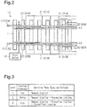
Fig. 2 is a schematic diagram showing a track junction on which the snow remover of the first embodiment is installed; -
Fig. 3 is a table showing operation modes of the snow remover of the first embodiment; -
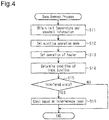
Fig. 4 is a flowchart showing a snow removal process performed by the snow remover of the first embodiment; -
Fig. 5 is a flowchart showing a non-switching process performed by the snow remover of the first embodiment; and -
Fig. 6 is a schematic block diagram showing a snow remover of a second embodiment. - A snow remover of a first embodiment will now be described with reference to
Figs. 1 to 5 . - In a snowy region, as shown in
Fig. 1 , asnow removal system 1, which corresponds to a snow remover, is installed on a track junction 10 (refer toFig. 2 ). Thesnow removal system 1 includes anejection device 2 that ejects a fluid to remove snow from thetrack junction 10 and aheating device 3 that heats rails of thetrack junction 10. In this description, snow includes, in addition to snow, ice formed from snow that has melted and frozen. Theejection device 2 corresponds to an ejector. - As shown in
Fig. 2 , thetrack junction 10 has the functions of dividing a track into tracks and switching between the tracks. Thetrack junction 10 includes twostock rails 12 fixed torailway sleepers 11, twotongue rails 13 moved relative to thestock rails 12, and apoint switch 14 that moves thetongue rails 13. When thepoint switch 14 moves thetongue rails 13, thetrack junction 10 switches the track. Thepoint switch 14 is of an electric type and moves thetongue rails 13 with a motor. In thetrack junction 10, when a train travels on thetrack junction 10 shifting between thestock rails 12 and thetongue rails 13, vibration is generated and causes snow to fall from under a floor of the train. The snow collected under the floor of the train includes hard snow. When an object such as snow is present between thestock rails 12 and thetongue rails 13, thetrack junction 10 may not be able to switch the track. This is referred to as a non-switching. - The
ejection device 2 is pneumatic and ejects compressed air as a fluid to blow snow away from between thestock rails 12 and thetongue rails 13 of thetrack junction 10. Theejection device 2 includespipes 21 arranged on a side surface of eachstock rail 12 and anair nozzle 22 arranged on the distal end of eachpipe 21. Theair nozzle 22 has an opening arranged between thestock rail 12 and thetongue rail 13 when thestock rail 12 is in close contact with thetongue rail 13. The opening of theair nozzles 22 is directed toward the distal end of thetongue rail 13 to blow snow toward the distal end of thetongue rail 13. A plurality of sets of thepipes 21 and theair nozzles 22 is arranged on thestock rails 12. - The
heating device 3 includesheaters 31 of an electric heating type. Theheaters 31 are arranged on a side surface of eachstock rail 12 and heat thestock rails 12 to melt snow and ice. Thetongue rails 13 may be heated in addition to or instead of thestock rails 12. Additionally, a panel heater may be arranged between therailway sleepers 11 to heat thestock rails 12 and/or thetongue rails 13. Theheaters 31 are not limited to the electric heating type and may be of a gas type. - As shown in
Fig. 1 , in theejection device 2, the twostock rails 12 include a normalside stock rail 12A and a reverseside stock rail 12B. Afirst pipe 21A is arranged on a side surface of the normalside stock rail 12A, and asecond pipe 21B is arranged on a side surface of the reverseside stock rail 12B. Afirst air nozzle 22A is arranged on the distal end of thefirst pipe 21A. A firstelectromagnetic valve 24A is arranged on thefirst pipe 21A to control ejection of air from thefirst air nozzle 22A. Asecond air nozzle 22B is arranged on the distal end of thesecond pipe 21B. A secondelectromagnetic valve 24B is arranged on thesecond pipe 21B to control ejection of air from thesecond air nozzle 22B. The firstelectromagnetic valve 24A and the secondelectromagnetic valve 24B are connected to anair tank 25 that stores compressed air. Theair tank 25 is connected to a pipe that is divided and connected to the firstelectromagnetic valve 24A and the secondelectromagnetic valve 24B. Theair tank 25 includes apressure sensor 27 that detects the pressure of theair tank 25. When the pressure of theair tank 25 is less than or equal to a threshold value, acompressor 26 operates and supplies compressed air to theair tank 25. More specifically, the compressed air is supplied from thecompressor 26 and stored in theair tank 25. The air is ejected from thefirst air nozzle 22A and thesecond air nozzle 22B in accordance with activation and deactivation of the firstelectromagnetic valve 24A and the secondelectromagnetic valve 24B connected to theair tank 25. Theejection device 2 is configured to change the ejection pressure, the ejection frequency, and the ejection time. - The
ejection device 2 includes anejection control device 20 that controls the air ejection performed by theejection device 2. Theejection control device 20 includes a programmable logic controller (PLC), or a sequence control device, and operates in accordance with a dedicated program called a ladder program. The PLC includes a central processing unit (CPU) and a memory. Theejection control device 20 is connected to input devices such as thepressure sensor 27, apoint position sensor 41, atrain detection sensor 42, and asnowfall detection sensor 43. Theejection control device 20 is also connected to output devices such as the firstelectromagnetic valve 24A, the secondelectromagnetic valve 24B, and thecompressor 26. Theejection control device 20 controls the output devices as controlled devices through the ladder program. Theejection control device 20 controls the ejection pressure, the ejection frequency, and the ejection time of air ejected from theejection device 2 by controlling activation and deactivation of the firstelectromagnetic valve 24A and the secondelectromagnetic valve 24B. Theejection control device 20 corresponds to a controller. - The
heating device 3 includes afirst heater 31A installed on the side surface of the normalside stock rail 12A of the twostock rails 12 in the extension direction thereof and asecond heater 31B installed on the side surface of the reverseside stock rail 12B in the extension direction thereof. Theheating device 3 further includes afirst temperature sensor 32A arranged on the normalside stock rail 12A to detect the temperature of the normalside stock rail 12A and asecond temperature sensor 32B arranged on the reverseside stock rail 12B to detect the temperature of the reverseside stock rail 12B. Thefirst temperature sensor 32A and thesecond temperature sensor 32B output temperature signals including the detected temperature information. As long as thefirst temperature sensor 32A and thesecond temperature sensor 32B are components of thesnow removal system 1, thefirst temperature sensor 32A and thesecond temperature sensor 32B do not have to be components of theheating device 3 and may be components of theejection device 2. Theejection control device 20 includes aninformation obtainer 20B that receives temperature signals from thefirst temperature sensor 32A and thesecond temperature sensor 32B to obtain the temperature information. - The
heating device 3 includes aheating control device 30 that controls heating performed by theheating device 3. Theheating control device 30 includes a programmable logic controller (PLC), or a sequence control device, and operates in accordance with a dedicated program called a ladder program. The PLC includes a CPU and a memory. Theheating control device 30 is connected to input devices such as thefirst temperature sensor 32A and thesecond temperature sensor 32B. Theheating control device 30 is also connected to output devices such as thefirst heater 31A and thesecond heater 31B. Theheating control device 30 controls the output devices as controlled devices through the ladder program. Theheating control device 30 controls the heating performed by theheating device 3 by controlling activation and deactivation of thefirst heater 31A and thesecond heater 31B. - The
point position sensor 41 detects positions of the tongue rails 13 between the normal and reverse side stock rails 12 based on a current value of the motor of thepoint switch 14 and outputs a position signal including the detected position information. Theejection control device 20 determines whether or not the track is switched based on the position signal received from thepoint position sensor 41. For example, when snow or ice is present between the stock rails 12 and the tongue rails 13 and the tongue rails 13 cannot move, thepoint position sensor 41 outputs a signal including position information indicating so. When non-switching occurs in thetrack junction 10, the switching of the track is retried or a switching signal including non-switching information is transmitted to, for example, an operation command site. - The
train detection sensor 42 includes, for example, an ultrasonic sensor and outputs a train passing detection signal when detecting that a train passes. - The
snowfall detection sensor 43 is arranged on or around thetrack junction 10 and detects an amount of snowfall based on an amount of moisture of snow collected on a detection portion and outputs a snowfall signal including the detected snowfall amount. Thesnowfall detection sensor 43 is not limited to a moisture detection type and may be of an infrared ray type that detects the amount of snowfall by detecting an infrared ray reflected by snow. The information obtainer 20B receives the snowfall signal from thesnowfall detection sensor 43 and obtains information of the amount of snowfall. The information obtainer 20B may obtain the amount of snow accumulation on or around thetrack junction 10 in addition to the amount of snowfall on or around thetrack junction 10. The amount of snowfall is an amount of snow that falls in a predetermined period of time and indicates how much it is currently snowing. The amount of snow accumulation is an amount of accumulated snow and indicates how much snow is currently accumulated. - As shown in
Fig. 3 , theejection control device 20 performs "removal ejection", "prevention ejection", and "intermittent ejection" with theejection device 2. The removal ejection refers to an air ejection performed by theejection device 2 to remove snow and ice from thetrack junction 10 when thetrack junction 10 is in a non-switching state. When thetrack junction 10 is in the non-switching state and the switching of the track is retried, retrying ejection is performed in which air is ejected whenever the retrying is performed. The prevention ejection refers to an air ejection performed by theejection device 2 whenever a train passes to prevent occurrence of the non-switching caused by snow falling from the traveling train on thetrack junction 10. The intermittent ejection refers to an air ejection performed by theejection device 2 at a fixed time interval during snowfall to avoid snow accumulation. - The
ejection control device 20 sets an operation mode of theejection device 2 in accordance with the temperature of the rail and snowfall information. More specifically, one operation mode is selected from a plurality of operation modes (ejection patterns) including appropriate combinations of "the removal ejection", "the prevention ejection", and "the intermittent ejection" and executed. In the operation mode of a first level, theejection control device 20 performs only the removal ejection so that the frequency of air ejection performed by theejection device 2 is decreased. When the temperature of the stock rails 12 is relatively high and there is no snowfall, theejection control device 20 sets the operation mode of the first level. In the operation mode of a second level, theejection control device 20 performs the removal ejection and the prevention ejection so that the frequency of air ejection performed by theejection device 2 is a medium level. When the temperature of the stock rails 12 is relatively low or there is snowfall, theejection control device 20 sets the operation mode of the second level. In the operation mode of a third level, theejection control device 20 performs the removal ejection, the prevention ejection, and the intermittent ejection so that the frequency of air ejection performed by theejection device 2 is increased. When the temperature of the stock rails 12 is relatively low and there is snowfall, theejection control device 20 sets the operation mode of the third level. The air ejection pattern in the operation mode of each level may be changed in any manner, for example, in accordance with the installation environment of thesnow removal system 1 and the train condition. - As shown in
Fig. 2 , theejection control device 20 does not simultaneously eject air from thefirst air nozzle 22A and thesecond air nozzle 22B but ejects air from one of thefirst air nozzle 22A and thesecond air nozzle 22B. Theejection control device 20 performs activation control to open the firstelectromagnetic valve 24A or the secondelectromagnetic valve 24B so that the compressed air is supplied to thepipes 21 located on the side surface of eachstock rail 12 located further from thetongue rail 13. As described above, when air is ejected from only one of thefirst air nozzle 22A and thesecond air nozzle 22B, a necessary air pressure or a necessary amount of air is reduced. If thefirst air nozzle 22A and thesecond air nozzle 22B simultaneously need to eject air, the air pressure of theair tank 25 or the amount of air in theair tank 25 may be set to the necessary pressure or the necessary amount. When the pressure value of theair tank 25 obtained from thepressure sensor 27 is less than or equal to a threshold value, theejection control device 20 operates thecompressor 26 to supply compressed air to theair tank 25. - As shown in
Fig. 1 , in components of theejection device 2, the firstelectromagnetic valve 24A, the secondelectromagnetic valve 24B, theair tank 25, thecompressor 26, thepressure sensor 27, and theejection control device 20 configure anair supply unit 23. When connected to a device arranged on thetrack junction 10, theair supply unit 23 serves as theejection device 2. Examples of devices arranged on thetrack junction 10 include thefirst pipe 21A, thefirst air nozzle 22A, thesecond pipe 21B, thesecond air nozzle 22B, thepoint position sensor 41, thetrain detection sensor 42, and thesnowfall detection sensor 43. Further, when connected to theheating control device 30 connected to the components of theheating device 3, namely thefirst heater 31A, thesecond heater 31B, thefirst temperature sensor 32A, and thesecond temperature sensor 32B, theair supply unit 23 serves as theheating device 3 in addition to theejection device 2. Theejection control device 20 of theair supply unit 23 may control theejection device 2 and theheating device 3. - The
ejection control device 20 and theheating control device 30 are connected to perform communication with each other by aconnection line 100, which corresponds to a communication portion. Theinformation obtainer 20B of theejection control device 20 obtains the temperature of the rails from theheating control device 30 through theconnection line 100. Theheating control device 30 obtains snowfall information and non-switching information from theejection control device 20 through theconnection line 100. Theejection control device 20 and theheating control device 30 may each include a communication portion allowing wireless communication instead of using theconnection line 100. - The
ejection control device 20 controls theheating device 3. More specifically, theejection control device 20 gives an instruction to theheating control device 30 of theheating device 3 to control theheating device 3 via theheating control device 30. - The
ejection control device 20 controls theejection device 2 and theheating device 3 based on the temperature of the rails of thetrack junction 10 and the snowfall information. More specifically, when the temperature of the stock rails 12 is relatively high and is, for example, greater than or equal to 5°C and there is snowfall, the snow may easily melt. When the temperature of the stock rails 12 is relatively low and is, for example, less than 5°C and there is snowfall, the snow may not melt and may accumulate. Thus, theejection control device 20 controls theejection device 2 and theheating device 3 based on the temperature of the stock rails 12 so that thesnow removal system 1 effectively operates while limiting occurrence of the non-switching of thetrack junction 10. - The
ejection control device 20 controls the operation of theejection device 2 based on the amount of snowfall on thetrack junction 10. Theejection control device 20 includes adetermination unit 20A determining whether or not movement of thetrack junction 10 is in a state interfered with by snow present in thetrack junction 10. When thedetermination unit 20A determines that movement of thetrack junction 10 is in the state interfered with by snow, theejection control device 20 operates theejection device 2. - The
ejection control device 20 is connected to a camera 51 that captures an image of thetrack junction 10, anelectrical conductivity sensor 52 that detects the electrical conductivity of the stock rails 12 of thetrack junction 10, and avibration sensor 53 that detects vibration of the stock rails 12 of thetrack junction 10. The camera 51 sends image information, which is obtained by capturing an image of thetrack junction 10, to theejection control device 20. Theelectrical conductivity sensor 52 sends measurement information, which is obtained by measuring the electrical conductivity of the rails of thetrack junction 10, to theejection control device 20. Thevibration sensor 53 sends measurement information, which is obtained by measuring vibration of the stock rails 12 of thetrack junction 10, to theejection control device 20. Only at least one of the camera 51, theelectrical conductivity sensor 52, and thevibration sensor 53 may be connected to theejection control device 20. That is, at least one of the camera 51, theelectrical conductivity sensor 52, and thevibration sensor 53 may be omitted. - The
ejection control device 20 recognizes the condition of thetrack junction 10 based on information received from at least one of the camera 51, theelectrical conductivity sensor 52, thevibration sensor 53, and theheating control device 30. When snow is present in thetrack junction 10, the electrical conductivity and vibration of the rails vary. Thedetermination unit 20A determines whether or not snow is present in thetrack junction 10 based on at least one of a captured image of thetrack junction 10, vibration of the stock rails 12 of thetrack junction 10, the electrical conductivity of the stock rails 12 of thetrack junction 10, and an operation condition of theheating device 3. - The
determination unit 20A also determines whether or not movement of thetrack junction 10 is in a state interfered with by snow based on at least one of a captured image of thetrack junction 10, vibration of the stock rails 12 of thetrack junction 10, the electrical conductivity of the stock rails 12 of thetrack junction 10, and an operation condition of theheating device 3. When thedetermination unit 20A determines that movement of thetrack junction 10 is in the state interfered with by snow, thedetermination unit 20A further determines the level of interference with thetrack junction 10, for example, whether it takes a long time for recovery due to interference of a large amount of snow or it takes a short time for recovery due to interference of a small amount of snow. Theejection control device 20 changes the operation mode of theejection device 2 in accordance with the level of interference determined by thedetermination unit 20A. - The operation of the
snow removal system 1 that is configured as described above will now be described with reference toFigs. 4 and5 . - As shown in
Fig. 4 , theejection control device 20 performs a snow removal process described below. - The
information obtainer 20B of theejection control device 20 obtains the temperature of the rails of thetrack junction 10 and the snowfall information (step S11). More specifically, theinformation obtainer 20B of theejection control device 20 obtains the temperature of the normalside stock rail 12A from a temperature signal output from thefirst temperature sensor 32A and the temperature of the reverseside stock rail 12B from a temperature signal output from thesecond temperature sensor 32B. Theinformation obtainer 20B of theejection control device 20 also obtains the snowfall information from a snowfall signal output from thesnowfall detection sensor 43. - Subsequently, the
ejection control device 20 sets the ejecting operation mode (step S12). More specifically, theejection control device 20 selects one from the operation modes of theejection device 2 based on the obtained temperature of the stock rails 12 and the obtained snowfall information. More specifically, when the temperature of the stock rails 12 is, for example, greater than or equal to 5°C and there is no snowfall, theejection control device 20 sets the operation mode of the first level. In the operation mode of the first level, theejection control device 20 performs only the removal ejection. When the temperature of the stock rails 12 is less than 5°C or there is snowfall, theejection control device 20 sets the operation mode of the second level. In the operation mode of the second level, theejection control device 20 performs the removal ejection and the prevention ejection. When the temperature of the stock rails 12 is less than 5°C and there is snowfall, theejection control device 20 sets the operation mode of the third level. In the operation mode of the third level, theejection control device 20 performs the removal ejection, the prevention ejection, and the intermittent ejection. - Subsequently, the
ejection control device 20 sets the operation of the heaters (step S13). More specifically, theejection control device 20 causes theheating control device 30 to set the operation of thefirst heater 31A and thesecond heater 31B taking into consideration the operation condition of theejection device 2. Thus, theheaters 31 are operated at lower temperatures than those operated in a typical manner. For example, in a typical configuration in which an ejection device and a heating device are separately operated, activation control is performed on heaters of the heating device at less than 5°C, and deactivation control is performed on the heaters at 15°C or greater. In the present embodiment, activation control may be set to be performed on thefirst heater 31A and thesecond heater 31B of theheating device 3 of thesnow removal system 1 at less than 3°C, and deactivation control may be set to be performed at 10°C or greater. This is because theheating device 3 heats the stock rails 12 so that snow and ice are easy to separate and blown away by air of theejection device 2. This eliminates the need for entirely melting snow and ice present in thetrack junction 10. - Subsequently, the
ejection control device 20 determines the condition of the track junction 10 (step S14). More specifically, thedetermination unit 20A determines whether or not movement of thetrack junction 10 is in a state interfered with by snow based on at least one of a captured image of thetrack junction 10, vibration of the rails of thetrack junction 10, the electrical conductivity of the rails of thetrack junction 10, and the operation condition of theheating device 3. - When the
determination unit 20A determines that movement of thetrack junction 10 is not in a state interfered with by snow (step S15: NO), theejection control device 20 causes theejection device 2 to eject air in the operation mode that is set in step S12 and causes theheating device 3 to operate theheaters 31 in the operation mode that is set in step S13. - When the
determination unit 20A determines that movement of thetrack junction 10 is in a state interfered with by snow (step S15: YES), theejection control device 20 causes theejection device 2 to eject air in accordance with the level of interference with the track junction 10 (step S16). For example, when thedetermination unit 20A determines that a large amount of snow interferes with thetrack junction 10, theejection control device 20 causes theejection device 2 to eject air for a first predetermined amount of time, at a first predetermined frequency, or at a first predetermined pressure regardless of the operation mode. When thedetermination unit 20A determines that a small amount of snow interferes with thetrack junction 10, theejection control device 20 causes theejection device 2 to eject air for a second predetermined amount of time that is less than the first predetermined amount of time, a second predetermined frequency that is less than the first predetermined frequency, or at a second predetermined pressure that is less than the first predetermined pressure regardless of the operation mode. - As shown in
Fig. 5 , when the non-switching occurs in thetrack junction 10, theejection control device 20 performs a non-switching process in the snow removal process. When the non-switching occurs, theejection control device 20 causes theejection device 2 to perform the removal ejection whenever thepoint switch 14 operates to switch the track. Occurrence of non-switching may be determined together with the determination of the condition of thetrack junction 10 performed in step S14, that is, the determination of whether or not movement of thetrack junction 10 is in a state interfered with by snow. Then, the following process may be performed. - The
ejection control device 20 determines whether or not the heaters are activated (step S21). More specifically, when occurrence of non-switching is caused by the presence of snow or ice on thetrack junction 10, the non-switching may be eliminated by heating the stock rails 12. Thus, theejection control device 20 determines whether or not activation control is performed on thefirst heater 31A and thesecond heater 31B. When theejection control device 20 determines that deactivation control is performed on thefirst heater 31A and thesecond heater 31B (step S21: NO), the heaters are activated (step S25). More specifically, theejection control device 20 forcibly performs activation control on thefirst heater 31A and thesecond heater 31B to heat the stock rails 12 regardless of the operation mode of theejection device 2. - When the
ejection control device 20 determines that activation control is performed on thefirst heater 31A and thesecond heater 31B (step S21: YES), theejection control device 20 continues to perform the activation control on thefirst heater 31A and thesecond heater 31B (step S22). - Subsequently, the
ejection control device 20 determines whether or not thetrack junction 10 is in the non-switching state (step S23). More specifically, theejection control device 20 determines whether or not the non-switching state is eliminated from thetrack junction 10. When theejection control device 20 determines that thetrack junction 10 is not in the non-switching state (step S23: NO), the non-switching is eliminated. Thus, the non-switching process is ended. - When the
ejection control device 20 determines that thetrack junction 10 is in the non-switching state (step S23: YES), the non-switching is not eliminated. Thus, theejection control device 20 determines whether or not a predetermined amount of time has elapsed from when the non-switching process was started (step S24). A certain amount of time is needed to warm the stock rails 12 with thefirst heater 31A and thesecond heater 31B. Thus, when theejection control device 20 determines that the predetermined amount of time has not elapsed (step S24: NO), theejection control device 20 proceeds to step S23 to wait until the predetermined amount of time elapses. - When the
ejection control device 20 determines that the predetermined amount of time has elapsed (step S24: YES), the non-switching cannot be eliminated by the heating of the stock rails 12 for the predetermined amount of time. Thus, the non-switching process is ended. Theejection control device 20 informs, for example, the operation command site that the non-switching cannot be eliminated. - As described above, the
ejection control device 20 controls the operation of theejection device 2 based on the condition of thetrack junction 10. Thus, an object such as snow may be removed before the non-switching occurs in thetrack junction 10, and theejection device 2 is effectively operated. - As described above, the present embodiment has the advantages described below.
- (1) The
ejection device 2 is controlled based on the condition of thetrack junction 10. Thus, theejection device 2 is effectively operated. - (2) When it is determined that movement of the
track junction 10 is in a state interfered with by snow, theejection device 2 is operated. Thus, unnecessary operation of theejection device 2 is reduced. - (3) The operation mode of the
ejection device 2 is changed in accordance with the level of interference with thetrack junction 10. Thus, unnecessary operation of theejection device 2 is reduced as compared to when theejection device 2 is operated based on only whether or not movement of thetrack junction 10 is in the interfered state. - (4) The control of the
ejection device 2 and the control of theheating device 3 are combined and performed based on the condition of thetrack junction 10. Thus, thesnow removal system 1 is effectively operated. - A snow remover of a second embodiment will now be described with reference to
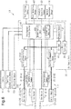
Fig. 6 . The snow remover of the second embodiment differs from that of the first embodiment in that the snow remover includes a control device that controls both an ejection device and a heating device. The description hereafter will focus on the differences from the first embodiment. - As shown in
Fig. 6 , thesnow removal system 101 includes anejection device 102, aheating device 103, and a snowremoval control device 40 that controls both theejection device 102 and theheating device 103. Theheating device 103 does not include a control device and is controlled by the snowremoval control device 40. The snowremoval control device 40 performs control in the same manner as theejection control device 20 of the first embodiment and directly controls theheaters 31. The snowremoval control device 40 performs activation and deactivation control on the firstelectromagnetic valve 24A and the secondelectromagnetic valve 24B of theejection device 102 to control the air ejection performed by theejection device 102. The snowremoval control device 40 performs activation and deactivation control on thefirst heater 31A and thesecond heater 31B of theheating device 103 to control the heating performed by theheating device 103. The snowremoval control device 40 corresponds to a controller. - The snow
removal control device 40 includes a programmable logic controller (PLC), or a sequence control device, and operates in accordance with a dedicated program called a ladder program. The PLC includes a CPU and a memory. The snowremoval control device 40 is connected to input devices such as thepressure sensor 27, thefirst temperature sensor 32A, thesecond temperature sensor 32B, thepoint position sensor 41, thetrain detection sensor 42, and thesnowfall detection sensor 43. The snowremoval control device 40 is also connected to output devices such as the firstelectromagnetic valve 24A, the secondelectromagnetic valve 24B, thecompressor 26, thefirst heater 31A, and thesecond heater 31B. The snowremoval control device 40 controls the output devices as controlled devices through the ladder program. - The snow
removal control device 40 controls the operation of theejection device 2 based on information of an amount of snow accumulation on thetrack junction 10. The snowremoval control device 40 includes adetermination unit 40A that determines whether or not movement of thetrack junction 10 is in a state interfered with by snow present in thetrack junction 10. When thedetermination unit 40A determines that movement of thetrack junction 10 is in the state interfered with by snow, the snowremoval control device 40 operates theejection device 102. The snowremoval control device 40 includes aninformation obtainer 40B that obtains various kinds of information. - The snow
removal control device 40 is connected to the camera 51 that captures an image of thetrack junction 10, theelectrical conductivity sensor 52 that detects the electrical conductivity of the stock rails 12 of thetrack junction 10, and thevibration sensor 53 that detects vibration of the stock rails 12 of thetrack junction 10. Only at least one of the camera 51, theelectrical conductivity sensor 52, and thevibration sensor 53 may be connected to the snowremoval control device 40. That is, at least one of the camera 51, theelectrical conductivity sensor 52, and thevibration sensor 53 may be omitted. - The snow
removal control device 40 recognizes the condition of thetrack junction 10 based on information from at least one of the camera 51, theelectrical conductivity sensor 52, thevibration sensor 53, and theheating control device 30. When snow is present in thetrack junction 10, the electrical conductivity and vibration properties of the rails vary. Thedetermination unit 40A determines whether or not snow is present in thetrack junction 10 based on at least one of a captured image of thetrack junction 10, vibration of the stock rails 12 of thetrack junction 10, the electrical conductivity of the stock rails 12 of thetrack junction 10, and the operation condition of theheating device 3. - The
determination unit 40A also determines whether or not movement of thetrack junction 10 is in a state interfered with by snow based on at least one of a captured image of thetrack junction 10, vibration of the stock rails 12 of thetrack junction 10, the electrical conductivity of the stock rails 12 of thetrack junction 10, and the operation condition of theheating device 3. When thedetermination unit 40A determines that movement of thetrack junction 1 0 is in the state interfered with by snow, thedetermination unit 40A further determines the level of interference with thetrack junction 10, for example, whether it takes a long time for recovery due to interference of a large amount of snow or it takes a short time for recovery due to interference of a small amount of snow. The snowremoval control device 40 changes the operation mode of theejection device 2 in accordance with the level of interference determined by thedetermination unit 40A. - As described above, the present embodiment has the advantages described below in addition to advantages (1) to (4) of the first embodiment.
(5) The snowremoval control device 40, which corresponds to a control device of theejection device 102, directly controls theheaters 31. This eliminates the need for a control device of theheating device 103 and simplifies the configuration. - The embodiments may be modified as follows.
- In the snow removal process of each embodiment, the step of setting the ejecting operation mode (step S12) and the step of setting the operation of the heaters 31 (step S13) may be switched in order or may be simultaneously executed.
- In the snow removal process of each embodiment, the ejecting operation mode and the operation of the heaters 31 (step S11 to S13) are set based on the temperature of the rails and the information of a snowfall amount. Instead, the ejecting operation mode and the operation of the heaters may be set based on determination of the condition of the track junction 10 (step S14).
- In each embodiment, the
information obtainer 20B may obtain information of an amount of snow accumulation. At least one of the ejection pressure, the ejection frequency, and the ejection time of air ejected from theejection devices - In each embodiment, the
snowfall detection sensor 43 may be omitted when the presence of snow in thetrack junction 10, the amount of snowfall, and the amount of snow accumulation are determined based on information from at least one of the camera 51, theelectrical conductivity sensor 52, thevibration sensor 53, and theheating control device 30,. - In the snow removal process of each embodiment, the step of causing the
ejection device 2 to eject air in accordance with the level of interference with the track junction 10 (step S16) may be changed to a step of causing theejection device 2 to eject air regardless of the interference level. - In the first embodiment, the
ejection control device 20 controls theheating device 3. However, theejection control device 20 does not necessarily have to control theheating device 3. More specifically, theheating control device 30 may control theheating device 3 based on the temperature of the rails. - In each embodiment, control is performed based on the temperature of the stock rails 12. Instead, control may be performed based on the temperature of the tongue rails 13. Further, control may be performed based on both the temperature of the stock rails 12 and the temperature of the tongue rails 13. For example, the temperature of the stock rails 12 may be compared with the temperature of the tongue rails 13, and control may be performed based on the lower one of the temperatures.
- In each embodiment, the operation mode is set based on the temperature of the rails of the
track junction 10 and the information of a snowfall amount. Instead, the operation mode may be set based on only the information of a snowfall amount. For example, theejection control device 20 sets the operation mode of the first level when the amount of snowfall is 0 cm/hour, the operation mode of the second level when the amount of snowfall is less than 3 cm/hour, and the operation mode of the third level when the amount of snowfall is greater than or equal to 3 cm/hour. - In each of the configurations described above, as shown in
Figs. 1 and6 , thesnow removal systems ambient temperature sensor 44 that detects the ambient temperature around thetrack junction 10 and outputs an ambient temperature signal including ambient temperature information. The snowremoval control device 40 and theheating control device 30 may perform activation and deactivation control on thefirst heater 31A and thesecond heater 31 B based on the ambient temperature instead of the temperature of the rails. In this configuration, when snow is present in thetrack junction 10, the snow is quickly removed by operating at least one of theejection devices heating devices - In the embodiments, the
ejection devices track junction 10 on which theejection devices ejection devices track junction 10 is installed or information related to at least one of the amount of snow accumulation and the amount of snowfall around another track junction installed ahead or behind on the same track. - In the first embodiment, the
ejection control device 20 and theheating control device 30 are PLCs. However, theejection control device 20 and theheating control device 30 are not limited to PLCs and may be devices that control controlled devices without using the ladder program. - In the second embodiment, the snow
removal control device 40 is a PLC. However, the snowremoval control device 40 is not limited to a PLC and may be a device that controls controlled devices without using the ladder program. - In the embodiments, the
ejection devices track junction 10 is in the non-switching state, heat is applied between the stock rails 12 and the tongue rails 13. - The fluid ejected by the
ejection devices - It should be apparent to those skilled in the art that the present invention may be embodied in many other specific forms without departing from the scope of the invention. For example, one or more of the components may be omitted from the components described in the embodiments (or one or more aspects thereof). Further, components in different embodiments may be appropriately combined.
- The present examples and embodiments are to be considered as illustrative and not restrictive, and the invention is not to be limited to the details given herein, but may be modified within the scope and equivalence of the appended claims.
Claims (5)
- A snow remover (1; 101) comprising:an ejector (2; 102) that ejects a fluid to remove snow from a track junction (10);an information obtainer (20B, 40B) that obtains information related to at least one of an amount of snow accumulation and an amount of snowfall around the track junction (10); anda controller (20; 40) that controls at least one of an ejection pressure, an ejection frequency, and an ejection time of the fluid ejected from the ejector (2; 102) in accordance with information obtained by the information obtainer (20B; 40B).
- The snow remover (1; 101) according to claim 1, wherein
the controller (20; 40) includes a determination unit (20A; 40A) that determines whether or not movement of the track junction (10) is in a state interfered with by snow present in the track junction (10), and
when the determination unit (20A; 40A) determines that movement of the track junction (10) is in a state interfered with by snow, the controller (20; 40) operates the ejector (2; 102). - The snow remover (1; 101) according to claim 2, wherein the determination unit (20A; 40A) determines whether or not movement of the track junction (10) is in a state interfered with by snow based on at least one of a captured image of the track junction (10), vibration of a rail (12) included in the track junction (10), an electrical conductivity of the rail (12), and an operation condition of a heating device (3; 103) that heats the rail (12).
- The snow remover (1; 101) according to claim 2 or 3, wherein
when the determination unit (20A; 40A) determines that movement of the track junction (10) is in a state interfered with by snow, the determination unit (20A; 40A) further determines a level of interference with the track junction (10), and
the ejector (2; 102) is operated in an operation mode changed by the controller in accordance with the level of interference determined by the determination unit (20A; 40A). - The snow remover (1; 101) according to any one of claims 1 to 4, further comprising a heating device (3; 103) that heats a rail (12) included in the track junction (10), wherein the controller (20; 40) further controls the heating device (3; 103).
Applications Claiming Priority (1)
| Application Number | Priority Date | Filing Date | Title |
|---|---|---|---|
| JP2018060561A JP2019173326A (en) | 2018-03-27 | 2018-03-27 | Snow removal device |
Publications (1)
| Publication Number | Publication Date |
|---|---|
| EP3546647A1 true EP3546647A1 (en) | 2019-10-02 |
Family
ID=65766886
Family Applications (1)
| Application Number | Title | Priority Date | Filing Date |
|---|---|---|---|
| EP19162116.8A Pending EP3546647A1 (en) | 2018-03-27 | 2019-03-12 | Snow remover |
Country Status (2)
| Country | Link |
|---|---|
| EP (1) | EP3546647A1 (en) |
| JP (1) | JP2019173326A (en) |
Families Citing this family (1)
| Publication number | Priority date | Publication date | Assignee | Title |
|---|---|---|---|---|
| JP7419719B2 (en) | 2019-09-24 | 2024-01-23 | カシオ計算機株式会社 | Sleep stage estimation device, sleep stage estimation method and program |
Citations (4)
| Publication number | Priority date | Publication date | Assignee | Title |
|---|---|---|---|---|
| JPH06240606A (en) * | 1993-02-12 | 1994-08-30 | East Japan Railway Co | Device for removing foreign materials at junction of rail road |
| JPH06240605A (en) | 1993-02-12 | 1994-08-30 | East Japan Railway Co | Foreign matter removal device at track branch |
| EP2740844A1 (en) * | 2011-07-26 | 2014-06-11 | East Japan Railway Company | Foreign body removal device for branching track section and nozzle used therefor |
| EP2765239A1 (en) * | 2011-09-16 | 2014-08-13 | East Japan Railway Company | Foreign matter removal device for track branching section |
Family Cites Families (2)
| Publication number | Priority date | Publication date | Assignee | Title |
|---|---|---|---|---|
| JP3940505B2 (en) * | 1998-11-05 | 2007-07-04 | 東海旅客鉄道株式会社 | Snow melting equipment |
| EP3059345B1 (en) * | 2013-10-03 | 2022-07-13 | East Japan Railway Company | Foreign matter removal system for track branch parts |
-
2018
- 2018-03-27 JP JP2018060561A patent/JP2019173326A/en active Pending
-
2019
- 2019-03-12 EP EP19162116.8A patent/EP3546647A1/en active Pending
Patent Citations (4)
| Publication number | Priority date | Publication date | Assignee | Title |
|---|---|---|---|---|
| JPH06240606A (en) * | 1993-02-12 | 1994-08-30 | East Japan Railway Co | Device for removing foreign materials at junction of rail road |
| JPH06240605A (en) | 1993-02-12 | 1994-08-30 | East Japan Railway Co | Foreign matter removal device at track branch |
| EP2740844A1 (en) * | 2011-07-26 | 2014-06-11 | East Japan Railway Company | Foreign body removal device for branching track section and nozzle used therefor |
| EP2765239A1 (en) * | 2011-09-16 | 2014-08-13 | East Japan Railway Company | Foreign matter removal device for track branching section |
Also Published As
| Publication number | Publication date |
|---|---|
| JP2019173326A (en) | 2019-10-10 |
Similar Documents
| Publication | Publication Date | Title |
|---|---|---|
| EP2695758B1 (en) | Air conditioner for vehicle | |
| CN107635820B (en) | Charging device and method for operating a charging device | |
| EP3564442B1 (en) | Monitoring system for foreign substance removal device and monitoring method for foreign substance removal device | |
| EP3546648A1 (en) | Controller for snow removal system, ejection controller, and heating controller | |
| US20070261424A1 (en) | Cooling device and controlling method thereof for reefer container | |
| JP6093024B2 (en) | Foreign matter removal system for track branch and foreign matter removal device for track branch | |
| CN202947396U (en) | Defrosting device and heat control equipment | |
| CN104736767A (en) | Method for checking the serviceability of point heaters of a rail network | |
| KR20170100381A (en) | System for protecting railload switching portion | |
| JP2019173326A (en) | Snow removal device | |
| JP4952623B2 (en) | Car wash equipment | |
| EP3797998B1 (en) | Ejection device | |
| KR101792709B1 (en) | Ground temperature sensor, snow melting system with the same and the control method thereof | |
| KR20120001838A (en) | Railroad turn off snow melting device using heat pipe | |
| KR100358407B1 (en) | Electric Heating Device for Switch Points | |
| JP4254632B2 (en) | Snow melting equipment | |
| RU2680926C1 (en) | Railway train and air conditioner control system | |
| KR20100036518A (en) | An apparatus for controlling the temperature of washer liquid for vehicle | |
| KR101221802B1 (en) | System for passing transfer switching section and the method for managing the system | |
| KR102588068B1 (en) | Window frost prevention system for vehicle | |
| KR100496205B1 (en) | An insulated auto controlled electric heating device for removal of ice and snow from the railroad point and remote central monitoring system thereof | |
| JP7544626B2 (en) | Control method for electric snow melting mat | |
| KR100942927B1 (en) | Wiper Controls and Methods | |
| KR20130120222A (en) | Method for preventing safety accident of water purifier and water purifier using the same | |
| KR101149098B1 (en) | Apparatus and method for sensible heat recovery of slag |
Legal Events
| Date | Code | Title | Description |
|---|---|---|---|
| PUAI | Public reference made under article 153(3) epc to a published international application that has entered the european phase |
Free format text: ORIGINAL CODE: 0009012 |
|
| STAA | Information on the status of an ep patent application or granted ep patent |
Free format text: STATUS: THE APPLICATION HAS BEEN PUBLISHED |
|
| AK | Designated contracting states |
Kind code of ref document: A1 Designated state(s): AL AT BE BG CH CY CZ DE DK EE ES FI FR GB GR HR HU IE IS IT LI LT LU LV MC MK MT NL NO PL PT RO RS SE SI SK SM TR |
|
| AX | Request for extension of the european patent |
Extension state: BA ME |
|
| STAA | Information on the status of an ep patent application or granted ep patent |
Free format text: STATUS: REQUEST FOR EXAMINATION WAS MADE |
|
| 17P | Request for examination filed |
Effective date: 20200325 |
|
| RBV | Designated contracting states (corrected) |
Designated state(s): AL AT BE BG CH CY CZ DE DK EE ES FI FR GB GR HR HU IE IS IT LI LT LU LV MC MK MT NL NO PL PT RO RS SE SI SK SM TR |
|
| STAA | Information on the status of an ep patent application or granted ep patent |
Free format text: STATUS: EXAMINATION IS IN PROGRESS |
|
| 17Q | First examination report despatched |
Effective date: 20210623 |
|
| P01 | Opt-out of the competence of the unified patent court (upc) registered |
Effective date: 20230523 |