EP3546631A1 - Flat knitting machine - Google Patents
Flat knitting machine Download PDFInfo
- Publication number
- EP3546631A1 EP3546631A1 EP19166016.6A EP19166016A EP3546631A1 EP 3546631 A1 EP3546631 A1 EP 3546631A1 EP 19166016 A EP19166016 A EP 19166016A EP 3546631 A1 EP3546631 A1 EP 3546631A1
- Authority
- EP
- European Patent Office
- Prior art keywords
- rail
- information
- optical wireless
- knitting machine
- yfs
- Prior art date
- Legal status (The legal status is an assumption and is not a legal conclusion. Google has not performed a legal analysis and makes no representation as to the accuracy of the status listed.)
- Granted
Links
Images


Classifications
-
- D—TEXTILES; PAPER
- D04—BRAIDING; LACE-MAKING; KNITTING; TRIMMINGS; NON-WOVEN FABRICS
- D04B—KNITTING
- D04B15/00—Details of, or auxiliary devices incorporated in, weft knitting machines, restricted to machines of this kind
- D04B15/66—Devices for determining or controlling patterns ; Program-control arrangements
- D04B15/68—Devices for determining or controlling patterns ; Program-control arrangements characterised by the knitting instruments used
- D04B15/70—Devices for determining or controlling patterns ; Program-control arrangements characterised by the knitting instruments used in flat-bed knitting machines
-
- D—TEXTILES; PAPER
- D04—BRAIDING; LACE-MAKING; KNITTING; TRIMMINGS; NON-WOVEN FABRICS
- D04B—KNITTING
- D04B15/00—Details of, or auxiliary devices incorporated in, weft knitting machines, restricted to machines of this kind
- D04B15/38—Devices for supplying, feeding, or guiding threads to needles
- D04B15/44—Tensioning devices for individual threads
-
- D—TEXTILES; PAPER
- D04—BRAIDING; LACE-MAKING; KNITTING; TRIMMINGS; NON-WOVEN FABRICS
- D04B—KNITTING
- D04B15/00—Details of, or auxiliary devices incorporated in, weft knitting machines, restricted to machines of this kind
- D04B15/38—Devices for supplying, feeding, or guiding threads to needles
- D04B15/48—Thread-feeding devices
-
- D—TEXTILES; PAPER
- D04—BRAIDING; LACE-MAKING; KNITTING; TRIMMINGS; NON-WOVEN FABRICS
- D04B—KNITTING
- D04B15/00—Details of, or auxiliary devices incorporated in, weft knitting machines, restricted to machines of this kind
- D04B15/38—Devices for supplying, feeding, or guiding threads to needles
- D04B15/54—Thread guides
- D04B15/56—Thread guides for flat-bed knitting machines
-
- D—TEXTILES; PAPER
- D04—BRAIDING; LACE-MAKING; KNITTING; TRIMMINGS; NON-WOVEN FABRICS
- D04B—KNITTING
- D04B15/00—Details of, or auxiliary devices incorporated in, weft knitting machines, restricted to machines of this kind
- D04B15/66—Devices for determining or controlling patterns ; Program-control arrangements
- D04B15/68—Devices for determining or controlling patterns ; Program-control arrangements characterised by the knitting instruments used
- D04B15/78—Electrical devices
-
- D—TEXTILES; PAPER
- D04—BRAIDING; LACE-MAKING; KNITTING; TRIMMINGS; NON-WOVEN FABRICS
- D04B—KNITTING
- D04B15/00—Details of, or auxiliary devices incorporated in, weft knitting machines, restricted to machines of this kind
- D04B15/66—Devices for determining or controlling patterns ; Program-control arrangements
- D04B15/80—Devices for determining or controlling patterns ; Program-control arrangements characterised by the thread guides used
-
- D—TEXTILES; PAPER
- D04—BRAIDING; LACE-MAKING; KNITTING; TRIMMINGS; NON-WOVEN FABRICS
- D04B—KNITTING
- D04B7/00—Flat-bed knitting machines with independently-movable needles
- D04B7/02—Flat-bed knitting machines with independently-movable needles with one set of needles
-
- H—ELECTRICITY
- H04—ELECTRIC COMMUNICATION TECHNIQUE
- H04B—TRANSMISSION
- H04B10/00—Transmission systems employing electromagnetic waves other than radio-waves, e.g. infrared, visible or ultraviolet light, or employing corpuscular radiation, e.g. quantum communication
- H04B10/11—Arrangements specific to free-space transmission, i.e. transmission through air or vacuum
Definitions
- the present invention relates to a flat knitting machine.
- a flat knitting machine includes a needle bed in which multiple knitting needles are arranged side-by-side, and is provided with multiple moving bodies that are involved in the knitting of a knitted fabric, and these moving bodies are attached to a rail and travel along the rail.
- One example of such moving bodies is yarn feeders (hereinafter, sometimes called "YF") that feed yarn to the knitting needles in the needle bed.
- Patent Document 1 discloses a configuration in which a YF is driven by a linear motor, or a drive motor or the like is attached to a YF, such that the YF is self-propelled.
- the drive motor provided for the YF and the control apparatus for control thereof are supplied with electrical power through contact power supply that is performed via a contact strip provided on the rail.
- Patent Document 2 discloses a moving body (reference sign 300 in Patent Document 2) that travels on a rail to which the YF is attached, and that moves the YF by inserting a changeover pin into the YF.
- the insertion and removal of the changeover pin is performed using electrical power that is supplied to the moving body through contact between a conductive sheet provided on the rail and a carbon brush provided on the moving body.
- Patent Document 1 there has been a proposal to provide a YF with a device that operates electrically.
- information indicating a device operation timing and the like needs to be transmitted to the YF.
- Wireless transmission can be performed using Wi-Fi (registered trademark) or the like, but it is troublesome to create specifications that comply with radio laws in various countries.
- optical wireless communication which can be used regardless of radio laws, but unlike radio waves, information cannot be transmitted around obstacles, and therefore it is difficult to transmit information to each of the plurality of YFs provided in a flat knitting machine.
- YFs frequently change position when knitting a knitted fabric, and therefore if a YF or the like becomes located between an optical wireless transmitter and a target YF, information cannot be transmitted to the target YF.
- the present invention was achieved in light of the foregoing circumstances, and an object thereof is to provide a flat knitting machine in which information can be reliably transmitted to a target yarn feeder using optical wireless communication.
- a flat knitting machine of the present invention includes a needle bed having a plurality of knitting needles, a rail extending along a length direction of the needle bed, a plurality of yarn feeders provided on the rail, and a computer that controls the flat knitting machine, the flat knitting machine including:
- the optical wireless transceivers each include a YF side receiver that is provided on the yarn feeder at a position on one end side of the rail and has a light reception axis that is directed toward the one end side, and a YF side transmitter that is provided on the yarn feeder at a position on an other end side of the rail and has a light projection axis that is directed toward the other end side.
- the flat knitting machine further includes: a first feeder group made up of a plurality of the yarn feeders that travel on a same track; and a second feeder group made up of a plurality of the yarn feeders that travel on another track that is adjacent to the track on which the first feeder group travels, wherein a communication direction with respect to the first feeder group and a communication direction with respect to the second feeder group are opposite directions.
- the yarn feeders each include at least one electrical device that acquires knitting-related information in addition to the optical wireless transceiver, and the information acquired by the at least one electrical device is transmitted to the computer through optical wireless communication.
- knitting-related first information is transmitted from the main body side transmitter.
- Each YF relays, to the main body side receiver, knitting-related second information which includes further information successively added by each of the YFs to the first information.
- each YF may relay, to the main body side receiver, the first information as it is. Therefore, even if a plurality of YFs are provided on one track, information can be reliably transmitted to each of the YFs by performing optical wireless communication in which the information is successively relayed by the optical wireless transceivers provided on the YFs.
- the track is a YF traveling route formed on the rail.
- the YFs on that track travel back and forth on the same straight line.
- the YF located on one end side of the track cannot pass a YF on the other end side of that YF in order to travel toward the other end side.
- the YF side receiver is provided at a position on the one end side of the rail, and the YF side transmitter is provided at a position on the other end side of the rail, and therefore the YFs can easily receive information from the one end side and easily transmit information to the other end side, thus making it possible for information to be easily transmitted from the one end side of the rail to the other end side.
- the YFs arranged on the same track can have the same configuration.
- the YF side receiver is arranged on the other end side of each YF
- the YF side transmitter is arranged on the one end side of each YF
- YFs that are adjacent on the track need to have different configurations.
- One feeder group and another feeder group that are adjacent in the rail parallel arrangement direction are given opposite communication directions in optical wireless communication, thus making it possible to suppress the case where information is transmitted to the wrong YF.
- Information acquired by the electrical devices provided on the YFs is fed back to the computer, thus making it possible to improve knitting conditions and improve knitting efficiency.
- a flat knitting machine 1 according to an embodiment of the present invention will be described below with reference to FIGS. 1 to 5 .
- the flat knitting machine 1 includes a pair of needle beds 1B that are arranged facing each other in the depth direction with respect to the paper plane, and yarn feeders (hereinafter, called "YF") 2A to 2D that feed knitting yarn 9 to a needle bed gap formed between the two needle beds 1B.
- YF yarn feeders
- Multiple knitting needles are aligned in each needle bed 1B, and these knitting needles are driven by a cam system (not shown) provided in a carriage 1C that moves back and forth over the needle bed 1B.
- the YFs 2A to 2D travel along a rail 1R.
- the rail 1R spans between a pair of frames 1FR and 1FL, which are immovable members that are provided upright on respective end sides of the flat knitting machine 1 and are integrated with the flat knitting machine 1.
- Multiple rails 1R are provided parallel with each other in the depth direction with respect to the paper plane, and the rails 1R each extend parallel with the needle beds 1B at positions above the needle beds 1B.
- YFs 2 will be used instead of distinguishing between the YFs 2A to 2D.
- multiple YFs 2 are attached to each rail 1R.
- the YFs 2A and 2B are attached to the surface of the rail 1R that is on the front side with respect to the paper plane, and the YFs 2C and 2D are attached to the surface of the rail 1R that is on the back side with respect to the paper plane.
- These YFs 2 travel along the rail 1R by being selected and moved by a selector 1S that hangs over the rail 1R.
- the YFs 2 are selected by engagement with a retractable changeover pin that is provided in the selector 1S.
- the selector 1S is coupled to the carriage 1C, and moves integrally with the carriage 1C.
- the selector 1S selects and moves the YFs 2 to be used in knitting, knitting is performed using the knitting yarn 9 that is supplied from the YFs 2.
- the configuration for moving the YFs 2 is not limited to the configuration in this embodiment, and can be a configuration in which the YFs 2 are self-propelled.
- the operations of the carriage 1C and the selector 1S are controlled by a computer 10 that is provided in the flat knitting machine 1.
- the YFs 2 are each supplied with knitting yarn 9 from a knitting yarn supply source (not shown) such as a cone that is arranged above the flat knitting machine 1 for example, and the knitting yarn 9 is fed via a tension equipment 90 and furthermore via a side tension device (not shown) provided on a lateral side of the flat knitting machine 1.
- a knitting yarn supply source such as a cone that is arranged above the flat knitting machine 1 for example
- the knitting yarn 9 is fed via a tension equipment 90 and furthermore via a side tension device (not shown) provided on a lateral side of the flat knitting machine 1.
- the YFs 2 in this embodiment are configured to receive a supply of the knitting yarn 9 from its lateral side.
- a configuration is possible in which the YFs 2 receive a supply of the knitting yarn 9 from above.
- the flat knitting machine 1 of this embodiment is provided with an optical wireless system that enables the exchange of information between the computer 10 and the YFs 2.
- the YFs 2 need to be provided with an optical wireless transceiver and a power supply portion for supplying electrical power.
- FIGS. 2 and 3 the schematic configuration of the YFs 2 of this embodiment will be described with reference to FIGS. 2 and 3 , then a control circuit and the power supply portion will be described briefly, and lastly, the optical wireless system and the information exchanged in this system will be described.
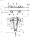
- FIG. 2 is a diagram showing the YF 2A attached to the rail 1R, as viewed from the front side with respect to the paper plane in FIG. 1
- FIG. 3 is a diagram showing the YF 2A as viewed from the back side with respect to the paper plane in FIG. 1
- FIGS. 2 and 3 show only one ridge 1b that is provided on a side surface of the rail 1R, and the YF 2A slides along this ridge 1b.
- the side shown in FIG. 2 will be called the front side of the YF 2A
- the side shown in FIG. 3 will be called the back side of the YF 2A.
- FIGS. 2 and 3 includes a main body portion 2M, a lower mounting portion 2L, and an upper mounting portion 2U.
- the configuration of the YF 2A shown in FIGS. 2 and 3 is merely one example, and there is no limitation to this configuration.
- the knitting yarn 9 is emphasized in FIGS. 2 and 3 in order to aid understanding of the path of the knitting yarn 9.
- the main body portion 2M is an elongated member that extends downward from the rail 1R, and includes traveling rollers 2r that sandwich the ridge 1b of the rail 1R from above and below. More specifically, the main body portion 2M is divided into a carrier portion 2a on which the traveling rollers 2r are provided, and a suspended portion 2b that extends so as to hang downward from the carrier portion 2a. In order to ensure strength, the main body portion 2M is preferably made of a metal. A pin groove 2h for receiving the changeover pin of the selector 1S shown in FIG. 1 is provided in the upper edge of the carrier portion 2a.
- a yarn feeding opening 2f for guiding the knitting yarn 9 to the needle bed gap is provided at the lower end of the suspended portion 2b
- a roller-shaped introduction guide 21 for guiding the knitting yarn 9 toward the yarn feeding opening 2f is provided somewhat upward of the intermediate portion.
- the introduction guide 21 of this embodiment is configured by a roller that has a rotation shaft that extends in the thickness direction of the main body portion 2M.
- the introduction guide 21 is provided on a small piece that extends in the extending direction of the rail 1R and is fixed to the suspended portion 2b, and more specifically in a portion of the small piece that projects out from the suspended portion 2b.
- the introduction guide 21 is not limited to being a roller, and may be a tubular member through which the knitting yarn 9 can pass, for example.
- the lower mounting portion 2L is attached at a position that is below the introduction guide 21.
- the lower mounting portion 2L appears to be a plate-shaped member in the drawings, it is actually constituted by combining a plate piece and a framework member or the like.
- This lower mounting portion 2L is for the mounting of electrical devices such as a tension sensor 4 and a tension adjusting apparatus 5 that are shown in FIG. 3 , and is made of an insulating material.
- a portion of the lower mounting portion 2L projects laterally from the main body portion 2M in a front view of the YF 2A from a direction orthogonal to the extending direction of the rail 1R, and as shown in FIG. 3 , the tension sensor 4 and the tension adjusting apparatus 5 are provided on the back side of this projecting portion.
- the upper mounting portion 2U is a plate-shaped member that is provided on the front side (side shown in FIG. 2 ) of the carrier portion 2a.
- the upper mounting portion 2U is for the mounting of a later-described control circuit 20 and the like, and is made of an insulating material.
- the front side of the carrier portion 2a may be formed with a box-like shape, and the upper mounting portion 2U may be stored inside the carrier portion 2a. In this case, if the carrier portion 2a is provided with a lid, it is possible to protect the control circuit 20 from dust and oil.
- a power supply portion 3 shown in FIG. 2 is configured to supply electrical power to an electrical device that is provided on the YF 2A, and in this embodiment, the power supply portion 3 is provided on the upper mounting portion 2U.
- the power supply portion 3 may be an active power supply that supplies electrical power from its own power supply, such as a battery, or may be a passive power supply that receives electrical power from outside of the YF 2A and supplies that electrical power to the electrical device. Examples of methods for supplying electrical power to the passive power supply include a contact type of power supply such as that described in Patent Document 1 or 2, and a contactless power supply method that utilizes electromagnetic induction or the like.
- the control circuit 20 is provided on the front side of the upper mounting portion 2U, and is electrically connected to the power supply portion 3.
- an optical wireless transceiver 6 is provided on the YF 2A, and the control circuit 20 of this embodiment has a communication control portion for the optical wireless transceiver 6.
- the YF 2A of this embodiment may include a tension control portion for controlling the tension adjusting apparatus 5 based on information from the tension sensor 4 as will be described later, and in this case, the tension control portion can be provided in the control circuit 20.
- These control portions provided on the YF 2A are controlled in coordination with each other by an overall control portion provided in the computer 10 of the flat knitting machine 1.
- optical wireless communication method of this embodiment employs infrared light, but may employ visible light.
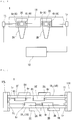
- the optical wireless system of this embodiment includes a main body side transmitter 1t and a main body side receiver 1r that are connected to the computer 10 of the flat knitting machine 1, and the optical wireless transceivers 6 that are provided on the YFs 2A and 2B.
- the optical wireless transceivers 6 each include an optical wireless YF side receiver 6r and YF side transmitter 6t, and a communication control portion that controls them.
- the members 6r and 6t of this embodiment are implemented in the control circuit 20, and an IC chip of the control circuit 20 is employed as the communication control portion.
- the main body side transmitter 1t is an apparatus that transmits knitting-related information from the computer 10 to the YFs 2A and 2B using optical wireless communication, and is arranged on a non-moving member on one end side of the rail 1R, such as a frame 1FL in FIG. 1 .
- the light projection axis of the main body side transmitter 1t is directly faced to the YF side receiver 6r of the YF 2A that is located closer to the main body side transmitter 1t.
- the main body side receiver 1r is an apparatus that receives information transmitted by the YF 2B using optical wireless communication, and is arranged on a non-moving member on the other end side of the rail 1R, such as a frame 1FR in FIG. 1 .
- the light reception axis of the main body side receiver 1r is directly faced to the YF side transmitter 6t of the YF 2B that is located closer to the main body side receiver 1r.
- the YF side receiver 6r of the YF 2A (2B) is provided at a position in the YF 2A (2B) that is on the one end side of the rail 1R, and the YF side transmitter 6t is provided at a position in the YF 2A (2B) that is on the other end side of the rail 1R.
- the light axis of the YF side transmitter 6t of the YF 2A is directly faced to the YF side receiver 6r of the YF 2B. According to this configuration, information transmitted from the one end side of the rail 1R can be easily received, and information can be easily transmitted to the other end side of the rail 1R.
- information transmitted through optical wireless communication from the main body side transmitter 1t to the main body side receiver 1r is relayed through the optical wireless transceivers 6 provided on the YFs 2A and 2B as shown by the outlined arrows.
- Information (first information) including individual instructions for the respective YFs 2 is transmitted from the main body side transmitter 1t. This information is first received by the control circuit 20 of the YF 2A, which extracts the instruction that is for itself, and then executes that instruction.
- the control circuit 20 of the YF 2A then adds information acquired by itself (e.g., later-described information regarding the tension of the knitting yarn, and position information) to the information received from the main body side transmitter 1t, and transmits the resulting information (second information) to the subsequent YF 2B.
- the YF 2B also extracts the instruction that is for itself, executes the extracted instruction, and then transmits information (including information acquired by the YF 2B) to the main body side receiver 1r.
- the information acquired by the YFs 2A and 2B is fed back to the computer 10 via the main body side receiver 1r and used for optimization of knitting conditions for example.
- the transmission of information acquired by the YFs 2A and 2B is not essential.
- examples of the information fed back to the computer 10 include information indicating that an instruction was received or indicating the result of executing an instruction.
- the YFs 2A and 2B may transmit the first information as it is without adding new information to the first information.
- FIG. 5 a first rail 1R 1 (1R) and a second rail 1R 2 (1R) adjacent thereto are seen from above.
- the rails 1R 1 and 1R 2 are each provided with two YFs among the YFs 2A to 2H on each of two tracks respectively on one surface side and the other surface side in the parallel arrangement direction.
- the communication direction with respect to the first feeder group made up of the YFs 2C and 2D and the communication direction with respect to the second feeder group made up of the YFs 2E and 2F are opposite directions.
- communication information from the main body side transmitter 1t on the first rail 1R 1 is not received by the YFs 2E and 2F on the second rail 1R 2
- communication signals from the YFs 2C and 2D are also not received by the YFs 2E and 2F.
- the YF side receivers 6r of the YFs 2C and 2D do not face the frame 1FL.
- the same can be said for communication information on the second rail 1R 2 as well, and by setting the communication directions opposite to each other for the adjacent feeder groups in this way, it is possible to suppress the erroneous transmission of information.
- the communication direction for the YFs 2A and 2B on the first rail 1R 1 and the communication direction for the YFs 2G and 2H on the second rail 1R 2 are set opposite to each other.
- the communication direction for the YFs 2A and 2B on the first rail 1R 1 and the communication direction for the YFs 2C and 2D are set opposite to each other. Also, erroneous transmission may be suppressed by shifting the timing of communication for each track.
- Examples of information exchanged in the optical wireless system include numbering information (e.g., ID numbers) of the YFs 2.
- numbering information e.g., ID numbers
- the computer 10 transmits, from the main body side transmitter 1t of the first rail 1R 1 , numbering information including an instruction for recognizing one's number in the order of signal reception.
- the YF 2C receives the numbering information first, recognizes itself as the first YF, and transmits numbering information including information related to itself to the YF 2D.
- the YF 2D recognizes itself as the second YF based on the received numbering information, and then transmits numbering information to the main body side receiver 1r.
- the computer 10 recognizes that the numbering of the first YF and the second YF has ended, and transmits numbering information from the main body side transmitter 1t of the second rail 1R 2 .
- the computer 10 recognizes that the YF 2E is the third YF, and that the YF 2F is the fourth YF.
- all of the YFs provided in the flat knitting machine 1 are numbered in order in the above configuration, one optical wireless system exists for each of the rails 1R 1 and 1R 2 in this embodiment, and therefore the YFs may be recognized separately for each rail.
- the YFs 2 can be numbered by merely transmitting numbering information.
- information is transmitted to all of the YFs 2 at the same time, and therefore the YFs 2 need to be numbered before being attached to the rails 1R 1 and 1R 2 .
- any of the YFs 2A to 2H are attached at the wrong position, there is a possibility that knitting cannot be performed. For this reason, the operation of attaching the YFs 2 requires a corresponding amount of precaution, and there is a risk of a decrease in the productivity of the flat knitting machine 1.
- One example of information transmitted from the YF 2A to the computer 10 in the optical wireless system is knitting-related information acquired by an electrical device provided on the YF 2A.
- the position measuring apparatus 7 shown in FIG. 3 is one example of the electrical device.
- the position measuring apparatus 7 measures the position of the YF 2A on the rail 1R.
- Examples of the position measuring apparatus 7 include an optical device that optically reads a scale provided on the rail 1R, and a Hall element that detects a linear scale provided along the rail 1R.
- the position of the YF 2A is transmitted to the computer 10 of the flat knitting machine 1 via the optical wireless transceiver 6.
- the computer 10 realizes optimal movement of the YF 2A based on the position information from the YF 2A.
- the stopping position of the YF 2A can be highly accurately controlled based on the position information.
- the position information from the YF 2A can be used to perform control for operating some sort of electrical device when the YF 2A reaches a predetermined position.
- the YF 2A of this embodiment includes the power supply portion 3, and thus can also be provided with an electrical device other than the position measuring apparatus 7.
- the YF 2A can be provided with the tension sensor 4 and the tension adjusting apparatus 5.
- the tension sensor 4 acquires a physical amount that is correlated with the tension of the knitting yarn 9, and outputs the physical amount to the control circuit 20 as an electrical signal. There are no particular limitations on the acquired physical amount, as long as it changes in correlation with change in the tension of the knitting yarn 9.
- the tension sensor 4 of this embodiment is configured by guide rollers 41 and 42 and a guide shaft portion 40 that is arranged at a position between the guide rollers 41 and 42.
- the guide shaft portion 40 is a roller-like member that comes into contact with the knitting yarn 9 and acquires a physical amount that corresponds to stress applied by the knitting yarn 9.
- the physical amount acquired by the tension sensor 4 is input to the control circuit 20 as an electrical signal.
- the control circuit 20 includes a tension control portion that estimates the tension of the knitting yarn 9 based on the physical amount, and controls the tension adjusting apparatus 5 such that the tension of the knitting yarn 9 approaches a set tension.
- the set tension may be transmitted to the YFs 2 using the optical wireless system.
- the tension adjusting apparatus 5 of this embodiment adjusts the tension of the knitting yarn 9 by acting on a portion of the knitting yarn 9 that spans between the introduction guide 21 and the tension sensor 4.
- information acquired by the tension sensor 4 may be transmitted by the optical wireless transceiver 6 as information regarding the tension of the knitting yarn 9.
Landscapes
- Engineering & Computer Science (AREA)
- Textile Engineering (AREA)
- Physics & Mathematics (AREA)
- Electromagnetism (AREA)
- Computer Networks & Wireless Communication (AREA)
- Signal Processing (AREA)
- Knitting Machines (AREA)
- Treatment Of Fiber Materials (AREA)
Abstract
Description
- The present invention relates to a flat knitting machine.
- A flat knitting machine includes a needle bed in which multiple knitting needles are arranged side-by-side, and is provided with multiple moving bodies that are involved in the knitting of a knitted fabric, and these moving bodies are attached to a rail and travel along the rail. One example of such moving bodies is yarn feeders (hereinafter, sometimes called "YF") that feed yarn to the knitting needles in the needle bed.
-
Patent Document 1 discloses a configuration in which a YF is driven by a linear motor, or a drive motor or the like is attached to a YF, such that the YF is self-propelled. The drive motor provided for the YF and the control apparatus for control thereof are supplied with electrical power through contact power supply that is performed via a contact strip provided on the rail. -
Patent Document 2 discloses a moving body (reference sign 300 in Patent Document 2) that travels on a rail to which the YF is attached, and that moves the YF by inserting a changeover pin into the YF. InPatent Document 2, the insertion and removal of the changeover pin is performed using electrical power that is supplied to the moving body through contact between a conductive sheet provided on the rail and a carbon brush provided on the moving body. -
- Patent Document 1: German Patent Application Publication No.
4308251 - Patent Document 2: Chinese Patent Application Publication No.
101139777 - As disclosed in
Patent Document 1, there has been a proposal to provide a YF with a device that operates electrically. In this case, information indicating a device operation timing and the like needs to be transmitted to the YF. Wireless transmission can be performed using Wi-Fi (registered trademark) or the like, but it is troublesome to create specifications that comply with radio laws in various countries. On the other hand, it is possible to perform optical wireless communication, which can be used regardless of radio laws, but unlike radio waves, information cannot be transmitted around obstacles, and therefore it is difficult to transmit information to each of the plurality of YFs provided in a flat knitting machine. YFs frequently change position when knitting a knitted fabric, and therefore if a YF or the like becomes located between an optical wireless transmitter and a target YF, information cannot be transmitted to the target YF. - The present invention was achieved in light of the foregoing circumstances, and an object thereof is to provide a flat knitting machine in which information can be reliably transmitted to a target yarn feeder using optical wireless communication.
- A flat knitting machine of the present invention includes a needle bed having a plurality of knitting needles, a rail extending along a length direction of the needle bed, a plurality of yarn feeders provided on the rail, and a computer that controls the flat knitting machine, the flat knitting machine including:
- a main body side transmitter that is provided in a vicinity of one end of the rail and transmits knitting-related information from the computer in a direction along the rail through optical wireless transmission;
- a main body side receiver that is provided in a vicinity of an other end of the rail, receives the information transmitted through optical wireless transmission, and sends the information to the computer; and
- an optical wireless transceiver that is provided in each of the yarn feeders, receives the information transmitted from the main body side transmitter, and relays the information to the main body side receiver.
- In an aspect of the flat knitting machine of the present invention, the optical wireless transceivers each include
a YF side receiver that is provided on the yarn feeder at a position on one end side of the rail and has a light reception axis that is directed toward the one end side, and
a YF side transmitter that is provided on the yarn feeder at a position on an other end side of the rail and has a light projection axis that is directed toward the other end side. - In an aspect of the flat knitting machine of the present invention, the flat knitting machine further includes: a first feeder group made up of a plurality of the yarn feeders that travel on a same track; and
a second feeder group made up of a plurality of the yarn feeders that travel on another track that is adjacent to the track on which the first feeder group travels,
wherein a communication direction with respect to the first feeder group and a communication direction with respect to the second feeder group are opposite directions. - In an aspect of the flat knitting machine of the present invention, the yarn feeders each include at least one electrical device that acquires knitting-related information in addition to the optical wireless transceiver, and
the information acquired by the at least one electrical device is transmitted to the computer through optical wireless communication. - According to the above configuration of the flat knitting machine of the present invention, knitting-related first information is transmitted from the main body side transmitter. Each YF relays, to the main body side receiver, knitting-related second information which includes further information successively added by each of the YFs to the first information. Alternatively, each YF may relay, to the main body side receiver, the first information as it is. Therefore, even if a plurality of YFs are provided on one track, information can be reliably transmitted to each of the YFs by performing optical wireless communication in which the information is successively relayed by the optical wireless transceivers provided on the YFs. Here, the track is a YF traveling route formed on the rail. If a plurality of YFs are provided on the same track, the YFs on that track travel back and forth on the same straight line. The YF located on one end side of the track cannot pass a YF on the other end side of that YF in order to travel toward the other end side.
- The YF side receiver is provided at a position on the one end side of the rail, and the YF side transmitter is provided at a position on the other end side of the rail, and therefore the YFs can easily receive information from the one end side and easily transmit information to the other end side, thus making it possible for information to be easily transmitted from the one end side of the rail to the other end side. Also, the YFs arranged on the same track can have the same configuration. Here, if, in contrast to the above configuration, the YF side receiver is arranged on the other end side of each YF, and the YF side transmitter is arranged on the one end side of each YF, YFs that are adjacent on the track need to have different configurations. In the case of optical wireless communication in which transmission is performed from the one end side to the other end side, if the YF side receiver on the other end side and the YF side transmitter on the one end side are arranged at the same height position in each YF, there is a problem that the YF side transmitter acts as a wall and makes reception by the YF side receiver difficult, and there is a problem that a signal from the YF side transmitter is received by the YF side receiver of the same YF. For this reason, the YF side receiver and the YF side transmitter in each YF need to be arranged at different heights. In this case, the vertical positional relationship between the YF side transmitter and the YF side receiver of one of two adjacent YFs needs to be made opposite to that of the YF side transmitter and the YF side receiver of the other YF.
- One feeder group and another feeder group that are adjacent in the rail parallel arrangement direction are given opposite communication directions in optical wireless communication, thus making it possible to suppress the case where information is transmitted to the wrong YF.
- Information acquired by the electrical devices provided on the YFs is fed back to the computer, thus making it possible to improve knitting conditions and improve knitting efficiency.
-
-
FIG. 1 is a schematic front view of a flat knitting machine according to an embodiment. -
FIG. 2 is a schematic diagram of a yarn feeder viewed from one side of a rail. -
FIG. 3 is a schematic diagram of the yarn feeder viewed from the side opposite to that inFIG. 2 . -
FIG. 4 is a schematic illustrative diagram of an optical wireless system that relays information to an optical wireless transceiver provided on the yarn feeder. -
FIG. 5 is an illustrative diagram that illustrates an example of communication directions on parallel rails. - A
flat knitting machine 1 according to an embodiment of the present invention will be described below with reference toFIGS. 1 to 5 . - As shown in
FIG. 1 , theflat knitting machine 1 includes a pair ofneedle beds 1B that are arranged facing each other in the depth direction with respect to the paper plane, and yarn feeders (hereinafter, called "YF") 2A to 2D that feedknitting yarn 9 to a needle bed gap formed between the twoneedle beds 1B. Multiple knitting needles are aligned in eachneedle bed 1B, and these knitting needles are driven by a cam system (not shown) provided in acarriage 1C that moves back and forth over theneedle bed 1B. Also, theYFs 2A to 2D travel along arail 1R. Therail 1R spans between a pair of frames 1FR and 1FL, which are immovable members that are provided upright on respective end sides of theflat knitting machine 1 and are integrated with theflat knitting machine 1.Multiple rails 1R are provided parallel with each other in the depth direction with respect to the paper plane, and therails 1R each extend parallel with theneedle beds 1B at positions above theneedle beds 1B. Hereinafter, when giving descriptions that are common to all of theYFs 2A to 2D, the term "YFs 2" will be used instead of distinguishing between theYFs 2A to 2D. - In this embodiment,
multiple YFs 2 are attached to eachrail 1R. TheYFs rail 1R that is on the front side with respect to the paper plane, and theYFs rail 1R that is on the back side with respect to the paper plane. These YFs 2 travel along therail 1R by being selected and moved by aselector 1S that hangs over therail 1R. TheYFs 2 are selected by engagement with a retractable changeover pin that is provided in theselector 1S. Theselector 1S is coupled to thecarriage 1C, and moves integrally with thecarriage 1C. When theselector 1S selects and moves theYFs 2 to be used in knitting, knitting is performed using theknitting yarn 9 that is supplied from theYFs 2. Note that the configuration for moving theYFs 2 is not limited to the configuration in this embodiment, and can be a configuration in which theYFs 2 are self-propelled. The operations of thecarriage 1C and theselector 1S are controlled by acomputer 10 that is provided in theflat knitting machine 1. - The
YFs 2 are each supplied withknitting yarn 9 from a knitting yarn supply source (not shown) such as a cone that is arranged above theflat knitting machine 1 for example, and theknitting yarn 9 is fed via atension equipment 90 and furthermore via a side tension device (not shown) provided on a lateral side of theflat knitting machine 1. In other words, theYFs 2 in this embodiment are configured to receive a supply of theknitting yarn 9 from its lateral side. In contrast to this example, a configuration is possible in which theYFs 2 receive a supply of theknitting yarn 9 from above. - The
flat knitting machine 1 of this embodiment is provided with an optical wireless system that enables the exchange of information between thecomputer 10 and theYFs 2. In order to exchange information, theYFs 2 need to be provided with an optical wireless transceiver and a power supply portion for supplying electrical power. First, the schematic configuration of theYFs 2 of this embodiment will be described with reference toFIGS. 2 and3 , then a control circuit and the power supply portion will be described briefly, and lastly, the optical wireless system and the information exchanged in this system will be described. -
FIG. 2 is a diagram showing theYF 2A attached to therail 1R, as viewed from the front side with respect to the paper plane inFIG. 1 , andFIG. 3 is a diagram showing theYF 2A as viewed from the back side with respect to the paper plane inFIG. 1 .FIGS. 2 and3 show only oneridge 1b that is provided on a side surface of therail 1R, and theYF 2A slides along thisridge 1b. For the sake of convenience, the side shown inFIG. 2 will be called the front side of theYF 2A, and the side shown inFIG. 3 will be called the back side of theYF 2A. TheYF 2A of this embodiment shown inFIGS. 2 and3 includes amain body portion 2M, alower mounting portion 2L, and an upper mountingportion 2U. Of course, the configuration of theYF 2A shown inFIGS. 2 and3 is merely one example, and there is no limitation to this configuration. Note that theknitting yarn 9 is emphasized inFIGS. 2 and3 in order to aid understanding of the path of theknitting yarn 9. - As shown in
FIG. 3 , themain body portion 2M is an elongated member that extends downward from therail 1R, and includes travelingrollers 2r that sandwich theridge 1b of therail 1R from above and below. More specifically, themain body portion 2M is divided into acarrier portion 2a on which the travelingrollers 2r are provided, and a suspendedportion 2b that extends so as to hang downward from thecarrier portion 2a. In order to ensure strength, themain body portion 2M is preferably made of a metal. Apin groove 2h for receiving the changeover pin of theselector 1S shown inFIG. 1 is provided in the upper edge of thecarrier portion 2a. Also, ayarn feeding opening 2f for guiding theknitting yarn 9 to the needle bed gap is provided at the lower end of the suspendedportion 2b, and a roller-shaped introduction guide 21 for guiding theknitting yarn 9 toward theyarn feeding opening 2f is provided somewhat upward of the intermediate portion. The introduction guide 21 of this embodiment is configured by a roller that has a rotation shaft that extends in the thickness direction of themain body portion 2M. Theintroduction guide 21 is provided on a small piece that extends in the extending direction of therail 1R and is fixed to the suspendedportion 2b, and more specifically in a portion of the small piece that projects out from the suspendedportion 2b. Note that theintroduction guide 21 is not limited to being a roller, and may be a tubular member through which theknitting yarn 9 can pass, for example. - The
lower mounting portion 2L is attached at a position that is below theintroduction guide 21. Although thelower mounting portion 2L appears to be a plate-shaped member in the drawings, it is actually constituted by combining a plate piece and a framework member or the like. This lower mountingportion 2L is for the mounting of electrical devices such as atension sensor 4 and atension adjusting apparatus 5 that are shown inFIG. 3 , and is made of an insulating material. A portion of thelower mounting portion 2L projects laterally from themain body portion 2M in a front view of theYF 2A from a direction orthogonal to the extending direction of therail 1R, and as shown inFIG. 3 , thetension sensor 4 and thetension adjusting apparatus 5 are provided on the back side of this projecting portion. - The upper mounting
portion 2U is a plate-shaped member that is provided on the front side (side shown inFIG. 2 ) of thecarrier portion 2a. The upper mountingportion 2U is for the mounting of a later-describedcontrol circuit 20 and the like, and is made of an insulating material. The front side of thecarrier portion 2a may be formed with a box-like shape, and the upper mountingportion 2U may be stored inside thecarrier portion 2a. In this case, if thecarrier portion 2a is provided with a lid, it is possible to protect thecontrol circuit 20 from dust and oil. - A power supply portion 3 shown in
FIG. 2 is configured to supply electrical power to an electrical device that is provided on theYF 2A, and in this embodiment, the power supply portion 3 is provided on the upper mountingportion 2U. The power supply portion 3 may be an active power supply that supplies electrical power from its own power supply, such as a battery, or may be a passive power supply that receives electrical power from outside of theYF 2A and supplies that electrical power to the electrical device. Examples of methods for supplying electrical power to the passive power supply include a contact type of power supply such as that described inPatent Document - The
control circuit 20 is provided on the front side of the upper mountingportion 2U, and is electrically connected to the power supply portion 3. In this embodiment, anoptical wireless transceiver 6 is provided on theYF 2A, and thecontrol circuit 20 of this embodiment has a communication control portion for theoptical wireless transceiver 6. Also, theYF 2A of this embodiment may include a tension control portion for controlling thetension adjusting apparatus 5 based on information from thetension sensor 4 as will be described later, and in this case, the tension control portion can be provided in thecontrol circuit 20. These control portions provided on theYF 2A are controlled in coordination with each other by an overall control portion provided in thecomputer 10 of theflat knitting machine 1. - The following describes an example of an optical wireless system in which information is exchanged between the
computer 10 and theYFs flat knitting machine 1, with reference toFIG. 4 . The optical wireless communication method of this embodiment employs infrared light, but may employ visible light. - In the example shown in
FIG. 4 , the twoYFs rail 1R. The optical wireless system of this embodiment includes a mainbody side transmitter 1t and a mainbody side receiver 1r that are connected to thecomputer 10 of theflat knitting machine 1, and theoptical wireless transceivers 6 that are provided on theYFs optical wireless transceivers 6 each include an optical wirelessYF side receiver 6r andYF side transmitter 6t, and a communication control portion that controls them. Themembers control circuit 20, and an IC chip of thecontrol circuit 20 is employed as the communication control portion. - The main
body side transmitter 1t is an apparatus that transmits knitting-related information from thecomputer 10 to theYFs rail 1R, such as a frame 1FL inFIG. 1 . The light projection axis of the mainbody side transmitter 1t is directly faced to theYF side receiver 6r of theYF 2A that is located closer to the mainbody side transmitter 1t. Also, the mainbody side receiver 1r is an apparatus that receives information transmitted by theYF 2B using optical wireless communication, and is arranged on a non-moving member on the other end side of therail 1R, such as a frame 1FR inFIG. 1 . The light reception axis of the mainbody side receiver 1r is directly faced to theYF side transmitter 6t of theYF 2B that is located closer to the mainbody side receiver 1r. - The
YF side receiver 6r of theYF 2A (2B) is provided at a position in theYF 2A (2B) that is on the one end side of therail 1R, and theYF side transmitter 6t is provided at a position in theYF 2A (2B) that is on the other end side of therail 1R. The light axis of theYF side transmitter 6t of theYF 2A is directly faced to theYF side receiver 6r of theYF 2B. According to this configuration, information transmitted from the one end side of therail 1R can be easily received, and information can be easily transmitted to the other end side of therail 1R. - According to the optical wireless system having the above-described configuration, information transmitted through optical wireless communication from the main
body side transmitter 1t to the mainbody side receiver 1r is relayed through theoptical wireless transceivers 6 provided on theYFs respective YFs 2 is transmitted from the mainbody side transmitter 1t. This information is first received by thecontrol circuit 20 of theYF 2A, which extracts the instruction that is for itself, and then executes that instruction. Thecontrol circuit 20 of theYF 2A then adds information acquired by itself (e.g., later-described information regarding the tension of the knitting yarn, and position information) to the information received from the mainbody side transmitter 1t, and transmits the resulting information (second information) to thesubsequent YF 2B. Similarly to theYF 2A, theYF 2B also extracts the instruction that is for itself, executes the extracted instruction, and then transmits information (including information acquired by theYF 2B) to the mainbody side receiver 1r. The information acquired by theYFs computer 10 via the mainbody side receiver 1r and used for optimization of knitting conditions for example. The above-described usage of information and transmission procedure are the same even when there are three or more YFs. Here, the transmission of information acquired by theYFs computer 10 include information indicating that an instruction was received or indicating the result of executing an instruction. In addition, while theYFs - Next, a preferable example of communication directions in the case where the
rails 1R are parallel will be described with reference toFIG. 5 . InFIG. 5 , afirst rail 1R1 (1R) and asecond rail 1R2 (1R) adjacent thereto are seen from above. Therails YFs 2A to 2H on each of two tracks respectively on one surface side and the other surface side in the parallel arrangement direction. - As shown in
FIG. 5 , on thefirst rail 1R1, communication with respect to theYFs second rail 1R2 is performed in the rightward direction with respect to the paper plane. In this case, letting the side on which the frame 1FL is arranged be the one end side of thefirst rail 1R1, and letting the side on which the frame 1FR is arranged be the other end side of thefirst rail 1R1, the mainbody side transmitter 1t is provided on the frame 1FL, and the mainbody side receiver 1r is provided on the frame 1FR. On thesecond rail 1R2, communication with respect to theYFs first rail 1R1 is performed in the leftward direction with respect to the paper plane, which is opposite to the communication direction with respect to theYFs second rail 1R2, and letting the side on which the frame 1FL is arranged be the other end side of thesecond rail 1R2, the mainbody side transmitter 1t is provided on the frame 1FR, and the mainbody side receiver 1r is provided on the frame 1FL. - In this embodiment, the communication direction with respect to the first feeder group made up of the
YFs YFs body side transmitter 1t on thefirst rail 1R1 is not received by theYFs second rail 1R2, and communication signals from theYFs YFs YF side receivers 6r of theYFs second rail 1R2 as well, and by setting the communication directions opposite to each other for the adjacent feeder groups in this way, it is possible to suppress the erroneous transmission of information. - Here, there are no particular limitations on the communication direction for the
YFs first rail 1R1 and the communication direction for theYFs second rail 1R2. This is because in this embodiment, in the case of the feeder group made up of theYFs first rail 1R1 (second rail 1R2) functions as a wall such that communication signals do not reach the other feed group. Here, in the case where therail 1R is narrow and does not function as a wall, it is preferable that the communication direction for the feeder group on one track of onerail 1R and the communication direction for the feeder group on the other track of the same rail are set opposite to each other. For example, the communication direction for theYFs first rail 1R1 and the communication direction for theYFs - Examples of information exchanged in the optical wireless system include numbering information (e.g., ID numbers) of the
YFs 2. For example, consider the case where theYFs FIG. 5 are respectively registered as the first, second, third, and fourth YFs in thecomputer 10. First, thecomputer 10 transmits, from the mainbody side transmitter 1t of thefirst rail 1R1, numbering information including an instruction for recognizing one's number in the order of signal reception. TheYF 2C receives the numbering information first, recognizes itself as the first YF, and transmits numbering information including information related to itself to theYF 2D. TheYF 2D recognizes itself as the second YF based on the received numbering information, and then transmits numbering information to the mainbody side receiver 1r. Thecomputer 10 recognizes that the numbering of the first YF and the second YF has ended, and transmits numbering information from the mainbody side transmitter 1t of thesecond rail 1R2. As a result, thecomputer 10 recognizes that theYF 2E is the third YF, and that theYF 2F is the fourth YF. Although all of the YFs provided in theflat knitting machine 1 are numbered in order in the above configuration, one optical wireless system exists for each of therails - As described above, in the optical wireless system of this embodiment, information is transmitted to the
YFs 2 in a determined order, and therefore theYFs 2 can be numbered by merely transmitting numbering information. In contrast, in the case of wireless communication performed using radio waves, information is transmitted to all of theYFs 2 at the same time, and therefore theYFs 2 need to be numbered before being attached to therails YFs 2A to 2H are attached at the wrong position, there is a possibility that knitting cannot be performed. For this reason, the operation of attaching theYFs 2 requires a corresponding amount of precaution, and there is a risk of a decrease in the productivity of theflat knitting machine 1. - One example of information transmitted from the
YF 2A to thecomputer 10 in the optical wireless system is knitting-related information acquired by an electrical device provided on theYF 2A. For example, theposition measuring apparatus 7 shown inFIG. 3 is one example of the electrical device. Theposition measuring apparatus 7 measures the position of theYF 2A on therail 1R. Examples of theposition measuring apparatus 7 include an optical device that optically reads a scale provided on therail 1R, and a Hall element that detects a linear scale provided along therail 1R. The position of theYF 2A is transmitted to thecomputer 10 of theflat knitting machine 1 via theoptical wireless transceiver 6. Thecomputer 10 realizes optimal movement of theYF 2A based on the position information from theYF 2A. For example, if theYF 2A is provided with a brake mechanism, the stopping position of theYF 2A can be highly accurately controlled based on the position information. Also, the position information from theYF 2A can be used to perform control for operating some sort of electrical device when theYF 2A reaches a predetermined position. - The
YF 2A of this embodiment includes the power supply portion 3, and thus can also be provided with an electrical device other than theposition measuring apparatus 7. For example, as shown inFIG. 3 , theYF 2A can be provided with thetension sensor 4 and thetension adjusting apparatus 5. - The
tension sensor 4 acquires a physical amount that is correlated with the tension of theknitting yarn 9, and outputs the physical amount to thecontrol circuit 20 as an electrical signal. There are no particular limitations on the acquired physical amount, as long as it changes in correlation with change in the tension of theknitting yarn 9. Thetension sensor 4 of this embodiment is configured byguide rollers guide shaft portion 40 that is arranged at a position between theguide rollers guide shaft portion 40 is a roller-like member that comes into contact with theknitting yarn 9 and acquires a physical amount that corresponds to stress applied by theknitting yarn 9. - The physical amount acquired by the
tension sensor 4 is input to thecontrol circuit 20 as an electrical signal. Thecontrol circuit 20 includes a tension control portion that estimates the tension of theknitting yarn 9 based on the physical amount, and controls thetension adjusting apparatus 5 such that the tension of theknitting yarn 9 approaches a set tension. The set tension may be transmitted to theYFs 2 using the optical wireless system. Thetension adjusting apparatus 5 of this embodiment adjusts the tension of theknitting yarn 9 by acting on a portion of theknitting yarn 9 that spans between theintroduction guide 21 and thetension sensor 4. In the case where thetension adjusting apparatus 5 is provided external to theYFs 2, information acquired by thetension sensor 4 may be transmitted by theoptical wireless transceiver 6 as information regarding the tension of theknitting yarn 9.
Claims (4)
- A flat knitting machine (1) including a needle bed (1B) having a plurality of knitting needles, a rail (1R) extending along a length direction of the needle bed (1B), a plurality of yarn feeders (2) provided on the rail (1R), and a computer (10) that controls the flat knitting machine (1), the flat knitting machine (1) characterized by:a main body side transmitter (1t) that is provided in a vicinity of one end of the rail (1R) and transmits knitting-related information from the computer (10) in a direction along the rail (1R) through optical wireless transmission;a main body side receiver (1r) that is provided in a vicinity of an other end of the rail (1R), receives the information transmitted through optical wireless transmission, and sends the information to the computer (10); andan optical wireless transceiver (6) that is provided on each of the yarn feeders (2), receives the information transmitted from the main body side transmitter (1t), and relays the information to the main body side receiver (1r).
- The flat knitting machine (1) according to claim 1,
wherein the optical wireless transceivers 6 each includea YF side receiver (6r) that is provided on the yarn feeder (2A) at a position on one end side of the rail (1R) and has a light reception axis that is directed toward the one end side, anda YF side transmitter (6t) that is provided on the yarn feeder (2A) at a position on an other end side of the rail (1R) and has a light projection axis that is directed toward the other end side. - The flat knitting machine (1) according to claim 1 or 2, further comprising:a first feeder group made up of a plurality of the yarn feeders (2C, 2D) that travel on a same track; anda second feeder group made up of a plurality of the yarn feeders (2E, 2F) that travel on another track that is adjacent to the track on which the first feeder group travels,wherein a communication direction with respect to the first feeder group and a communication direction with respect to the second feeder group are opposite directions.
- The flat knitting machine (1) according to any one of claims 1 to 3,
wherein the yarn feeders (2) each include at least one electrical device (4, 7) that acquires knitting-related information in addition to the optical wireless transceiver (6), and
the information acquired by the at least one electrical device (4, 7) is transmitted to the computer (10) through optical wireless communication.
Applications Claiming Priority (1)
| Application Number | Priority Date | Filing Date | Title |
|---|---|---|---|
| JP2018069639 | 2018-03-30 |
Publications (2)
| Publication Number | Publication Date |
|---|---|
| EP3546631A1 true EP3546631A1 (en) | 2019-10-02 |
| EP3546631B1 EP3546631B1 (en) | 2021-06-23 |
Family
ID=66001100
Family Applications (1)
| Application Number | Title | Priority Date | Filing Date |
|---|---|---|---|
| EP19166016.6A Active EP3546631B1 (en) | 2018-03-30 | 2019-03-28 | Flat knitting machine |
Country Status (4)
| Country | Link |
|---|---|
| EP (1) | EP3546631B1 (en) |
| JP (1) | JP7307573B2 (en) |
| KR (1) | KR102191456B1 (en) |
| CN (1) | CN110318149B (en) |
Cited By (1)
| Publication number | Priority date | Publication date | Assignee | Title |
|---|---|---|---|---|
| US11987913B2 (en) * | 2021-07-13 | 2024-05-21 | Jiangnan University | Yarn carrier device with yarn tension control function for flat knitting machine, and yarn tension control method |
Citations (2)
| Publication number | Priority date | Publication date | Assignee | Title |
|---|---|---|---|---|
| DE4308251A1 (en) | 1992-03-17 | 1993-11-04 | Schieber Universal Maschf | Textile machine for flat-bed knitters |
| CN101139777A (en) | 2007-09-29 | 2008-03-12 | 冯加林 | Power control signal leading-in device for computer straight-bar machine shuttle box controlling mechanism |
Family Cites Families (14)
| Publication number | Priority date | Publication date | Assignee | Title |
|---|---|---|---|---|
| DE2658588C3 (en) * | 1976-12-23 | 1980-09-18 | Universal-Maschinenfabrik Dr. Rudolf Schieber Gmbh & Co Kg, 7081 Westhausen | Device for wireless data transmission on flat knitting machines |
| US4308251A (en) | 1980-01-11 | 1981-12-29 | Boots Pharmaceuticals, Inc. | Controlled release formulations of orally-active medicaments |
| US4819285A (en) * | 1986-07-11 | 1989-04-11 | Indwell Products Corporation | Portable collapsible baby crib |
| KR940006074B1 (en) * | 1991-11-18 | 1994-07-06 | 박윤식 | Locking device for a starting key of a car |
| JP3699554B2 (en) * | 1997-02-10 | 2005-09-28 | 大竹 和衛 | Automatic flat knitting machine |
| JP3044370B2 (en) * | 1997-08-21 | 2000-05-22 | 株式会社島精機製作所 | Yarn supply device in flat knitting machine |
| DE10234545B4 (en) * | 2002-07-30 | 2005-12-15 | Memminger-Iro Gmbh | Method and device for delivering threads |
| JP4125212B2 (en) * | 2003-10-10 | 2008-07-30 | 株式会社島精機製作所 | Flat knitting machine provided with removable knitting moving body and knitting member switching device |
| KR101139777B1 (en) | 2010-05-12 | 2012-04-26 | 국방과학연구소 | Reactive material composition for a less sensitive explosive reactive armor and a pressing thereof |
| CN102071530A (en) * | 2010-07-16 | 2011-05-25 | 宁波普罗蒂电脑横机有限公司 | Infrared numerical control photoelectric yarn feeding device of computerized flat knitting machine |
| CN202175828U (en) * | 2011-07-22 | 2012-03-28 | 向子云 | Computer flat knitting machine probe system |
| CN104731008B (en) * | 2015-03-17 | 2017-12-08 | 三明学院 | A kind of embedded electronic jacquard comb |
| CN106506713B (en) * | 2016-10-09 | 2019-04-12 | 三明学院 | Mix isomery serial communication system and dynamic device allocation address approach |
| CN206706323U (en) * | 2017-05-19 | 2017-12-05 | 宁波必沃纺织机械有限公司 | A kind of intelligent float detector of Computerized flat knitting machine |
-
2019
- 2019-03-26 JP JP2019058825A patent/JP7307573B2/en active Active
- 2019-03-28 EP EP19166016.6A patent/EP3546631B1/en active Active
- 2019-03-29 CN CN201910249295.9A patent/CN110318149B/en active Active
- 2019-03-29 KR KR1020190036527A patent/KR102191456B1/en active Active
Patent Citations (2)
| Publication number | Priority date | Publication date | Assignee | Title |
|---|---|---|---|---|
| DE4308251A1 (en) | 1992-03-17 | 1993-11-04 | Schieber Universal Maschf | Textile machine for flat-bed knitters |
| CN101139777A (en) | 2007-09-29 | 2008-03-12 | 冯加林 | Power control signal leading-in device for computer straight-bar machine shuttle box controlling mechanism |
Cited By (1)
| Publication number | Priority date | Publication date | Assignee | Title |
|---|---|---|---|---|
| US11987913B2 (en) * | 2021-07-13 | 2024-05-21 | Jiangnan University | Yarn carrier device with yarn tension control function for flat knitting machine, and yarn tension control method |
Also Published As
| Publication number | Publication date |
|---|---|
| JP7307573B2 (en) | 2023-07-12 |
| CN110318149B (en) | 2020-11-27 |
| KR102191456B1 (en) | 2020-12-15 |
| KR20190114878A (en) | 2019-10-10 |
| CN110318149A (en) | 2019-10-11 |
| EP3546631B1 (en) | 2021-06-23 |
| JP2019183369A (en) | 2019-10-24 |
Similar Documents
| Publication | Publication Date | Title |
|---|---|---|
| AU2009281029B2 (en) | Arrangement and method for determining the position of an elevator car | |
| US7599427B2 (en) | Micro range radio frequency (RF) communications link | |
| EP3450370B1 (en) | Elevator position detection systems | |
| EP2754582A1 (en) | Train control system | |
| EP3546631B1 (en) | Flat knitting machine | |
| US11212951B2 (en) | Component mounting system | |
| EP2292461A2 (en) | Moving vehicle system and method of controlling moving vehicles | |
| EP3546630A1 (en) | Flat knitting machine | |
| KR20190114875A (en) | Flat knitting machine | |
| US4658603A (en) | Device for setting the adjustable traverse of the yarn feeders of a flat knitting machine | |
| JP2024069334A5 (en) | ||
| US4167861A (en) | Flatbed knitting machine including control data conveying means | |
| CN106592026B (en) | With service unit weaving loom and before station positioning service unit method | |
| JP2008162548A (en) | Radio train control system | |
| JP2015099880A (en) | Work machine | |
| CN212270373U (en) | Yarn conveying device for detecting yarn scab | |
| JP2009123156A (en) | Transport vehicle system | |
| KR102015583B1 (en) | A working machine | |
| JP2017095201A (en) | Elevator | |
| EP2746882A1 (en) | Control device and control method for a conveying system of a machine | |
| CN207390351U (en) | A kind of position adjusting mechanism on automated production equipment | |
| CN106379739B (en) | A synchronous pick-and-place mechanism capable of adjusting the orientation of workpieces before installation | |
| CN202727610U (en) | Laser coding apparatus for cigarette sorting line | |
| CN205442106U (en) | Smart card guiding mechanism | |
| US9663300B2 (en) | System having a link chain |
Legal Events
| Date | Code | Title | Description |
|---|---|---|---|
| PUAI | Public reference made under article 153(3) epc to a published international application that has entered the european phase |
Free format text: ORIGINAL CODE: 0009012 |
|
| STAA | Information on the status of an ep patent application or granted ep patent |
Free format text: STATUS: THE APPLICATION HAS BEEN PUBLISHED |
|
| AK | Designated contracting states |
Kind code of ref document: A1 Designated state(s): AL AT BE BG CH CY CZ DE DK EE ES FI FR GB GR HR HU IE IS IT LI LT LU LV MC MK MT NL NO PL PT RO RS SE SI SK SM TR |
|
| AX | Request for extension of the european patent |
Extension state: BA ME |
|
| STAA | Information on the status of an ep patent application or granted ep patent |
Free format text: STATUS: REQUEST FOR EXAMINATION WAS MADE |
|
| 17P | Request for examination filed |
Effective date: 20200316 |
|
| RBV | Designated contracting states (corrected) |
Designated state(s): AL AT BE BG CH CY CZ DE DK EE ES FI FR GB GR HR HU IE IS IT LI LT LU LV MC MK MT NL NO PL PT RO RS SE SI SK SM TR |
|
| GRAP | Despatch of communication of intention to grant a patent |
Free format text: ORIGINAL CODE: EPIDOSNIGR1 |
|
| STAA | Information on the status of an ep patent application or granted ep patent |
Free format text: STATUS: GRANT OF PATENT IS INTENDED |
|
| INTG | Intention to grant announced |
Effective date: 20210126 |
|
| GRAS | Grant fee paid |
Free format text: ORIGINAL CODE: EPIDOSNIGR3 |
|
| GRAA | (expected) grant |
Free format text: ORIGINAL CODE: 0009210 |
|
| STAA | Information on the status of an ep patent application or granted ep patent |
Free format text: STATUS: THE PATENT HAS BEEN GRANTED |
|
| AK | Designated contracting states |
Kind code of ref document: B1 Designated state(s): AL AT BE BG CH CY CZ DE DK EE ES FI FR GB GR HR HU IE IS IT LI LT LU LV MC MK MT NL NO PL PT RO RS SE SI SK SM TR |
|
| REG | Reference to a national code |
Ref country code: GB Ref legal event code: FG4D |
|
| REG | Reference to a national code |
Ref country code: CH Ref legal event code: EP |
|
| REG | Reference to a national code |
Ref country code: DE Ref legal event code: R096 Ref document number: 602019005476 Country of ref document: DE Ref country code: AT Ref legal event code: REF Ref document number: 1404412 Country of ref document: AT Kind code of ref document: T Effective date: 20210715 |
|
| REG | Reference to a national code |
Ref country code: IE Ref legal event code: FG4D |
|
| REG | Reference to a national code |
Ref country code: LT Ref legal event code: MG9D |
|
| PG25 | Lapsed in a contracting state [announced via postgrant information from national office to epo] |
Ref country code: BG Free format text: LAPSE BECAUSE OF FAILURE TO SUBMIT A TRANSLATION OF THE DESCRIPTION OR TO PAY THE FEE WITHIN THE PRESCRIBED TIME-LIMIT Effective date: 20210923 Ref country code: LT Free format text: LAPSE BECAUSE OF FAILURE TO SUBMIT A TRANSLATION OF THE DESCRIPTION OR TO PAY THE FEE WITHIN THE PRESCRIBED TIME-LIMIT Effective date: 20210623 Ref country code: HR Free format text: LAPSE BECAUSE OF FAILURE TO SUBMIT A TRANSLATION OF THE DESCRIPTION OR TO PAY THE FEE WITHIN THE PRESCRIBED TIME-LIMIT Effective date: 20210623 Ref country code: FI Free format text: LAPSE BECAUSE OF FAILURE TO SUBMIT A TRANSLATION OF THE DESCRIPTION OR TO PAY THE FEE WITHIN THE PRESCRIBED TIME-LIMIT Effective date: 20210623 |
|
| REG | Reference to a national code |
Ref country code: AT Ref legal event code: MK05 Ref document number: 1404412 Country of ref document: AT Kind code of ref document: T Effective date: 20210623 |
|
| PG25 | Lapsed in a contracting state [announced via postgrant information from national office to epo] |
Ref country code: RS Free format text: LAPSE BECAUSE OF FAILURE TO SUBMIT A TRANSLATION OF THE DESCRIPTION OR TO PAY THE FEE WITHIN THE PRESCRIBED TIME-LIMIT Effective date: 20210623 Ref country code: SE Free format text: LAPSE BECAUSE OF FAILURE TO SUBMIT A TRANSLATION OF THE DESCRIPTION OR TO PAY THE FEE WITHIN THE PRESCRIBED TIME-LIMIT Effective date: 20210623 Ref country code: LV Free format text: LAPSE BECAUSE OF FAILURE TO SUBMIT A TRANSLATION OF THE DESCRIPTION OR TO PAY THE FEE WITHIN THE PRESCRIBED TIME-LIMIT Effective date: 20210623 Ref country code: NO Free format text: LAPSE BECAUSE OF FAILURE TO SUBMIT A TRANSLATION OF THE DESCRIPTION OR TO PAY THE FEE WITHIN THE PRESCRIBED TIME-LIMIT Effective date: 20210923 Ref country code: GR Free format text: LAPSE BECAUSE OF FAILURE TO SUBMIT A TRANSLATION OF THE DESCRIPTION OR TO PAY THE FEE WITHIN THE PRESCRIBED TIME-LIMIT Effective date: 20210924 |
|
| REG | Reference to a national code |
Ref country code: NL Ref legal event code: MP Effective date: 20210623 |
|
| PG25 | Lapsed in a contracting state [announced via postgrant information from national office to epo] |
Ref country code: ES Free format text: LAPSE BECAUSE OF FAILURE TO SUBMIT A TRANSLATION OF THE DESCRIPTION OR TO PAY THE FEE WITHIN THE PRESCRIBED TIME-LIMIT Effective date: 20210623 Ref country code: EE Free format text: LAPSE BECAUSE OF FAILURE TO SUBMIT A TRANSLATION OF THE DESCRIPTION OR TO PAY THE FEE WITHIN THE PRESCRIBED TIME-LIMIT Effective date: 20210623 Ref country code: SK Free format text: LAPSE BECAUSE OF FAILURE TO SUBMIT A TRANSLATION OF THE DESCRIPTION OR TO PAY THE FEE WITHIN THE PRESCRIBED TIME-LIMIT Effective date: 20210623 Ref country code: RO Free format text: LAPSE BECAUSE OF FAILURE TO SUBMIT A TRANSLATION OF THE DESCRIPTION OR TO PAY THE FEE WITHIN THE PRESCRIBED TIME-LIMIT Effective date: 20210623 Ref country code: PT Free format text: LAPSE BECAUSE OF FAILURE TO SUBMIT A TRANSLATION OF THE DESCRIPTION OR TO PAY THE FEE WITHIN THE PRESCRIBED TIME-LIMIT Effective date: 20211025 Ref country code: NL Free format text: LAPSE BECAUSE OF FAILURE TO SUBMIT A TRANSLATION OF THE DESCRIPTION OR TO PAY THE FEE WITHIN THE PRESCRIBED TIME-LIMIT Effective date: 20210623 Ref country code: SM Free format text: LAPSE BECAUSE OF FAILURE TO SUBMIT A TRANSLATION OF THE DESCRIPTION OR TO PAY THE FEE WITHIN THE PRESCRIBED TIME-LIMIT Effective date: 20210623 Ref country code: AT Free format text: LAPSE BECAUSE OF FAILURE TO SUBMIT A TRANSLATION OF THE DESCRIPTION OR TO PAY THE FEE WITHIN THE PRESCRIBED TIME-LIMIT Effective date: 20210623 Ref country code: CZ Free format text: LAPSE BECAUSE OF FAILURE TO SUBMIT A TRANSLATION OF THE DESCRIPTION OR TO PAY THE FEE WITHIN THE PRESCRIBED TIME-LIMIT Effective date: 20210623 |
|
| PG25 | Lapsed in a contracting state [announced via postgrant information from national office to epo] |
Ref country code: PL Free format text: LAPSE BECAUSE OF FAILURE TO SUBMIT A TRANSLATION OF THE DESCRIPTION OR TO PAY THE FEE WITHIN THE PRESCRIBED TIME-LIMIT Effective date: 20210623 |
|
| REG | Reference to a national code |
Ref country code: DE Ref legal event code: R097 Ref document number: 602019005476 Country of ref document: DE |
|
| PG25 | Lapsed in a contracting state [announced via postgrant information from national office to epo] |
Ref country code: DK Free format text: LAPSE BECAUSE OF FAILURE TO SUBMIT A TRANSLATION OF THE DESCRIPTION OR TO PAY THE FEE WITHIN THE PRESCRIBED TIME-LIMIT Effective date: 20210623 |
|
| PLBE | No opposition filed within time limit |
Free format text: ORIGINAL CODE: 0009261 |
|
| STAA | Information on the status of an ep patent application or granted ep patent |
Free format text: STATUS: NO OPPOSITION FILED WITHIN TIME LIMIT |
|
| 26N | No opposition filed |
Effective date: 20220324 |
|
| PG25 | Lapsed in a contracting state [announced via postgrant information from national office to epo] |
Ref country code: AL Free format text: LAPSE BECAUSE OF FAILURE TO SUBMIT A TRANSLATION OF THE DESCRIPTION OR TO PAY THE FEE WITHIN THE PRESCRIBED TIME-LIMIT Effective date: 20210623 |
|
| PG25 | Lapsed in a contracting state [announced via postgrant information from national office to epo] |
Ref country code: MC Free format text: LAPSE BECAUSE OF FAILURE TO SUBMIT A TRANSLATION OF THE DESCRIPTION OR TO PAY THE FEE WITHIN THE PRESCRIBED TIME-LIMIT Effective date: 20210623 |
|
| REG | Reference to a national code |
Ref country code: CH Ref legal event code: PL |
|
| REG | Reference to a national code |
Ref country code: BE Ref legal event code: MM Effective date: 20220331 |
|
| PG25 | Lapsed in a contracting state [announced via postgrant information from national office to epo] |
Ref country code: LU Free format text: LAPSE BECAUSE OF NON-PAYMENT OF DUE FEES Effective date: 20220328 Ref country code: LI Free format text: LAPSE BECAUSE OF NON-PAYMENT OF DUE FEES Effective date: 20220331 Ref country code: IE Free format text: LAPSE BECAUSE OF NON-PAYMENT OF DUE FEES Effective date: 20220328 Ref country code: FR Free format text: LAPSE BECAUSE OF NON-PAYMENT OF DUE FEES Effective date: 20220331 Ref country code: CH Free format text: LAPSE BECAUSE OF NON-PAYMENT OF DUE FEES Effective date: 20220331 |
|
| PG25 | Lapsed in a contracting state [announced via postgrant information from national office to epo] |
Ref country code: BE Free format text: LAPSE BECAUSE OF NON-PAYMENT OF DUE FEES Effective date: 20220331 |
|
| GBPC | Gb: european patent ceased through non-payment of renewal fee |
Effective date: 20230328 |
|
| PG25 | Lapsed in a contracting state [announced via postgrant information from national office to epo] |
Ref country code: GB Free format text: LAPSE BECAUSE OF NON-PAYMENT OF DUE FEES Effective date: 20230328 |
|
| PG25 | Lapsed in a contracting state [announced via postgrant information from national office to epo] |
Ref country code: GB Free format text: LAPSE BECAUSE OF NON-PAYMENT OF DUE FEES Effective date: 20230328 |
|
| PG25 | Lapsed in a contracting state [announced via postgrant information from national office to epo] |
Ref country code: MK Free format text: LAPSE BECAUSE OF FAILURE TO SUBMIT A TRANSLATION OF THE DESCRIPTION OR TO PAY THE FEE WITHIN THE PRESCRIBED TIME-LIMIT Effective date: 20210623 Ref country code: CY Free format text: LAPSE BECAUSE OF FAILURE TO SUBMIT A TRANSLATION OF THE DESCRIPTION OR TO PAY THE FEE WITHIN THE PRESCRIBED TIME-LIMIT Effective date: 20210623 |
|
| PG25 | Lapsed in a contracting state [announced via postgrant information from national office to epo] |
Ref country code: HU Free format text: LAPSE BECAUSE OF FAILURE TO SUBMIT A TRANSLATION OF THE DESCRIPTION OR TO PAY THE FEE WITHIN THE PRESCRIBED TIME-LIMIT; INVALID AB INITIO Effective date: 20190328 |
|
| PG25 | Lapsed in a contracting state [announced via postgrant information from national office to epo] |
Ref country code: MT Free format text: LAPSE BECAUSE OF FAILURE TO SUBMIT A TRANSLATION OF THE DESCRIPTION OR TO PAY THE FEE WITHIN THE PRESCRIBED TIME-LIMIT Effective date: 20210623 |
|
| PG25 | Lapsed in a contracting state [announced via postgrant information from national office to epo] |
Ref country code: TR Free format text: LAPSE BECAUSE OF FAILURE TO SUBMIT A TRANSLATION OF THE DESCRIPTION OR TO PAY THE FEE WITHIN THE PRESCRIBED TIME-LIMIT Effective date: 20210623 |
|
| PGFP | Annual fee paid to national office [announced via postgrant information from national office to epo] |
Ref country code: DE Payment date: 20260102 Year of fee payment: 8 |
|
| PGFP | Annual fee paid to national office [announced via postgrant information from national office to epo] |
Ref country code: IT Payment date: 20260220 Year of fee payment: 8 |