EP3546601A1 - Method of producing endless metal ring - Google Patents
Method of producing endless metal ring Download PDFInfo
- Publication number
- EP3546601A1 EP3546601A1 EP19160691.2A EP19160691A EP3546601A1 EP 3546601 A1 EP3546601 A1 EP 3546601A1 EP 19160691 A EP19160691 A EP 19160691A EP 3546601 A1 EP3546601 A1 EP 3546601A1
- Authority
- EP
- European Patent Office
- Prior art keywords
- steel plate
- mass
- welding
- metal ring
- endless metal
- Prior art date
- Legal status (The legal status is an assumption and is not a legal conclusion. Google has not performed a legal analysis and makes no representation as to the accuracy of the status listed.)
- Granted
Links
Images



Classifications
-
- C—CHEMISTRY; METALLURGY
- C21—METALLURGY OF IRON
- C21D—MODIFYING THE PHYSICAL STRUCTURE OF FERROUS METALS; GENERAL DEVICES FOR HEAT TREATMENT OF FERROUS OR NON-FERROUS METALS OR ALLOYS; MAKING METAL MALLEABLE, e.g. BY DECARBURISATION OR TEMPERING
- C21D9/00—Heat treatment, e.g. annealing, hardening, quenching or tempering, adapted for particular articles; Furnaces therefor
- C21D9/50—Heat treatment, e.g. annealing, hardening, quenching or tempering, adapted for particular articles; Furnaces therefor for welded joints
-
- B—PERFORMING OPERATIONS; TRANSPORTING
- B23—MACHINE TOOLS; METAL-WORKING NOT OTHERWISE PROVIDED FOR
- B23K—SOLDERING OR UNSOLDERING; WELDING; CLADDING OR PLATING BY SOLDERING OR WELDING; CUTTING BY APPLYING HEAT LOCALLY, e.g. FLAME CUTTING; WORKING BY LASER BEAM
- B23K11/00—Resistance welding; Severing by resistance heating
- B23K11/02—Pressure butt welding
-
- B—PERFORMING OPERATIONS; TRANSPORTING
- B23—MACHINE TOOLS; METAL-WORKING NOT OTHERWISE PROVIDED FOR
- B23K—SOLDERING OR UNSOLDERING; WELDING; CLADDING OR PLATING BY SOLDERING OR WELDING; CUTTING BY APPLYING HEAT LOCALLY, e.g. FLAME CUTTING; WORKING BY LASER BEAM
- B23K11/00—Resistance welding; Severing by resistance heating
- B23K11/002—Resistance welding; Severing by resistance heating specially adapted for particular articles or work
- B23K11/0026—Welding of thin articles
-
- B—PERFORMING OPERATIONS; TRANSPORTING
- B23—MACHINE TOOLS; METAL-WORKING NOT OTHERWISE PROVIDED FOR
- B23K—SOLDERING OR UNSOLDERING; WELDING; CLADDING OR PLATING BY SOLDERING OR WELDING; CUTTING BY APPLYING HEAT LOCALLY, e.g. FLAME CUTTING; WORKING BY LASER BEAM
- B23K11/00—Resistance welding; Severing by resistance heating
- B23K11/04—Flash butt welding
-
- B—PERFORMING OPERATIONS; TRANSPORTING
- B23—MACHINE TOOLS; METAL-WORKING NOT OTHERWISE PROVIDED FOR
- B23K—SOLDERING OR UNSOLDERING; WELDING; CLADDING OR PLATING BY SOLDERING OR WELDING; CUTTING BY APPLYING HEAT LOCALLY, e.g. FLAME CUTTING; WORKING BY LASER BEAM
- B23K11/00—Resistance welding; Severing by resistance heating
- B23K11/16—Resistance welding; Severing by resistance heating taking account of the properties of the material to be welded
-
- B—PERFORMING OPERATIONS; TRANSPORTING
- B23—MACHINE TOOLS; METAL-WORKING NOT OTHERWISE PROVIDED FOR
- B23K—SOLDERING OR UNSOLDERING; WELDING; CLADDING OR PLATING BY SOLDERING OR WELDING; CUTTING BY APPLYING HEAT LOCALLY, e.g. FLAME CUTTING; WORKING BY LASER BEAM
- B23K11/00—Resistance welding; Severing by resistance heating
- B23K11/34—Preliminary treatment
-
- B—PERFORMING OPERATIONS; TRANSPORTING
- B23—MACHINE TOOLS; METAL-WORKING NOT OTHERWISE PROVIDED FOR
- B23K—SOLDERING OR UNSOLDERING; WELDING; CLADDING OR PLATING BY SOLDERING OR WELDING; CUTTING BY APPLYING HEAT LOCALLY, e.g. FLAME CUTTING; WORKING BY LASER BEAM
- B23K31/00—Processes relevant to this subclass, specially adapted for particular articles or purposes, but not covered by any single one of main groups B23K1/00 - B23K28/00
- B23K31/02—Processes relevant to this subclass, specially adapted for particular articles or purposes, but not covered by any single one of main groups B23K1/00 - B23K28/00 relating to soldering or welding
- B23K31/027—Making tubes by soldering or welding
-
- C—CHEMISTRY; METALLURGY
- C21—METALLURGY OF IRON
- C21D—MODIFYING THE PHYSICAL STRUCTURE OF FERROUS METALS; GENERAL DEVICES FOR HEAT TREATMENT OF FERROUS OR NON-FERROUS METALS OR ALLOYS; MAKING METAL MALLEABLE, e.g. BY DECARBURISATION OR TEMPERING
- C21D6/00—Heat treatment of ferrous alloys
- C21D6/002—Heat treatment of ferrous alloys containing Cr
-
- C—CHEMISTRY; METALLURGY
- C21—METALLURGY OF IRON
- C21D—MODIFYING THE PHYSICAL STRUCTURE OF FERROUS METALS; GENERAL DEVICES FOR HEAT TREATMENT OF FERROUS OR NON-FERROUS METALS OR ALLOYS; MAKING METAL MALLEABLE, e.g. BY DECARBURISATION OR TEMPERING
- C21D6/00—Heat treatment of ferrous alloys
- C21D6/004—Heat treatment of ferrous alloys containing Cr and Ni
-
- C—CHEMISTRY; METALLURGY
- C21—METALLURGY OF IRON
- C21D—MODIFYING THE PHYSICAL STRUCTURE OF FERROUS METALS; GENERAL DEVICES FOR HEAT TREATMENT OF FERROUS OR NON-FERROUS METALS OR ALLOYS; MAKING METAL MALLEABLE, e.g. BY DECARBURISATION OR TEMPERING
- C21D6/00—Heat treatment of ferrous alloys
- C21D6/005—Heat treatment of ferrous alloys containing Mn
-
- C—CHEMISTRY; METALLURGY
- C21—METALLURGY OF IRON
- C21D—MODIFYING THE PHYSICAL STRUCTURE OF FERROUS METALS; GENERAL DEVICES FOR HEAT TREATMENT OF FERROUS OR NON-FERROUS METALS OR ALLOYS; MAKING METAL MALLEABLE, e.g. BY DECARBURISATION OR TEMPERING
- C21D6/00—Heat treatment of ferrous alloys
- C21D6/008—Heat treatment of ferrous alloys containing Si
-
- C—CHEMISTRY; METALLURGY
- C21—METALLURGY OF IRON
- C21D—MODIFYING THE PHYSICAL STRUCTURE OF FERROUS METALS; GENERAL DEVICES FOR HEAT TREATMENT OF FERROUS OR NON-FERROUS METALS OR ALLOYS; MAKING METAL MALLEABLE, e.g. BY DECARBURISATION OR TEMPERING
- C21D9/00—Heat treatment, e.g. annealing, hardening, quenching or tempering, adapted for particular articles; Furnaces therefor
- C21D9/40—Heat treatment, e.g. annealing, hardening, quenching or tempering, adapted for particular articles; Furnaces therefor for rings; for bearing races
-
- C—CHEMISTRY; METALLURGY
- C22—METALLURGY; FERROUS OR NON-FERROUS ALLOYS; TREATMENT OF ALLOYS OR NON-FERROUS METALS
- C22C—ALLOYS
- C22C38/00—Ferrous alloys, e.g. steel alloys
- C22C38/02—Ferrous alloys, e.g. steel alloys containing silicon
-
- C—CHEMISTRY; METALLURGY
- C22—METALLURGY; FERROUS OR NON-FERROUS ALLOYS; TREATMENT OF ALLOYS OR NON-FERROUS METALS
- C22C—ALLOYS
- C22C38/00—Ferrous alloys, e.g. steel alloys
- C22C38/04—Ferrous alloys, e.g. steel alloys containing manganese
-
- C—CHEMISTRY; METALLURGY
- C22—METALLURGY; FERROUS OR NON-FERROUS ALLOYS; TREATMENT OF ALLOYS OR NON-FERROUS METALS
- C22C—ALLOYS
- C22C38/00—Ferrous alloys, e.g. steel alloys
- C22C38/18—Ferrous alloys, e.g. steel alloys containing chromium
-
- C—CHEMISTRY; METALLURGY
- C22—METALLURGY; FERROUS OR NON-FERROUS ALLOYS; TREATMENT OF ALLOYS OR NON-FERROUS METALS
- C22C—ALLOYS
- C22C38/00—Ferrous alloys, e.g. steel alloys
- C22C38/18—Ferrous alloys, e.g. steel alloys containing chromium
- C22C38/22—Ferrous alloys, e.g. steel alloys containing chromium with molybdenum or tungsten
-
- C—CHEMISTRY; METALLURGY
- C22—METALLURGY; FERROUS OR NON-FERROUS ALLOYS; TREATMENT OF ALLOYS OR NON-FERROUS METALS
- C22C—ALLOYS
- C22C38/00—Ferrous alloys, e.g. steel alloys
- C22C38/18—Ferrous alloys, e.g. steel alloys containing chromium
- C22C38/24—Ferrous alloys, e.g. steel alloys containing chromium with vanadium
-
- C—CHEMISTRY; METALLURGY
- C22—METALLURGY; FERROUS OR NON-FERROUS ALLOYS; TREATMENT OF ALLOYS OR NON-FERROUS METALS
- C22C—ALLOYS
- C22C38/00—Ferrous alloys, e.g. steel alloys
- C22C38/18—Ferrous alloys, e.g. steel alloys containing chromium
- C22C38/34—Ferrous alloys, e.g. steel alloys containing chromium with more than 1.5% by weight of silicon
-
- B—PERFORMING OPERATIONS; TRANSPORTING
- B23—MACHINE TOOLS; METAL-WORKING NOT OTHERWISE PROVIDED FOR
- B23K—SOLDERING OR UNSOLDERING; WELDING; CLADDING OR PLATING BY SOLDERING OR WELDING; CUTTING BY APPLYING HEAT LOCALLY, e.g. FLAME CUTTING; WORKING BY LASER BEAM
- B23K2101/00—Articles made by soldering, welding or cutting
- B23K2101/04—Tubular or hollow articles
-
- B—PERFORMING OPERATIONS; TRANSPORTING
- B23—MACHINE TOOLS; METAL-WORKING NOT OTHERWISE PROVIDED FOR
- B23K—SOLDERING OR UNSOLDERING; WELDING; CLADDING OR PLATING BY SOLDERING OR WELDING; CUTTING BY APPLYING HEAT LOCALLY, e.g. FLAME CUTTING; WORKING BY LASER BEAM
- B23K2101/00—Articles made by soldering, welding or cutting
- B23K2101/18—Sheet panels
-
- B—PERFORMING OPERATIONS; TRANSPORTING
- B23—MACHINE TOOLS; METAL-WORKING NOT OTHERWISE PROVIDED FOR
- B23K—SOLDERING OR UNSOLDERING; WELDING; CLADDING OR PLATING BY SOLDERING OR WELDING; CUTTING BY APPLYING HEAT LOCALLY, e.g. FLAME CUTTING; WORKING BY LASER BEAM
- B23K2101/00—Articles made by soldering, welding or cutting
- B23K2101/30—Chains, hoops or rings
-
- B—PERFORMING OPERATIONS; TRANSPORTING
- B23—MACHINE TOOLS; METAL-WORKING NOT OTHERWISE PROVIDED FOR
- B23K—SOLDERING OR UNSOLDERING; WELDING; CLADDING OR PLATING BY SOLDERING OR WELDING; CUTTING BY APPLYING HEAT LOCALLY, e.g. FLAME CUTTING; WORKING BY LASER BEAM
- B23K2103/00—Materials to be soldered, welded or cut
- B23K2103/02—Iron or ferrous alloys
- B23K2103/04—Steel or steel alloys
-
- B—PERFORMING OPERATIONS; TRANSPORTING
- B23—MACHINE TOOLS; METAL-WORKING NOT OTHERWISE PROVIDED FOR
- B23K—SOLDERING OR UNSOLDERING; WELDING; CLADDING OR PLATING BY SOLDERING OR WELDING; CUTTING BY APPLYING HEAT LOCALLY, e.g. FLAME CUTTING; WORKING BY LASER BEAM
- B23K2103/00—Materials to be soldered, welded or cut
- B23K2103/18—Dissimilar materials
-
- C—CHEMISTRY; METALLURGY
- C21—METALLURGY OF IRON
- C21D—MODIFYING THE PHYSICAL STRUCTURE OF FERROUS METALS; GENERAL DEVICES FOR HEAT TREATMENT OF FERROUS OR NON-FERROUS METALS OR ALLOYS; MAKING METAL MALLEABLE, e.g. BY DECARBURISATION OR TEMPERING
- C21D2251/00—Treating composite or clad material
- C21D2251/04—Welded or brazed overlays
Definitions
- the present invention relates to a method of producing an endless metal ring.
- a belt type CVT As a continuously variable transmission (CVT), a belt type CVT is known.
- a power transmission belt for a belt type CVT an endless metal belt including a belt member formed by stacking metal rings and a plurality of elements supported by the belt member is known.
- the belt member receives tension, bending stress, a frictional force, and the like during power transmission. Therefore, the belt member and the metal rings constituting the belt member are required to have characteristics such as strength and anti-friction properties, and various examinations have been performed.
- the metal ring for a belt member is generally processed into a ring shape by welding ends of a steel plate.
- JP 2011-195861 A disclose a continuously variable transmission belt containing specific chemical components and having a specific relationship between the hardness of a cross section at a depth of 0.03 mm from the outermost surface and the internal hardness, as a continuously variable transmission belt having high strength and excellent wear resistance and capable of being provided at lower cost than before.
- JP 2011-195861 A in order to produce the continuously variable transmission belt, a ring component after welding is heated at 850°C to 1000°C which is higher than an A3 transformation point and then heated again at 640°C to 750°C.
- JP 2012-250266 A discloses a method of producing a metal ring including a welding process, a barrel process, and a nitriding process, and in which a welded part polishing process of removing a protruding part present in a thick welded part is provided between the welding process and the barrel process.
- JP 2015-120200 A discloses a method of forming a steel ring in which a strip component such as strip-shaped maraging steel is subjected to laser welding or plasma arc welding, and welding is performed in two stages from both ends of a part to be welded to the vicinity of the center.
- a strip component such as strip-shaped maraging steel
- welding is performed in two stages from both ends of a part to be welded to the vicinity of the center.
- constriction occurs in the welded part due to surface tension and the welded part may become thinner than the strip component.
- the present invention provides a method of producing an endless metal ring in which constriction in a welded part is reduced, the method eliminating the need of performing a heat treatment at a temperature that is equal to or higher than an austenite transformation temperature as a heat treatment for homogenizing the hardness after welding, thereby providing excellent productivity.
- a first aspect of the present invention relates to a method of producing an endless metal ring by butting and welding ends of a steel plate having a chemical composition including 0.30 to 0.70% by mass of C, 2.50% by mass or less of Si, 1.00% by mass or less of Mn, 1.00 to 4.00% by mass of Cr, 0.50 to 3.00% by mass of Mo, and 1.00% by mass or less of V, the chemical composition satisfying a relationship of Formula 1, and a remainder of the chemical composition including Fe and unavoidable impurities.
- the Formula 1 is 159 ⁇ C (%) + 91 ⁇ Si (%) + 68 ⁇ Cr (%) + 198 ⁇ Mo (%) + 646 ⁇ 1000.
- the production method includes a welding process in which, while the ends of the steel plate are heated at a temperature lower than a melting temperature, the ends are pressed against each other and welded by butt welding; and a heat treatment process in which heating is performed at an austenite transformation temperature or lower after the welding process.
- the method of producing an endless metal ring according to the above aspect may include a process of removing a protruding part after the welding process.
- the process of removing the protruding part may be performed after the heat treatment process.
- a second aspect of the present invention relates to a method of producing an endless metal ring by butting and welding ends of a steel plate having a chemical composition including 0.30 to 0.70% by mass of C, 2.50% by mass or less of Si, 1.00% by mass or less of Mn, 1.00 to 4.00% by mass of Cr, 0.50 to 3.00% by mass of Mo, and 1.00% by mass or less of V, the chemical composition satisfying a relationship of Formula 1, and a remainder of the chemical composition including Fe and unavoidable impurities.
- the Formula 1 is 159 ⁇ C (%) + 91 ⁇ Si (%) + 68 ⁇ Cr (%) + 198 ⁇ Mo (%) + 646 ⁇ 1000.
- the production method includes a welding process in which, while the ends of the steel plate are heated at a melting temperature or higher, the ends are pressed against each other such that a melted part as a protruding part is extruded, and the ends are welded by butt welding; and a heat treatment process in which heating is performed at an austenite transformation temperature or lower after the welding process.
- the method of producing an endless metal ring according to the above aspect may include a process of removing the protruding part after the welding process.
- the process of removing the protruding part may be performed after the heat treatment process.
- the steel plate used in the present embodiment is a steel plate having a chemical composition which includes 0.30 to 0.70% by mass of C, 2.50% by mass or less of Si, 1.00% by mass or less of Mn, 1.00 to 4.00% by mass of Cr, 0.50 to 3.00% by mass of Mo, and 1.00% by mass or less of V.
- the chemical composition satisfies the relationship of Formula 1.
- the Formula 1 is 159 ⁇ C (%) + 91 ⁇ Si (%) + 68 ⁇ Cr (%) + 198 ⁇ Mo (%) + 646 ⁇ 1000.
- the remainder of the chemical composition includes Fe and unavoidable impurities. With the steel plate, it is possible to obtain an endless metal ring having excellent tensile strength.
- the chemical composition of the steel plate will be described below.
- a content of C (carbon) is set to 0.30% or more in order to secure the strength and toughness.
- a content of C is set to 0.70% or less in order to reduce a decrease in ductility and toughness due to formation of coarse carbides.
- a content of Si (silicon) is set to 2.5% or less in order to reduce a decrease in ductility and deterioration of nitriding properties.
- the content of Si may be 0.10% or more in order to increase the strength.
- a content of Mn (manganese) is set to 1.00% or less in order to reduce a decrease in ductility.
- the content of Mn may be 0.10% or more in order to increase the strength.
- a content of Cr (chromium) is set to 1.00% or more in order to increase the strength and improve nitriding properties.
- the content is set to 4.00% or less.
- a content of V may be 0.1% or more in order to refine the grain size (i.e., to reduce the grain size to a minute size) and improve the strength and toughness.
- a content of V is set to 1.0% or less.
- the steel plate may further contain Ni.
- Ni When Ni is contained, it is possible to reduce generation of carbides and improve the strength and toughness.
- a content thereof is preferably 4.0% or less and more preferably 2.0% or less.
- the steel plate When the chemical composition of the steel plate satisfies Formula 1, the steel plate becomes a metal ring having excellent metal fatigue strength characteristics and excellent fatigue life.
- the remainder other than the above elements includes Fe and unavoidable impurities.
- the unavoidable impurities are elements that are inevitably mixed due to raw materials or a production process.
- the kinds of elements of the unavoidable impurities are not particularly limited, and include, for example, S (sulfur), P (phosphorus), N (nitrogen), O (oxygen), Al (aluminum), and Ti (titanium).
- the width W (refer to FIG. 2 ) of the steel plate may be adjusted to the width of a continuously variable transmission (CVT) belt to be produced or may be larger than the width of a CVT belt to be produced.
- CVT continuously variable transmission
- a cutting process may be provided when the CVT belt is produced, and the width of the steel plate may be adjusted to the width of the CVT belt.
- the length L (refer to FIG. 1 )
- the thickness of the steel plate may be appropriately adjusted according to application purposes and the like and is not particularly limited.
- the thickness may be 100 ⁇ m or more and 200 ⁇ m or less.
- FIG. 1 is a flowchart showing an example of a method of producing an endless metal ring of the present embodiment.
- the method of producing an endless metal belt shown in the example in FIG. 1 includes at least a welding process (S11) in which ends of the steel plate are butted against each other, and the butted part is welded to form a ring shape, and a heat treatment process (S12) in which the ring-shaped steel plate is heated at an austenite transformation temperature or lower. Further, a process of removing a protruding part may be provided after the heat treatment process, and additionally, a cutting process and the like may be provided as necessary. The above processes will be described below.
- FIG. 2 is a schematic process drawing showing an example of the welding process.
- a belt-shaped steel plate 1 whose width W is adjusted for a CVT belt is prepared ((a) in FIG. 2 ).
- the steel plate is bent into a ring shape, one end A and the other end B of the steel plate are butted against each other ((b) and (c) in FIG. 2 ).
- the ends are pressed against each other and welded by butt welding ((d) in FIG. 2 ).
- an elongated steel plate may be cut to have a predetermined size, and the steel plate produced in a predetermined size may be used.
- the steel plate can be bent using, for example, a roll or a mold.
- FIG. 3 is a schematic diagram schematically showing an example of butt welding in the present embodiment.
- (a) in FIG. 3 is a diagram showing a state in which one end A and the other end B of the steel plate are butted against each other, and
- (b) in FIG. 3 is a diagram showing a state when welding is completed.
- a power supply unit 13 is omitted in (b) in FIG. 3 .
- one end A of the steel plate is inserted into a fixed electrode 11 and the other end B of the steel plate is inserted into a movable electrode 12 that is movable in a horizontal direction.
- the heights of the fixed electrode 11 and the movable electrode 12 are aligned (i.e., the heights of the fixed electrode 11 and the movable electrode 12 are the same).
- a force F is applied to the movable electrode 12 in a direction toward the fixed electrode 11 in advance.
- a voltage is applied from the power supply unit 13, butted parts 2 are heated.
- the first embodiment of butt welding is a method in which, while ends of the steel plate are heated at a temperature lower than a melting temperature, the ends are pressed against each other and welded. According to the first embodiment, since no dendritic phase is formed in the welded part, a process of heating at an austenite transformation temperature or higher for homogenizing is not necessary. According to the butt welding, since surface tension does not occur in the welded part, constriction in the welded part is reduced.
- the temperature lower than the melting temperature is a temperature preset according to a chemical composition of the steel plate, and is preferably a temperature that is higher than a softening point and lower than a melting point.
- the temperature of the ends of the steel plate may be directly measured, and a voltage of the power supply unit 13 for achieving a predetermined temperature and a heating time may be set in advance.
- the movable electrode 12 moves, and butted parts 2 are joined. It is possible to stably obtain a ring with a predetermined length by setting a voltage such that the voltage is turned off when the moving distance ⁇ L of the movable electrode 12 reaches a predetermined value.
- a limit switch which may have a sub motor can be used to set a voltage such that the voltage is automatically turned off when the moving distance ⁇ L reaches a predetermined value.
- the second embodiment of butt welding is a method in which, while the ends of the steel plate are heated at a melting temperature or higher, the ends are pressed against each other and subjected to welding, and a melted part as a protruding part is extruded.
- a melted part in which a dendritic phase is formed is extruded as a protruding part, when the protruding part is removed, it is possible to form an endless metal ring having no dendritic phase, and a process of heating at an austenite transformation temperature or higher and homogenizing is not necessary.
- the temperature that is equal to or higher than the melting temperature is a temperature preset according to a chemical composition of the steel plate and is preferably set to a temperature close to a melting start temperature.
- the temperature of the ends of the steel plate may be directly measured, and a voltage of the power supply unit 13 for achieving a predetermined temperature and a heating time may be set in advance.
- a force F applied to the movable electrode 12 increases and butted parts 2 are joined. It is possible to stably obtain a ring with a predetermined length by setting a voltage such that the voltage is turned off when the moving distance ⁇ L of the movable electrode 12 reaches a predetermined value.
- each of the rings welded according to the butt welding of the first embodiment and the second embodiment has a protruding part in a welded part 3 as shown in FIG. 4 , generally, a process of removing a protruding part is provided in order to make the thickness of the ring constant.
- the process of removing a protruding part may be provided before or after a heat treatment process to be described below as long as it is performed after the welding process. In the present embodiment, the process of removing a protruding part may be performed after the heat treatment process to be described below.
- the method of removing a protruding part may be polishing using a grindstone or barrel polishing, or may be a method of scraping off a protruding part using a cutting tool such as a plane (tool).
- the heat treatment process in which the ring-shaped steel plate after the welding process is heated at an austenite transformation temperature or lower is performed. Since the ring-shaped steel plate obtained in the above welding process does not have a dendritic phase at least at a part of the ring thickness, when it is heated at an austenite transformation temperature or lower, the hardness of the entire ring can be changed to a uniform hardness at which rolling is possible.
- the heat treatment temperature is not particularly limited as long as it is the austenite transformation temperature or lower, and preferably, for example, 640°C to 750°C.
- the heat treatment time may be, for example, 0.5 to 3 hours.
- the endless metal ring obtained by the method of producing an endless metal ring of the present embodiment can be used as a component (material) of an endless metal belt member for CVT.
- the endless metal belt member can be produced by rolling and quenching an endless metal ring and adjusting its circumferential length, and additionally, performing a nitriding treatment and the like as necessary.
- a belt-shaped steel plate having a chemical composition including 0.30 to 0.70% by mass of C, 2.50% by mass or less of Si, 1.00% by mass or less of Mn, 1.00 to 4.00% by mass of Cr, 0.50 to 3.00% by mass of Mo, and 1.00% by mass or less of V was prepared.
- the chemical composition satisfies the relationship of Formula 1.
- Formula 1 is 159 ⁇ C (%) + 91 ⁇ Si (%) + 68 ⁇ Cr (%) + 198 ⁇ Mo (%) + 646 ⁇ 1000.
- the remainder of the chemical composition includes Fe and unavoidable impurities.
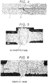
- FIG. 4 is a microphotograph showing a cross section of the welded part of the steel plate after the welding process.
- FIG. 7 shows a graph showing distributions of the Vickers hardness at and near the welded part of the steel plate after the welding process.
- FIG. 6 is a microphotograph showing a cross section of the welded part of the steel plate after the welding process.
- FIG. 7 shows a graph showing distributions of the Vickers hardness at and near the welded part of the steel plate after the welding process.
- a dendritic phase occurred in the welded part after butt welding.
- a dendrite phase occurred in the welded part of the comparative example and the Vickers hardness at and near the welded part was low, and there was variation in the Vickers hardness at and near the welded part.
- the hardness of the joined parts became uniform.
- the ring of the example was heated at 700°C and air-cooled, the hardness of the joined parts was the same as that of the steel plate, and the hardness became uniform throughout the endless metal ring.
Landscapes
- Chemical & Material Sciences (AREA)
- Engineering & Computer Science (AREA)
- Mechanical Engineering (AREA)
- Materials Engineering (AREA)
- Metallurgy (AREA)
- Organic Chemistry (AREA)
- Physics & Mathematics (AREA)
- Thermal Sciences (AREA)
- Crystallography & Structural Chemistry (AREA)
- Heat Treatment Of Articles (AREA)
Abstract
Description
- The present invention relates to a method of producing an endless metal ring.
- As a continuously variable transmission (CVT), a belt type CVT is known. As a power transmission belt for a belt type CVT, an endless metal belt including a belt member formed by stacking metal rings and a plurality of elements supported by the belt member is known. The belt member receives tension, bending stress, a frictional force, and the like during power transmission. Therefore, the belt member and the metal rings constituting the belt member are required to have characteristics such as strength and anti-friction properties, and various examinations have been performed. The metal ring for a belt member is generally processed into a ring shape by welding ends of a steel plate.
- In Japanese Unexamined Patent Application Publication No.
2011-195861 JP 2011-195861 A JP 2011-195861 A - Japanese Unexamined Patent Application Publication No.
2012-250266 JP 2012-250266 A - Japanese Unexamined Patent Application Publication No.
2015-120200 JP 2015-120200 A JP 2015-120200 A - In addition, in Japanese Unexamined Patent Application Publication No.
H02-25281 JP 02-25281 A S61-176479 JP 61-176479 A - When a steel plate containing about 0.30 to 0.70% of carbon is welded, a dendritic phase having a dendritic form (branching form) is likely to be formed in a welded part. Thus, it is known that heating is performed at an austenite transformation temperature or higher to homogenize the steel plate after welding (for example,
JP 2011-195861 A JP 2011-195861 A - The present invention provides a method of producing an endless metal ring in which constriction in a welded part is reduced, the method eliminating the need of performing a heat treatment at a temperature that is equal to or higher than an austenite transformation temperature as a heat treatment for homogenizing the hardness after welding, thereby providing excellent productivity.
- A first aspect of the present invention relates to a method of producing an endless metal ring by butting and welding ends of a steel plate having a chemical composition including 0.30 to 0.70% by mass of C, 2.50% by mass or less of Si, 1.00% by mass or less of Mn, 1.00 to 4.00% by mass of Cr, 0.50 to 3.00% by mass of Mo, and 1.00% by mass or less of V, the chemical composition satisfying a relationship of Formula 1, and a remainder of the chemical composition including Fe and unavoidable impurities. The Formula 1 is 159 × C (%) + 91 × Si (%) + 68 × Cr (%) + 198 × Mo (%) + 646 ≥ 1000. The production method includes a welding process in which, while the ends of the steel plate are heated at a temperature lower than a melting temperature, the ends are pressed against each other and welded by butt welding; and a heat treatment process in which heating is performed at an austenite transformation temperature or lower after the welding process.
- The method of producing an endless metal ring according to the above aspect may include a process of removing a protruding part after the welding process.
- In the method of producing an endless metal ring according to the above aspect, the process of removing the protruding part may be performed after the heat treatment process.
- A second aspect of the present invention relates to a method of producing an endless metal ring by butting and welding ends of a steel plate having a chemical composition including 0.30 to 0.70% by mass of C, 2.50% by mass or less of Si, 1.00% by mass or less of Mn, 1.00 to 4.00% by mass of Cr, 0.50 to 3.00% by mass of Mo, and 1.00% by mass or less of V, the chemical composition satisfying a relationship of Formula 1, and a remainder of the chemical composition including Fe and unavoidable impurities. The Formula 1 is 159 × C (%) + 91 × Si (%) + 68 × Cr (%) + 198 × Mo (%) + 646 ≥ 1000. The production method includes a welding process in which, while the ends of the steel plate are heated at a melting temperature or higher, the ends are pressed against each other such that a melted part as a protruding part is extruded, and the ends are welded by butt welding; and a heat treatment process in which heating is performed at an austenite transformation temperature or lower after the welding process.
- The method of producing an endless metal ring according to the above aspect may include a process of removing the protruding part after the welding process.
- In the method of producing an endless metal ring according to the above aspect, the process of removing the protruding part may be performed after the heat treatment process.
- According to the above aspect of the present invention, is it possible to provide a method of producing an endless metal ring in which constriction in a welded part is reduced, the method eliminating the need of performing a heat treatment at a temperature that is equal to or higher than an austenite transformation temperature as a heat treatment for homogenizing the hardness after welding, thereby providing excellent productivity.
- Features, advantages, and technical and industrial significance of exemplary embodiments of the invention will be described below with reference to the accompanying drawings, in which like numerals denote like elements, and wherein:
-
FIG. 1 is a flowchart showing an example of a method of producing an endless metal ring of the present embodiment; -
FIG. 2 is a schematic process drawing showing an example of a welding process; -
FIG. 3 is a schematic diagram schematically showing an example of butt welding of the present embodiment; -
FIG. 4 is a photograph of a side surface of a steel plate after the welding process; -
FIG. 5 is a microphotograph showing a cross section of a welded part of a steel plate after a welding process according to an example; -
FIG. 6 is a microphotograph showing a cross section of a welded part of a steel plate after a welding process according to a comparative example; and -
FIG. 7 is a graph showing distributions of the Vickers hardness at and near the welded parts of the steel plates after the welding process according to the example and the comparative example. - A steel plate used in a method of producing an endless metal ring of the present embodiment will be described. The steel plate used in the present embodiment is a steel plate having a chemical composition which includes 0.30 to 0.70% by mass of C, 2.50% by mass or less of Si, 1.00% by mass or less of Mn, 1.00 to 4.00% by mass of Cr, 0.50 to 3.00% by mass of Mo, and 1.00% by mass or less of V. The chemical composition satisfies the relationship of Formula 1. The Formula 1 is 159 × C (%) + 91 × Si (%) + 68 × Cr (%) + 198 × Mo (%) + 646 ≥ 1000. The remainder of the chemical composition includes Fe and unavoidable impurities. With the steel plate, it is possible to obtain an endless metal ring having excellent tensile strength. The chemical composition of the steel plate will be described below.
- A content of C (carbon) is set to 0.30% or more in order to secure the strength and toughness. On the other hand, a content of C is set to 0.70% or less in order to reduce a decrease in ductility and toughness due to formation of coarse carbides.
- A content of Si (silicon) is set to 2.5% or less in order to reduce a decrease in ductility and deterioration of nitriding properties. On the other hand, the content of Si may be 0.10% or more in order to increase the strength.
- A content of Mn (manganese) is set to 1.00% or less in order to reduce a decrease in ductility. On the other hand, the content of Mn may be 0.10% or more in order to increase the strength.
- A content of Cr (chromium) is set to 1.00% or more in order to increase the strength and improve nitriding properties. On the other hand, when a content of Cr increases, nitriding properties rather deteriorate, and a nitriding treatment becomes difficult. Therefore, the content is set to 4.00% or less.
- When a content of Mo (molybdenum) is set to 0.5% or more, it is possible to improve the strength and toughness without degrading the ductility. On the other hand, when the content is 3.00% or less, a sufficient effect of improving the strength and toughness is obtained.
- A content of V (vanadium) may be 0.1% or more in order to refine the grain size (i.e., to reduce the grain size to a minute size) and improve the strength and toughness. On the other hand, in order to reduce the amount of coarse carbides and reduce a decrease in the strength and toughness, a content of V is set to 1.0% or less.
- The steel plate may further contain Ni. When Ni is contained, it is possible to reduce generation of carbides and improve the strength and toughness. When Ni is contained, a content thereof is preferably 4.0% or less and more preferably 2.0% or less.

- When the chemical composition of the steel plate satisfies
Formula 1, the steel plate becomes a metal ring having excellent metal fatigue strength characteristics and excellent fatigue life. - In the steel plate, the remainder other than the above elements includes Fe and unavoidable impurities. The unavoidable impurities are elements that are inevitably mixed due to raw materials or a production process. The kinds of elements of the unavoidable impurities are not particularly limited, and include, for example, S (sulfur), P (phosphorus), N (nitrogen), O (oxygen), Al (aluminum), and Ti (titanium).
- In the present embodiment, the width W (refer to
FIG. 2 ) of the steel plate may be adjusted to the width of a continuously variable transmission (CVT) belt to be produced or may be larger than the width of a CVT belt to be produced. When a steel plate having a larger width than the width of the CVT belt is used, a cutting process may be provided when the CVT belt is produced, and the width of the steel plate may be adjusted to the width of the CVT belt. According to the production method of the present embodiment, since constriction in a welded part is reduced, it is possible to produce a CVT belt having excellent strength even with adjustment to a predetermined width of the CVT belt. In the present embodiment, the length L (refer toFIG. 2 ) of the steel plate may be appropriately adjusted according to a CVT belt to be produced. In addition, in the present embodiment, the thickness of the steel plate may be appropriately adjusted according to application purposes and the like and is not particularly limited. For example, the thickness may be 100 µm or more and 200 µm or less. - A method of producing an endless metal belt will be described with reference to
FIG. 1. FIG. 1 is a flowchart showing an example of a method of producing an endless metal ring of the present embodiment. The method of producing an endless metal belt shown in the example inFIG. 1 includes at least a welding process (S11) in which ends of the steel plate are butted against each other, and the butted part is welded to form a ring shape, and a heat treatment process (S12) in which the ring-shaped steel plate is heated at an austenite transformation temperature or lower. Further, a process of removing a protruding part may be provided after the heat treatment process, and additionally, a cutting process and the like may be provided as necessary. The above processes will be described below. - The welding process will be described with reference to
FIG. 2. FIG. 2 is a schematic process drawing showing an example of the welding process. In the example inFIG. 2 , first, a belt-shapedsteel plate 1 whose width W is adjusted for a CVT belt is prepared ((a) inFIG. 2 ). Next, while the steel plate is bent into a ring shape, one end A and the other end B of the steel plate are butted against each other ((b) and (c) inFIG. 2 ). Next, the ends are pressed against each other and welded by butt welding ((d) inFIG. 2 ). For the belt-shaped steel plate, for example, an elongated steel plate may be cut to have a predetermined size, and the steel plate produced in a predetermined size may be used. The steel plate can be bent using, for example, a roll or a mold. - Next, butt welding in the present embodiment will be described in detail with reference to
FIG. 3. FIG. 3 is a schematic diagram schematically showing an example of butt welding in the present embodiment. (a) inFIG. 3 is a diagram showing a state in which one end A and the other end B of the steel plate are butted against each other, and (b) inFIG. 3 is a diagram showing a state when welding is completed. Here, apower supply unit 13 is omitted in (b) inFIG. 3 . In the example inFIG. 3 , one end A of the steel plate is inserted into a fixedelectrode 11 and the other end B of the steel plate is inserted into amovable electrode 12 that is movable in a horizontal direction. Here, the heights of the fixedelectrode 11 and themovable electrode 12 are aligned (i.e., the heights of the fixedelectrode 11 and themovable electrode 12 are the same). A force F is applied to themovable electrode 12 in a direction toward the fixedelectrode 11 in advance. When a voltage is applied from thepower supply unit 13, buttedparts 2 are heated. - There are two embodiments of the method of producing an endless metal ring according to a heating temperature. The first embodiment of butt welding (resistance butt welding) is a method in which, while ends of the steel plate are heated at a temperature lower than a melting temperature, the ends are pressed against each other and welded. According to the first embodiment, since no dendritic phase is formed in the welded part, a process of heating at an austenite transformation temperature or higher for homogenizing is not necessary. According to the butt welding, since surface tension does not occur in the welded part, constriction in the welded part is reduced. The temperature lower than the melting temperature is a temperature preset according to a chemical composition of the steel plate, and is preferably a temperature that is higher than a softening point and lower than a melting point. The temperature of the ends of the steel plate may be directly measured, and a voltage of the
power supply unit 13 for achieving a predetermined temperature and a heating time may be set in advance. When the ends of the steel plate are softened, themovable electrode 12 moves, andbutted parts 2 are joined. It is possible to stably obtain a ring with a predetermined length by setting a voltage such that the voltage is turned off when the moving distance ΔL of themovable electrode 12 reaches a predetermined value. For example, a limit switch which may have a sub motor can be used to set a voltage such that the voltage is automatically turned off when the moving distance ΔL reaches a predetermined value. - The second embodiment of butt welding (resistance butt welding) is a method in which, while the ends of the steel plate are heated at a melting temperature or higher, the ends are pressed against each other and subjected to welding, and a melted part as a protruding part is extruded. According to the second embodiment, since a melted part in which a dendritic phase is formed is extruded as a protruding part, when the protruding part is removed, it is possible to form an endless metal ring having no dendritic phase, and a process of heating at an austenite transformation temperature or higher and homogenizing is not necessary. The temperature that is equal to or higher than the melting temperature is a temperature preset according to a chemical composition of the steel plate and is preferably set to a temperature close to a melting start temperature. The temperature of the ends of the steel plate may be directly measured, and a voltage of the
power supply unit 13 for achieving a predetermined temperature and a heating time may be set in advance. When the temperature of the ends of the steel plate reaches a predetermined temperature, a force F applied to themovable electrode 12 increases andbutted parts 2 are joined. It is possible to stably obtain a ring with a predetermined length by setting a voltage such that the voltage is turned off when the moving distance ΔL of themovable electrode 12 reaches a predetermined value. - Since each of the rings welded according to the butt welding of the first embodiment and the second embodiment has a protruding part in a welded
part 3 as shown inFIG. 4 , generally, a process of removing a protruding part is provided in order to make the thickness of the ring constant. The process of removing a protruding part may be provided before or after a heat treatment process to be described below as long as it is performed after the welding process. In the present embodiment, the process of removing a protruding part may be performed after the heat treatment process to be described below. The method of removing a protruding part may be polishing using a grindstone or barrel polishing, or may be a method of scraping off a protruding part using a cutting tool such as a plane (tool). - Next, the heat treatment process in which the ring-shaped steel plate after the welding process is heated at an austenite transformation temperature or lower is performed. Since the ring-shaped steel plate obtained in the above welding process does not have a dendritic phase at least at a part of the ring thickness, when it is heated at an austenite transformation temperature or lower, the hardness of the entire ring can be changed to a uniform hardness at which rolling is possible. The heat treatment temperature is not particularly limited as long as it is the austenite transformation temperature or lower, and preferably, for example, 640°C to 750°C. The heat treatment time may be, for example, 0.5 to 3 hours.
- The endless metal ring obtained by the method of producing an endless metal ring of the present embodiment can be used as a component (material) of an endless metal belt member for CVT. For example, the endless metal belt member can be produced by rolling and quenching an endless metal ring and adjusting its circumferential length, and additionally, performing a nitriding treatment and the like as necessary.
- The present invention will be described below in detail with reference to an example and a comparative example. However, the present invention is not limited by these descriptions.
- A belt-shaped steel plate having a chemical composition including 0.30 to 0.70% by mass of C, 2.50% by mass or less of Si, 1.00% by mass or less of Mn, 1.00 to 4.00% by mass of Cr, 0.50 to 3.00% by mass of Mo, and 1.00% by mass or less of V was prepared. The chemical composition satisfies the relationship of
Formula 1.Formula 1 is 159 × C (%) + 91 × Si (%) + 68 × Cr (%) + 198 × Mo (%) + 646 ≥1000. The remainder of the chemical composition includes Fe and unavoidable impurities. Next, according to the examples inFIG. 2 andFIG. 3 , while ends of the steel plate were heated at a temperature lower than a melting temperature, the ends were pressed against each other and subjected to butt welding (resistance butt welding). As shown inFIG. 4 , the obtained weldedpart 3 had a burr (protruding part). The ring-shaped steel plate after welding was heated at 700°C for 1 hour, and air-cooled. Then, the burr was removed using a cutting tool such as a plane (tool) and thereby an endless metal ring was obtained.FIG. 5 is a microphotograph showing a cross section of the welded part of the steel plate after the welding process. In addition,FIG. 7 shows a graph showing distributions of the Vickers hardness at and near the welded part of the steel plate after the welding process. - An endless metal ring of a comparative example was obtained in the same manner as in the example except that, while ends of a steel plate were heated at a temperature higher than a melting temperature, the ends were pressed against each other slowly and subjected to butt welding.
FIG. 6 is a microphotograph showing a cross section of the welded part of the steel plate after the welding process. In addition,FIG. 7 shows a graph showing distributions of the Vickers hardness at and near the welded part of the steel plate after the welding process. - As shown in
FIG. 6 , in the production method of the comparative example, a dendritic phase occurred in the welded part after butt welding. In addition, as shown inFIG. 7 , a dendrite phase occurred in the welded part of the comparative example and the Vickers hardness at and near the welded part was low, and there was variation in the Vickers hardness at and near the welded part. On the other hand, in the production method of the example of the present invention, since the welded part was completely quenched after welding, the hardness of the joined parts became uniform. When the ring of the example was heated at 700°C and air-cooled, the hardness of the joined parts was the same as that of the steel plate, and the hardness became uniform throughout the endless metal ring.
Claims (6)
- A method of producing an endless metal ring by butting and welding ends of a steel plate (1) having a chemical composition including 0.30 to 0.70% by mass of C, 2.50% by mass or less of Si, 1.00% by mass or less of Mn, 1.00 to 4.00% by mass of Cr, 0.50 to 3.00% by mass of Mo, and 1.00% by mass or less of V, the chemical composition satisfying a relationship of Formula 1, and a remainder of the chemical composition including Fe and unavoidable impurities, wherein the Formula 1 is 159 × C (%) + 91 × Si (%) + 68 × Cr (%) + 198 × Mo (%) + 646 ≥ 1000, the method comprising:a welding process in which, while the ends of the steel plate (1) are heated at a temperature lower than a melting temperature, the ends are pressed against each other and welded by butt welding; anda heat treatment process in which heating is performed at an austenite transformation temperature or lower after the welding process.
- The method according to claim 1, further comprising:
a process of removing a protruding part after the welding process. - The method according to claim 2, wherein the process of removing the protruding part is performed after the heat treatment process.
- A method of producing an endless metal ring by butting and welding ends of a steel plate (1) having a chemical composition including 0.30 to 0.70% by mass of C, 2.50% by mass or less of Si, 1.00% by mass or less of Mn, 1.00 to 4.00% by mass of Cr, 0.50 to 3.00% by mass of Mo, and 1.00% by mass or less of V, the chemical composition satisfying a relationship of Formula 1, and a remainder of the chemical composition including Fe and unavoidable impurities, wherein the Formula 1 is 159 × C (%) + 91 × Si (%) + 68 × Cr (%) + 198 × Mo (%) + 646 ≥ 1000, the method comprising:a welding process in which, while the ends of the steel plate (1) are heated at a melting temperature or higher, the ends are pressed against each other such that a melted part as a protruding part is extruded, and the ends are welded by butt welding; anda heat treatment process in which heating is performed at an austenite transformation temperature or lower after the welding process.
- The method according to claim 4, further comprising:
a process of removing the protruding part after the welding process. - The method according to claim 5, wherein the process of removing the protruding part is performed after the heat treatment process.
Applications Claiming Priority (1)
| Application Number | Priority Date | Filing Date | Title |
|---|---|---|---|
| JP2018068838A JP2019177403A (en) | 2018-03-30 | 2018-03-30 | Manufacturing method of endless metal ring |
Publications (2)
| Publication Number | Publication Date |
|---|---|
| EP3546601A1 true EP3546601A1 (en) | 2019-10-02 |
| EP3546601B1 EP3546601B1 (en) | 2020-08-12 |
Family
ID=65686781
Family Applications (1)
| Application Number | Title | Priority Date | Filing Date |
|---|---|---|---|
| EP19160691.2A Not-in-force EP3546601B1 (en) | 2018-03-30 | 2019-03-05 | Method of producing endless metal ring |
Country Status (3)
| Country | Link |
|---|---|
| US (1) | US10960486B2 (en) |
| EP (1) | EP3546601B1 (en) |
| JP (1) | JP2019177403A (en) |
Citations (8)
| Publication number | Priority date | Publication date | Assignee | Title |
|---|---|---|---|---|
| JPS61176479A (en) | 1985-02-01 | 1986-08-08 | Toyota Motor Corp | Method and device for butt resistance welding of thin plate |
| JPH0225281A (en) | 1988-07-12 | 1990-01-26 | Kanai Hiroyuki | Production of endless metallic band |
| JP2011195861A (en) | 2010-03-18 | 2011-10-06 | Aichi Steel Works Ltd | Belt for continuously variable transmission and steel therefor |
| JP2012250266A (en) | 2011-06-03 | 2012-12-20 | Toyota Motor Corp | Method for manufacturing metal ring |
| JP2015120200A (en) | 2013-12-24 | 2015-07-02 | ローベルト ボツシユ ゲゼルシヤフト ミツト ベシユレンクテル ハフツングRobert Bosch Gmbh | Method for forming carrier ring suitable for use in drive belt for continuously variable transmission |
| EP3081661A1 (en) * | 2013-12-12 | 2016-10-19 | Aichi Steel Corporation | Ring member for cvt and method for producing same |
| JP2018172751A (en) * | 2017-03-31 | 2018-11-08 | 愛知製鋼株式会社 | Cvt ring material for nitriding, and cvt ring member, and method for manufacturing the same |
| WO2018221646A1 (en) * | 2017-06-02 | 2018-12-06 | アイシン・エィ・ダブリュ株式会社 | Endless ring production method |
Family Cites Families (5)
| Publication number | Priority date | Publication date | Assignee | Title |
|---|---|---|---|---|
| US3619547A (en) * | 1969-12-18 | 1971-11-09 | Torin Corp | Preheating and welding method for bearing races and other articles |
| JPH0924435A (en) * | 1995-07-10 | 1997-01-28 | Sumitomo Electric Ind Ltd | Method and device for automatic terminal connection of linear object |
| JP2000317642A (en) * | 1999-05-14 | 2000-11-21 | Sumitomo Metal Ind Ltd | Flash butt welding of high carbon steel sheet or strip |
| JP5768746B2 (en) * | 2012-03-16 | 2015-08-26 | トヨタ自動車株式会社 | Manufacturing method of endless metal ring |
| JP6036574B2 (en) * | 2013-06-25 | 2016-11-30 | トヨタ自動車株式会社 | Manufacturing method of laminated ring |
-
2018
- 2018-03-30 JP JP2018068838A patent/JP2019177403A/en active Pending
-
2019
- 2019-03-05 EP EP19160691.2A patent/EP3546601B1/en not_active Not-in-force
- 2019-03-12 US US16/299,253 patent/US10960486B2/en not_active Expired - Fee Related
Patent Citations (8)
| Publication number | Priority date | Publication date | Assignee | Title |
|---|---|---|---|---|
| JPS61176479A (en) | 1985-02-01 | 1986-08-08 | Toyota Motor Corp | Method and device for butt resistance welding of thin plate |
| JPH0225281A (en) | 1988-07-12 | 1990-01-26 | Kanai Hiroyuki | Production of endless metallic band |
| JP2011195861A (en) | 2010-03-18 | 2011-10-06 | Aichi Steel Works Ltd | Belt for continuously variable transmission and steel therefor |
| JP2012250266A (en) | 2011-06-03 | 2012-12-20 | Toyota Motor Corp | Method for manufacturing metal ring |
| EP3081661A1 (en) * | 2013-12-12 | 2016-10-19 | Aichi Steel Corporation | Ring member for cvt and method for producing same |
| JP2015120200A (en) | 2013-12-24 | 2015-07-02 | ローベルト ボツシユ ゲゼルシヤフト ミツト ベシユレンクテル ハフツングRobert Bosch Gmbh | Method for forming carrier ring suitable for use in drive belt for continuously variable transmission |
| JP2018172751A (en) * | 2017-03-31 | 2018-11-08 | 愛知製鋼株式会社 | Cvt ring material for nitriding, and cvt ring member, and method for manufacturing the same |
| WO2018221646A1 (en) * | 2017-06-02 | 2018-12-06 | アイシン・エィ・ダブリュ株式会社 | Endless ring production method |
Also Published As
| Publication number | Publication date |
|---|---|
| US10960486B2 (en) | 2021-03-30 |
| JP2019177403A (en) | 2019-10-17 |
| EP3546601B1 (en) | 2020-08-12 |
| US20190299322A1 (en) | 2019-10-03 |
Similar Documents
| Publication | Publication Date | Title |
|---|---|---|
| EP1477574B1 (en) | High-strength stainless steel sheet and method for manufacturing the same | |
| JP2009299189A (en) | High carbon steel sheet for precision blanking | |
| US10948046B2 (en) | CVT ring member and method for manufacturing the same | |
| JP5418544B2 (en) | High strength, high fatigue strength thin steel strip, endless steel strip and method for producing the same | |
| JP5817921B2 (en) | Endless metal ring manufacturing method and manufacturing apparatus | |
| CN110885978B (en) | Method for strengthening working belt of aluminum profile extrusion hot-working die | |
| EP3546601B1 (en) | Method of producing endless metal ring | |
| JP2019039056A (en) | Steel sheet and production method of steel sheet | |
| JP5768746B2 (en) | Manufacturing method of endless metal ring | |
| US7459034B2 (en) | Steel hoop made from a martensitic steel strip | |
| JP5973244B2 (en) | Manufacturing method of endless metal ring | |
| JP2018172749A (en) | Steel for cvt ring, and cvt ring material for nitriding, and method for manufacturing the same, and cvt ring member and method for manufacturing the same | |
| CA3030455A1 (en) | Method for the in-line manufacturing of steel tube | |
| JP2018172751A (en) | Cvt ring material for nitriding, and cvt ring member, and method for manufacturing the same | |
| EP3560621A1 (en) | Endless metal ring and method of producing the same | |
| US10260123B2 (en) | Rolled steel bar for machine structural use and method of producing the same | |
| WO2020158017A1 (en) | Carbon alloy steel sheet and method for producing carbon alloy steel sheet | |
| JPH08260093A (en) | Metal band saw barrel material excellent in fatigue strength in weld zone and metal band saw | |
| MX2008009551A (en) | HOT-WRAPPED MICRO-ALLOY STEEL FLEJE FOR OBTAINING PARTS ENDED BY PRESSURE OR COLD SHEARING. | |
| EP3399067A1 (en) | Steel sheet for tool and manufacturing method therefor | |
| JP2018172754A (en) | Cvt ring material for nitriding, cvt ring member, and method for manufacturing the same | |
| JP2019119898A (en) | Cvt ring raw material, cvt ring member, and manufacturing method therefor | |
| JP2019119899A (en) | Cvt ring raw material, cvt ring member, and manufacturing method therefor | |
| JP3475987B2 (en) | Manufacturing method of high toughness hot rolled steel strip with excellent homogeneity and fatigue properties | |
| WO2002085548A1 (en) | Production method of belt for stainless steel continuously variable transmission belt |
Legal Events
| Date | Code | Title | Description |
|---|---|---|---|
| PUAI | Public reference made under article 153(3) epc to a published international application that has entered the european phase |
Free format text: ORIGINAL CODE: 0009012 |
|
| STAA | Information on the status of an ep patent application or granted ep patent |
Free format text: STATUS: REQUEST FOR EXAMINATION WAS MADE |
|
| 17P | Request for examination filed |
Effective date: 20190305 |
|
| AK | Designated contracting states |
Kind code of ref document: A1 Designated state(s): AL AT BE BG CH CY CZ DE DK EE ES FI FR GB GR HR HU IE IS IT LI LT LU LV MC MK MT NL NO PL PT RO RS SE SI SK SM TR |
|
| AX | Request for extension of the european patent |
Extension state: BA ME |
|
| GRAP | Despatch of communication of intention to grant a patent |
Free format text: ORIGINAL CODE: EPIDOSNIGR1 |
|
| STAA | Information on the status of an ep patent application or granted ep patent |
Free format text: STATUS: GRANT OF PATENT IS INTENDED |
|
| INTG | Intention to grant announced |
Effective date: 20200331 |
|
| GRAS | Grant fee paid |
Free format text: ORIGINAL CODE: EPIDOSNIGR3 |
|
| GRAA | (expected) grant |
Free format text: ORIGINAL CODE: 0009210 |
|
| STAA | Information on the status of an ep patent application or granted ep patent |
Free format text: STATUS: THE PATENT HAS BEEN GRANTED |
|
| AK | Designated contracting states |
Kind code of ref document: B1 Designated state(s): AL AT BE BG CH CY CZ DE DK EE ES FI FR GB GR HR HU IE IS IT LI LT LU LV MC MK MT NL NO PL PT RO RS SE SI SK SM TR |
|
| RAP1 | Party data changed (applicant data changed or rights of an application transferred) |
Owner name: TOYOTA JIDOSHA KABUSHIKI KAISHA |
|
| REG | Reference to a national code |
Ref country code: CH Ref legal event code: EP |
|
| REG | Reference to a national code |
Ref country code: DE Ref legal event code: R096 Ref document number: 602019000440 Country of ref document: DE |
|
| REG | Reference to a national code |
Ref country code: IE Ref legal event code: FG4D |
|
| REG | Reference to a national code |
Ref country code: AT Ref legal event code: REF Ref document number: 1301615 Country of ref document: AT Kind code of ref document: T Effective date: 20200915 |
|
| REG | Reference to a national code |
Ref country code: NL Ref legal event code: FP |
|
| REG | Reference to a national code |
Ref country code: LT Ref legal event code: MG4D |
|
| PG25 | Lapsed in a contracting state [announced via postgrant information from national office to epo] |
Ref country code: FI Free format text: LAPSE BECAUSE OF FAILURE TO SUBMIT A TRANSLATION OF THE DESCRIPTION OR TO PAY THE FEE WITHIN THE PRESCRIBED TIME-LIMIT Effective date: 20200812 Ref country code: LT Free format text: LAPSE BECAUSE OF FAILURE TO SUBMIT A TRANSLATION OF THE DESCRIPTION OR TO PAY THE FEE WITHIN THE PRESCRIBED TIME-LIMIT Effective date: 20200812 Ref country code: HR Free format text: LAPSE BECAUSE OF FAILURE TO SUBMIT A TRANSLATION OF THE DESCRIPTION OR TO PAY THE FEE WITHIN THE PRESCRIBED TIME-LIMIT Effective date: 20200812 Ref country code: NO Free format text: LAPSE BECAUSE OF FAILURE TO SUBMIT A TRANSLATION OF THE DESCRIPTION OR TO PAY THE FEE WITHIN THE PRESCRIBED TIME-LIMIT Effective date: 20201112 Ref country code: BG Free format text: LAPSE BECAUSE OF FAILURE TO SUBMIT A TRANSLATION OF THE DESCRIPTION OR TO PAY THE FEE WITHIN THE PRESCRIBED TIME-LIMIT Effective date: 20201112 Ref country code: SE Free format text: LAPSE BECAUSE OF FAILURE TO SUBMIT A TRANSLATION OF THE DESCRIPTION OR TO PAY THE FEE WITHIN THE PRESCRIBED TIME-LIMIT Effective date: 20200812 Ref country code: GR Free format text: LAPSE BECAUSE OF FAILURE TO SUBMIT A TRANSLATION OF THE DESCRIPTION OR TO PAY THE FEE WITHIN THE PRESCRIBED TIME-LIMIT Effective date: 20201113 |
|
| REG | Reference to a national code |
Ref country code: AT Ref legal event code: MK05 Ref document number: 1301615 Country of ref document: AT Kind code of ref document: T Effective date: 20200812 |
|
| PG25 | Lapsed in a contracting state [announced via postgrant information from national office to epo] |
Ref country code: RS Free format text: LAPSE BECAUSE OF FAILURE TO SUBMIT A TRANSLATION OF THE DESCRIPTION OR TO PAY THE FEE WITHIN THE PRESCRIBED TIME-LIMIT Effective date: 20200812 Ref country code: LV Free format text: LAPSE BECAUSE OF FAILURE TO SUBMIT A TRANSLATION OF THE DESCRIPTION OR TO PAY THE FEE WITHIN THE PRESCRIBED TIME-LIMIT Effective date: 20200812 Ref country code: PL Free format text: LAPSE BECAUSE OF FAILURE TO SUBMIT A TRANSLATION OF THE DESCRIPTION OR TO PAY THE FEE WITHIN THE PRESCRIBED TIME-LIMIT Effective date: 20200812 Ref country code: IS Free format text: LAPSE BECAUSE OF FAILURE TO SUBMIT A TRANSLATION OF THE DESCRIPTION OR TO PAY THE FEE WITHIN THE PRESCRIBED TIME-LIMIT Effective date: 20201212 |
|
| PG25 | Lapsed in a contracting state [announced via postgrant information from national office to epo] |
Ref country code: SM Free format text: LAPSE BECAUSE OF FAILURE TO SUBMIT A TRANSLATION OF THE DESCRIPTION OR TO PAY THE FEE WITHIN THE PRESCRIBED TIME-LIMIT Effective date: 20200812 Ref country code: RO Free format text: LAPSE BECAUSE OF FAILURE TO SUBMIT A TRANSLATION OF THE DESCRIPTION OR TO PAY THE FEE WITHIN THE PRESCRIBED TIME-LIMIT Effective date: 20200812 Ref country code: DK Free format text: LAPSE BECAUSE OF FAILURE TO SUBMIT A TRANSLATION OF THE DESCRIPTION OR TO PAY THE FEE WITHIN THE PRESCRIBED TIME-LIMIT Effective date: 20200812 Ref country code: CZ Free format text: LAPSE BECAUSE OF FAILURE TO SUBMIT A TRANSLATION OF THE DESCRIPTION OR TO PAY THE FEE WITHIN THE PRESCRIBED TIME-LIMIT Effective date: 20200812 Ref country code: EE Free format text: LAPSE BECAUSE OF FAILURE TO SUBMIT A TRANSLATION OF THE DESCRIPTION OR TO PAY THE FEE WITHIN THE PRESCRIBED TIME-LIMIT Effective date: 20200812 |
|
| REG | Reference to a national code |
Ref country code: DE Ref legal event code: R097 Ref document number: 602019000440 Country of ref document: DE |
|
| PG25 | Lapsed in a contracting state [announced via postgrant information from national office to epo] |
Ref country code: AL Free format text: LAPSE BECAUSE OF FAILURE TO SUBMIT A TRANSLATION OF THE DESCRIPTION OR TO PAY THE FEE WITHIN THE PRESCRIBED TIME-LIMIT Effective date: 20200812 Ref country code: AT Free format text: LAPSE BECAUSE OF FAILURE TO SUBMIT A TRANSLATION OF THE DESCRIPTION OR TO PAY THE FEE WITHIN THE PRESCRIBED TIME-LIMIT Effective date: 20200812 Ref country code: ES Free format text: LAPSE BECAUSE OF FAILURE TO SUBMIT A TRANSLATION OF THE DESCRIPTION OR TO PAY THE FEE WITHIN THE PRESCRIBED TIME-LIMIT Effective date: 20200812 |
|
| PLBE | No opposition filed within time limit |
Free format text: ORIGINAL CODE: 0009261 |
|
| STAA | Information on the status of an ep patent application or granted ep patent |
Free format text: STATUS: NO OPPOSITION FILED WITHIN TIME LIMIT |
|
| PG25 | Lapsed in a contracting state [announced via postgrant information from national office to epo] |
Ref country code: SK Free format text: LAPSE BECAUSE OF FAILURE TO SUBMIT A TRANSLATION OF THE DESCRIPTION OR TO PAY THE FEE WITHIN THE PRESCRIBED TIME-LIMIT Effective date: 20200812 |
|
| 26N | No opposition filed |
Effective date: 20210514 |
|
| PG25 | Lapsed in a contracting state [announced via postgrant information from national office to epo] |
Ref country code: IT Free format text: LAPSE BECAUSE OF FAILURE TO SUBMIT A TRANSLATION OF THE DESCRIPTION OR TO PAY THE FEE WITHIN THE PRESCRIBED TIME-LIMIT Effective date: 20200812 |
|
| PG25 | Lapsed in a contracting state [announced via postgrant information from national office to epo] |
Ref country code: SI Free format text: LAPSE BECAUSE OF FAILURE TO SUBMIT A TRANSLATION OF THE DESCRIPTION OR TO PAY THE FEE WITHIN THE PRESCRIBED TIME-LIMIT Effective date: 20200812 |
|
| PG25 | Lapsed in a contracting state [announced via postgrant information from national office to epo] |
Ref country code: MC Free format text: LAPSE BECAUSE OF FAILURE TO SUBMIT A TRANSLATION OF THE DESCRIPTION OR TO PAY THE FEE WITHIN THE PRESCRIBED TIME-LIMIT Effective date: 20200812 |
|
| REG | Reference to a national code |
Ref country code: BE Ref legal event code: MM Effective date: 20210331 |
|
| PG25 | Lapsed in a contracting state [announced via postgrant information from national office to epo] |
Ref country code: FR Free format text: LAPSE BECAUSE OF NON-PAYMENT OF DUE FEES Effective date: 20210331 Ref country code: LU Free format text: LAPSE BECAUSE OF NON-PAYMENT OF DUE FEES Effective date: 20210305 Ref country code: IE Free format text: LAPSE BECAUSE OF NON-PAYMENT OF DUE FEES Effective date: 20210305 |
|
| PGFP | Annual fee paid to national office [announced via postgrant information from national office to epo] |
Ref country code: NL Payment date: 20220215 Year of fee payment: 4 |
|
| PG25 | Lapsed in a contracting state [announced via postgrant information from national office to epo] |
Ref country code: BE Free format text: LAPSE BECAUSE OF NON-PAYMENT OF DUE FEES Effective date: 20210331 |
|
| REG | Reference to a national code |
Ref country code: CH Ref legal event code: PL |
|
| PG25 | Lapsed in a contracting state [announced via postgrant information from national office to epo] |
Ref country code: LI Free format text: LAPSE BECAUSE OF NON-PAYMENT OF DUE FEES Effective date: 20220331 Ref country code: CH Free format text: LAPSE BECAUSE OF NON-PAYMENT OF DUE FEES Effective date: 20220331 |
|
| PG25 | Lapsed in a contracting state [announced via postgrant information from national office to epo] |
Ref country code: PT Free format text: LAPSE BECAUSE OF FAILURE TO SUBMIT A TRANSLATION OF THE DESCRIPTION OR TO PAY THE FEE WITHIN THE PRESCRIBED TIME-LIMIT Effective date: 20201214 |
|
| PGFP | Annual fee paid to national office [announced via postgrant information from national office to epo] |
Ref country code: DE Payment date: 20230131 Year of fee payment: 5 |
|
| P01 | Opt-out of the competence of the unified patent court (upc) registered |
Effective date: 20230427 |
|
| PG25 | Lapsed in a contracting state [announced via postgrant information from national office to epo] |
Ref country code: CY Free format text: LAPSE BECAUSE OF FAILURE TO SUBMIT A TRANSLATION OF THE DESCRIPTION OR TO PAY THE FEE WITHIN THE PRESCRIBED TIME-LIMIT Effective date: 20200812 |
|
| PG25 | Lapsed in a contracting state [announced via postgrant information from national office to epo] |
Ref country code: HU Free format text: LAPSE BECAUSE OF FAILURE TO SUBMIT A TRANSLATION OF THE DESCRIPTION OR TO PAY THE FEE WITHIN THE PRESCRIBED TIME-LIMIT; INVALID AB INITIO Effective date: 20190305 |
|
| REG | Reference to a national code |
Ref country code: NL Ref legal event code: MM Effective date: 20230401 |
|
| GBPC | Gb: european patent ceased through non-payment of renewal fee |
Effective date: 20230305 |
|
| PG25 | Lapsed in a contracting state [announced via postgrant information from national office to epo] |
Ref country code: NL Free format text: LAPSE BECAUSE OF NON-PAYMENT OF DUE FEES Effective date: 20230401 |
|
| PG25 | Lapsed in a contracting state [announced via postgrant information from national office to epo] |
Ref country code: GB Free format text: LAPSE BECAUSE OF NON-PAYMENT OF DUE FEES Effective date: 20230305 |
|
| PG25 | Lapsed in a contracting state [announced via postgrant information from national office to epo] |
Ref country code: GB Free format text: LAPSE BECAUSE OF NON-PAYMENT OF DUE FEES Effective date: 20230305 |
|
| PG25 | Lapsed in a contracting state [announced via postgrant information from national office to epo] |
Ref country code: MK Free format text: LAPSE BECAUSE OF FAILURE TO SUBMIT A TRANSLATION OF THE DESCRIPTION OR TO PAY THE FEE WITHIN THE PRESCRIBED TIME-LIMIT Effective date: 20200812 |
|
| PG25 | Lapsed in a contracting state [announced via postgrant information from national office to epo] |
Ref country code: TR Free format text: LAPSE BECAUSE OF FAILURE TO SUBMIT A TRANSLATION OF THE DESCRIPTION OR TO PAY THE FEE WITHIN THE PRESCRIBED TIME-LIMIT Effective date: 20200812 |
|
| PG25 | Lapsed in a contracting state [announced via postgrant information from national office to epo] |
Ref country code: MT Free format text: LAPSE BECAUSE OF FAILURE TO SUBMIT A TRANSLATION OF THE DESCRIPTION OR TO PAY THE FEE WITHIN THE PRESCRIBED TIME-LIMIT Effective date: 20200812 |
|
| REG | Reference to a national code |
Ref country code: DE Ref legal event code: R119 Ref document number: 602019000440 Country of ref document: DE |
|
| PG25 | Lapsed in a contracting state [announced via postgrant information from national office to epo] |
Ref country code: DE Free format text: LAPSE BECAUSE OF NON-PAYMENT OF DUE FEES Effective date: 20241001 |
|
| PG25 | Lapsed in a contracting state [announced via postgrant information from national office to epo] |
Ref country code: DE Free format text: LAPSE BECAUSE OF NON-PAYMENT OF DUE FEES Effective date: 20241001 |