EP3546418A1 - Load-handling vehicle - Google Patents
Load-handling vehicle Download PDFInfo
- Publication number
- EP3546418A1 EP3546418A1 EP19165048.0A EP19165048A EP3546418A1 EP 3546418 A1 EP3546418 A1 EP 3546418A1 EP 19165048 A EP19165048 A EP 19165048A EP 3546418 A1 EP3546418 A1 EP 3546418A1
- Authority
- EP
- European Patent Office
- Prior art keywords
- load
- vehicle
- boom
- battery pack
- handling vehicle
- Prior art date
- Legal status (The legal status is an assumption and is not a legal conclusion. Google has not performed a legal analysis and makes no representation as to the accuracy of the status listed.)
- Granted
Links
Images




Classifications
-
- B—PERFORMING OPERATIONS; TRANSPORTING
- B66—HOISTING; LIFTING; HAULING
- B66F—HOISTING, LIFTING, HAULING OR PUSHING, NOT OTHERWISE PROVIDED FOR, e.g. DEVICES WHICH APPLY A LIFTING OR PUSHING FORCE DIRECTLY TO THE SURFACE OF A LOAD
- B66F9/00—Devices for lifting or lowering bulky or heavy goods for loading or unloading purposes
- B66F9/06—Devices for lifting or lowering bulky or heavy goods for loading or unloading purposes movable, with their loads, on wheels or the like, e.g. fork-lift trucks
- B66F9/075—Constructional features or details
- B66F9/07513—Details concerning the chassis
- B66F9/07531—Battery compartments
-
- B—PERFORMING OPERATIONS; TRANSPORTING
- B60—VEHICLES IN GENERAL
- B60K—ARRANGEMENT OR MOUNTING OF PROPULSION UNITS OR OF TRANSMISSIONS IN VEHICLES; ARRANGEMENT OR MOUNTING OF PLURAL DIVERSE PRIME-MOVERS IN VEHICLES; AUXILIARY DRIVES FOR VEHICLES; INSTRUMENTATION OR DASHBOARDS FOR VEHICLES; ARRANGEMENTS IN CONNECTION WITH COOLING, AIR INTAKE, GAS EXHAUST OR FUEL SUPPLY OF PROPULSION UNITS IN VEHICLES
- B60K1/00—Arrangement or mounting of electrical propulsion units
- B60K1/04—Arrangement or mounting of electrical propulsion units of the electric storage means for propulsion
-
- B—PERFORMING OPERATIONS; TRANSPORTING
- B60—VEHICLES IN GENERAL
- B60L—PROPULSION OF ELECTRICALLY-PROPELLED VEHICLES; SUPPLYING ELECTRIC POWER FOR AUXILIARY EQUIPMENT OF ELECTRICALLY-PROPELLED VEHICLES; ELECTRODYNAMIC BRAKE SYSTEMS FOR VEHICLES IN GENERAL; MAGNETIC SUSPENSION OR LEVITATION FOR VEHICLES; MONITORING OPERATING VARIABLES OF ELECTRICALLY-PROPELLED VEHICLES; ELECTRIC SAFETY DEVICES FOR ELECTRICALLY-PROPELLED VEHICLES
- B60L50/00—Electric propulsion with power supplied within the vehicle
- B60L50/50—Electric propulsion with power supplied within the vehicle using propulsion power supplied by batteries or fuel cells
- B60L50/60—Electric propulsion with power supplied within the vehicle using propulsion power supplied by batteries or fuel cells using power supplied by batteries
- B60L50/66—Arrangements of batteries
-
- B—PERFORMING OPERATIONS; TRANSPORTING
- B66—HOISTING; LIFTING; HAULING
- B66F—HOISTING, LIFTING, HAULING OR PUSHING, NOT OTHERWISE PROVIDED FOR, e.g. DEVICES WHICH APPLY A LIFTING OR PUSHING FORCE DIRECTLY TO THE SURFACE OF A LOAD
- B66F9/00—Devices for lifting or lowering bulky or heavy goods for loading or unloading purposes
- B66F9/06—Devices for lifting or lowering bulky or heavy goods for loading or unloading purposes movable, with their loads, on wheels or the like, e.g. fork-lift trucks
- B66F9/065—Devices for lifting or lowering bulky or heavy goods for loading or unloading purposes movable, with their loads, on wheels or the like, e.g. fork-lift trucks non-masted
- B66F9/0655—Devices for lifting or lowering bulky or heavy goods for loading or unloading purposes movable, with their loads, on wheels or the like, e.g. fork-lift trucks non-masted with a telescopic boom
-
- B—PERFORMING OPERATIONS; TRANSPORTING
- B66—HOISTING; LIFTING; HAULING
- B66F—HOISTING, LIFTING, HAULING OR PUSHING, NOT OTHERWISE PROVIDED FOR, e.g. DEVICES WHICH APPLY A LIFTING OR PUSHING FORCE DIRECTLY TO THE SURFACE OF A LOAD
- B66F9/00—Devices for lifting or lowering bulky or heavy goods for loading or unloading purposes
- B66F9/06—Devices for lifting or lowering bulky or heavy goods for loading or unloading purposes movable, with their loads, on wheels or the like, e.g. fork-lift trucks
- B66F9/075—Constructional features or details
- B66F9/07513—Details concerning the chassis
- B66F9/0754—Battery removal arrangements
-
- B—PERFORMING OPERATIONS; TRANSPORTING
- B60—VEHICLES IN GENERAL
- B60K—ARRANGEMENT OR MOUNTING OF PROPULSION UNITS OR OF TRANSMISSIONS IN VEHICLES; ARRANGEMENT OR MOUNTING OF PLURAL DIVERSE PRIME-MOVERS IN VEHICLES; AUXILIARY DRIVES FOR VEHICLES; INSTRUMENTATION OR DASHBOARDS FOR VEHICLES; ARRANGEMENTS IN CONNECTION WITH COOLING, AIR INTAKE, GAS EXHAUST OR FUEL SUPPLY OF PROPULSION UNITS IN VEHICLES
- B60K1/00—Arrangement or mounting of electrical propulsion units
- B60K1/04—Arrangement or mounting of electrical propulsion units of the electric storage means for propulsion
- B60K2001/0405—Arrangement or mounting of electrical propulsion units of the electric storage means for propulsion characterised by their position
- B60K2001/0416—Arrangement in the rear part of the vehicle
-
- B—PERFORMING OPERATIONS; TRANSPORTING
- B60—VEHICLES IN GENERAL
- B60L—PROPULSION OF ELECTRICALLY-PROPELLED VEHICLES; SUPPLYING ELECTRIC POWER FOR AUXILIARY EQUIPMENT OF ELECTRICALLY-PROPELLED VEHICLES; ELECTRODYNAMIC BRAKE SYSTEMS FOR VEHICLES IN GENERAL; MAGNETIC SUSPENSION OR LEVITATION FOR VEHICLES; MONITORING OPERATING VARIABLES OF ELECTRICALLY-PROPELLED VEHICLES; ELECTRIC SAFETY DEVICES FOR ELECTRICALLY-PROPELLED VEHICLES
- B60L2200/00—Type of vehicles
- B60L2200/40—Working vehicles
-
- B—PERFORMING OPERATIONS; TRANSPORTING
- B60—VEHICLES IN GENERAL
- B60Y—INDEXING SCHEME RELATING TO ASPECTS CROSS-CUTTING VEHICLE TECHNOLOGY
- B60Y2200/00—Type of vehicle
- B60Y2200/10—Road Vehicles
- B60Y2200/15—Fork lift trucks, Industrial trucks
-
- B—PERFORMING OPERATIONS; TRANSPORTING
- B60—VEHICLES IN GENERAL
- B60Y—INDEXING SCHEME RELATING TO ASPECTS CROSS-CUTTING VEHICLE TECHNOLOGY
- B60Y2400/00—Special features of vehicle units
- B60Y2400/11—Electric energy storages
- B60Y2400/112—Batteries
-
- Y—GENERAL TAGGING OF NEW TECHNOLOGICAL DEVELOPMENTS; GENERAL TAGGING OF CROSS-SECTIONAL TECHNOLOGIES SPANNING OVER SEVERAL SECTIONS OF THE IPC; TECHNICAL SUBJECTS COVERED BY FORMER USPC CROSS-REFERENCE ART COLLECTIONS [XRACs] AND DIGESTS
- Y02—TECHNOLOGIES OR APPLICATIONS FOR MITIGATION OR ADAPTATION AGAINST CLIMATE CHANGE
- Y02T—CLIMATE CHANGE MITIGATION TECHNOLOGIES RELATED TO TRANSPORTATION
- Y02T10/00—Road transport of goods or passengers
- Y02T10/60—Other road transportation technologies with climate change mitigation effect
- Y02T10/70—Energy storage systems for electromobility, e.g. batteries
Definitions
- the present invention relates a load-handling vehicle.
- the present invention relates to a compact electric load-handling vehicle suitable for use in warehouses or similar situations where the vehicle is likely to experience restricted manoeuvring space.
- Electric load-handling vehicles are typically equipped with a battery capable of powering the vehicle for a standard eight-hour shift, which is suitable for vehicles used in warehouses that operate during only these hours.
- a battery pack capable of powering the vehicle for a standard eight-hour shift, which is suitable for vehicles used in warehouses that operate during only these hours.
- the battery pack it is possible for the battery pack to be charged in situ, and there is no necessary requirement for the battery pack to be removed from the vehicle.
- many warehouses operate more than 8 hours, and therefore require load-handling vehicles capable of being operated with minimal interruption for longer periods of time. Commonly, this is achieved by physically removing the depleted battery pack from the load-handling vehicle and replacing it with a charged battery pack. The depleted pack can therefore be charged away from the vehicle whilst the vehicle operates with the second battery pack.
- the present applicant produces a load-handling vehicle with a telescopic boom offset from the vehicle's centreline with a lifting carriage attached thereto, the configuration of which is generally shown in patent GB 2 327 077 .
- Such a load-handling vehicle advantageously offers further forward reach compared to a mast-type forklift vehicle, as well as vertical lift, improved forward visibility and the ability to tilt the implement carriage through a greater angular range.
- the present invention relates to a load-handling vehicle comprising a body and a boom pivotally mounted to the body at a rear end region, so that the boom can pivot up and down about an axis extending laterally with respect to the vehicle. Additionally, the boom has a load carrying implement attachable at a forward end region thereof.
- the load-handling vehicle further comprises a steerable ground engageable propulsion arrangement, an electrically powered drive for the propulsion arrangement, a platform positioned at the rear of the body and to the side of the boom and a battery pack positioned on the platform.
- this arrangement permits a load-handling machine of this type to have electrically powered propulsion and further enables the battery pack to be utilised as a counterweight to loads lifted on the boom.
- the battery pack of the load-handling vehicle may have an irregular shape in plan view.
- this may prevent the battery pack being loaded in an incorrect orientation.
- the battery pack of the load-handling vehicle may comprise a lateral projection configured to locate rearwardly of the boom.
- the ratio of width of the boom to a width of a main part of of the battery pack not including the lateral projection is around 1:2 to 1:2.5, optionally 1:2.2 to 1:2.3.
- the battery pack of the load-handling vehicle may comprise a recess in plan view at a rear corner thereof on an opposite side of the vehicle to the boom.
- this may minimise the degree of tail swing of the vehicle when cornering and allow for improved rear visibility.
- the battery pack of the load-handling vehicle may comprise a plurality of standard sized cells arranged to achieve the non-regular shape.
- the battery pack of the load-handling vehicle may comprise a container arranged so as to support and protect cells of the battery.
- the platform of the load-handling vehicle may be configured to permit the removal of the battery pack in a rearward direction and loading in a forward direction.
- this provides a convenient way of loading a vehicle of the present invention.
- a battery access door of the load-handling vehicle may be located rearward of the battery pack and may be operable so as to permit access thereto.
- the battery access door of the load-handling vehicle may be structurally reinforced, e.g. by being formed from heavy gauge metal and/or provided with reinforcing ribs and/or being formed at least in part from a metal casting, e.g. of ductile iron.
- this protects the battery pack from damage, and may also act as an effective counterweight.
- the load-handling vehicle may further comprise a sensor associated with the battery access door contained to sense if the door is open or closed.
- this helps to ensure that the vehicle is safe to operate after a battery charge.
- the load-handling vehicle may further comprise an interlock to prevent operation of the vehicle if the battery access door is not closed.
- this ensures the vehicle cannot be operated if the access door is not closed, which would otherwise compromise safety.
- the battery access door of the load-handling vehicle may be hingedly mounted to a structural part of the body of the vehicle.
- this further enhances the structural integrity of the rear of the vehicle.
- the battery access door of the load-handling vehicle may be mounted to a chassis portion of the body that pivotably mounts the boom.
- this is a convenient hard point of the vehicle at the rear thereof.
- the ground engageable propulsion arrangement may comprise a pair of wheels arranged towards the front of the vehicle and a pair of wheels arranged towards the rear of the vehicle.
- the rear wheels of ground engageable propulsion arrangement may be steered.
- the load-handling vehicle may further comprise an operator compartment arranged generally forward of the battery pack, wherein a portion of the operator compartment may be arranged above the battery pack.
- the load-handling vehicle may have a space provided within the volume intermediate to the front and rear wheels and offset to the side of the boom to accommodate functional components of the vehicle.
- the operator compartment may be located above this space.
- this space is well protected from unwanted damage by the surrounding vehicle body.
- the operator compartment of the load-handling vehicle may be moveable with respect to the body.
- this permits access to the space for servicing, etc.
- the load-handling vehicle may further comprise a control system, and the control systems may be located in the space intermediate to the front and rear wheels and offset to the side of the boom.
- the load-handling vehicle may further comprise a structural member of the body, and the control system may be mounted to the structural member.
- this arrangement allows the structural member to act as a heat sink for the control system electronics.
- the load-handling vehicle may further comprise a heat sink which may be mounted intermediate to the control system and the structural member.
- this arrangement may enhance the transfer of heat away from the control system electronics.
- the control system of the load-handling vehicle may be a battery management system; a propulsion control system; a hydraulic motor control system, a vehicle ECU or a controller for operation of the boom.
- the load-handling vehicle may further comprise an electric motor drivingly connected to a hydraulic pump arranged to supply hydraulic fluid to actuate movement of the boom.
- the electric motor and hydraulic pump may be located within the space intermediate to the front and rear wheels and offset to the side of the boom.
- a further aspect of the present invention provides a battery pack of a load-handling vehicle, the battery pack being of an irregular shape.
- the battery pack may incorporate features of the battery pack referred to in relation to the first aspect of the present invention.
- a load handling vehicle of the telescopic lift truck type is indicated generally at 10.
- the vehicle 10 has a front end 11 and a rear end 12. Disposed on the front end region are a pair of a front ground engageable wheels 13 which are spaced apart width wise of the vehicle so as to be disposed one at each side 14, 15 on the vehicle. On the rear end region of the vehicle are provided a pair of rear ground engageable wheels 16, again disposed width wise of the vehicle so that the wheels are disposed one at each side, 14, 15 of the vehicle.
- the vehicle has a wheelbase of 1.8m but in other embodiments vehicles of this type may have a wheelbase in a range of 1.5 - 2.0m.
- the overall length of the vehicle is 2911mm, but typically this could be expected to be in a range of 2m to 3.5m.
- An operator seat 17 is disposed in an operator's compartment 18 in which is disposed a steering wheel 19 and the conventional foot and hand controls of the vehicle.
- the operator's compartment 18 is provided with a top 18a having a plurality of openings 18b which may be glazed as desired. Of course the pattern of openings and whether or not they are glazed can be modified as necessary.
- the operator's compartment 18 is provided so as to be of adequate strength to satisfy the necessary safety requirements in a conventional manner.
- a space 19 accommodating an electric motor 20 connected to a pump 21 which provides fluid via suitable conduits to hydraulic actuators arranged to move the working arm as discussed in more detail below.
- First and second electric drive motors 22a and 22b directly drivingly connect to the front wheels 13 which are mounted on the vehicle in conventional manner and which are not steerable.
- the rear wheels 16 are mounted by conventional steered axle 16a and are undriven but are steerable by means of steering actuator (not visible).
- the front and rear wheels together with the motors 22a and 22b which drive the front wheels only comprise a ground engageable propulsion arrangement of the vehicle.
- the vehicle is provided with a single telescopic boom 25 which extends in a forward direction of the truck parallel to, and off-set width-wise from, a central plane X-X of the vehicle.
- the boom 25 is mounted on the structure for up and down swinging movement by a pivot point 26 disposed in a rear end region 27 of the boom and also disposed in a rear end region 28 of the vehicle.
- the overall boom length when retracted is approximately 83% of the total machine length, but in other embodiments may be between 75% and 100%.
- the boom 25 is offset from the central plane X-X so as generally to overlie the front and rear wheels 13, 16 at one side 14 of the vehicle and to provide a space for the operator's compartment 18 between the boom 25 and the opposite side 15 of the vehicle.
- the boom 25 comprises a rearward portion 29a and a forward portion 29b telescopically received within the rearward portion 29a in conventional manner.
- An extension ram (not visible) is provided between the boom parts 29a and 29b within the boom part 29b.
- the forward boom part 29a is provided with a width wise extending portion 31 which extends from the boom part 29a towards the opposite side 15 of the vehicle and which carries an implement carriage 32.
- the implement carriage 32 may be provided with any desired load handling implement such as a pair of forks or a platform or any other desired load handling implement.
- the implement carriage 32 is connected to the transversely extending part 31 by a pair of pivot points 33 for pivotable crowd movement about a generally horizontal axis.
- the pivot points 33 are each carried on a limb 34 which extends downwardly from the transversely extending member 31.
- the implement carriage 32 is connected to the limbs 34 for pivotal movement under the control of a crowd actuator comprising a pair of crowd rams 35.
- the boom 25 is caused to swing up and down by a lift ram 40 connected in a known manner.
- the operator compartment 18 may be arranged to pivot forwardly relative to the remainder of the structure about an axis provided by a pivot 38 so that the operator compartment may be tilted upwardly and forwardly along with the seat, steering column and controls in conventional manner to provide access to the electric motor 20, pump 21, and other components within the space 19.
- the operator compartment 18 may be glazed on one or more sides. If glazed on all sides it is provided with an access door, not shown.
- the vehicle has a chassis 100 made as a welded fabrication of plate metal forming the structure of the vehicle that is required to transmit and react the offset load from the boom 25.
- This structure differs significantly from conventional mast type forklifts where the majority of the load is transmitted directly from the mast to the front wheels.
- the chassis 100 comprises a pair of generally planar side frame members 101, 102 disposed on one side of the vehicle and a box section side frame member 103 disposed on the opposite side of the vehicle.
- the frame members 101, 102 and 103 are connected together by transversely extending front and rear portions 104, 105 of the chassis which are of faceted configuration and essentially provide wheel arches for the front and rear wheels 13, 16 of the vehicle.
- the side frame members 101, 102 have, at their end, an upwardly extending part 101a, 102a respectively provided with an aperture 101b, for the pivot point 26.
- the frame members may be manufactured from steel plate that is around 15mm thick.
- the front transverse member 104 is provided with a pair of upstanding brackets 109 for pivotably mounting the operator compartment 18 via the pivot 38.
- chassis at the front end is provided with a pair of forwardly projecting parts 106 to mount the electric drive motors 22a, 22b.
- the ratio of the width of the operator's compartment to the overall width of the vehicle is 0.67:1 and the above mentioned ratio may lie, if desired, in the range 0.5:1 to 0.8:1.
- the vehicle has an overall width of 1270mm. If desired, the width may be other than that specifically described with reference to the example and is generally less than 1.3m.
- the boom 25 is disposed so that when the boom is in a lowered position, as illustrated, an operator may see laterally as well as forwardly and rearwardly over the top of the boom and the load carrying implement. Even when the boom is being raised or lowered the operator view is relatively unobstructed as the operator's vision is only obstructed when the implement and any load carrier thereon is in his line of sight. This is in contrast with a conventional fork lift truck in that the operator's view forwardly is not obstructed by any permanently present mast.
- the battery pack comprises a plurality of individual cells 52 which are generally cuboid in shape.
- the cells 52 in this embodiment are lead acid cells and each cell has a voltage of 2 volts and capacity of 1.2 kWh.
- the battery pack 50 comprises in this embodiment 40 such cells 52 which thereby provides a total battery capacity of 50 kWh and 625 Ah. For a vehicle of the type described above undertaking a standard duty cycle, and with a suitable safety margin provided, it is considered that the capacity is sufficient to power the vehicle 10 for an 8 hour shift.
- lead acid batteries are utilised as they are widely accepted in the forklift truck industry. Further, due to their density, are additionally useful to counter balance the load to be carried by the vehicle 10 if suitably positioned thereon.
- alternative battery technology may be used, such as lithium ion, or the batteries may be partially or wholly replaced in the battery pack by other electrical storage media such as super capacitors.
- the battery pack 50 comprises a container 54 having a base and vertical walls fabricated, for example, from sheet steel in which the cells 52 are housed.
- the underside of the container 54 is provided with three elongate support legs 56 which between them define two channels that enable a standard fork attachment of a load handling vehicle to be inserted under the container 54 and for the battery pack 50 to therefore be lifted and moved by a load-handling vehicle 10 of the present invention, or indeed by a conventional forklift truck or other working machine.
- the container 54 is provided proximate the upper edge of two opposing side walls with lifting eyes 58 per side.
- the eyes 58 are located in such a position as to permit an arrangement of ropes or chains to be attached thereto and to lift the battery pack 50 at its centre of gravity.
- a lifting eye 58 is provided in the battery pack 50 at or around the actual centre of gravity of the battery pack so that it may be lifted by a single chain or rope that is clear of a bonnet when lifted (discussed in further detail below) of the vehicle 10.
- This lifting eye may be formed in a divider sheet arranged to separate adjacent rows of cells 52 within the container.
- the container 54 provides the structural strength to enable the battery pack 50 to be lifted, as well as also providing a measure of protection for the cells 52 within it from external impacts, e.g., during handling.
- the battery pack 50 of the present invention is of a non-regular shape. That is to say that despite being filled with individual cells that are of a uniform cuboid shape, the battery pack 50 is not itself square or rectangular in plan view, i.e., it is non-symmetrical about either a front-to-rear axis or side-to-side axis.
- the battery pack 50 has a dog leg configuration in which two cells 52 define a protrusion 60 from one side of what would otherwise be a generally rectangular shape of pack. Further, on the opposite side to the protrusion 60, one corner of the pack 62 is recessed as indicated at 62.
- the container 54 is chamfered in the region of the protrusion 60 and recess 62 such that the wall of the container interconnecting these two features is lower than the other three walls.
- the battery pack has an overall width (including protrusion 60) of 912mm, a length of 1124mm, and height of 667mm.
- the battery pack 50 is also provided with a connector 64 on the top thereof to couple the battery pack to an electrical supply 66 of the vehicle 10 as can be seen in Figures 7 and 9 for example (or to a charger to recharge the battery pack - not shown).
- a platform 42 is provided generally towards the rear of the vehicle 10 to receive the battery pack 50.
- the platform 42 it is desirable for the platform 42 to be as low as possible.
- the height of the platform is defined by the uppermost surface of the transverse rear frame member 105 (which is itself limited by the height of the wheels and steering mechanism), as well as the uppermost surface of a counter weight 44 mounted rearwardly of the rear wheels 16.
- the height of the platform is 573mm, but in other embodiments may be in a range of 0.65m to 0.500m.
- the rear overhang distance from rotational axis of rear wheels 16 to rear of vehicle
- 634mm is 634mm but may be in a range of 0.2m to 0.8m.
- an additional support plate is provided forward of the transverse rear frame member so that a horizontal surface is provided along the entirety of the battery pack and this terminates in a bulkhead 46 that acts as a forward stop for the battery pack 50, as well as being a mounting location for the operator's compartment 18.
- a further upright support 48 is also provided, that acts as a guide, as well as supporting the bodywork of the vehicle.
- a battery access door 30 pivotable about a vertical axis is provided and finally, a bonnet or hood 27 mounted to pivot about a front horizontal axis above the battery pack.
- the platform 42, bulkhead 46, second planar side frame member 102, upright support 48, access door 30 and bonnet 27 define an enclosed battery compartment 49 of the vehicle 10.
- the battery access door 30 With reference to the battery access door 30, it is important to recognise that this represents an important safety feature of the vehicle 10. Specifically, the rear wheel steer arrangement of the vehicle and the fact that it operates in confined spaces, means that the rear 12 of the machine is particularly susceptible to accidental collisions and impacts with foreign bodies. As leakage of acid from lead acid batteries by virtue of them being punctured by such an impact would result in a significant safety risk, it is therefore important that the battery access door 30 is not merely cosmetic in nature and in fact has sufficient strength to withstand accidental impact that may occur in use and prevent the intrusion of foreign bodies into the battery pack 50. Therefore, the battery access door is manufactured of heavy gauge steel (e.g. greater than 10mm thick) or a casting of e.g.
- spheroidal graphite iron is pivotably mounted to the first planar side frame member 101 ( Fig. 12 ) via a hinge 28 and is further reinforced with reinforcing members or ribs 30a as can be seen in Figure 9 .
- the forming of the door into three mutually angled vertical faces adds to the inherent structural integrity whilst reducing the degree to which the rear of the vehicle swings outwards during cornering manoeuvres thereby reducing the risk of impact in the first place.
- the provision of the recess 62 in the battery pack 50 is to allow the battery pack to fit within the angled shape.
- the battery access door 30 Due to the battery access door 30 being strong, it additionally has a significant mass (of the order of 200kg or more) and therefore provides an additional counterweight. It is therefore important that before the vehicle is operated, the door is securely closed, firstly so that it cannot swing freely and hit foreign objects, and secondly so that it can be assured that it is in place to protect the battery pack 50.
- the vehicle 10 is fitted with a sensor that acts as an interlock in the electrical control system such that it is not possible for the machine to be operated until it has sensed that the battery access door 30 is properly closed and latched.
- a non-contact vane or Hall Effect sensor may be mounted on the hinge 28 to act as the interlock.
- the release mechanism 37 for the latch is recessed within the upright support 48 and only accessible once the bonnet 27 is lifted thereby preventing inadvertent opening of the battery access door 30 and protecting the latch from damage.
- the sensor may be connected to an audible and/or visual warning signal rather that or in addition to an interlock
- This space 19 conveniently houses electronic control systems indicated generally at 23, the hydraulic pump 21 for hydraulic systems such as the various hydraulic rams 35 and 40 and its associated motor 20.
- the space is well protected, but nevertheless easily accessible by tilting the operator compartment 18 forward.
- the control systems include a controller 23a for the hydraulic pump motor 20, and individual controllers 23b for the drive motors 22a, 22b, as well as associated cabling.
- controllers 23a and 23b are mounted to the second planar side frame member 102 via a plate.
- the plate is a heat sink plate 68, manufactured from a heat conductive material such as aluminium.
- a box section region 107 is defined between the first and second side frame members 101, 102, which is sealed to act as a reservoir of hydraulic fluid.
- the control electronics generate a significant amount of heat in operation, and the particular mounting arrangement utilises the chassis 100 as an effective heat sink.
- the plate 68 assists in the transmission of heat away from the electronics and into the chassis. This arrangement contrasts with known systems on conventional electric mast type forklift trucks that typically require forced air cooling for the control electronics that may add to complexity, cost and parasitic losses of electrical power.
- FIGs 5 , 6 and 7 show the battery pack 50 in situ on the platform 42. From Figures 5 and 6 in particular it can be seen that the protrusion 60 of the battery pack extends rearwardly of the boom over approximately half the width thereof in a lateral or sideways direction. As such, the protrusion 60 maximises the utilisation of available space within the vehicle 10 whilst continuing to use cells of a standard size. Furthermore, by having a battery pack 50 of an irregular shape it becomes impossible to fit the pack onto the platform 42 in an incorrect orientation because it simply would not fit. As such, this ensures that the connector 64 to the electrical supply 66 is correctly positioned for connection. In other words, the shape of the battery pack functions as a fool-proofing or "poka yoke" feature.
- the height of the battery pack can be minimised. Therefore the combination of this with the relatively low height of the platform means that the top of the bonnet is also low, in this embodiment 1423mm, but is typically in the range of 1.5 to 1m. This means that an operator has good rear visibility to lessen the risk of unwanted collisions with foreign objects.
- the chamfer at the rear of the container 54 further enables the bonnet to slope downwardly in a rearward direction, further improving the rear visibility.
- the bonnet 27 is lifted and the electrical supply 66 disconnected from connector 64. From the same position the operator can then actuate the release mechanism 37 for the battery access door 30 and open the door. In locations where a second load-handling vehicle is available, this will then be used to insert forks underneath the battery pack 50, lift it and reverse it out of the battery compartment 49 otherwise a crane or lifting device with chains or rope connected to the lifting eyes 58 may be used.
- the battery pack can then be charged away from the vehicle 10.
- a second fully charged battery pack can then be loaded onto the platform 42 by the second load-handling vehicle, the electrical supply 66 connected to connector 64, the rear door 30 closed and latched and the bonnet lowered and latched for further operation of the vehicle.
- the interlock on the battery access door 30 prevents operation of the vehicle 10 until it is sensed that the rear door is latched.
- the battery access door may be curved rather than faceted, or may have more or fewer than three faces. It may be pivotally mounted about a horizontal axis and/or may be combined with the bonnet into a single moveable battery access door.
- the battery access door at 30 at the rear may be replaced by a solid immovable structure and a separate battery access door be located at the side in place of the upright support 48.
Landscapes
- Engineering & Computer Science (AREA)
- Transportation (AREA)
- Structural Engineering (AREA)
- Mechanical Engineering (AREA)
- Life Sciences & Earth Sciences (AREA)
- Geology (AREA)
- Civil Engineering (AREA)
- Chemical & Material Sciences (AREA)
- Combustion & Propulsion (AREA)
- Sustainable Development (AREA)
- Sustainable Energy (AREA)
- Power Engineering (AREA)
- Forklifts And Lifting Vehicles (AREA)
Abstract
Description
- The present invention relates a load-handling vehicle. In particular, but not exclusively, the present invention relates to a compact electric load-handling vehicle suitable for use in warehouses or similar situations where the vehicle is likely to experience restricted manoeuvring space.
- Due to an increasing demand to reduce carbon emissions and exhaust emissions generally, it is known for conventional mast-type forklift trucks to be electrically powered. As well as reducing carbon emissions and exhaust emissions, there may be other advantages of electrifying such load-handling vehicles; such as, reduced running costs, increased vehicle lifetime, operator health benefits, etc. However, it is known for lead-acid battery cells to be large in volume compared to equivalent power output diesel or CNG engines. Consequently, it is a problem that the overall dimensions of the vehicle to be electrified will inherently increase.
- This is a particular problem for load-handling vehicles which are designed for use in warehouses, industrial sites and the like where narrow aisles or spaces and tight corners are commonly encountered. Therefore, it is desirable for such vehicles to have good manoeuvrability, and for their overall dimensions to be kept to a minimum. Additionally, any load-handling vehicle operated in warehouse environments will naturally increase the threat of collisions and accidents. To reduce the likelihood of such collisions and accidents occurring, it is desirable for the vehicle to be configured in such a way that the driver is provided with a high level of visibility in all directions. Such a requirement places further dimensional constraints on electrically powered load-handling vehicles.
- Electric load-handling vehicles are typically equipped with a battery capable of powering the vehicle for a standard eight-hour shift, which is suitable for vehicles used in warehouses that operate during only these hours. When this is the case, it is possible for the battery pack to be charged in situ, and there is no necessary requirement for the battery pack to be removed from the vehicle. However, many warehouses operate more than 8 hours, and therefore require load-handling vehicles capable of being operated with minimal interruption for longer periods of time. Commonly, this is achieved by physically removing the depleted battery pack from the load-handling vehicle and replacing it with a charged battery pack. The depleted pack can therefore be charged away from the vehicle whilst the vehicle operates with the second battery pack.
- The present applicant produces a load-handling vehicle with a telescopic boom offset from the vehicle's centreline with a lifting carriage attached thereto, the configuration of which is generally shown in patent
GB 2 327 077 - However, a problem with such a load-handling vehicle is that it is more challenging to accommodate a battery pack. This is due to such load-handling vehicles comprising a more complex configuration of parts. For example, due to the boom's offset position from the vehicle's centreline and its rearward mounting, the vehicle's chassis must be structurally adapted to react the forces produced by loading of the lifting carriage. Accordingly, the vehicle's chassis requires additional structural members not present in conventional mast-type forklift trucks.
- It is therefore an object of the present invention to overcome one or more problems associated with the prior art.
- The present invention relates to a load-handling vehicle comprising a body and a boom pivotally mounted to the body at a rear end region, so that the boom can pivot up and down about an axis extending laterally with respect to the vehicle. Additionally, the boom has a load carrying implement attachable at a forward end region thereof. The load-handling vehicle further comprises a steerable ground engageable propulsion arrangement, an electrically powered drive for the propulsion arrangement, a platform positioned at the rear of the body and to the side of the boom and a battery pack positioned on the platform.
- Advantageously, this arrangement permits a load-handling machine of this type to have electrically powered propulsion and further enables the battery pack to be utilised as a counterweight to loads lifted on the boom.
- The battery pack of the load-handling vehicle may have an irregular shape in plan view.
- Advantageously, this may prevent the battery pack being loaded in an incorrect orientation.
- The battery pack of the load-handling vehicle may comprise a lateral projection configured to locate rearwardly of the boom.
- Advantageously, this maximises the usage of available space in the vehicle to meet the required energy demands of the vehicle, whilst maintaining the compact dimensions of the vehicle and good visibility.
- The ratio of width of the boom to a width of a main part of of the battery pack not including the lateral projection is around 1:2 to 1:2.5, optionally 1:2.2 to 1:2.3.
- The battery pack of the load-handling vehicle may comprise a recess in plan view at a rear corner thereof on an opposite side of the vehicle to the boom.
- Advantageously, this may minimise the degree of tail swing of the vehicle when cornering and allow for improved rear visibility.
- The battery pack of the load-handling vehicle may comprise a plurality of standard sized cells arranged to achieve the non-regular shape.
- Advantageously, this minimises the cost by utilising standard components.
- The battery pack of the load-handling vehicle may comprise a container arranged so as to support and protect cells of the battery.
- The platform of the load-handling vehicle may be configured to permit the removal of the battery pack in a rearward direction and loading in a forward direction.
- Advantageously, this provides a convenient way of loading a vehicle of the present invention.
- A battery access door of the load-handling vehicle may be located rearward of the battery pack and may be operable so as to permit access thereto.
- The battery access door of the load-handling vehicle may be structurally reinforced, e.g. by being formed from heavy gauge metal and/or provided with reinforcing ribs and/or being formed at least in part from a metal casting, e.g. of ductile iron.
- Advantageously, this protects the battery pack from damage, and may also act as an effective counterweight.
- The load-handling vehicle may further comprise a sensor associated with the battery access door contained to sense if the door is open or closed.
- Advantageously, this helps to ensure that the vehicle is safe to operate after a battery charge.
- The load-handling vehicle may further comprise an interlock to prevent operation of the vehicle if the battery access door is not closed.
- Advantageously, this ensures the vehicle cannot be operated if the access door is not closed, which would otherwise compromise safety.
- The battery access door of the load-handling vehicle may be hingedly mounted to a structural part of the body of the vehicle.
- Advantageously, this further enhances the structural integrity of the rear of the vehicle.
- The battery access door of the load-handling vehicle may be mounted to a chassis portion of the body that pivotably mounts the boom.
- Advantageously, this is a convenient hard point of the vehicle at the rear thereof.
- The ground engageable propulsion arrangement may comprise a pair of wheels arranged towards the front of the vehicle and a pair of wheels arranged towards the rear of the vehicle.
- The rear wheels of ground engageable propulsion arrangement may be steered.
- The load-handling vehicle may further comprise an operator compartment arranged generally forward of the battery pack, wherein a portion of the operator compartment may be arranged above the battery pack.
- The load-handling vehicle may have a space provided within the volume intermediate to the front and rear wheels and offset to the side of the boom to accommodate functional components of the vehicle. The operator compartment may be located above this space.
- Advantageously, this space is well protected from unwanted damage by the surrounding vehicle body.
- The operator compartment of the load-handling vehicle may be moveable with respect to the body.
- Advantageously, this permits access to the space for servicing, etc.
- The load-handling vehicle may further comprise a control system, and the control systems may be located in the space intermediate to the front and rear wheels and offset to the side of the boom.
- Advantageously, this protects the control system from damage in use.
- The load-handling vehicle may further comprise a structural member of the body, and the control system may be mounted to the structural member.
- Advantageously, this arrangement allows the structural member to act as a heat sink for the control system electronics.
- The load-handling vehicle may further comprise a heat sink which may be mounted intermediate to the control system and the structural member.
- Advantageously, this arrangement may enhance the transfer of heat away from the control system electronics.
- The control system of the load-handling vehicle may be a battery management system; a propulsion control system; a hydraulic motor control system, a vehicle ECU or a controller for operation of the boom.
- The load-handling vehicle may further comprise an electric motor drivingly connected to a hydraulic pump arranged to supply hydraulic fluid to actuate movement of the boom. The electric motor and hydraulic pump may be located within the space intermediate to the front and rear wheels and offset to the side of the boom.
- A further aspect of the present invention provides a battery pack of a load-handling vehicle, the battery pack being of an irregular shape.
- Optionally, the battery pack may incorporate features of the battery pack referred to in relation to the first aspect of the present invention.
- An embodiment of the invention will now be described, by way of example only with reference to the accompanying drawings, wherein:
-
Figure 1 is an isometric view of a load handling vehicle embodying the invention; -
Figure 2 is a side view of the vehicle ofFigure 1 ; -
Figure 3 is an opposite side view of the vehicle ofFigure 1 ; -
Figure 4 is a plan view of the vehicle ofFigure 1 ; -
Figure 5 is a plan view of the vehicle ofFigure 1 with certain components removed; -
Figure 5A is an isometric view of a battery pack to be mounted within the vehicle ofFigure 1 ; -
Figure 6 is a further plan view similar toFigure 4 but with a battery access door closed; -
Figure 7 is a rear view of the vehicle ofFigure 1 with a battery access door and bonnet opened; -
Figure 8 is a rear view similar toFigure 3 but additionally with the battery pack ofFigure 5a removed; -
Figure 9 is a side view similar toFigure 3 but with the bonnet lifted and battery access door opened; -
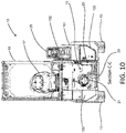
Figure 10 is a cross-sectional view of the vehicle ofFigure 1 on the plane C-C ofFigure 9 ; -
Figure 11 is a cross-sectional view of the vehicle on the plane D-D offigure 7 ; -
Figure 12 is an isometric view of the vehicle ofFigure 1 with the cab, bonnet and working arm removed; -
Figure 13 is detail E ofFigure 12 . - Referring to
Figures 1 to 4 of the drawings, a load handling vehicle of the telescopic lift truck type is indicated generally at 10. Thevehicle 10 has afront end 11 and arear end 12. Disposed on the front end region are a pair of a front groundengageable wheels 13 which are spaced apart width wise of the vehicle so as to be disposed one at eachside engageable wheels 16, again disposed width wise of the vehicle so that the wheels are disposed one at each side, 14, 15 of the vehicle. In this embodiment the vehicle has a wheelbase of 1.8m but in other embodiments vehicles of this type may have a wheelbase in a range of 1.5 - 2.0m. In addition, the overall length of the vehicle is 2911mm, but typically this could be expected to be in a range of 2m to 3.5m. - An
operator seat 17 is disposed in an operator'scompartment 18 in which is disposed asteering wheel 19 and the conventional foot and hand controls of the vehicle. - The operator's
compartment 18 is provided with a top 18a having a plurality ofopenings 18b which may be glazed as desired. Of course the pattern of openings and whether or not they are glazed can be modified as necessary. The operator'scompartment 18 is provided so as to be of adequate strength to satisfy the necessary safety requirements in a conventional manner. - With reference to
Figs 9 to 12 , disposed beneath the operator'sseat 17 is aspace 19 accommodating anelectric motor 20 connected to apump 21 which provides fluid via suitable conduits to hydraulic actuators arranged to move the working arm as discussed in more detail below. First and secondelectric drive motors Fig. 12 ) directly drivingly connect to thefront wheels 13 which are mounted on the vehicle in conventional manner and which are not steerable. - The
rear wheels 16 are mounted by conventional steered axle 16a and are undriven but are steerable by means of steering actuator (not visible). - The front and rear wheels together with the
motors - The vehicle is provided with a single
telescopic boom 25 which extends in a forward direction of the truck parallel to, and off-set width-wise from, a central plane X-X of the vehicle. Theboom 25 is mounted on the structure for up and down swinging movement by apivot point 26 disposed in arear end region 27 of the boom and also disposed in arear end region 28 of the vehicle. The overall boom length when retracted is approximately 83% of the total machine length, but in other embodiments may be between 75% and 100%. - The
boom 25 is offset from the central plane X-X so as generally to overlie the front andrear wheels side 14 of the vehicle and to provide a space for the operator'scompartment 18 between theboom 25 and theopposite side 15 of the vehicle. - The
boom 25 comprises arearward portion 29a and aforward portion 29b telescopically received within therearward portion 29a in conventional manner. An extension ram (not visible) is provided between theboom parts boom part 29b. - The
forward boom part 29a is provided with a width wise extendingportion 31 which extends from theboom part 29a towards theopposite side 15 of the vehicle and which carries an implementcarriage 32. The implementcarriage 32 may be provided with any desired load handling implement such as a pair of forks or a platform or any other desired load handling implement. - The implement
carriage 32 is connected to the transversely extendingpart 31 by a pair of pivot points 33 for pivotable crowd movement about a generally horizontal axis. The pivot points 33 are each carried on a limb 34 which extends downwardly from the transversely extendingmember 31. - The implement
carriage 32 is connected to the limbs 34 for pivotal movement under the control of a crowd actuator comprising a pair of crowd rams 35. - The
boom 25 is caused to swing up and down by alift ram 40 connected in a known manner. - The
operator compartment 18 may be arranged to pivot forwardly relative to the remainder of the structure about an axis provided by apivot 38 so that the operator compartment may be tilted upwardly and forwardly along with the seat, steering column and controls in conventional manner to provide access to theelectric motor 20, pump 21, and other components within thespace 19. - The
operator compartment 18 may be glazed on one or more sides. If glazed on all sides it is provided with an access door, not shown. - Referring now to
figures 10 to 12 the vehicle has achassis 100 made as a welded fabrication of plate metal forming the structure of the vehicle that is required to transmit and react the offset load from theboom 25. This structure differs significantly from conventional mast type forklifts where the majority of the load is transmitted directly from the mast to the front wheels. - The
chassis 100 comprises a pair of generally planarside frame members side frame member 103 disposed on the opposite side of the vehicle. Theframe members rear portions rear wheels side frame members part aperture 101b, for thepivot point 26. The frame members may be manufactured from steel plate that is around 15mm thick. - The front
transverse member 104 is provided with a pair ofupstanding brackets 109 for pivotably mounting theoperator compartment 18 via thepivot 38. - In addition, the chassis at the front end, is provided with a pair of forwardly projecting
parts 106 to mount theelectric drive motors - In the present example the ratio of the width of the operator's compartment to the overall width of the vehicle is 0.67:1 and the above mentioned ratio may lie, if desired, in the range 0.5:1 to 0.8:1.
- In the present example the vehicle has an overall width of 1270mm. If desired, the width may be other than that specifically described with reference to the example and is generally less than 1.3m.
- The
boom 25 is disposed so that when the boom is in a lowered position, as illustrated, an operator may see laterally as well as forwardly and rearwardly over the top of the boom and the load carrying implement. Even when the boom is being raised or lowered the operator view is relatively unobstructed as the operator's vision is only obstructed when the implement and any load carrier thereon is in his line of sight. This is in contrast with a conventional fork lift truck in that the operator's view forwardly is not obstructed by any permanently present mast. - With reference in particular to
Figures 4 to 12 , the incorporation of abattery pack 50 into the load-handlingvehicle 10 is described in more detail. - In this embodiment the battery pack comprises a plurality of individual cells 52 which are generally cuboid in shape. The cells 52 in this embodiment are lead acid cells and each cell has a voltage of 2 volts and capacity of 1.2 kWh. The
battery pack 50 comprises in thisembodiment 40 such cells 52 which thereby provides a total battery capacity of 50 kWh and 625 Ah. For a vehicle of the type described above undertaking a standard duty cycle, and with a suitable safety margin provided, it is considered that the capacity is sufficient to power thevehicle 10 for an 8 hour shift. - In this embodiment, lead acid batteries are utilised as they are widely accepted in the forklift truck industry. Further, due to their density, are additionally useful to counter balance the load to be carried by the
vehicle 10 if suitably positioned thereon. However, in other embodiments alternative battery technology may be used, such as lithium ion, or the batteries may be partially or wholly replaced in the battery pack by other electrical storage media such as super capacitors. - As can be seen most clearly in
Figure 5A , thebattery pack 50 comprises acontainer 54 having a base and vertical walls fabricated, for example, from sheet steel in which the cells 52 are housed. The underside of thecontainer 54 is provided with threeelongate support legs 56 which between them define two channels that enable a standard fork attachment of a load handling vehicle to be inserted under thecontainer 54 and for thebattery pack 50 to therefore be lifted and moved by a load-handlingvehicle 10 of the present invention, or indeed by a conventional forklift truck or other working machine. - Further, the
container 54 is provided proximate the upper edge of two opposing side walls with liftingeyes 58 per side. Theeyes 58 are located in such a position as to permit an arrangement of ropes or chains to be attached thereto and to lift thebattery pack 50 at its centre of gravity. Further, or alternatively, a liftingeye 58 is provided in thebattery pack 50 at or around the actual centre of gravity of the battery pack so that it may be lifted by a single chain or rope that is clear of a bonnet when lifted (discussed in further detail below) of thevehicle 10. This lifting eye may be formed in a divider sheet arranged to separate adjacent rows of cells 52 within the container. It will be appreciated that thecontainer 54 provides the structural strength to enable thebattery pack 50 to be lifted, as well as also providing a measure of protection for the cells 52 within it from external impacts, e.g., during handling. - As can be seen in
Figures 5 and 5A in particular, contrary to known battery packs, thebattery pack 50 of the present invention is of a non-regular shape. That is to say that despite being filled with individual cells that are of a uniform cuboid shape, thebattery pack 50 is not itself square or rectangular in plan view, i.e., it is non-symmetrical about either a front-to-rear axis or side-to-side axis. Specifically, in this embodiment thebattery pack 50 has a dog leg configuration in which two cells 52 define aprotrusion 60 from one side of what would otherwise be a generally rectangular shape of pack. Further, on the opposite side to theprotrusion 60, one corner of thepack 62 is recessed as indicated at 62. As is visible inFigures 5 and 5A , this irregular shape is achieved by packing the cells 52 within thecontainer 54 without any substantial voids or wasted space being present therein. As can also be seen inFigure 5A , thecontainer 54 is chamfered in the region of theprotrusion 60 andrecess 62 such that the wall of the container interconnecting these two features is lower than the other three walls. for illustrative purposes, in this embodiment, the battery pack has an overall width (including protrusion 60) of 912mm, a length of 1124mm, and height of 667mm. - Finally, the
battery pack 50 is also provided with aconnector 64 on the top thereof to couple the battery pack to anelectrical supply 66 of thevehicle 10 as can be seen inFigures 7 and9 for example (or to a charger to recharge the battery pack - not shown). - As can be seen in
Figures 7, 8 and11 aplatform 42 is provided generally towards the rear of thevehicle 10 to receive thebattery pack 50. For reasons of stability and rearward operator visibility, it is desirable for theplatform 42 to be as low as possible. As such the height of the platform is defined by the uppermost surface of the transverse rear frame member 105 (which is itself limited by the height of the wheels and steering mechanism), as well as the uppermost surface of acounter weight 44 mounted rearwardly of therear wheels 16. In this embodiment, the height of the platform is 573mm, but in other embodiments may be in a range of 0.65m to 0.500m. In this embodiment the rear overhang (distance from rotational axis ofrear wheels 16 to rear of vehicle) is 634mm but may be in a range of 0.2m to 0.8m. - Forward of the transverse rear frame member, an additional support plate is provided so that a horizontal surface is provided along the entirety of the battery pack and this terminates in a
bulkhead 46 that acts as a forward stop for thebattery pack 50, as well as being a mounting location for the operator'scompartment 18. To guide and support thebattery pack 50 laterally, at the boom side thereof, the second planarside frame member 102 may act as a guide and on the opposing side, afurther upright support 48 is also provided, that acts as a guide, as well as supporting the bodywork of the vehicle. - At the rear, a
battery access door 30 pivotable about a vertical axis is provided and finally, a bonnet orhood 27 mounted to pivot about a front horizontal axis above the battery pack. As such, theplatform 42,bulkhead 46, second planarside frame member 102,upright support 48,access door 30 andbonnet 27 define anenclosed battery compartment 49 of thevehicle 10. - With reference to the
battery access door 30, it is important to recognise that this represents an important safety feature of thevehicle 10. Specifically, the rear wheel steer arrangement of the vehicle and the fact that it operates in confined spaces, means that the rear 12 of the machine is particularly susceptible to accidental collisions and impacts with foreign bodies. As leakage of acid from lead acid batteries by virtue of them being punctured by such an impact would result in a significant safety risk, it is therefore important that thebattery access door 30 is not merely cosmetic in nature and in fact has sufficient strength to withstand accidental impact that may occur in use and prevent the intrusion of foreign bodies into thebattery pack 50. Therefore, the battery access door is manufactured of heavy gauge steel (e.g. greater than 10mm thick) or a casting of e.g. spheroidal graphite iron, is pivotably mounted to the first planar side frame member 101 (Fig. 12 ) via ahinge 28 and is further reinforced with reinforcing members orribs 30a as can be seen inFigure 9 . Further, the forming of the door into three mutually angled vertical faces adds to the inherent structural integrity whilst reducing the degree to which the rear of the vehicle swings outwards during cornering manoeuvres thereby reducing the risk of impact in the first place. It will be noted that the provision of therecess 62 in thebattery pack 50 is to allow the battery pack to fit within the angled shape. - Due to the
battery access door 30 being strong, it additionally has a significant mass (of the order of 200kg or more) and therefore provides an additional counterweight. It is therefore important that before the vehicle is operated, the door is securely closed, firstly so that it cannot swing freely and hit foreign objects, and secondly so that it can be assured that it is in place to protect thebattery pack 50. To this end, thevehicle 10 is fitted with a sensor that acts as an interlock in the electrical control system such that it is not possible for the machine to be operated until it has sensed that thebattery access door 30 is properly closed and latched. For example a non-contact vane or Hall Effect sensor (not visible) may be mounted on thehinge 28 to act as the interlock. Additionally, therelease mechanism 37 for the latch is recessed within theupright support 48 and only accessible once thebonnet 27 is lifted thereby preventing inadvertent opening of thebattery access door 30 and protecting the latch from damage. In other embodiments the sensor may be connected to an audible and/or visual warning signal rather that or in addition to an interlock - Referring now to
Figures 10 to 13 thespace 19 under the operator compartment can be seen in more detail. Thisspace 19 conveniently houses electronic control systems indicated generally at 23, thehydraulic pump 21 for hydraulic systems such as the varioushydraulic rams motor 20. The space is well protected, but nevertheless easily accessible by tilting theoperator compartment 18 forward. - The control systems include a
controller 23a for thehydraulic pump motor 20, andindividual controllers 23b for thedrive motors - It can be seen that the
controllers side frame member 102 via a plate. The plate is a heat sink plate 68, manufactured from a heat conductive material such as aluminium. A box section region 107 is defined between the first and secondside frame members - The control electronics generate a significant amount of heat in operation, and the particular mounting arrangement utilises the
chassis 100 as an effective heat sink. The plate 68 assists in the transmission of heat away from the electronics and into the chassis. This arrangement contrasts with known systems on conventional electric mast type forklift trucks that typically require forced air cooling for the control electronics that may add to complexity, cost and parasitic losses of electrical power. -
Figures 5 ,6 and7 show thebattery pack 50 in situ on theplatform 42. FromFigures 5 and6 in particular it can be seen that theprotrusion 60 of the battery pack extends rearwardly of the boom over approximately half the width thereof in a lateral or sideways direction. As such, theprotrusion 60 maximises the utilisation of available space within thevehicle 10 whilst continuing to use cells of a standard size. Furthermore, by having abattery pack 50 of an irregular shape it becomes impossible to fit the pack onto theplatform 42 in an incorrect orientation because it simply would not fit. As such, this ensures that theconnector 64 to theelectrical supply 66 is correctly positioned for connection. In other words, the shape of the battery pack functions as a fool-proofing or "poka yoke" feature. - By utilising the maximum available area of the
vehicle 10 to receive thebattery pack 50, the height of the battery pack can be minimised. Therefore the combination of this with the relatively low height of the platform means that the top of the bonnet is also low, in this embodiment 1423mm, but is typically in the range of 1.5 to 1m. This means that an operator has good rear visibility to lessen the risk of unwanted collisions with foreign objects. The chamfer at the rear of thecontainer 54 further enables the bonnet to slope downwardly in a rearward direction, further improving the rear visibility. The enables thevehicle 10 to comply with the ISO13564-1 ("Powered industrial trucks -- Test methods for verification of visibility -- Part 1: Sit-on and stand-on operator trucks and variable-reach trucks up to and including 10 t capacity") standard for visibility without the need for additional aids such as mirrors or cameras. - In order to remove the
battery pack 50 for charging, firstly thebonnet 27 is lifted and theelectrical supply 66 disconnected fromconnector 64. From the same position the operator can then actuate therelease mechanism 37 for thebattery access door 30 and open the door. In locations where a second load-handling vehicle is available, this will then be used to insert forks underneath thebattery pack 50, lift it and reverse it out of thebattery compartment 49 otherwise a crane or lifting device with chains or rope connected to the liftingeyes 58 may be used. The battery pack can then be charged away from thevehicle 10. A second fully charged battery pack can then be loaded onto theplatform 42 by the second load-handling vehicle, theelectrical supply 66 connected toconnector 64, therear door 30 closed and latched and the bonnet lowered and latched for further operation of the vehicle. As noted previously the interlock on thebattery access door 30 prevents operation of thevehicle 10 until it is sensed that the rear door is latched. - It will be appreciated that numerous changes may be made within the scope of the present invention. For example, whilst various dimensions and proportions of the vehicle have been discussed above, these may be adjusted as required depending on the particular application, e.g., if a lower powered more compact version of the machine is desired the dimensions may be reduced, as a larger version of the machine may be longer and/or wider. The battery access door may be curved rather than faceted, or may have more or fewer than three faces. It may be pivotally mounted about a horizontal axis and/or may be combined with the bonnet into a single moveable battery access door.
- Further, although not currently preferred, it may nevertheless be possible for the loading and removal of the battery to occur in a sideways direction towards and away from the boom 29. In this case, the battery access door at 30 at the rear may be replaced by a solid immovable structure and a separate battery access door be located at the side in place of the
upright support 48.
Claims (15)
- A load-handling vehicle, comprising:a body;a boom, pivotally mounted to the body at a rear end region so that the boom can pivot up and down about an axis extending laterally with respect to the vehicle, wherein the boom has a load carrying implement attachable at a forward end region thereof;a steerable ground engageable propulsion arrangement;an electrically powered drive for the propulsion arrangement;a platform positioned at the rear of the body and to the side of the boom;a battery pack positioned on the platform.
- A load-handling vehicle according to claim 1 wherein the battery pack has a non-regular shape in plan view, preferably wherein the battery pack comprises a recess in plan view at a rear corner thereof on an opposite side of the vehicle to the boom, more preferably wherein the battery pack comprises a plurality of standard sized cells arranged to achieve the non-regular shape.
- A load-handling vehicle according to claim 1 wherein the battery pack comprises lateral projection configured to locate rearwardly of the boom.
- A load-handling vehicle according to any preceding claim wherein the platform is configured to permit the removal of the battery pack in a rearward direction and loading in a forward direction.
- A load-handling vehicle according to claim 4 wherein a battery access door is located rearward of the battery pack and is operable so as to permit access thereto, preferably wherein the battery access door is structurally reinforced, more preferably wherein the vehicle further comprises a sensor associated with the battery access door contained to sense if the door is open or closed, even more preferably wherein the vehicle further comprises an interlock to prevent operation of the vehicle if the battery access door is not closed.
- A load-handling vehicle according to claim 5 wherein the battery access door is hingedly mounted to a structural part of the body of the vehicle, preferably the battery access door is mounted to a chassis portion of the body that pivotably mounts the boom.
- A load-handling vehicle according to any preceding claim wherein the ground engagable propulsion arrangement comprises a pair of wheels arranged towards the front of the vehicle and a pair of wheels arranged towards the rear of the vehicle, preferably wherein the rear wheels of the propulsion arrangement are steered.
- A load-handling vehicle according to any preceding claim wherein the vehicle further comprises an operator compartment arranged generally forward of the battery pack.
- A load-handling vehicle according to claim 8 wherein a portion of the operator compartment is arranged above the battery pack.
- A load-handling vehicle according to any one of claims 7 to 9 wherein a space is provided within the volume intermediate the front and rear wheels and offset to the side of the boom to accommodate functional components of the vehicle.
- A load-handling vehicle according to claim 10 wherein the operator compartment is located above the space, preferably wherein the operator compartment is moveable with respect to the body.
- A load-handling vehicle according to claim 10 or to claim 11 wherein the vehicle comprises a control system and the control system is located in the space, preferably wherein the control system is a battery management system; a propulsion control system; a vehicle ECU or a controller for operation of the boom.
- A load-handling vehicle according to claim 12 wherein the vehicle further comprises a structural member of the body and the control system is mounted to the structural member, preferably wherein a heat sink is mounted intermediate the control system and the structural member.
- A load-handling vehicle according to any preceding claim further comprising an electric motor drivingly connected to a hydraulic pump arranged to supply hydraulic fluid to actuate movement of the boom.
- A load-handling vehicle according to claim 14 when dependent upon any one of claims 10 to 13 wherein the electric motor and hydraulic pump are located within the space.
Applications Claiming Priority (1)
| Application Number | Priority Date | Filing Date | Title |
|---|---|---|---|
| GB1804890.0A GB2572356B (en) | 2018-03-27 | 2018-03-27 | Load-handling vehicle |
Publications (2)
| Publication Number | Publication Date |
|---|---|
| EP3546418A1 true EP3546418A1 (en) | 2019-10-02 |
| EP3546418B1 EP3546418B1 (en) | 2022-04-27 |
Family
ID=62067956
Family Applications (1)
| Application Number | Title | Priority Date | Filing Date |
|---|---|---|---|
| EP19165048.0A Active EP3546418B1 (en) | 2018-03-27 | 2019-03-25 | Load-handling vehicle |
Country Status (4)
| Country | Link |
|---|---|
| US (1) | US10829351B2 (en) |
| EP (1) | EP3546418B1 (en) |
| ES (1) | ES2914339T3 (en) |
| GB (1) | GB2572356B (en) |
Cited By (5)
| Publication number | Priority date | Publication date | Assignee | Title |
|---|---|---|---|---|
| EP4019456A1 (en) * | 2020-12-28 | 2022-06-29 | Manitou Italia S.r.l. | Electric telehandler |
| WO2023001621A1 (en) * | 2021-07-20 | 2023-01-26 | Manitou Bf | On-site vehicle comprising battery elements |
| FR3125521A1 (en) * | 2021-07-20 | 2023-01-27 | Manitou Bf | Work machine comprising battery elements |
| EP4306724A1 (en) | 2022-07-15 | 2024-01-17 | Yanmar Holdings Co., Ltd. | Electric work machine |
| RU2854802C2 (en) * | 2020-12-28 | 2026-01-19 | МАНИТОУ ИТАЛИА С.р.л. | Improved electric telescopic loader |
Families Citing this family (12)
| Publication number | Priority date | Publication date | Assignee | Title |
|---|---|---|---|---|
| KR20250041618A (en) | 2017-07-13 | 2025-03-25 | 에티움, 엘엘씨 | Modular lithium-ion battery system for fork lifts |
| WO2019195052A1 (en) * | 2018-04-03 | 2019-10-10 | Walmart Apollo, Llc | Contingency battery charging system |
| US11427450B2 (en) | 2018-06-01 | 2022-08-30 | Hyster-Yale Group, Inc. | Lift truck having advantageous design elements |
| WO2021178200A1 (en) | 2020-03-06 | 2021-09-10 | Manitou Equipment America, Llc | Electric motor driven loader with electric motor powered hydraulics |
| US12590440B2 (en) | 2021-06-28 | 2026-03-31 | Doosan Bobcat North America, Inc. | Systems and methods for control of excavators and other power machines |
| CN117500986A (en) | 2021-06-28 | 2024-02-02 | 斗山山猫北美公司 | Systems and methods for controlling excavators and other powered machines |
| US12110087B1 (en) * | 2021-06-30 | 2024-10-08 | Brp Marine Us Inc. | Method and system for replacing a watercraft battery |
| CA3236274A1 (en) * | 2021-10-26 | 2023-05-04 | Kennon Guglielmo | Forklift kit with interchangeable power system conversion units |
| FR3137874B1 (en) * | 2022-07-18 | 2024-05-31 | Manitou Bf | Work machine with a cabin located laterally and a battery module fixed under the cabin |
| IT202400004900A1 (en) * | 2024-03-06 | 2025-09-06 | Toyota Mat Handling Manufacturing Italy S P A | FORKLIFT |
| FR3164993A1 (en) * | 2024-07-23 | 2026-01-30 | Manitou Bf | Handling machine |
| EP4686694A1 (en) * | 2024-07-30 | 2026-02-04 | TOYOTA MATERIAL HANDLING MANUFACTURING ITALY S.p.A | Industrial truck including improved cable restraint element |
Citations (3)
| Publication number | Priority date | Publication date | Assignee | Title |
|---|---|---|---|---|
| FR3018797A1 (en) * | 2014-03-19 | 2015-09-25 | Geismar Ancien Ets L | WEIGHT LIFTING MACHINE, INCLUDING A CRANE ARRANGEMENT DEVICE AND A COUNTERWEIGHT DEVICE |
| CN104500113B (en) * | 2014-12-06 | 2016-08-24 | 中国煤炭科工集团太原研究院有限公司 | Accumulator column dismounting vehicle |
| US20170362796A1 (en) * | 2016-06-21 | 2017-12-21 | Kubota Corporation | Work machine |
Family Cites Families (7)
| Publication number | Priority date | Publication date | Assignee | Title |
|---|---|---|---|---|
| US3047172A (en) * | 1959-07-22 | 1962-07-31 | Yale & Towne Mfg Co | Lift truck |
| FR2690895A1 (en) * | 1992-05-07 | 1993-11-12 | Manitou Bf | Electric forklift with telescopic arm. |
| EP0701963B2 (en) * | 1994-09-14 | 2004-08-18 | Manitou Bf | Motorised lift truck with telescopic arm |
| KR101815331B1 (en) * | 2010-06-15 | 2018-01-04 | 가부시키가이샤 히다치 겡키 티에라 | Electric construction machine |
| US9566954B2 (en) * | 2014-03-10 | 2017-02-14 | Max Moskowitz | Vehicular accessory |
| US9458601B2 (en) * | 2014-11-20 | 2016-10-04 | Duane G. Shipman | Apparatus for mounting a tool to a power vehicle |
| CN107337155A (en) * | 2017-07-13 | 2017-11-10 | 河南麻省新能石化实业有限公司 | Micro-type automated fork truck and application process |
-
2018
- 2018-03-27 GB GB1804890.0A patent/GB2572356B/en active Active
-
2019
- 2019-03-25 EP EP19165048.0A patent/EP3546418B1/en active Active
- 2019-03-25 ES ES19165048T patent/ES2914339T3/en active Active
- 2019-03-27 US US16/367,117 patent/US10829351B2/en active Active
Patent Citations (3)
| Publication number | Priority date | Publication date | Assignee | Title |
|---|---|---|---|---|
| FR3018797A1 (en) * | 2014-03-19 | 2015-09-25 | Geismar Ancien Ets L | WEIGHT LIFTING MACHINE, INCLUDING A CRANE ARRANGEMENT DEVICE AND A COUNTERWEIGHT DEVICE |
| CN104500113B (en) * | 2014-12-06 | 2016-08-24 | 中国煤炭科工集团太原研究院有限公司 | Accumulator column dismounting vehicle |
| US20170362796A1 (en) * | 2016-06-21 | 2017-12-21 | Kubota Corporation | Work machine |
Cited By (6)
| Publication number | Priority date | Publication date | Assignee | Title |
|---|---|---|---|---|
| EP4019456A1 (en) * | 2020-12-28 | 2022-06-29 | Manitou Italia S.r.l. | Electric telehandler |
| US11993496B2 (en) | 2020-12-28 | 2024-05-28 | Manitou Italia S.R.L. | Electric telehandler |
| RU2854802C2 (en) * | 2020-12-28 | 2026-01-19 | МАНИТОУ ИТАЛИА С.р.л. | Improved electric telescopic loader |
| WO2023001621A1 (en) * | 2021-07-20 | 2023-01-26 | Manitou Bf | On-site vehicle comprising battery elements |
| FR3125521A1 (en) * | 2021-07-20 | 2023-01-27 | Manitou Bf | Work machine comprising battery elements |
| EP4306724A1 (en) | 2022-07-15 | 2024-01-17 | Yanmar Holdings Co., Ltd. | Electric work machine |
Also Published As
| Publication number | Publication date |
|---|---|
| GB2572356B (en) | 2022-09-14 |
| GB201804890D0 (en) | 2018-05-09 |
| ES2914339T3 (en) | 2022-06-09 |
| US20190300348A1 (en) | 2019-10-03 |
| EP3546418B1 (en) | 2022-04-27 |
| GB2572356A (en) | 2019-10-02 |
| US10829351B2 (en) | 2020-11-10 |
Similar Documents
| Publication | Publication Date | Title |
|---|---|---|
| EP3546418B1 (en) | Load-handling vehicle | |
| KR100306942B1 (en) | Battery-powered industrial vehicle | |
| US11499291B2 (en) | Work machine | |
| EP2983971B1 (en) | Electric dumper vehicle | |
| CA3236274A1 (en) | Forklift kit with interchangeable power system conversion units | |
| US12215011B2 (en) | Autonomously guided industrial truck having a pair of scanner units | |
| US6736587B2 (en) | Battery-electrically operated industrial truck, particularly counterweighted fork-lift truck | |
| GB2387366A (en) | Industrial truck having cast frame | |
| CN207809549U (en) | A kind of fork truck | |
| CN206232376U (en) | It is a kind of to lift door frame and apply its balance weight type forklift | |
| EP4067289B1 (en) | Industrial truck with improved structure for supporting the battery | |
| CN216129284U (en) | Rollover prevention device of small electric forklift | |
| US20250065770A1 (en) | Mobile equipment optimized to support swappable battery machinery | |
| US12264054B2 (en) | Base plate for an autonomously guided industrial truck | |
| EP4613938A2 (en) | A material handling machine | |
| US20260042648A1 (en) | Autonomously-guided industrial truck having three structural levels | |
| RU211238U1 (en) | FORKLIFT | |
| CN212222331U (en) | AGV fork truck | |
| EP4556637A1 (en) | A material handling machine | |
| BR102016001938A2 (en) | truck-mounted forklift | |
| EP4467429A1 (en) | Trailer | |
| CN220078513U (en) | Rear hinged cross-country forklift | |
| US20250129568A1 (en) | Material Handling Machine | |
| CN213707633U (en) | Shock attenuation fork truck with protector | |
| GB2639047A (en) | A material handling machine |
Legal Events
| Date | Code | Title | Description |
|---|---|---|---|
| PUAI | Public reference made under article 153(3) epc to a published international application that has entered the european phase |
Free format text: ORIGINAL CODE: 0009012 |
|
| STAA | Information on the status of an ep patent application or granted ep patent |
Free format text: STATUS: THE APPLICATION HAS BEEN PUBLISHED |
|
| AK | Designated contracting states |
Kind code of ref document: A1 Designated state(s): AL AT BE BG CH CY CZ DE DK EE ES FI FR GB GR HR HU IE IS IT LI LT LU LV MC MK MT NL NO PL PT RO RS SE SI SK SM TR |
|
| AX | Request for extension of the european patent |
Extension state: BA ME |
|
| STAA | Information on the status of an ep patent application or granted ep patent |
Free format text: STATUS: REQUEST FOR EXAMINATION WAS MADE |
|
| 17P | Request for examination filed |
Effective date: 20200402 |
|
| RBV | Designated contracting states (corrected) |
Designated state(s): AL AT BE BG CH CY CZ DE DK EE ES FI FR GB GR HR HU IE IS IT LI LT LU LV MC MK MT NL NO PL PT RO RS SE SI SK SM TR |
|
| GRAP | Despatch of communication of intention to grant a patent |
Free format text: ORIGINAL CODE: EPIDOSNIGR1 |
|
| STAA | Information on the status of an ep patent application or granted ep patent |
Free format text: STATUS: GRANT OF PATENT IS INTENDED |
|
| INTG | Intention to grant announced |
Effective date: 20211213 |
|
| GRAS | Grant fee paid |
Free format text: ORIGINAL CODE: EPIDOSNIGR3 |
|
| GRAA | (expected) grant |
Free format text: ORIGINAL CODE: 0009210 |
|
| STAA | Information on the status of an ep patent application or granted ep patent |
Free format text: STATUS: THE PATENT HAS BEEN GRANTED |
|
| AK | Designated contracting states |
Kind code of ref document: B1 Designated state(s): AL AT BE BG CH CY CZ DE DK EE ES FI FR GB GR HR HU IE IS IT LI LT LU LV MC MK MT NL NO PL PT RO RS SE SI SK SM TR |
|
| REG | Reference to a national code |
Ref country code: GB Ref legal event code: FG4D |
|
| REG | Reference to a national code |
Ref country code: CH Ref legal event code: EP |
|
| REG | Reference to a national code |
Ref country code: AT Ref legal event code: REF Ref document number: 1486824 Country of ref document: AT Kind code of ref document: T Effective date: 20220515 |
|
| REG | Reference to a national code |
Ref country code: DE Ref legal event code: R096 Ref document number: 602019014027 Country of ref document: DE |
|
| REG | Reference to a national code |
Ref country code: IE Ref legal event code: FG4D |
|
| REG | Reference to a national code |
Ref country code: ES Ref legal event code: FG2A Ref document number: 2914339 Country of ref document: ES Kind code of ref document: T3 Effective date: 20220609 |
|
| REG | Reference to a national code |
Ref country code: LT Ref legal event code: MG9D |
|
| REG | Reference to a national code |
Ref country code: NL Ref legal event code: MP Effective date: 20220427 |
|
| PG25 | Lapsed in a contracting state [announced via postgrant information from national office to epo] |
Ref country code: NL Free format text: LAPSE BECAUSE OF FAILURE TO SUBMIT A TRANSLATION OF THE DESCRIPTION OR TO PAY THE FEE WITHIN THE PRESCRIBED TIME-LIMIT Effective date: 20220427 |
|
| PG25 | Lapsed in a contracting state [announced via postgrant information from national office to epo] |
Ref country code: SE Free format text: LAPSE BECAUSE OF FAILURE TO SUBMIT A TRANSLATION OF THE DESCRIPTION OR TO PAY THE FEE WITHIN THE PRESCRIBED TIME-LIMIT Effective date: 20220427 Ref country code: PT Free format text: LAPSE BECAUSE OF FAILURE TO SUBMIT A TRANSLATION OF THE DESCRIPTION OR TO PAY THE FEE WITHIN THE PRESCRIBED TIME-LIMIT Effective date: 20220829 Ref country code: NO Free format text: LAPSE BECAUSE OF FAILURE TO SUBMIT A TRANSLATION OF THE DESCRIPTION OR TO PAY THE FEE WITHIN THE PRESCRIBED TIME-LIMIT Effective date: 20220727 Ref country code: LT Free format text: LAPSE BECAUSE OF FAILURE TO SUBMIT A TRANSLATION OF THE DESCRIPTION OR TO PAY THE FEE WITHIN THE PRESCRIBED TIME-LIMIT Effective date: 20220427 Ref country code: HR Free format text: LAPSE BECAUSE OF FAILURE TO SUBMIT A TRANSLATION OF THE DESCRIPTION OR TO PAY THE FEE WITHIN THE PRESCRIBED TIME-LIMIT Effective date: 20220427 Ref country code: GR Free format text: LAPSE BECAUSE OF FAILURE TO SUBMIT A TRANSLATION OF THE DESCRIPTION OR TO PAY THE FEE WITHIN THE PRESCRIBED TIME-LIMIT Effective date: 20220728 Ref country code: FI Free format text: LAPSE BECAUSE OF FAILURE TO SUBMIT A TRANSLATION OF THE DESCRIPTION OR TO PAY THE FEE WITHIN THE PRESCRIBED TIME-LIMIT Effective date: 20220427 Ref country code: BG Free format text: LAPSE BECAUSE OF FAILURE TO SUBMIT A TRANSLATION OF THE DESCRIPTION OR TO PAY THE FEE WITHIN THE PRESCRIBED TIME-LIMIT Effective date: 20220727 |
|
| PG25 | Lapsed in a contracting state [announced via postgrant information from national office to epo] |
Ref country code: RS Free format text: LAPSE BECAUSE OF FAILURE TO SUBMIT A TRANSLATION OF THE DESCRIPTION OR TO PAY THE FEE WITHIN THE PRESCRIBED TIME-LIMIT Effective date: 20220427 Ref country code: PL Free format text: LAPSE BECAUSE OF FAILURE TO SUBMIT A TRANSLATION OF THE DESCRIPTION OR TO PAY THE FEE WITHIN THE PRESCRIBED TIME-LIMIT Effective date: 20220427 Ref country code: LV Free format text: LAPSE BECAUSE OF FAILURE TO SUBMIT A TRANSLATION OF THE DESCRIPTION OR TO PAY THE FEE WITHIN THE PRESCRIBED TIME-LIMIT Effective date: 20220427 Ref country code: IS Free format text: LAPSE BECAUSE OF FAILURE TO SUBMIT A TRANSLATION OF THE DESCRIPTION OR TO PAY THE FEE WITHIN THE PRESCRIBED TIME-LIMIT Effective date: 20220827 |
|
| REG | Reference to a national code |
Ref country code: DE Ref legal event code: R097 Ref document number: 602019014027 Country of ref document: DE |
|
| PG25 | Lapsed in a contracting state [announced via postgrant information from national office to epo] |
Ref country code: SM Free format text: LAPSE BECAUSE OF FAILURE TO SUBMIT A TRANSLATION OF THE DESCRIPTION OR TO PAY THE FEE WITHIN THE PRESCRIBED TIME-LIMIT Effective date: 20220427 Ref country code: SK Free format text: LAPSE BECAUSE OF FAILURE TO SUBMIT A TRANSLATION OF THE DESCRIPTION OR TO PAY THE FEE WITHIN THE PRESCRIBED TIME-LIMIT Effective date: 20220427 Ref country code: RO Free format text: LAPSE BECAUSE OF FAILURE TO SUBMIT A TRANSLATION OF THE DESCRIPTION OR TO PAY THE FEE WITHIN THE PRESCRIBED TIME-LIMIT Effective date: 20220427 Ref country code: EE Free format text: LAPSE BECAUSE OF FAILURE TO SUBMIT A TRANSLATION OF THE DESCRIPTION OR TO PAY THE FEE WITHIN THE PRESCRIBED TIME-LIMIT Effective date: 20220427 Ref country code: DK Free format text: LAPSE BECAUSE OF FAILURE TO SUBMIT A TRANSLATION OF THE DESCRIPTION OR TO PAY THE FEE WITHIN THE PRESCRIBED TIME-LIMIT Effective date: 20220427 Ref country code: CZ Free format text: LAPSE BECAUSE OF FAILURE TO SUBMIT A TRANSLATION OF THE DESCRIPTION OR TO PAY THE FEE WITHIN THE PRESCRIBED TIME-LIMIT Effective date: 20220427 |
|
| PLBE | No opposition filed within time limit |
Free format text: ORIGINAL CODE: 0009261 |
|
| STAA | Information on the status of an ep patent application or granted ep patent |
Free format text: STATUS: NO OPPOSITION FILED WITHIN TIME LIMIT |
|
| PG25 | Lapsed in a contracting state [announced via postgrant information from national office to epo] |
Ref country code: AL Free format text: LAPSE BECAUSE OF FAILURE TO SUBMIT A TRANSLATION OF THE DESCRIPTION OR TO PAY THE FEE WITHIN THE PRESCRIBED TIME-LIMIT Effective date: 20220427 |
|
| 26N | No opposition filed |
Effective date: 20230130 |
|
| PG25 | Lapsed in a contracting state [announced via postgrant information from national office to epo] |
Ref country code: SI Free format text: LAPSE BECAUSE OF FAILURE TO SUBMIT A TRANSLATION OF THE DESCRIPTION OR TO PAY THE FEE WITHIN THE PRESCRIBED TIME-LIMIT Effective date: 20220427 |
|
| P01 | Opt-out of the competence of the unified patent court (upc) registered |
Effective date: 20230523 |
|
| PG25 | Lapsed in a contracting state [announced via postgrant information from national office to epo] |
Ref country code: MC Free format text: LAPSE BECAUSE OF FAILURE TO SUBMIT A TRANSLATION OF THE DESCRIPTION OR TO PAY THE FEE WITHIN THE PRESCRIBED TIME-LIMIT Effective date: 20220427 |
|
| REG | Reference to a national code |
Ref country code: CH Ref legal event code: PL |
|
| REG | Reference to a national code |
Ref country code: BE Ref legal event code: MM Effective date: 20230331 |
|
| PG25 | Lapsed in a contracting state [announced via postgrant information from national office to epo] |
Ref country code: LU Free format text: LAPSE BECAUSE OF NON-PAYMENT OF DUE FEES Effective date: 20230325 |
|
| REG | Reference to a national code |
Ref country code: IE Ref legal event code: MM4A |
|
| PG25 | Lapsed in a contracting state [announced via postgrant information from national office to epo] |
Ref country code: LI Free format text: LAPSE BECAUSE OF NON-PAYMENT OF DUE FEES Effective date: 20230331 Ref country code: IE Free format text: LAPSE BECAUSE OF NON-PAYMENT OF DUE FEES Effective date: 20230325 Ref country code: CH Free format text: LAPSE BECAUSE OF NON-PAYMENT OF DUE FEES Effective date: 20230331 |
|
| PG25 | Lapsed in a contracting state [announced via postgrant information from national office to epo] |
Ref country code: BE Free format text: LAPSE BECAUSE OF NON-PAYMENT OF DUE FEES Effective date: 20230331 |
|
| REG | Reference to a national code |
Ref country code: AT Ref legal event code: UEP Ref document number: 1486824 Country of ref document: AT Kind code of ref document: T Effective date: 20220427 |
|
| PG25 | Lapsed in a contracting state [announced via postgrant information from national office to epo] |
Ref country code: BG Free format text: LAPSE BECAUSE OF FAILURE TO SUBMIT A TRANSLATION OF THE DESCRIPTION OR TO PAY THE FEE WITHIN THE PRESCRIBED TIME-LIMIT Effective date: 20220427 |
|
| PG25 | Lapsed in a contracting state [announced via postgrant information from national office to epo] |
Ref country code: BG Free format text: LAPSE BECAUSE OF FAILURE TO SUBMIT A TRANSLATION OF THE DESCRIPTION OR TO PAY THE FEE WITHIN THE PRESCRIBED TIME-LIMIT Effective date: 20220427 |
|
| PGFP | Annual fee paid to national office [announced via postgrant information from national office to epo] |
Ref country code: ES Payment date: 20250429 Year of fee payment: 7 |
|
| PG25 | Lapsed in a contracting state [announced via postgrant information from national office to epo] |
Ref country code: CY Free format text: LAPSE BECAUSE OF FAILURE TO SUBMIT A TRANSLATION OF THE DESCRIPTION OR TO PAY THE FEE WITHIN THE PRESCRIBED TIME-LIMIT; INVALID AB INITIO Effective date: 20190325 |
|
| PG25 | Lapsed in a contracting state [announced via postgrant information from national office to epo] |
Ref country code: HU Free format text: LAPSE BECAUSE OF FAILURE TO SUBMIT A TRANSLATION OF THE DESCRIPTION OR TO PAY THE FEE WITHIN THE PRESCRIBED TIME-LIMIT; INVALID AB INITIO Effective date: 20190325 |
|
| PG25 | Lapsed in a contracting state [announced via postgrant information from national office to epo] |
Ref country code: TR Free format text: LAPSE BECAUSE OF FAILURE TO SUBMIT A TRANSLATION OF THE DESCRIPTION OR TO PAY THE FEE WITHIN THE PRESCRIBED TIME-LIMIT Effective date: 20220427 |
|
| PGFP | Annual fee paid to national office [announced via postgrant information from national office to epo] |
Ref country code: GB Payment date: 20260316 Year of fee payment: 8 |
|
| PGFP | Annual fee paid to national office [announced via postgrant information from national office to epo] |
Ref country code: DE Payment date: 20260319 Year of fee payment: 8 |
|
| PGFP | Annual fee paid to national office [announced via postgrant information from national office to epo] |
Ref country code: AT Payment date: 20260320 Year of fee payment: 8 |
|
| PGFP | Annual fee paid to national office [announced via postgrant information from national office to epo] |
Ref country code: IT Payment date: 20260319 Year of fee payment: 8 |
|
| PGFP | Annual fee paid to national office [announced via postgrant information from national office to epo] |
Ref country code: FR Payment date: 20260320 Year of fee payment: 8 |