EP3546394A1 - Support structure with improved fastening means for an articulated-link conveyor - Google Patents
Support structure with improved fastening means for an articulated-link conveyor Download PDFInfo
- Publication number
- EP3546394A1 EP3546394A1 EP19158798.9A EP19158798A EP3546394A1 EP 3546394 A1 EP3546394 A1 EP 3546394A1 EP 19158798 A EP19158798 A EP 19158798A EP 3546394 A1 EP3546394 A1 EP 3546394A1
- Authority
- EP
- European Patent Office
- Prior art keywords
- support
- guides
- guide structure
- guide
- articulated
- Prior art date
- Legal status (The legal status is an assumption and is not a legal conclusion. Google has not performed a legal analysis and makes no representation as to the accuracy of the status listed.)
- Granted
Links
Images



Classifications
-
- B—PERFORMING OPERATIONS; TRANSPORTING
- B65—CONVEYING; PACKING; STORING; HANDLING THIN OR FILAMENTARY MATERIAL
- B65G—TRANSPORT OR STORAGE DEVICES, e.g. CONVEYORS FOR LOADING OR TIPPING, SHOP CONVEYOR SYSTEMS OR PNEUMATIC TUBE CONVEYORS
- B65G21/00—Supporting or protective framework or housings for endless load-carriers or traction elements of belt or chain conveyors
- B65G21/20—Means incorporated in, or attached to, framework or housings for guiding load-carriers, traction elements or loads supported on moving surfaces
- B65G21/2009—Magnetic retaining means
-
- B—PERFORMING OPERATIONS; TRANSPORTING
- B65—CONVEYING; PACKING; STORING; HANDLING THIN OR FILAMENTARY MATERIAL
- B65G—TRANSPORT OR STORAGE DEVICES, e.g. CONVEYORS FOR LOADING OR TIPPING, SHOP CONVEYOR SYSTEMS OR PNEUMATIC TUBE CONVEYORS
- B65G15/00—Conveyors having endless load-conveying surfaces, i.e. belts and like continuous members, to which tractive effort is transmitted by means other than endless driving elements of similar configuration
- B65G15/60—Arrangements for supporting or guiding belts, e.g. by fluid jets
- B65G15/62—Guides for sliding belts
-
- B—PERFORMING OPERATIONS; TRANSPORTING
- B65—CONVEYING; PACKING; STORING; HANDLING THIN OR FILAMENTARY MATERIAL
- B65G—TRANSPORT OR STORAGE DEVICES, e.g. CONVEYORS FOR LOADING OR TIPPING, SHOP CONVEYOR SYSTEMS OR PNEUMATIC TUBE CONVEYORS
- B65G15/00—Conveyors having endless load-conveying surfaces, i.e. belts and like continuous members, to which tractive effort is transmitted by means other than endless driving elements of similar configuration
- B65G15/60—Arrangements for supporting or guiding belts, e.g. by fluid jets
- B65G15/64—Arrangements for supporting or guiding belts, e.g. by fluid jets for automatically maintaining the position of the belts
-
- B—PERFORMING OPERATIONS; TRANSPORTING
- B65—CONVEYING; PACKING; STORING; HANDLING THIN OR FILAMENTARY MATERIAL
- B65G—TRANSPORT OR STORAGE DEVICES, e.g. CONVEYORS FOR LOADING OR TIPPING, SHOP CONVEYOR SYSTEMS OR PNEUMATIC TUBE CONVEYORS
- B65G17/00—Conveyors having an endless traction element, e.g. a chain, transmitting movement to a continuous or substantially-continuous load-carrying surface or to a series of individual load-carriers; Endless-chain conveyors in which the chains form the load-carrying surface
- B65G17/06—Conveyors having an endless traction element, e.g. a chain, transmitting movement to a continuous or substantially-continuous load-carrying surface or to a series of individual load-carriers; Endless-chain conveyors in which the chains form the load-carrying surface having a load-carrying surface formed by a series of interconnected, e.g. longitudinal, links, plates, or platforms
- B65G17/08—Conveyors having an endless traction element, e.g. a chain, transmitting movement to a continuous or substantially-continuous load-carrying surface or to a series of individual load-carriers; Endless-chain conveyors in which the chains form the load-carrying surface having a load-carrying surface formed by a series of interconnected, e.g. longitudinal, links, plates, or platforms the surface being formed by the traction element
-
- B—PERFORMING OPERATIONS; TRANSPORTING
- B65—CONVEYING; PACKING; STORING; HANDLING THIN OR FILAMENTARY MATERIAL
- B65G—TRANSPORT OR STORAGE DEVICES, e.g. CONVEYORS FOR LOADING OR TIPPING, SHOP CONVEYOR SYSTEMS OR PNEUMATIC TUBE CONVEYORS
- B65G21/00—Supporting or protective framework or housings for endless load-carriers or traction elements of belt or chain conveyors
- B65G21/02—Supporting or protective framework or housings for endless load-carriers or traction elements of belt or chain conveyors consisting essentially of struts, ties, or like structural elements
- B65G21/06—Supporting or protective framework or housings for endless load-carriers or traction elements of belt or chain conveyors consisting essentially of struts, ties, or like structural elements constructed to facilitate rapid assembly or dismantling
-
- B—PERFORMING OPERATIONS; TRANSPORTING
- B65—CONVEYING; PACKING; STORING; HANDLING THIN OR FILAMENTARY MATERIAL
- B65G—TRANSPORT OR STORAGE DEVICES, e.g. CONVEYORS FOR LOADING OR TIPPING, SHOP CONVEYOR SYSTEMS OR PNEUMATIC TUBE CONVEYORS
- B65G21/00—Supporting or protective framework or housings for endless load-carriers or traction elements of belt or chain conveyors
- B65G21/16—Supporting or protective framework or housings for endless load-carriers or traction elements of belt or chain conveyors for conveyors having endless load-carriers movable in curved paths
-
- B—PERFORMING OPERATIONS; TRANSPORTING
- B65—CONVEYING; PACKING; STORING; HANDLING THIN OR FILAMENTARY MATERIAL
- B65G—TRANSPORT OR STORAGE DEVICES, e.g. CONVEYORS FOR LOADING OR TIPPING, SHOP CONVEYOR SYSTEMS OR PNEUMATIC TUBE CONVEYORS
- B65G2207/00—Indexing codes relating to constructional details, configuration and additional features of a handling device, e.g. Conveyors
- B65G2207/30—Modular constructions
Definitions
- the present invention generally relates to an articulated-link conveying device and, more specifically, to a support and magnetic guide structure for an articulated-link conveyor.
- the present invention relates to a curvilinear support structure for guiding an articulated-link conveyor at least partially made of a ferromagnetic material, wherein such support structure is provided with magnets configured for attracting the links of the conveyor towards their respective sliding surfaces.
- This support structure may constitute both the upper part, or forward path, and the lower part, or return path, of a closed-loop articulated-link conveyor.
- an articulated-link conveyor comprises a sequence of generally plate-like links, which extend in a direction substantially transversal to the moving direction of the conveyor.
- these links form a rest surface for the objects moved by the conveyor itself.
- each link is connected to the previous link and to a subsequent link by way of hinges usually located in the central part of each link.
- hinges usually located in the central part of each link.
- the links are either made of steel, like those described in the ISO 4348 Standard, or of plastic. Should the links be made of plastic, they are conveniently provided with pivot hinges made of a ferromagnetic material in order to interact with the magnets of the support and guide structure.
- each sliding rail is provided with a pair of sliding surfaces which guide the sliding movement of the opposed transversal ends of the links of the conveyor in the respective forward path. These sliding surfaces are placed either at a constant distance from each other or at different distances.
- a hollow space also referred to as channel, is present between the two sliding surfaces to allow to receive the articulation elements of the links of the conveyor.
- One or more guides are usually present on the surface opposed to that of the channel to route the links of the conveyor in their return path on their respective support structure.
- the support structure might be provided with a corresponding plurality of sliding rails, that is to say one sliding rail for each articulated-link conveyor.
- the support structure might also be provided with a plurality of return paths for the articulated-link conveyors. In this event the number of the return paths equals the number of the sliding rails of the forward paths and they are usually opposed, that is to say placed below, with respect to such sliding rails.
- the support structure is provided with a plurality of magnets. These magnets are usually positioned below the level of the sliding plane, at the center line axis of each channel. These magnets create a magnetic field which holds the links adherent to the sliding surfaces of the support structure. As a matter of fact, while the conveyor moves, the links would tend to raise from their respective sliding surface, thus jeopardizing the stability of the conveyed objects, if the attraction force exerted by the magnets were not there.
- the sliding rails for articulated-link conveyors feature either a rectilinear axis or a curvilinear axis.
- curvilinear-axis sliding rails for ferromagnetic articulated-link conveyors are described, for example, in documents EP 0325333 , EP 0790197 , EP 0903307 , EP 0916599 , EP 1091894 and EP 2907774 , the latter on behalf of the present patent applicant.
- Another example of a curvilinear axis sliding rail for ferromagnetic link conveyors, embodied according to the preamble of claim 1, is described in document FR 2741053 A1 .
- articulated-link conveyors their respective support structure consists of two separate components, joined to each other by way of fastening means usually consisting of screws or bolts.
- a first component comprises the sliding surfaces and the channel which hold and guide the links of the conveyor in the respective forward path.
- a second component, placed below the first component, comprises the support and guide elements for the links of the conveyor in the respective return path.
- the forward path of the articulated-link conveyor is the most critical one in terms of wear and tear of the support structure, such conveyor being burdened by the weight of the objects to be conveyed in such forward path, the first component of the support structure is usually made of a better and/or more valuable, hence more expensive, material as compared to the material that the second component underneath is made of.
- the present fastening means used to connect the components of the support structure of the conveyor make these replacement operations quick and easy to make.
- This tooth owing to the elastic deformation underwent by its respective connection element, is designed to be snap-coupled with an undercut provided in its corresponding seat formed in the support and guide element of the links.
- the presence of this tooth improves the effectiveness of the coupling between the sliding surfaces and the support and guide elements of the links, but it makes it impossible to remove such sliding surfaces along a direction parallel to the axis of development of their own connection elements.
- the sliding surfaces in order for the sliding surfaces to be removed from their respective support elements, they shall be capable of sliding along such support element until all connection elements are completely disengaged from the rail that forms its seat. Since the sliding surfaces feature a considerable length, this removable operation is not easy nor quick to perform.
- An object of the present invention is therefore to provide a support and magnetic guide structure for an articulated-link conveyor that is capable of solving the above-mentioned drawbacks of the prior art in an extremely simple, cost-effective and particularly functional manner.
- an object of the present invention is to provide a support and magnetic guide structure for an articulated-link conveyor that allows to easily and quickly remove the sliding surfaces of the forward path of the conveyor.
- Another object of the present invention is to provide a support and magnetic guide structure for an articulated-link conveyor that allows to definitely minimize the quantity of more "valuable” material to be used to implement the sliding surfaces of the forward path of the conveyor, with consequent reduced costs and improved performances for the complete conveying equipment.
- a further object of the present invention is to provide a support and magnetic guide structure for an articulated-link conveyor that allows to make the links of the conveyor slide in the respective forward path in an easier manner as compared to the embodiments of the prior art.
- the support and guide structure is indicated as a whole by the reference numeral 10, whereas the articulated-link conveyor is indicated by the reference numeral 12.
- this conveyor 12 is a closed-loop one, that is to say designed to cover a forward path and a return path, overlapped to each other, along the support and guide structure 10.
- the support and guide structure 10 is a magnetic one, that is to say provided with a plurality of magnets (described more in details below) designed to interact with ferromagnetic portions of the links of the conveyor 12.
- the support and guide structure 10 comprises at least two separate guides 14, 16, 18, arranged at a predefined distance from each other. These guides 14, 16, 18 are either equally spaced from each other or put at different distances. In the embodiment shown in the figures, three guides 14, 16, 18 are shown. However, the number of guides 14, 16, 18 might be increased at will according to the actual requirements, the minimum number being two.
- the guides 14, 16, 18 are oriented along respective development axes X, Y, Z and define respective sliding surfaces for a forward path of the articulated-link conveyor 12.
- the axes of development X, Y, Z are curvilinear and, more specifically, they consist of concentric arcs of circumference.
- the support and guide structure 10 also comprises a support component 20 which, in turn, comprises at least one first surface 22 and at least one second surface 24, 26 opposed to each other.
- the guides 14, 16, 18 are fastened on the first surface 22, which faces upwards. Pairs of guides 14, 16, 18 contiguous to each other define their respective sliding channels 28, 30 which are delimited by such guides 14, 16, 18 and by at least one portion of the first surface 22.
- Each sliding channel 28 houses at least one portion of the articulated links of the conveyor 12 in the respective forward path.
- the support and guide structure 10 comprises one single substantially flat first surface 22, designed for receiving three separate curvilinear guides 14, 16, 18.
- these three guides 14, 16, 18 enclose two sliding channels 28, 30 to guide two conveyors 12 in their forward path in the support and guide structure 10.
- At least two walls 32, 34, 36 extend from the second surface 24, 26 and comprise respective grooves 38, 40 oriented along respective development axes X', Y', Z' that are substantially parallel to the axes of development X, Y, Z of the guides 14, 16, 18.
- the second surface 24, 26, being opposed to the first surface faces downwards and, consequently, its respective walls 32, 34, 36 extend substantially downwards, as shown in figure 1 .
- the grooves 38, 40 provide a sliding support for the articulated-link conveyor 12 in its return path.
- the support and guide structure 10 comprises three corresponding walls 32, 34, 36. These three walls 32, 34, 36 enclose, two by two, two lower channels provided with grooves 38, 40 to guide the two conveyors 12 in their return path in the support and guide structure 10.
- a plurality of cavities 42 are obtained in the support component 20, each designed for housing one or more magnets 44. Therefore, in the assembled configuration of the support and guide structure 10, the cavities 42 are open at the second surface 24, 26 or, in other words, they face downwards and, more specifically, down to the return path of the conveyor 12.
- Each cavity 42 is provided with at least one closing plate 46, for instance equipped with screws, which encloses the cavity 42 itself and the magnet(s) 44 contained therein.
- each cavity 42 is put at a minimum distance from the first surface 22 in order to increase the magnetic effect with respect to the links of the conveyor 12.
- the bottom surface 56 of each cavity 42 is spaced by a distance ranging from 0 mm to 10 mm from the first surface 22. Even more preferably, the bottom surface 56 of each cavity 42 is spaced by a distance ranging from 0 mm to 5 mm from the first surface 22.
- the first surface 22, the second surface 24, 26 and the walls 32, 34, 36 can be integrally manufactured with a preferably polymeric material.
- the first surface 22 can be manufactured with a noble material different from the material with which the second surface 24, 26 and the walls 32, 34, 36 are manufactured, even though both polymeric materials are preferably polyethylene (PE).
- PE polyethylene
- the first surface 22 can be fixed to the assembly formed by the second surface 24, 26 and the walls 32, 34, 36 by way of known fastening means, such as, for instance, screws or bolts.
- the guides 14, 16, 18 are manufactured with a material different from the material(s) with which the first surface 22, the second surface 24, 26 and the walls 32, 34, 36 are manufactured.
- the material with which the guides 14, 16, 18 are manufactured has a coefficient of friction lower than the coefficient of friction of the material(s) with which the first surface 22, the second surface 24, 26 and the walls 32, 34, 36 are manufactured.
- the coefficient of friction of the material with which the guides 14, 16, 18 are manufactured is lower by at least 10% than the coefficient of friction of the material(s) with which the first surface 22, the second surface 24, 26 and the walls 32, 34, 36 are manufactured.
- the material with which the guides 14, 16 are manufactured is also a polymeric material.
- the material with which the guides 14, 16 are manufactured is a ultra-high molecular weight polyethylene (UHMW-PE) with the addition of solid lubricants.
- UHMW-PE ultra-high molecular weight polyethylene
- BluLub® BluLub®
- guides 14, 16 made of the BluLub® material are more smooth-flowing than if using traditional materials. These guides 14, 16, as well as reducing the sliding friction of the links of the conveyor 12 in the respective support and guide structure 10, also reduce noise and wear of the guides 14, 16 themselves, besides requiring less energy for making the conveyor 12 move forward.
- the guides 14, 16 only being made of the BluLub® material, which is more expensive than other polymeric materials usually used for manufacturing such support and guide structure 10, whereas the first surface 22 or other parts of the support and guide structure 10 do not, result in an economical benefit, while providing increased performances for the complete conveying equipment.
- the guides 14, 16, 18 are provided with reversible fastening means 48, 50 which are removable with respect to the first surface 22.
- the fastening means for fixing the guides 14, 16, 18 to the first surface 22 consist of a plurality of rigid and non-deformable connection elements 48, 50, designed for being fitted by shape coupling, through friction and without screwing, on one side, in corresponding hollow seats 52 obtained on said first surface 22 and, on the opposite side, in corresponding hollow seats 54 obtained on each guide 14, 16, 18.
- These hollow seats 52, 54 do not have any recesses or undercuts.
- These hollow seats 52, 54, as well as their respective connection elements 48, 50 which insert thereinto, are oriented either along an axis A which is substantially perpendicular to a plane of development of the first surface 22 and of each guide 14, 16, 18, or according to an acute angle ⁇ with respect to such axis A. Therefore, should the guides 14, 16, 18 have to be removed from their respective support component 20, these guides 14, 16, 18 can be lifted, in an easy and quick manner and without requiring any specific tool, or along the axis A of the hollow seats 52, 54 and of their respective connection elements 48, 50, or along a second axis B, which is tilted by said angle ⁇ with respect to the axis A.
- the rigidity and non-deformability of the connection elements 48, 50 prevent them from getting broken in any way during the removal operations of the guides 14, 16, 18 and make them suitable for an undefined number of subsequent utilizations.
- the axes of development X, Y, Z of the guides 14, 16, 18 and their corresponding development axes X', Y', Z' of the grooves 38, 40 consist of concentric arcs of circumference or, in other words, should the support and guide structure 10 be curvilinear, at least one part of the connection elements 48, 50 oriented according to the angle ⁇ would be tilted toward the outer circumference of such support and guide structure 10, as shown in figure 3 . This tilt counters the centripetal forces which generate while the conveyor 12 moves in the respective sliding channels 28, 30.
- the acute angle ⁇ is preferably an angle of about 10°.
- the outermost guide of the support and guide structure 10 does not require connection elements 48, 50 being tilted, because such outermost guide is not stressed by the centripetal forces induced by the movement of the conveyor 12.
- connection elements 48, 50 might be any elements (a pivot, a tooth, a foil featuring a continuous or broken profile, etc.) that is designed to be fitted by shape coupling, through friction and without screwing, in the corresponding hollow seat 52, 54.
- connection elements 48, 50 are cylindrical plugs. Consequently, the hollow seats 52, 54 are blind holes featuring a circular cross section.
- connection elements 48, 50 are provided with a knurled lateral surface.
- This feature allows to get a greater friction force in securing its individual guide 14, 16, 18 onto its respective first rest surface 22, while retaining such fastening reversibility characteristics greater than those which would be obtained, for instance, by using fastening means consisting of screws or bolts.
- the cylindrical plugs 48 might even be provided with one or both heads 58 having an enlarged cylindrical shape, irrespective of whether the lateral surface is knurled ( figure 6B ) or not ( figure 6A ).
- enlarged cylindrical shape we mean that each head 58 has an average thickness that is greater than the average thickness of the cross section of its respective cylindrical plug 48.
- each guide 14, 16, 18, which is the first contact surface with the first rest surface 22 of such guides 14, 16, 18, makes it possible to implement guides 14, 16, 18 that are smooth and do not have discontinuities above.
- the upper surface of the guides 14, 16, 18, which forms the sliding surface of the conveyor 12 in its respective forward path is perfectly flat and uniform, i.e. without any holes which would conversely be necessary when using fastening means consisting of screws or bolts. This is particularly important when using a conveying equipment for moving food products. As a matter of fact, the presence of discontinuities on the sliding surfaces of the conveyor 12 would result in a residual dirt not conforming to the safety standards in force in the sector of food product conveyance.
Landscapes
- Engineering & Computer Science (AREA)
- Mechanical Engineering (AREA)
- Chain Conveyers (AREA)
Abstract
Description
- The present invention generally relates to an articulated-link conveying device and, more specifically, to a support and magnetic guide structure for an articulated-link conveyor.
- Even more specifically, the present invention relates to a curvilinear support structure for guiding an articulated-link conveyor at least partially made of a ferromagnetic material, wherein such support structure is provided with magnets configured for attracting the links of the conveyor towards their respective sliding surfaces. This support structure may constitute both the upper part, or forward path, and the lower part, or return path, of a closed-loop articulated-link conveyor.
- As is known, an articulated-link conveyor comprises a sequence of generally plate-like links, which extend in a direction substantially transversal to the moving direction of the conveyor. In the forward path of the conveyor, in a typical closed-loop path, these links form a rest surface for the objects moved by the conveyor itself.
- Considering the moving direction of the conveyor, each link is connected to the previous link and to a subsequent link by way of hinges usually located in the central part of each link. This way, the links form a continuous closed-loop conveyor, whose forward and return paths usually overlap.
- The links are either made of steel, like those described in the ISO 4348 Standard, or of plastic. Should the links be made of plastic, they are conveniently provided with pivot hinges made of a ferromagnetic material in order to interact with the magnets of the support and guide structure.
- As a matter of fact, the use of a support structure provided with a respective sliding rail is known to guide a closed-loop articulated-link conveyor. Each sliding rail is provided with a pair of sliding surfaces which guide the sliding movement of the opposed transversal ends of the links of the conveyor in the respective forward path. These sliding surfaces are placed either at a constant distance from each other or at different distances.
- A hollow space, also referred to as channel, is present between the two sliding surfaces to allow to receive the articulation elements of the links of the conveyor. One or more guides are usually present on the surface opposed to that of the channel to route the links of the conveyor in their return path on their respective support structure.
- Should it being necessary to guide a plurality of articulated-link conveyors, the support structure might be provided with a corresponding plurality of sliding rails, that is to say one sliding rail for each articulated-link conveyor. The support structure might also be provided with a plurality of return paths for the articulated-link conveyors. In this event the number of the return paths equals the number of the sliding rails of the forward paths and they are usually opposed, that is to say placed below, with respect to such sliding rails.
- In the case of links at least partially made of a ferromagnetic material, the support structure is provided with a plurality of magnets. These magnets are usually positioned below the level of the sliding plane, at the center line axis of each channel. These magnets create a magnetic field which holds the links adherent to the sliding surfaces of the support structure. As a matter of fact, while the conveyor moves, the links would tend to raise from their respective sliding surface, thus jeopardizing the stability of the conveyed objects, if the attraction force exerted by the magnets were not there.
- The sliding rails for articulated-link conveyors feature either a rectilinear axis or a curvilinear axis. Examples of curvilinear-axis sliding rails for ferromagnetic articulated-link conveyors are described, for example, in documents
EP 0325333 ,EP 0790197 ,EP 0903307 ,EP 0916599 ,EP 1091894 andEP 2907774 , the latter on behalf of the present patent applicant. Another example of a curvilinear axis sliding rail for ferromagnetic link conveyors, embodied according to the preamble of claim 1, is described in documentFR 2741053 A1 - In many embodiments of articulated-link conveyors, their respective support structure consists of two separate components, joined to each other by way of fastening means usually consisting of screws or bolts. A first component comprises the sliding surfaces and the channel which hold and guide the links of the conveyor in the respective forward path. A second component, placed below the first component, comprises the support and guide elements for the links of the conveyor in the respective return path.
- Since the forward path of the articulated-link conveyor is the most critical one in terms of wear and tear of the support structure, such conveyor being burdened by the weight of the objects to be conveyed in such forward path, the first component of the support structure is usually made of a better and/or more valuable, hence more expensive, material as compared to the material that the second component underneath is made of. In addition, just because of wear and tear, but also because of maintenance requirements and in order to conform to the standards ruling food conveyance (a typical use of the articulated-link conveyors is just that aiming at moving food products), it is necessary to periodically replace the sliding surfaces of the forward path of the conveyor. However, not always the present fastening means used to connect the components of the support structure of the conveyor make these replacement operations quick and easy to make.
- Document
US 2017/036861 A1 discloses an articulated link conveyor whose sliding surfaces are joined to the support and guide elements of the links by way of snap connection elements. These connection elements are formed in one piece along with their respective sliding surfaces and extend below such sliding surfaces along an axis of development which is substantially orthogonal to the sliding plane. These connection elements, upon being inserted in a corresponding seat obtained in the support and guide element of the links, undergo an elastic deformation. The seat consists of a continuous rail. At least one tooth is obtained on an edge of each connection element, said tooth extending transversally to the axis of development of the connection element itself. This tooth, owing to the elastic deformation underwent by its respective connection element, is designed to be snap-coupled with an undercut provided in its corresponding seat formed in the support and guide element of the links. The presence of this tooth improves the effectiveness of the coupling between the sliding surfaces and the support and guide elements of the links, but it makes it impossible to remove such sliding surfaces along a direction parallel to the axis of development of their own connection elements. In other words, in order for the sliding surfaces to be removed from their respective support elements, they shall be capable of sliding along such support element until all connection elements are completely disengaged from the rail that forms its seat. Since the sliding surfaces feature a considerable length, this removable operation is not easy nor quick to perform. - An object of the present invention is therefore to provide a support and magnetic guide structure for an articulated-link conveyor that is capable of solving the above-mentioned drawbacks of the prior art in an extremely simple, cost-effective and particularly functional manner.
- In detail, an object of the present invention is to provide a support and magnetic guide structure for an articulated-link conveyor that allows to easily and quickly remove the sliding surfaces of the forward path of the conveyor.
- Another object of the present invention is to provide a support and magnetic guide structure for an articulated-link conveyor that allows to definitely minimize the quantity of more "valuable" material to be used to implement the sliding surfaces of the forward path of the conveyor, with consequent reduced costs and improved performances for the complete conveying equipment.
- A further object of the present invention is to provide a support and magnetic guide structure for an articulated-link conveyor that allows to make the links of the conveyor slide in the respective forward path in an easier manner as compared to the embodiments of the prior art.
- These objects according to the present invention are achieved by providing a support and magnetic guide structure for an articulated-link conveyor as set forth in claim 1.
- Further characteristics of the invention are highlighted by the dependent claims, which are an integral part of the present disclosure.
- The characteristics and the advantages of a support and magnetic guide structure for an articulated-link conveyor according to the present invention will be more apparent from the following, explanatory but not limitative, description, which makes reference to the attached schematic drawings, wherein:
-
figure 1 is an isometric perspective top view of a portion of a support and magnetic guide structure for an articulated-link conveyor according to the present invention, wherein three different curvilinear guides and two respective channels delimited by such guides are visible; -
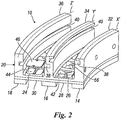
figure 2 is an isometric perspective bottom view of the structure shown infigure 1 ; -
figure 3 is an exploded view of the structure shown infigure 1 ; -
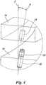
figure 4 is an enlarged view of the detail identified by IV infigure 3 ; -
figure 5 is a perspective view of a portion of a generic articulated-link conveyor that can be used in the structure shown infigure 1 ; and -
figures 6A and 6B show two possible embodiments of fastening means used to secure the guides to the structure shown infigure 1 . - With reference to the figures, a preferred embodiment of the support and magnetic guide structure for an articulated-link conveyor according to the present invention is shown. The support and guide structure is indicated as a whole by the
reference numeral 10, whereas the articulated-link conveyor is indicated by thereference numeral 12. - Even though one portion only of the
conveyor 12 is shown infigure 5 , thisconveyor 12 is a closed-loop one, that is to say designed to cover a forward path and a return path, overlapped to each other, along the support andguide structure 10. Also, the support andguide structure 10 is a magnetic one, that is to say provided with a plurality of magnets (described more in details below) designed to interact with ferromagnetic portions of the links of theconveyor 12. - The support and
guide structure 10 comprises at least twoseparate guides guides guides guides - The
guides link conveyor 12. In the embodiment shown in the figures, the axes of development X, Y, Z are curvilinear and, more specifically, they consist of concentric arcs of circumference. - The support and
guide structure 10 also comprises asupport component 20 which, in turn, comprises at least onefirst surface 22 and at least onesecond surface guides first surface 22, which faces upwards. Pairs ofguides channels such guides first surface 22. Each slidingchannel 28, houses at least one portion of the articulated links of theconveyor 12 in the respective forward path. - In details, in the embodiment shown in the figures, the support and guide
structure 10 comprises one single substantially flatfirst surface 22, designed for receiving three separatecurvilinear guides guides channels conveyors 12 in their forward path in the support and guidestructure 10. - At least two
walls second surface respective grooves guides second surface respective walls figure 1 . Thus, thegrooves link conveyor 12 in its return path. - In the embodiment shown in the figures, which comprises three different
curvilinear guides channels structure 10 comprises three correspondingwalls walls grooves conveyors 12 in their return path in the support and guidestructure 10. - A plurality of
cavities 42 are obtained in thesupport component 20, each designed for housing one ormore magnets 44. Therefore, in the assembled configuration of the support and guidestructure 10, thecavities 42 are open at thesecond surface conveyor 12. Eachcavity 42 is provided with at least oneclosing plate 46, for instance equipped with screws, which encloses thecavity 42 itself and the magnet(s) 44 contained therein. - The
bottom surface 56 of eachcavity 42 is put at a minimum distance from thefirst surface 22 in order to increase the magnetic effect with respect to the links of theconveyor 12. Preferably, thebottom surface 56 of eachcavity 42 is spaced by a distance ranging from 0 mm to 10 mm from thefirst surface 22. Even more preferably, thebottom surface 56 of eachcavity 42 is spaced by a distance ranging from 0 mm to 5 mm from thefirst surface 22. - The
first surface 22, thesecond surface walls first surface 22 can be manufactured with a noble material different from the material with which thesecond surface walls first surface 22 can be fixed to the assembly formed by thesecond surface walls - Advantageously, the
guides first surface 22, thesecond surface walls guides first surface 22, thesecond surface walls guides first surface 22, thesecond surface walls - Preferably, the material with which the
guides guides - Therefore, guides 14, 16 made of the BluLub® material are more smooth-flowing than if using traditional materials. These guides 14, 16, as well as reducing the sliding friction of the links of the
conveyor 12 in the respective support and guidestructure 10, also reduce noise and wear of theguides conveyor 12 move forward. In addition, theguides structure 10, whereas thefirst surface 22 or other parts of the support and guidestructure 10 do not, result in an economical benefit, while providing increased performances for the complete conveying equipment. - Advantageously, the
guides first surface 22. According to the present invention, the fastening means for fixing theguides first surface 22 consist of a plurality of rigid andnon-deformable connection elements hollow seats 52 obtained on saidfirst surface 22 and, on the opposite side, in correspondinghollow seats 54 obtained on eachguide hollow seats hollow seats respective connection elements first surface 22 and of eachguide guides respective support component 20, theseguides hollow seats respective connection elements connection elements guides - Conveniently, should the axes of development X, Y, Z of the
guides grooves structure 10 be curvilinear, at least one part of theconnection elements structure 10, as shown infigure 3 . This tilt counters the centripetal forces which generate while theconveyor 12 moves in the respective slidingchannels - In other words, the more the forces generated by the movement of the conveyor towards the inner circumference of the support and guide
structure 10 increase, the more the respective inner guide (in this specific case consisting of theguide 14 in the attached figures) adheres to thefirst surface 22. Conversely, the outermost guide of the support and guide structure 10 (in this specific case consisting of theguide 18 in the attached figures) does not requireconnection elements conveyor 12. - The
connection elements hollow seat connection elements hollow seats - Preferably, the
connection elements individual guide first rest surface 22, while retaining such fastening reversibility characteristics greater than those which would be obtained, for instance, by using fastening means consisting of screws or bolts. As shown infigures 6A and 6B , the cylindrical plugs 48 might even be provided with one or bothheads 58 having an enlarged cylindrical shape, irrespective of whether the lateral surface is knurled (figure 6B ) or not (figure 6A ). By "enlarged cylindrical shape" we mean that eachhead 58 has an average thickness that is greater than the average thickness of the cross section of its respectivecylindrical plug 48. - Additionally, having hollow seats that are obtained in the lower surface of each
guide first rest surface 22 ofsuch guides guides guides conveyor 12 in its respective forward path, is perfectly flat and uniform, i.e. without any holes which would conversely be necessary when using fastening means consisting of screws or bolts. This is particularly important when using a conveying equipment for moving food products. As a matter of fact, the presence of discontinuities on the sliding surfaces of theconveyor 12 would result in a residual dirt not conforming to the safety standards in force in the sector of food product conveyance. - It has been thus proved that the support and magnetic guide structure for an articulated-link conveyor according to the present invention achieves the previously highlighted objects.
- The support and magnetic guide structure for an articulated-link conveyor according to the thus conceived present invention is however susceptible of numerous modifications and variants, all falling within the scope of one and the same inventive concept; also, all details can be replaced by technically equivalent elements. In practice, the materials used, as well as the shapes and dimensions, might be of any kinds depending on the actual technical requirements.
- Therefore, the scope of protection of the invention is that set forth in the attached claims.
Claims (15)
- A support and guide structure (10) for a closed-loop articulated-link conveyor (12), the support and guide structure (10) comprising:- at least two separate guides (14, 16, 18) arranged at a predefined distance from each other, said guides (14, 16, 18) being oriented along respective development axes (X, Y, Z) and defining respective sliding surfaces for a forward path of the articulated-link conveyor (12);- a support component (20) comprising:the support and guide structure (10) being characterized in that said at least two guides (14, 16, 18) are provided with fastening means (48, 50) which are reversible and removable with respect to said first surface (22), wherein said fastening means consist of a plurality of rigid and non-deformable connection elements (48, 50) designed for being fitted by shape coupling, through friction and without screwing, on one side, in corresponding hollow seats (52) obtained on said first surface (22), and, on the opposite side, in corresponding hollow seats (54) obtained on each guide (14, 16, 18), and wherein said hollow seats (52, 54) do not have any recesses or undercuts.- at least one first surface (22) and at least one second surface (24, 26) opposed to each other, wherein said guides (14, 16, 18) are fastened on said first surface (22) to define at least one sliding channel (28, 30) delimited by said guides (14, 16, 18) and by at least one portion of said first surface (22), said at least one sliding channel (28, 30) housing at least one portion of the articulated links of the conveyor (12) in the respective forward path,- at least two walls (32, 34, 36) which extend from said second surface (24, 26) and comprise respective grooves (38, 40) oriented along respective development axes (X', Y', Z') that are substantially parallel to the development axes (X, Y, Z) of said guides (14, 16, 18), said grooves (38, 40) providing the sliding support of the articulated-link conveyor (12) in its return path, and- a plurality of cavities (42), each designed for housing one or more magnets (44), wherein said cavities (42) are obtained in said support component (20), are open at said second surface (24, 26) and are provided with respective closing plates (46),
- The support and guide structure (10) according to claim 1, characterized in that said hollow seats (52; 54) are oriented along a first axis (A) which is substantially perpendicular to a plane of development of said first surface (22) and of each guide (14, 16, 18), so that each guide (14, 16, 18), should it have to be removed from its respective support component (20), can be lifted along said first axis (A).
- The support and guide structure (10) according to claim 1 or 2, characterized in that at least one part of said hollow seats (52; 54) is tilted by an acute angle (α) with respect to a first axis (A) which is substantially perpendicular to a plane of development of said first surface (22) and of each guide (14, 16, 18), so that each guide (14, 16, 18), should it have to be removed from its respective support component (20), can be lifted along a second axis (B) which is tilted by said angle (α) with respect to said first axis (A).
- The support and guide structure (10) according to claim 3, characterized in that said acute angle (α) is an angle of about 10°.
- The support and guide structure (10) according to any claims 1 to 4, characterized in that said connection elements (48, 50) consist of cylindrical plugs and said hollow seats (52; 54) consist of blind holes featuring a circular cross section.
- The support and guide structure (10) according to any claims 1 to 5, characterized in that said connection elements (48, 50) are provided with a knurled lateral surface.
- The support and guide structure (10) according to any claims 1 to 6, characterized in that the bottom surface (56) of each cavity (42) is spaced by a distance ranging from 0 mm to 10 mm from said first surface (22).
- The support and guide structure (10) according to claim 7, characterized in that said distance ranges from 0 mm to 5 mm from said first surface (22).
- The support and guide structure (10) according to any claims 1 to 8, characterized in that the axes of development (X, Y, Z) of said guides (14, 16, 18) and the corresponding axes of development (X', Y', Z') of said grooves are curvilinear axes.
- The support and guide structure (10) according to claim 9, characterized in that the axes of development (X, Y, Z) of said guides (14, 16, 18) and the corresponding axes of development (X', Y', Z') of said grooves consist of concentric arcs of circumference.
- The support and guide structure (10) according to any claims 1 to 10, characterized in that said at least two guides (14, 16, 18) are manufactured with a material different from the material(s) with which said first surface (22), said second surface (24, 26) and said walls (32, 34, 36) are manufactured.
- The support and guide structure (10) according to claim 11, characterized in that the material with which said at least two guides (14, 16, 18) are manufactured has a coefficient of friction lower than the coefficient of friction of the material(s) with which said first surface (22), said second surface (24, 26) and said walls (32, 34, 36) are manufactured.
- The support and guide structure (10) according to claim 12, characterized in that said coefficient of friction of the material with which said at least two guides (14, 16, 18) are manufactured is lower by at least 10% than said coefficient of friction of the material(s) with which said first surface (22), said second surface (24, 26) and said walls (32, 34, 36) are manufactured.
- The support and guide structure (10) according to any claims 11 to 13, characterized in that the materials with which said first surface (22), said second surface (24, 26), said walls (32, 34, 36) and each guide (14, 16, 18) are manufactured are polymeric materials.
- The support and guide structure (10) according to claim 14, characterized in that the polymeric material with which said first surface (22), said second surface (24, 26) and said walls (32, 34, 36) are manufactured is polythene (PE), whereas the polymeric material with which each guide (14, 16, 18) is manufactured is a ultra-high molecular weight polyethylene (UHMW-PE) with the addition of solid lubricants.
Applications Claiming Priority (1)
| Application Number | Priority Date | Filing Date | Title |
|---|---|---|---|
| IT102018000003682A IT201800003682A1 (en) | 2018-03-16 | 2018-03-16 | SUPPORT STRUCTURE WITH IMPROVED FIXING MEANS FOR AN ARTICULATED LINK CONVEYOR |
Publications (2)
| Publication Number | Publication Date |
|---|---|
| EP3546394A1 true EP3546394A1 (en) | 2019-10-02 |
| EP3546394B1 EP3546394B1 (en) | 2020-12-16 |
Family
ID=62597870
Family Applications (1)
| Application Number | Title | Priority Date | Filing Date |
|---|---|---|---|
| EP19158798.9A Active EP3546394B1 (en) | 2018-03-16 | 2019-02-22 | Support structure with improved fastening means for an articulated-link conveyor |
Country Status (3)
| Country | Link |
|---|---|
| EP (1) | EP3546394B1 (en) |
| ES (1) | ES2863476T3 (en) |
| IT (1) | IT201800003682A1 (en) |
Cited By (6)
| Publication number | Priority date | Publication date | Assignee | Title |
|---|---|---|---|---|
| IT202000021139A1 (en) | 2020-09-07 | 2022-03-07 | Movex S P A | SUPPORT STRUCTURE WITH IMPROVED RIGIDITY FOR AN ARTICULATED LINK CONVEYOR |
| CN114162524A (en) * | 2021-11-04 | 2022-03-11 | 中国矿业大学 | Automatic correcting mechanism for belt of mining conveyor |
| DE202022103780U1 (en) | 2021-07-20 | 2022-07-19 | Movex S.P.A. | Magnetic support and guide structure for an articulated conveyor |
| DE202022103715U1 (en) | 2021-07-20 | 2022-08-03 | Movex S.P.A. | Support structure for an articulated conveyor |
| EP4748753A1 (en) | 2024-11-22 | 2026-05-27 | Movex S.p.A. | Magnetic support and guide structure for one or more conveyors with articulated links |
| EP4763752A1 (en) | 2024-12-19 | 2026-06-24 | Movex S.p.A. | Support and guide element for at least one conveyor with articulated modules |
Citations (5)
| Publication number | Priority date | Publication date | Assignee | Title |
|---|---|---|---|---|
| EP0325333A1 (en) * | 1988-01-19 | 1989-07-26 | REGINA SUD S.p.A. | Improved chain conveyor |
| FR2741053A1 (en) * | 1995-11-14 | 1997-05-16 | Mcc Nederland | Curve guide for chain transporter |
| WO2004035432A1 (en) * | 2002-09-24 | 2004-04-29 | Valu Engineering, Inc. | Conveyor chain guide system |
| US20120152700A1 (en) * | 2009-06-16 | 2012-06-21 | Andrea Andreoli | Bend segment and method for manufacturing a bend segment |
| US20170036861A1 (en) * | 2015-08-06 | 2017-02-09 | System Plast S.Rl. | Curvilinear support for chain conveyors |
Family Cites Families (1)
| Publication number | Priority date | Publication date | Assignee | Title |
|---|---|---|---|---|
| NL2013855B1 (en) * | 2014-11-21 | 2016-10-11 | Rexnord Flattop Europe Bv | A bent segment for a conveyor and method of making. |
-
2018
- 2018-03-16 IT IT102018000003682A patent/IT201800003682A1/en unknown
-
2019
- 2019-02-22 ES ES19158798T patent/ES2863476T3/en active Active
- 2019-02-22 EP EP19158798.9A patent/EP3546394B1/en active Active
Patent Citations (5)
| Publication number | Priority date | Publication date | Assignee | Title |
|---|---|---|---|---|
| EP0325333A1 (en) * | 1988-01-19 | 1989-07-26 | REGINA SUD S.p.A. | Improved chain conveyor |
| FR2741053A1 (en) * | 1995-11-14 | 1997-05-16 | Mcc Nederland | Curve guide for chain transporter |
| WO2004035432A1 (en) * | 2002-09-24 | 2004-04-29 | Valu Engineering, Inc. | Conveyor chain guide system |
| US20120152700A1 (en) * | 2009-06-16 | 2012-06-21 | Andrea Andreoli | Bend segment and method for manufacturing a bend segment |
| US20170036861A1 (en) * | 2015-08-06 | 2017-02-09 | System Plast S.Rl. | Curvilinear support for chain conveyors |
Cited By (9)
| Publication number | Priority date | Publication date | Assignee | Title |
|---|---|---|---|---|
| IT202000021139A1 (en) | 2020-09-07 | 2022-03-07 | Movex S P A | SUPPORT STRUCTURE WITH IMPROVED RIGIDITY FOR AN ARTICULATED LINK CONVEYOR |
| CN114148676A (en) * | 2020-09-07 | 2022-03-08 | 默维狮有限公司 | Support structure with improved stiffness for articulated chain link conveyors |
| EP3964458A1 (en) | 2020-09-07 | 2022-03-09 | Movex S.p.A. | Support structure with improved stiffness for an articulated link conveyor |
| DE202022103780U1 (en) | 2021-07-20 | 2022-07-19 | Movex S.P.A. | Magnetic support and guide structure for an articulated conveyor |
| DE202022103715U1 (en) | 2021-07-20 | 2022-08-03 | Movex S.P.A. | Support structure for an articulated conveyor |
| CN114162524A (en) * | 2021-11-04 | 2022-03-11 | 中国矿业大学 | Automatic correcting mechanism for belt of mining conveyor |
| CN114162524B (en) * | 2021-11-04 | 2022-07-22 | 中国矿业大学 | Automatic correcting mechanism for belt of mining conveyor |
| EP4748753A1 (en) | 2024-11-22 | 2026-05-27 | Movex S.p.A. | Magnetic support and guide structure for one or more conveyors with articulated links |
| EP4763752A1 (en) | 2024-12-19 | 2026-06-24 | Movex S.p.A. | Support and guide element for at least one conveyor with articulated modules |
Also Published As
| Publication number | Publication date |
|---|---|
| EP3546394B1 (en) | 2020-12-16 |
| ES2863476T3 (en) | 2021-10-11 |
| IT201800003682A1 (en) | 2019-09-16 |
Similar Documents
| Publication | Publication Date | Title |
|---|---|---|
| EP3546394B1 (en) | Support structure with improved fastening means for an articulated-link conveyor | |
| EP2055655B1 (en) | Conveyor frame assembly | |
| EP2907774B1 (en) | Guiding rail for a table-top chain | |
| CA2042942C (en) | Modular conveyor belt | |
| EP2509895B1 (en) | Conveyor transfer system with floating transfer platform | |
| CN104395208B (en) | Conveyer chain link, conveyor chains and include the transmitter system of conveyor chains | |
| US9751694B2 (en) | Side-flexing conveyors | |
| EP0325333B1 (en) | Improved chain conveyor | |
| EP0903307B1 (en) | Improved magnetic guide | |
| EP3572358B1 (en) | Support structure with improved bottom for an articulated link conveyor | |
| US9205986B2 (en) | Conveyor chain link, conveyor chain, drive wheel for a conveyor chain and a system comprising such a drive wheel | |
| EP3763640B1 (en) | Improved guiding device for bulk goods conveyors | |
| EP3655350B1 (en) | Improved modular structure curved magnetic guide for guiding the chain of a conveyor chain | |
| US12145804B2 (en) | Conveyor belt module with wear pads | |
| NL2022740B1 (en) | Support structure with improved guides for an articulated-link conveyor | |
| EP3964458B1 (en) | Support structure with improved stiffness for an articulated link conveyor | |
| EP2240392B1 (en) | Return guide bend segment | |
| CN122071336A (en) | Magnetic support and guide structure for one or more transport elements with hinged links | |
| WO2001014225A1 (en) | Guide for conveyor chain | |
| WO2016092500A1 (en) | Link for chain for articles conveyor |
Legal Events
| Date | Code | Title | Description |
|---|---|---|---|
| PUAI | Public reference made under article 153(3) epc to a published international application that has entered the european phase |
Free format text: ORIGINAL CODE: 0009012 |
|
| STAA | Information on the status of an ep patent application or granted ep patent |
Free format text: STATUS: THE APPLICATION HAS BEEN PUBLISHED |
|
| AK | Designated contracting states |
Kind code of ref document: A1 Designated state(s): AL AT BE BG CH CY CZ DE DK EE ES FI FR GB GR HR HU IE IS IT LI LT LU LV MC MK MT NL NO PL PT RO RS SE SI SK SM TR |
|
| AX | Request for extension of the european patent |
Extension state: BA ME |
|
| STAA | Information on the status of an ep patent application or granted ep patent |
Free format text: STATUS: REQUEST FOR EXAMINATION WAS MADE |
|
| 17P | Request for examination filed |
Effective date: 20200227 |
|
| RBV | Designated contracting states (corrected) |
Designated state(s): AL AT BE BG CH CY CZ DE DK EE ES FI FR GB GR HR HU IE IS IT LI LT LU LV MC MK MT NL NO PL PT RO RS SE SI SK SM TR |
|
| GRAP | Despatch of communication of intention to grant a patent |
Free format text: ORIGINAL CODE: EPIDOSNIGR1 |
|
| STAA | Information on the status of an ep patent application or granted ep patent |
Free format text: STATUS: GRANT OF PATENT IS INTENDED |
|
| INTG | Intention to grant announced |
Effective date: 20200728 |
|
| GRAS | Grant fee paid |
Free format text: ORIGINAL CODE: EPIDOSNIGR3 |
|
| GRAA | (expected) grant |
Free format text: ORIGINAL CODE: 0009210 |
|
| STAA | Information on the status of an ep patent application or granted ep patent |
Free format text: STATUS: THE PATENT HAS BEEN GRANTED |
|
| AK | Designated contracting states |
Kind code of ref document: B1 Designated state(s): AL AT BE BG CH CY CZ DE DK EE ES FI FR GB GR HR HU IE IS IT LI LT LU LV MC MK MT NL NO PL PT RO RS SE SI SK SM TR |
|
| REG | Reference to a national code |
Ref country code: GB Ref legal event code: FG4D |
|
| REG | Reference to a national code |
Ref country code: DE Ref legal event code: R096 Ref document number: 602019001704 Country of ref document: DE |
|
| REG | Reference to a national code |
Ref country code: IE Ref legal event code: FG4D |
|
| REG | Reference to a national code |
Ref country code: AT Ref legal event code: REF Ref document number: 1345397 Country of ref document: AT Kind code of ref document: T Effective date: 20210115 |
|
| REG | Reference to a national code |
Ref country code: NL Ref legal event code: FP |
|
| PG25 | Lapsed in a contracting state [announced via postgrant information from national office to epo] |
Ref country code: NO Free format text: LAPSE BECAUSE OF FAILURE TO SUBMIT A TRANSLATION OF THE DESCRIPTION OR TO PAY THE FEE WITHIN THE PRESCRIBED TIME-LIMIT Effective date: 20210316 Ref country code: GR Free format text: LAPSE BECAUSE OF FAILURE TO SUBMIT A TRANSLATION OF THE DESCRIPTION OR TO PAY THE FEE WITHIN THE PRESCRIBED TIME-LIMIT Effective date: 20210317 Ref country code: RS Free format text: LAPSE BECAUSE OF FAILURE TO SUBMIT A TRANSLATION OF THE DESCRIPTION OR TO PAY THE FEE WITHIN THE PRESCRIBED TIME-LIMIT Effective date: 20201216 Ref country code: FI Free format text: LAPSE BECAUSE OF FAILURE TO SUBMIT A TRANSLATION OF THE DESCRIPTION OR TO PAY THE FEE WITHIN THE PRESCRIBED TIME-LIMIT Effective date: 20201216 |
|
| REG | Reference to a national code |
Ref country code: AT Ref legal event code: MK05 Ref document number: 1345397 Country of ref document: AT Kind code of ref document: T Effective date: 20201216 |
|
| PG25 | Lapsed in a contracting state [announced via postgrant information from national office to epo] |
Ref country code: SE Free format text: LAPSE BECAUSE OF FAILURE TO SUBMIT A TRANSLATION OF THE DESCRIPTION OR TO PAY THE FEE WITHIN THE PRESCRIBED TIME-LIMIT Effective date: 20201216 Ref country code: LV Free format text: LAPSE BECAUSE OF FAILURE TO SUBMIT A TRANSLATION OF THE DESCRIPTION OR TO PAY THE FEE WITHIN THE PRESCRIBED TIME-LIMIT Effective date: 20201216 Ref country code: BG Free format text: LAPSE BECAUSE OF FAILURE TO SUBMIT A TRANSLATION OF THE DESCRIPTION OR TO PAY THE FEE WITHIN THE PRESCRIBED TIME-LIMIT Effective date: 20210316 |
|
| PG25 | Lapsed in a contracting state [announced via postgrant information from national office to epo] |
Ref country code: HR Free format text: LAPSE BECAUSE OF FAILURE TO SUBMIT A TRANSLATION OF THE DESCRIPTION OR TO PAY THE FEE WITHIN THE PRESCRIBED TIME-LIMIT Effective date: 20201216 |
|
| REG | Reference to a national code |
Ref country code: LT Ref legal event code: MG9D |
|
| PG25 | Lapsed in a contracting state [announced via postgrant information from national office to epo] |
Ref country code: EE Free format text: LAPSE BECAUSE OF FAILURE TO SUBMIT A TRANSLATION OF THE DESCRIPTION OR TO PAY THE FEE WITHIN THE PRESCRIBED TIME-LIMIT Effective date: 20201216 Ref country code: SM Free format text: LAPSE BECAUSE OF FAILURE TO SUBMIT A TRANSLATION OF THE DESCRIPTION OR TO PAY THE FEE WITHIN THE PRESCRIBED TIME-LIMIT Effective date: 20201216 Ref country code: SK Free format text: LAPSE BECAUSE OF FAILURE TO SUBMIT A TRANSLATION OF THE DESCRIPTION OR TO PAY THE FEE WITHIN THE PRESCRIBED TIME-LIMIT Effective date: 20201216 Ref country code: CZ Free format text: LAPSE BECAUSE OF FAILURE TO SUBMIT A TRANSLATION OF THE DESCRIPTION OR TO PAY THE FEE WITHIN THE PRESCRIBED TIME-LIMIT Effective date: 20201216 Ref country code: LT Free format text: LAPSE BECAUSE OF FAILURE TO SUBMIT A TRANSLATION OF THE DESCRIPTION OR TO PAY THE FEE WITHIN THE PRESCRIBED TIME-LIMIT Effective date: 20201216 Ref country code: RO Free format text: LAPSE BECAUSE OF FAILURE TO SUBMIT A TRANSLATION OF THE DESCRIPTION OR TO PAY THE FEE WITHIN THE PRESCRIBED TIME-LIMIT Effective date: 20201216 Ref country code: PT Free format text: LAPSE BECAUSE OF FAILURE TO SUBMIT A TRANSLATION OF THE DESCRIPTION OR TO PAY THE FEE WITHIN THE PRESCRIBED TIME-LIMIT Effective date: 20210416 |
|
| PG25 | Lapsed in a contracting state [announced via postgrant information from national office to epo] |
Ref country code: PL Free format text: LAPSE BECAUSE OF FAILURE TO SUBMIT A TRANSLATION OF THE DESCRIPTION OR TO PAY THE FEE WITHIN THE PRESCRIBED TIME-LIMIT Effective date: 20201216 Ref country code: AT Free format text: LAPSE BECAUSE OF FAILURE TO SUBMIT A TRANSLATION OF THE DESCRIPTION OR TO PAY THE FEE WITHIN THE PRESCRIBED TIME-LIMIT Effective date: 20201216 |
|
| REG | Reference to a national code |
Ref country code: DE Ref legal event code: R097 Ref document number: 602019001704 Country of ref document: DE |
|
| PG25 | Lapsed in a contracting state [announced via postgrant information from national office to epo] |
Ref country code: IS Free format text: LAPSE BECAUSE OF FAILURE TO SUBMIT A TRANSLATION OF THE DESCRIPTION OR TO PAY THE FEE WITHIN THE PRESCRIBED TIME-LIMIT Effective date: 20210416 Ref country code: MC Free format text: LAPSE BECAUSE OF FAILURE TO SUBMIT A TRANSLATION OF THE DESCRIPTION OR TO PAY THE FEE WITHIN THE PRESCRIBED TIME-LIMIT Effective date: 20201216 |
|
| REG | Reference to a national code |
Ref country code: ES Ref legal event code: FG2A Ref document number: 2863476 Country of ref document: ES Kind code of ref document: T3 Effective date: 20211011 |
|
| PLBE | No opposition filed within time limit |
Free format text: ORIGINAL CODE: 0009261 |
|
| STAA | Information on the status of an ep patent application or granted ep patent |
Free format text: STATUS: NO OPPOSITION FILED WITHIN TIME LIMIT |
|
| REG | Reference to a national code |
Ref country code: BE Ref legal event code: MM Effective date: 20210228 |
|
| PG25 | Lapsed in a contracting state [announced via postgrant information from national office to epo] |
Ref country code: AL Free format text: LAPSE BECAUSE OF FAILURE TO SUBMIT A TRANSLATION OF THE DESCRIPTION OR TO PAY THE FEE WITHIN THE PRESCRIBED TIME-LIMIT Effective date: 20201216 Ref country code: LU Free format text: LAPSE BECAUSE OF NON-PAYMENT OF DUE FEES Effective date: 20210222 |
|
| 26N | No opposition filed |
Effective date: 20210917 |
|
| PG25 | Lapsed in a contracting state [announced via postgrant information from national office to epo] |
Ref country code: DK Free format text: LAPSE BECAUSE OF FAILURE TO SUBMIT A TRANSLATION OF THE DESCRIPTION OR TO PAY THE FEE WITHIN THE PRESCRIBED TIME-LIMIT Effective date: 20201216 |
|
| PG25 | Lapsed in a contracting state [announced via postgrant information from national office to epo] |
Ref country code: FR Free format text: LAPSE BECAUSE OF NON-PAYMENT OF DUE FEES Effective date: 20210228 Ref country code: IE Free format text: LAPSE BECAUSE OF NON-PAYMENT OF DUE FEES Effective date: 20210222 |
|
| PG25 | Lapsed in a contracting state [announced via postgrant information from national office to epo] |
Ref country code: SI Free format text: LAPSE BECAUSE OF FAILURE TO SUBMIT A TRANSLATION OF THE DESCRIPTION OR TO PAY THE FEE WITHIN THE PRESCRIBED TIME-LIMIT Effective date: 20201216 |
|
| PG25 | Lapsed in a contracting state [announced via postgrant information from national office to epo] |
Ref country code: IS Free format text: LAPSE BECAUSE OF FAILURE TO SUBMIT A TRANSLATION OF THE DESCRIPTION OR TO PAY THE FEE WITHIN THE PRESCRIBED TIME-LIMIT Effective date: 20210416 |
|
| PG25 | Lapsed in a contracting state [announced via postgrant information from national office to epo] |
Ref country code: BE Free format text: LAPSE BECAUSE OF NON-PAYMENT OF DUE FEES Effective date: 20210228 |
|
| REG | Reference to a national code |
Ref country code: CH Ref legal event code: PL |
|
| PG25 | Lapsed in a contracting state [announced via postgrant information from national office to epo] |
Ref country code: LI Free format text: LAPSE BECAUSE OF NON-PAYMENT OF DUE FEES Effective date: 20220228 Ref country code: CH Free format text: LAPSE BECAUSE OF NON-PAYMENT OF DUE FEES Effective date: 20220228 |
|
| PG25 | Lapsed in a contracting state [announced via postgrant information from national office to epo] |
Ref country code: CY Free format text: LAPSE BECAUSE OF FAILURE TO SUBMIT A TRANSLATION OF THE DESCRIPTION OR TO PAY THE FEE WITHIN THE PRESCRIBED TIME-LIMIT Effective date: 20201216 |
|
| PG25 | Lapsed in a contracting state [announced via postgrant information from national office to epo] |
Ref country code: HU Free format text: LAPSE BECAUSE OF FAILURE TO SUBMIT A TRANSLATION OF THE DESCRIPTION OR TO PAY THE FEE WITHIN THE PRESCRIBED TIME-LIMIT; INVALID AB INITIO Effective date: 20190222 |
|
| P01 | Opt-out of the competence of the unified patent court (upc) registered |
Effective date: 20230626 |
|
| PG25 | Lapsed in a contracting state [announced via postgrant information from national office to epo] |
Ref country code: MK Free format text: LAPSE BECAUSE OF FAILURE TO SUBMIT A TRANSLATION OF THE DESCRIPTION OR TO PAY THE FEE WITHIN THE PRESCRIBED TIME-LIMIT Effective date: 20201216 |
|
| PG25 | Lapsed in a contracting state [announced via postgrant information from national office to epo] |
Ref country code: TR Free format text: LAPSE BECAUSE OF FAILURE TO SUBMIT A TRANSLATION OF THE DESCRIPTION OR TO PAY THE FEE WITHIN THE PRESCRIBED TIME-LIMIT Effective date: 20201216 |
|
| PG25 | Lapsed in a contracting state [announced via postgrant information from national office to epo] |
Ref country code: MT Free format text: LAPSE BECAUSE OF FAILURE TO SUBMIT A TRANSLATION OF THE DESCRIPTION OR TO PAY THE FEE WITHIN THE PRESCRIBED TIME-LIMIT Effective date: 20201216 |
|
| PGFP | Annual fee paid to national office [announced via postgrant information from national office to epo] |
Ref country code: NL Payment date: 20260226 Year of fee payment: 8 |
|
| PGFP | Annual fee paid to national office [announced via postgrant information from national office to epo] |
Ref country code: GB Payment date: 20260223 Year of fee payment: 8 |
|
| PGFP | Annual fee paid to national office [announced via postgrant information from national office to epo] |
Ref country code: ES Payment date: 20260302 Year of fee payment: 8 |
|
| PGFP | Annual fee paid to national office [announced via postgrant information from national office to epo] |
Ref country code: DE Payment date: 20260217 Year of fee payment: 8 |
|
| PGFP | Annual fee paid to national office [announced via postgrant information from national office to epo] |
Ref country code: IT Payment date: 20260122 Year of fee payment: 8 |