EP3546368B1 - Einlassdiffusor für strahltriebwerk und verfahren zur diffusion von eintretender luft vom strahltriebwerk - Google Patents
Einlassdiffusor für strahltriebwerk und verfahren zur diffusion von eintretender luft vom strahltriebwerk Download PDFInfo
- Publication number
- EP3546368B1 EP3546368B1 EP19156786.6A EP19156786A EP3546368B1 EP 3546368 B1 EP3546368 B1 EP 3546368B1 EP 19156786 A EP19156786 A EP 19156786A EP 3546368 B1 EP3546368 B1 EP 3546368B1
- Authority
- EP
- European Patent Office
- Prior art keywords
- boundary layer
- layer air
- inlet
- internal surface
- inlet diffuser
- Prior art date
- Legal status (The legal status is an assumption and is not a legal conclusion. Google has not performed a legal analysis and makes no representation as to the accuracy of the status listed.)
- Active
Links
Images




Classifications
-
- F—MECHANICAL ENGINEERING; LIGHTING; HEATING; WEAPONS; BLASTING
- F02—COMBUSTION ENGINES; HOT-GAS OR COMBUSTION-PRODUCT ENGINE PLANTS
- F02C—GAS-TURBINE PLANTS; AIR INTAKES FOR JET-PROPULSION PLANTS; CONTROLLING FUEL SUPPLY IN AIR-BREATHING JET-PROPULSION PLANTS
- F02C7/00—Features, components parts, details or accessories, not provided for in, or of interest apart form groups F02C1/00 - F02C6/00; Air intakes for jet-propulsion plants
- F02C7/04—Air intakes for gas-turbine plants or jet-propulsion plants
- F02C7/042—Air intakes for gas-turbine plants or jet-propulsion plants having variable geometry
-
- B—PERFORMING OPERATIONS; TRANSPORTING
- B64—AIRCRAFT; AVIATION; COSMONAUTICS
- B64D—EQUIPMENT FOR FITTING IN OR TO AIRCRAFT; FLIGHT SUITS; PARACHUTES; ARRANGEMENT OR MOUNTING OF POWER PLANTS OR PROPULSION TRANSMISSIONS IN AIRCRAFT
- B64D27/00—Arrangement or mounting of power plants in aircraft; Aircraft characterised by the type or position of power plants
- B64D27/02—Aircraft characterised by the type or position of power plants
- B64D27/16—Aircraft characterised by the type or position of power plants of jet type
-
- B—PERFORMING OPERATIONS; TRANSPORTING
- B64—AIRCRAFT; AVIATION; COSMONAUTICS
- B64D—EQUIPMENT FOR FITTING IN OR TO AIRCRAFT; FLIGHT SUITS; PARACHUTES; ARRANGEMENT OR MOUNTING OF POWER PLANTS OR PROPULSION TRANSMISSIONS IN AIRCRAFT
- B64D33/00—Arrangement in aircraft of power plant parts or auxiliaries not otherwise provided for
- B64D33/02—Arrangement in aircraft of power plant parts or auxiliaries not otherwise provided for of combustion air intakes
-
- F—MECHANICAL ENGINEERING; LIGHTING; HEATING; WEAPONS; BLASTING
- F02—COMBUSTION ENGINES; HOT-GAS OR COMBUSTION-PRODUCT ENGINE PLANTS
- F02C—GAS-TURBINE PLANTS; AIR INTAKES FOR JET-PROPULSION PLANTS; CONTROLLING FUEL SUPPLY IN AIR-BREATHING JET-PROPULSION PLANTS
- F02C7/00—Features, components parts, details or accessories, not provided for in, or of interest apart form groups F02C1/00 - F02C6/00; Air intakes for jet-propulsion plants
- F02C7/04—Air intakes for gas-turbine plants or jet-propulsion plants
-
- F—MECHANICAL ENGINEERING; LIGHTING; HEATING; WEAPONS; BLASTING
- F04—POSITIVE - DISPLACEMENT MACHINES FOR LIQUIDS; PUMPS FOR LIQUIDS OR ELASTIC FLUIDS
- F04D—NON-POSITIVE-DISPLACEMENT PUMPS
- F04D29/00—Details, component parts, or accessories
- F04D29/40—Casings; Connections of working fluid
- F04D29/52—Casings; Connections of working fluid for axial pumps
- F04D29/54—Fluid-guiding means, e.g. diffusers
- F04D29/541—Specially adapted for elastic fluid pumps
-
- B—PERFORMING OPERATIONS; TRANSPORTING
- B64—AIRCRAFT; AVIATION; COSMONAUTICS
- B64D—EQUIPMENT FOR FITTING IN OR TO AIRCRAFT; FLIGHT SUITS; PARACHUTES; ARRANGEMENT OR MOUNTING OF POWER PLANTS OR PROPULSION TRANSMISSIONS IN AIRCRAFT
- B64D33/00—Arrangement in aircraft of power plant parts or auxiliaries not otherwise provided for
- B64D33/02—Arrangement in aircraft of power plant parts or auxiliaries not otherwise provided for of combustion air intakes
- B64D2033/0226—Arrangement in aircraft of power plant parts or auxiliaries not otherwise provided for of combustion air intakes comprising boundary layer control means
-
- B—PERFORMING OPERATIONS; TRANSPORTING
- B64—AIRCRAFT; AVIATION; COSMONAUTICS
- B64D—EQUIPMENT FOR FITTING IN OR TO AIRCRAFT; FLIGHT SUITS; PARACHUTES; ARRANGEMENT OR MOUNTING OF POWER PLANTS OR PROPULSION TRANSMISSIONS IN AIRCRAFT
- B64D33/00—Arrangement in aircraft of power plant parts or auxiliaries not otherwise provided for
- B64D33/02—Arrangement in aircraft of power plant parts or auxiliaries not otherwise provided for of combustion air intakes
- B64D2033/0266—Arrangement in aircraft of power plant parts or auxiliaries not otherwise provided for of combustion air intakes specially adapted for particular type of power plants
- B64D2033/0273—Arrangement in aircraft of power plant parts or auxiliaries not otherwise provided for of combustion air intakes specially adapted for particular type of power plants for jet engines
-
- F—MECHANICAL ENGINEERING; LIGHTING; HEATING; WEAPONS; BLASTING
- F05—INDEXING SCHEMES RELATING TO ENGINES OR PUMPS IN VARIOUS SUBCLASSES OF CLASSES F01-F04
- F05D—INDEXING SCHEME FOR ASPECTS RELATING TO NON-POSITIVE-DISPLACEMENT MACHINES OR ENGINES, GAS-TURBINES OR JET-PROPULSION PLANTS
- F05D2220/00—Application
- F05D2220/30—Application in turbines
- F05D2220/32—Application in turbines in gas turbines
- F05D2220/323—Application in turbines in gas turbines for aircraft propulsion, e.g. jet engines
-
- F—MECHANICAL ENGINEERING; LIGHTING; HEATING; WEAPONS; BLASTING
- F05—INDEXING SCHEMES RELATING TO ENGINES OR PUMPS IN VARIOUS SUBCLASSES OF CLASSES F01-F04
- F05D—INDEXING SCHEME FOR ASPECTS RELATING TO NON-POSITIVE-DISPLACEMENT MACHINES OR ENGINES, GAS-TURBINES OR JET-PROPULSION PLANTS
- F05D2240/00—Components
- F05D2240/10—Stators
- F05D2240/12—Fluid guiding means, e.g. vanes
- F05D2240/127—Vortex generators, turbulators, or the like, for mixing
Definitions
- the present disclosure relates to inlet diffusers for jet engines.
- Aircraft propulsion systems may use an inlet diffuser to govern the introduction of ambient air into the aircraft engine.
- an inlet diffuser to govern the introduction of ambient air into the aircraft engine.
- some current aircraft propulsion systems use high aspect ratio inlets that have a very wide opening which transitions to a circular engine face.
- Boundary layer air can cause total pressure recovery loss and total pressure distortions which can cause an engine to stall.
- some systems use a boundary layer diverter to prevent boundary layer air from entering the inlet diffuser.
- boundary layer diverters can reduce the aerodynamics of an aircraft, which slows down the speed and efficiency of an aircraft. Therefore, it is desired to have a new inlet diffuser for jet engines that prevents boundary layer air from disrupting engine performance while only minimally affecting the aerodynamics of the aircraft.
- a supersonic diffuser has a plurality of blades therein for dividing the diffuser channel into a plurality of approximately axisymmetric ducts wherein a portion of said ducts ingest a boundary layer along at least one of the walls of the supersonic diffuser.
- the blades in the diffuser channel have their upstream ends bent away from the wall having the boundary layer to redirect the flow into the ducts.
- the wall between the duct having the boundary layer and the duct adjacent to the duct having the boundary layer is made in two sections with both sections being bent away from the wall having the boundary layer.
- an air inlet for aircraft operating at supersonic speeds comprises a flow passage disposed substantially in line with the air stream, said flow passage having a forwardly facing opening in the air stream, and means in said flow passage to enable the passage to accept and decelerate the air with low external compression and with high pressure recovery.
- Said means comprising at least one vane extending across the passage at the inlet end thereof, said vane extending downstream from adjacent the inlet end of said passage and having a streamlined bulge intermediate its upstream and downstream edges, whereby to form a convergent divergent passage.
- a straightening apparatus constituted by a diffuser connected to an inflow pipe has a rectangular section to form an enlarged channel, and eight straightening vanes arranged inside the diffuser.
- the diffuser has a rectangular sectional surface and is formed to increase its sectional area from a channel inlet to an outlet.
- Each straightening vane is arranged to set its surface along the flow direction. Instead of completely partitioning the channel by one straightening vane, the straightening vanes are respectively arranged on the upstream and downstream sides in the flow direction at intervals to form an opening portion at the middle portion of the channel without any partition.
- US 2477637 A states that a sheath straddles a trailing edge of the wing at its point of juncture with a fuselage of an aircraft to provide air channels at the upper and lower surfaces thereof.
- the sheath has one edge, above the encased wing extending longitudinally of the wing to define the mouth of one channel, and having another edge opening laterally into the interior of the fuselage to discharge the air received by it from said air channels, and means carried by said fuselage creating a forced draft of air for sucking the air into the fuselage and serving to expel the air from the rear end of the fuselage.
- Inlet diffusers for jet engines, jet engines, jet aircraft, and methods for diffusing incoming air of jet engines are disclosed.
- An inlet diffuser for a jet engine is defined in the independent claim 1. Further embodiments are defined in the dependent claims 2-12.
- a method for mixing boundary layers is defined in the independent claim 13. Further steps can be found in the dependent claims 14-15.
- Inlet diffusers for jet engines, jet engines, jet aircraft, and methods for mixing incoming boundary layer air of inlet diffusers are disclosed.
- elements that are likely to be included in a given example are illustrated in solid lines, while elements that are optional to a given example are illustrated in broken lines.
- elements that are illustrated in solid lines are not essential to all examples of the present disclosure, and an element shown in solid lines may be omitted from a particular example without departing from the scope of the present disclosure.
- Fig. 1 is a schematic and perspective view of illustrative, non-exclusive example of an aircraft 100 using inlet diffusers 10 according to the present disclosure.
- aircraft 100 may include an aircraft body 120 to which one or more engines 130 are secured, such as to provide thrust to aircraft 100.
- Engines 130 may include jet engines and may be referred to herein as jet engines 130.
- engine 130 may be a gas turbine engine that includes elements such as a compressor 132, a burner 134, a turbine 136, an exit nozzle 138, etc.
- Inlet diffusers 10 may be operatively connected to engines 130 to govern ambient air that is allowed to pass into the engine 130.
- Aircraft 100 generally may be utilized to transport persons, cargo, and/or other payload, and may be a commercial aircraft, a military aircraft, etc.
- An aircraft 100 that utilizes at least one engine 130 according to the present disclosure generally may be configured to operate at subsonic speeds, and/or supersonic speeds.
- inlet diffusers 10 include a diffuser body 14 that defines an internal volume 16, an inlet aperture 12 by which ambient air enters the internal volume 16, and an exit aperture 18 by which air passes from the internal volume 16 of the inlet diffuser 10 to a downstream portion of the engine 130.
- the inlet aperture 12 is shown in Fig. 1 as having a maximum width 40, a maximum height 50, and a high aspect ratio.
- the term high aspect ratio refers to the relationships between maximum width 40 and maximum height 50 where the maximum width 40 is at least 2, at least 3, at least 4, or at least 5 times the maximum height 50.
- Fig. 1 also illustrates inlet aperture 12 as having a trapezoidal shape, however other shapes having a high aperture ratio may also be used, such as rectangles, ovoids, a circle segment, etc.
- Exit aperture 18 is depicted in Fig. 1 as having a circular profile having a diameter 52; however other shapes also may be used.
- a shape of exit aperture 18 may correspond to a shape of a downstream element of the engine 130 with which the exit aperture 18 interfaces.
- Fig. 1 also illustrates the inlet aperture 12 as being offset from the exit aperture 18 by an offset distance 54.
- the term offset is used to refer to the minimum translational distance between a normal 42 extending from a center point of a perpendicular cross section of the inlet aperture 12 and a normal 44 extending from a center point of a perpendicular cross section of the exit aperture 18, where the perpendicular cross section of the inlet aperture 12 and the perpendicular cross section of the exit aperture 18 are parallel planes.
- the inlet diffuser 10 also includes an internal surface 20 that faces the internal volume 16.
- the internal surface 20 has a fore region 22 that is proximate to the inlet aperture 12 and an aft region 24 downstream of the fore region 22 and proximate to the exit aperture 18.
- the internal surface 20 has a centerline 80 that bisects the internal surface 20 and extends from the inlet aperture 12 to the exit aperture 18.
- outboard is used to represent a direction away from and perpendicular to the centerline 80 of the internal surface 20 parallel to the internal surface 20
- the term inboard is used to represent a direction toward and perpendicular to the centerline 80 of the internal surface 20 parallel to the internal surface 20.
- the internal surface 20 also includes an offset slope surface 26 that is downstream of the fore region 22.
- the offset slope surface 26 is a portion of the internal surface 20 that is sloped so as to compensate for the offset distance 54.
- the offset nature of the inlet diffusers 10 may cause flow separation as air passes through the internal volume 16 of the inlet diffuser 10.
- a boundary layer of air is formed along the internal surface 20 when ambient air enters the inlet diffuser 10.
- the boundary layer of air corresponds to the layer of air near the internal surface 20 in which a velocity changes from zero at the internal surface 20, to a velocity of the high energy airflow located away from the internal surface 20.
- a portion of the boundary layer of air may lift and move away from the internal surface 20.
- a portion of the boundary layer of air may be pulled away from the internal surface 20 due to pressure differences between the lower velocity boundary layer air and the higher velocity high energy airflow. If this type of pulling/mixing occurs too far from the internal surface 20, it can create airflow total pressure distortions that may cause a jet engine 130 operationally coupled to the inlet diffuser 10 to stall.
- inlet diffuser 10 of the present disclosure includes elongate structures 30 to enhance boundary layer mixing, minimize boundary layer airflow from lifting off surface 20, and reduce the likelihood of engines 130 from stalling due to such airflow pressure distortions.
- elongate structures 30 additionally or alternatively may be described as mixing devices or mixing structures. Certain embodiments disclosed herein are especially effective at minimizing such engine stalls in compact inlet diffusers with high offset and/or high aspect ratio apertures.
- the elongate structures 30 may include a pair of elongate structures 30 extending longitudinally along the internal surface 20. Each of the pair of elongate structures 30 includes a front end 32 that is located on the fore region 22 and a rear end 34 that is located on the aft region 24.
- each of the pair of elongate structures 30 may be equally spaced from the centerline 80 of the internal surface 20.
- the elongate structures 30 may be integrally formed with the internal surface 20 of the inlet diffuser 10.
- the elongate structures 30 may be coupled to the internal surface 20 via one or more coupling methods such as bonding, bolting, welding, etc.
- the elongate structures 30 may be composed of the same material as the internal surface 20, and/or one or more other materials.
- the pair of elongate structures 30 defines a channel 70 of the internal volume 16 inboard of the elongate structures 30.
- the channel 70 may be a subvolume of the internal volume 16 that is bordered on three elongate sides by a first elongate structure, a portion of the internal surface 20, and a second elongate structure, with a fourth elongate side and the two opposing end sides of the channel 70 (proximate to the inlet aperture 12 and the exit aperture 18, respectively) being open to the internal volume 16.
- the boundary layer of air within the internal volume 16 is split into a first portion 36 of boundary layer air and a second portion 38 of boundary layer air.
- the boundary layer of air may be split by the front ends 32 of the elongate structures 30 into the first portion 36 of boundary layer air that is located between the elongate structures 30 (i.e., within the channel 70), and the second portion 38 of boundary layer air that is located outboard of the elongate structures 30 on a first outboard side of the elongate structures 30, a second outboard side of the elongate structures 30, or both.
- the first portion 36 of boundary layer air may be located between second portions 38 of boundary layer air.
- the elongate structures 30 are configured to allow the first portion 36 of boundary layer air to flow along the internal surface 20 from the fore region 22 to the aft region 24.
- the elongate structures 30 are configured to restrict air from flowing from the channel 70 in an outboard direction.
- each elongate structure 30 may form a barrier on a respective outboard side of the channel 70 that prevents a flow of the first portion 36 of boundary layer air across the barrier.
- the elongate structures 30 also may restrict, or in some instances prevent, the second portions 38 of boundary layer air from moving in an inboard direction into the channel 70. In this way, the elongate structures 30 allow the first portion 36 of boundary layer air to flow towards the exit aperture 18 without spreading in an outboard direction or being swept up by inboard movement of second portions 38 of boundary layer air.
- the elongate structures 30 also are configured so that second portions 38 of boundary layer air are allowed to move in an inboard direction across the elongate structures 30. Moreover, a ramp face of the elongate structures 30 is sloped so that second portions 38 of boundary layer air are pushed away from the internal surface 20 of the inlet diffuser 10 as they travel across the ramp face in an inboard direction. In this way, when a given second portion 38 of boundary layer air is displaced in an inboard direction across the elongate structures 30, it is guided by the surface of the corresponding elongate structure into a region of space inward of the first portion 36 of boundary layer air within the channel 70.
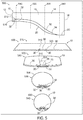
- Figs. 5-7 illustrate the gradual mixing of boundary layer air in various example embodiments of the inlet diffusers of the present disclosure. Because the sloped surface of the elongate structures 30 may extend along their entire length, the elongate structures 30 may facilitate a gradual mixing of the second portions 38 of boundary layer air along a length 60 of the inlet diffuser 10. In this way, the strength of the vortex caused by the mixing of the two portions of boundary layer air is reduced.
- Fig. 2 is a schematic top down diagram illustrating an example of inlet diffuser inlet 10 that includes a pair of elongate structures 30.
- Fig. 2 shows the pair of elongate structures 30 located on the internal surface 20 of the inlet diffuser 10.
- Each elongate structure 30 is shown as having the front end 32 proximate to the inlet aperture 12 and the rear end 34 downstream of the front end 32.
- the front ends 32 are shown as corresponding to flat ends 210
- the rear ends 34 are shown as corresponding to angled ends 212.
- one or more of the front end 32 and the rear end 34 may correspond to a flat end 210, an angled end 212, and/or a curved end 214.
- a portion of internal surface 20 is shown as being disposed between the front end 32 of the elongate structures 30 and the inlet aperture 12.
- the front end 32 of a respective elongate structure 30 may be aligned with the inlet aperture 12.
- Fig. 2 further illustrates an example of inlet diffuser 10, wherein centerline 80 bisects the internal surface 20 of the inlet diffuser 10.
- each elongate structure 30 is equally spaced from the centerline 80.
- Fig. 2 shows channel 70 located inboard of each of the elongate structures 30 through which boundary layer air is able to flow from the inlet aperture 12 downstream to the exit aperture 18 of the inlet diffuser 10.
- An inboard surface 82 of each elongate structure 30 may form barriers that prevent boundary layer air from flowing out of the channel 70 in an outboard direction.
- Fig. 2 shows channel 70 as having a constant width (i.e., the distance between the inboard surfaces 82 of the elongate structures 30 is constant along the length of the channel 70).
- the internal volume 16 of the inlet diffuser 10 may narrow in an inboard direction between the inlet aperture 12 and the exit aperture 18. This narrowing of the internal volume 16 is indicated in Fig. 2 by the number 220. As shown in Fig. 2 , where the maximum width 40 of the inlet aperture 12 is greater than a maximum width 46 of the exit aperture 18, the internal volume 16 must narrow in an inboard direction to compensate for the difference.
- Fig. 2 depicts the diffuser body 14 as including one or more outboard walls 230 that face the internal volume 16. To compensate for a difference in maximum width 40 and maximum width 46, Fig. 2 depicts each outboard wall 230 of diffuser body 14 narrowing in an inboard direction. This narrowing of the outboard walls 230 of the internal volume 16 results in the second portions 38 of boundary layer air being forced to move in an inboard direction.
- each elongate structure 30 is configured to allow boundary layer air to flow in an inboard direction across the respective elongate structure 30. Additionally, each elongate structure 30 is also configured to push the second portion 38 of boundary layer air away from the internal surface 20 of the internal volume 16 as the second portion 38 of boundary layer air flows across the respective elongate structure 30 in an inboard direction. For example, each elongate structure 30 may push a corresponding second portion 38 of boundary layer air away from the internal surface 20 such that once the corresponding second portion 38 has fully crossed each elongate structure 30 in an inboard direction, the second portion 38 of boundary layer air is introduced to a region of the internal volume 16 that is inward of the channel 70.
- the second portions 38 of boundary layer air that are displaced by the narrowing of the outboard walls 230 mix with a portion of the high energy airflow disposed inward of the first portion 36 of boundary layer air. Therefore, instead of the first portion 36 of boundary layer air being compressed in an inboard direction and/or pushed away from the internal surface 20 by the inboard movement of the second portion 38 of boundary layer air, the elongate structures 30 of the present disclosure isolate the flow of the first portion 36 of boundary layer air within the channel 70 while introducing the inwardly displaced second portion 38 of boundary layer air into a sub volume of the internal volume 16 located inward of the channel 70.
- Figs. 3-4 are schematic cross-sectional diagrams illustrating examples of inlet diffusers 10 that include a pair of elongate structures 30.
- Figs. 3-4 show the pair of elongate structures 30 located on the internal surface 20 of the inlet diffuser 10.
- Each elongate structure 30 includes a wall face 310 that extends substantially perpendicular to the internal surface 20 along an inboard side of the respective elongate structure 30.
- substantially perpendicular corresponds to the wall face 310 being within 15° of perpendicular to the immediately adjacent inboard portion of the internal surface 20.
- the wall face 310 may have a curved slope face 312 or have an angular slope face 314 with relation to the internal surface 20 as schematically and optionally illustrated in Figs. 3-4 .
- Figs. 3 and 4 also show the wall faces 310 as having a perpendicular altitude 62 that corresponds to a perpendicular distance between the internal surface 20 and an apex portion 64 of the wall face 310.
- the apex portion 64 of the wall face 310 may correspond to a region of an upper portion of the wall face 310, a point on the wall face 310, and/or an upper ridge of the wall face 310.
- the altitude 62 of the wall face 310 is constant over the length of the elongate structures 30.
- the altitude 62 of the wall face 310 may vary over the length of the elongate structure 30.
- the perpendicular distance between the internal surface 20 and the apex portion 64 of the wall face 310 at the rear end 34 may be less than the perpendicular distance between the internal surface 20 and the apex portion 64 of the wall face 310 at a central portion of the elongate structure 30 between the front end 32 and the rear end 34.
- Figs. 3-4 further illustrate channel 70 formed between the pair of elongate structures 30 and first portion 36 of boundary layer air flowing within the channel 70 from the inlet aperture 12 toward the exit aperture 18 of the inlet diffuser 10.
- the wall face 310 of each elongate structure 30 may correspond to a corresponding elongate side of the channel 70.
- Each wall face 310 acts as a barrier that prevents boundary layer air from moving across the elongate structure 30 in an outboard direction.
- the wall faces 310 of the elongate structures 30 may obstruct the first portion 36 of boundary layer air from flowing out of the channel 70 in an outboard direction.
- the wall faces 310 act as a barrier that restricts the outboard flow of the first portion 36 of boundary layer air such that first portion 36 remains within the channel 70.
- the altitude 62 of the wall face 310 at any given point along the elongate structure 30 is greater than an expected thickness 56 of the first portion 36 of boundary layer air as measured perpendicularly from the internal surface 20. For example, if the thickness 56 of the first boundary layer of air at a first point along the elongate structures 30 is expected to be 3 centimeters when the first portion 36 of boundary layer air flows within the channel 70 at normal operating velocities, then the altitude 62 of the wall face 310 at the first point along the elongate structure 30 may be 4 centimeters.
- Figs. 3-4 also illustrate each elongate structure 30 as including a ramp face 320 that extends from the apex portion 64 of the wall face 310 of each elongate structure 30 to an outboard location 66 of the internal surface 20, and extends along a length of each elongate structure 30.
- the ramp face 320 is configured to allow boundary layer air to flow across the surface of the ramp face 320 in an inboard direction.
- Figs. 3-4 show multiple second portions 38 of boundary layer air as flowing in an inboard direction across the ramp face 320. Additionally, as the boundary layer air flows across the ramp face 320 of the elongate structure 30, the boundary layer air is pushed away from the internal surface 20. For example, Figs. 3-4 shows the second portions 38 of boundary layer air flowing across the ramp faces 320 in an inboard direction such that a perpendicular distance between the internal surface 20 and a second portion 38 of boundary layer air increases as each second portion 38 of boundary layer air flows in an inboard direction across a corresponding ramp face 320.
- the surface of the ramp face 320 may be configured to allow a boundary layer air to smoothly flow across ramp face 320.
- Fig. 3 shows an embodiment of the inlet diffuser for a jet engine where the ramp face 320 is a straight ramp face 320 (i.e., whose cross-section is linear).
- Fig. 4 shows an alternative embodiment of inlet diffuser 10 where the ramp face 320 has a curved portion (i.e., whose cross-section is concave) that more gradually pushes the boundary layer air away from the internal surface 20.
- the characteristics of the ramp face 320 i.e., slope, curvature, length, etc.
- one or more of the characteristics may vary along the length of elongate structure 30.
- the ramp face 320 may have a first concave curvature in a first perpendicular cross section of a respective elongate structure 30, and a second concave curvature in a second perpendicular cross section of the respective elongate structure 30.
- the pair of elongate structures 30 may be able to account for the different flow characteristics present at different regions of the inlet diffuser 10 (e.g., based on the curvature of outer walls 310, a size, shape, and/or offset of the inlet aperture 12 and/or exit aperture 18, characteristics of aircraft 100, characteristics of engine 130, etc.).
- Figs. 3-4 also show a central sub volume 330 of the internal volume 16 through which high energy airflow flows.
- the portion of boundary layer air is allowed to flow into the central sub volume 330.
- the ramp faces 320 of the elongate structures 30 cause the second portions 38 of boundary layer air to flow into a region of the internal volume 16 inward of the channel 70.
- the second portion 38 of boundary layer air mixes with the high energy airflow to form a less distorted flow that remains close to the internal surface 20.
- FIG. 5-7 illustrative non-exclusive examples of inlet diffusers 10 for jet engines are illustrated.
- the reference numerals from the schematic illustrations of Figs. 1-4 are used to designate corresponding parts of the examples of Figs. 5-7 ; however, the examples of Figs. 5-7 are non-exclusive and do not limit inlet diffusers for jet engines to the illustrated embodiments of Figs. 5-7 . That is, inlet diffusers for jet engines according to the present disclosure are not limited to the specific embodiments of 5-7, and inlet diffusers for jet engines according to the present disclosure may incorporate any number of the various aspects, configurations, characteristics, properties, etc.
- inlet diffusers for jet engines that are illustrated in and discussed with reference to the schematic representations of Figs. 1-4 and/or the embodiments of Figs. 5-7 , as well as variations thereof, without requiring the inclusion of all such aspects, configurations, characteristics, properties, etc.
- each previously discussed component, part, portion, aspect, region, etc. or variants thereof may not be discussed, illustrated, and/or labeled again with respect to the examples of Figs. 5-7 ; however, it is within the scope of the present disclosure that the previously discussed features, variants, etc. may be utilized with the examples of Figs. 5-7 .
- an inlet diffuser 500 is an example of inlet diffuser 10 for jet engine 130 that includes a pair of elongate structures 30 starting at or near the inlet aperture 12 and having straight ramp faces 320.
- Inlet diffuser 500 includes a diffuser body 14 that defines an internal volume 16, an inlet aperture 12 by which ambient air enters an internal volume 16, and an exit aperture 18 by which air passes from the internal volume 16 of the inlet diffuser 500 to a downstream portion of a jet engine 130 that is operatively engaged with the exit aperture 18.
- the inlet diffuser 500 includes the pair of elongate structures 30 extending longitudinally along an internal surface 20 of the diffuser body 14 that faces the internal volume 16.
- Each of the pair of elongate structures 30 includes a front end 32 that is located on a fore region 22 and a rear end 34 that is located on an aft region 24.
- the front end 32 is illustrated as extending to the inlet aperture 12.
- the front end 32 may include a blunt face 510 that splits the boundary layer air into multiple portions.
- the front end 32 may have a gradual increase 512 in altitude so as to split the boundary layer air while reducing a size of a bow wave created by an interaction between the ambient air entering the inlet aperture 12 and the front end 32.
- Fig. 5 also shows the rear end 34 extending to a region upstream of exit aperture 18, and exhibiting a gradual decrease in altitude so as to reduce a wake coming off the rear end 34.
- Fig. 5 also shows perpendicular cross sections 510-540 that show the operation of the inlet diffuser 500 at different locations within the inlet diffuser 500.
- cross section 510 illustrates the operation of the inlet diffuser 500 at a location near the inlet aperture 12.
- Cross section 510 shows the pair of elongate structures 30 that include inboard wall faces 310 that define the outboard boundaries of a channel 70, and outboard ramp faces 320 that have a straight slope.
- cross section 510 it is seen how the elongate structures 30 split the incoming boundary layer air into a first portion 36 of boundary layer air that is located within channel 70 and second portions 38 of boundary layer air that are located outboard of the elongate structures 30.
- Cross section 520 illustrates the operation of the inlet diffuser 500 at a location downstream of the inlet aperture 12 where the internal volume 16 has begun to narrow.
- Cross section 520 shows the pair of elongate structures 30, and the first portion 36 of boundary layer air flowing within the channel 70.
- Cross section 520 illustrates the narrowing of the inlet diffuser 500 causing the second portions 38 of boundary layer air to move in an inboard direction along the internal surface 20.
- Cross section 520 also shows the second portion 38 of boundary layer air moving across the straight ramp face 320 of the elongate structures 30 and being pushed away from the internal surface 20 and towards central sub volume 330 of the internal volume 16 and inward of the channel 70, through which high energy airflow flows.
- Cross section 530 illustrates the operation of the inlet diffuser 500 at a location downstream of cross section 520, where the internal volume 16 has continued to narrow.
- Cross section 530 shows the pair of elongate structures 30, and the first portion 36 of boundary layer air flowing within the channel 70.
- Cross section 530 illustrates how the continued narrowing of the inlet diffuser 500 has caused the second portions 38 of boundary layer air to move in an inboard direction across the elongate structures 30 and into the central sub volume 330 of the internal volume 16 through which high energy airflow flows.
- Cross section 530 also shows the mixing of the second portions 38 of boundary layer air with the high energy airflow and/or the first portion 36 of boundary layer air.
- Cross section 540 illustrates the operation of the inlet diffuser 500 at a location proximate to the exit aperture 18.
- Cross section 540 shows the first portion 36 of boundary layer air and the second portions 38 of boundary layer air mixing with each other, as well as the high energy airflow that flows within a central portion of the internal volume 16.
- the elongate structures 30 facilitate the gradual mixing of the boundary layer air along their length, minimizing vortexes and/or pressure distortion created by such mixing and/or localizing the vortexes and/or pressure distortion to regions proximate to the internal surface 20.
- an inlet diffuser 600 is an example of inlet diffuser 10 for a jet engine 130 that includes a pair of elongate structures 30 starting at a location removed from the inlet aperture 12 and having curved ramp faces 320.
- Inlet diffuser 600 includes a diffuser body 14 that defines an internal volume 16, an inlet aperture 12 by which ambient air enters the internal volume 16, and an exit aperture 18 by which air passes from the internal volume 16 of the inlet diffuser 10 to a downstream portion of a jet engine 130 that is operatively engaged with the exit aperture 18.
- the inlet diffuser 600 also includes the pair of elongate structures 30 extending longitudinally along an internal surface 20 of the diffuser body 14 that faces the internal volume 16.
- Each of the pair of elongate structures 30 includes a front end 32 that is located on a fore region 22 and a rear end 34 that is located on an aft region 24.
- the front end 32 is illustrated as being removed from the inlet aperture 12.
- the front end 32 is also illustrated in Fig. 6 as having a gradual increase 610 in altitude that splits the boundary layer air while reducing a size of a bow wave created by an interaction between the ambient air entering the inlet aperture 12 and the front end 32.
- Fig. 6 also shows the rear end 34 extending to a region upstream of exit aperture 18, and exhibiting a gradual decrease in altitude so as to reduce a wake coming off the rear end 34.
- Fig. 6 also shows perpendicular cross sections 610-640 that show the operation of the inlet diffuser 600 at different locations within the inlet diffuser 600.
- cross section 610 illustrates the operation of the inlet diffuser 600 at a location near the inlet aperture 12.
- Cross section 610 shows a boundary layer of air that has formed on the internal surface 20.
- Cross section 620 illustrates the operation of the inlet diffuser 600 at a location downstream of the inlet aperture 12 where the internal volume 16 has begun to narrow.
- Cross section 620 shows the pair of elongate structures 30 that include inboard wall faces 310 that define the outboard boundaries of a channel 70, and outboard ramp faces 320 that have a curved slope.
- the elongate structures 30 split the incoming boundary layer air into a first portion 36 of boundary layer air that is located within channel 70 and second portions 38 of boundary layer air that are located outboard of the elongate structures 30.
- Cross section 620 also illustrates the narrowing of the inlet diffuser 600 causing the second portions 38 of boundary layer air to move in an inboard direction across the curved slope of the outboard ramp faces 320 of the elongate structures 30 and being pushed away from the internal surface 20 and towards central sub volume 330 of the internal volume 16 and inward of the channel 70, through which high energy airflow flows.
- Cross section 630 illustrates the operation of the inlet diffuser 600 at a location downstream of cross section 620, where the internal volume 16 has continued to narrow.
- Cross section 630 shows the pair of elongate structures 30, and the first portion 36 of boundary layer air flowing within the channel 70.
- Cross section 630 illustrates how the continued narrowing of the inlet diffuser 600 has caused the second portions 38 of boundary layer air to move in an inboard direction across the curved slope of the outboard ramp faces 320 of the elongate structures 30 and into the central sub volume 330 of the internal volume 16 through which high energy airflow flows.
- Cross section 630 also shows the mixing of the second portions 38 of boundary layer air with the high energy airflow and/or the first portion 36 of boundary layer air.
- Cross section 640 illustrates the operation of the inlet diffuser 600 at a location proximate to the exit aperture 18.
- Cross section 640 shows the first portion 36 of boundary layer air and the second portions 38 of boundary layer air mixing with each other, as well as the high energy airflow that flows within a central portion of the internal volume 16.
- the elongate structures 30 facilitate the gradual mixing of the boundary layer air along their length, minimizing vortexes and/or pressure distortion created by such mixing and/or localizing the vortexes and/or pressure distortion to regions proximate to the internal surface 20.
- an inlet diffuser 700 is an example of inlet diffuser 10 for a jet engine 130 that includes multiple pairs of elongate structures 30.
- Inlet diffuser 700 includes a diffuser body 14 that defines an internal volume 16, an inlet aperture 12 by which ambient air enters the internal volume 16, and an exit aperture 18 by which air passes from the internal volume 16 of the inlet diffuser 700.
- Inlet diffuser 700 also includes an inner pair 710 of elongate structures 30 and an outer pair 720 of elongate structures 30. Inner pair 710 and outer pair 720 of elongate structures 30 extend longitudinally along an internal surface 20 of the diffuser body 14 that faces the internal volume 16.
- Fig. 7 also shows perpendicular cross sections 710-740 that show the operation of the inlet diffuser 700 at different locations within the inlet diffuser 700.
- cross section 710 illustrates the operation of the inlet diffuser 700 at a location near the inlet aperture 12.
- Cross section 710 shows inner pair 710 of elongate structures 30 and outer pair 720 of elongate structures 30.
- Each of the elongate structures 30 includes inboard wall faces 310 and outboard ramp faces 320 that have a straight slope.
- the wall faces 310 of the inner pair 710 of elongate structures 30 define the outboard boundaries of a channel 70.
- cross section 710 it is seen how the elongate structures 30 split the incoming boundary layer air into a first portion 36 of boundary layer air that is located within channel 70 and multiple second portions 38 of boundary layer air that are located outboard of the inner pair 710 of elongate structures 30.
- Cross section 720 illustrates the operation of the inlet diffuser 700 at a location downstream of the inlet aperture 12 where the internal volume 16 has begun to narrow.
- Cross section 720 shows the multiple pairs of elongate structures 30, and the first portion 36 of boundary layer air flowing within the channel 70.
- Cross section 720 illustrates the narrowing of the inlet diffuser 700 causing the second portions 38 of boundary layer air to move in an inboard direction along the internal surface 20.
- Cross section 720 also shows the second portion 38 of boundary layer air moving across the straight ramp faces 320 of each of the elongate structures 30 and being pushed away from the internal surface 20.
- the outer pair 720 of elongate structures 30 does not extend a length 60 of the inlet diffuser 700.
- Cross section 730 illustrates a location downstream of cross section 720 after the outer pair 720 of elongate structures 30 has ended, and where the internal volume 16 has continued to narrow.
- Cross section 730 shows the inner pair 710 of elongate structures 30, and the first portion 36 of boundary layer air flowing within the channel 70.
- Cross section 730 illustrates how the continued narrowing of the inlet diffuser 700 has caused the second portions 38 of boundary layer air to move in an inboard direction across the elongate structures 30 and into a central sub volume 330 of the internal volume 16 through which high energy airflow flows.
- Cross section 730 also shows the mixing of the second portions 38 of boundary layer air with the high energy airflow and/or the first portion 36 of boundary layer air.
- Cross section 740 illustrates the operation of the inlet diffuser 700 at a location proximate to the exit aperture 18.
- Cross section 740 shows the first portion 36 of boundary layer air and the second portions 38 of boundary layer air mixing with each other, as well as the high energy airflow that flows within a central portion of the internal volume 16.
- the elongate structures 30 facilitate the gradual mixing of the boundary layer air along their length, minimizing vortexes and/or pressure distortion created by such mixing and/or localizing the vortexes and/or pressure distortion to regions proximate to the internal surface 20.
- Fig. 8 schematically provides a flowchart that represents illustrative, non-exclusive examples of methods according to the present disclosure.
- some steps are illustrated in dashed boxes indicating that such steps may be optional or may correspond to an optional version of a method according to the present disclosure. That said, not all methods according to the present disclosure are required to include the steps illustrated in solid boxes.
- the order of steps illustrated in Fig. 8 is exemplary, and in different embodiments the steps in Fig. 8 may be performed in a different order.
- the methods and steps illustrated in Fig. 8 are not limiting and other methods and steps are within the scope of the present disclosure, including methods having greater than or fewer than the number of steps illustrated, as understood from the discussions herein.
- Fig. 8 is a flowchart depicting methods 800, according to the present disclosure, of mixing boundary layer air in an inlet diffuser of a jet engine.
- Methods 800 include receiving air into an internal volume (e.g., internal volume 16) defined by a body (e.g., diffuser body 14) of the inlet diffuser at 802.
- the air may correspond to ambient air outside of the inlet diffuser that flows into the internal volume via an inlet aperture (e.g., inlet aperture 12).
- the inlet aperture may have a high aspect ratio.
- Methods 800 also include splitting a boundary layer of the air into a first portion (e.g. first portion 36) of boundary layer air and second portions (e.g., second portions 38) of boundary layer air.
- the splitting at 804 may include the boundary layer of the air being split by one or more pairs of elongate structures (e.g., elongate structures 30) located on an internal surface (e.g., internal surface 20) facing the internal volume proximate to the boundary layer air.
- the first portion of boundary layer air is located between the second portions of boundary layer air.
- Methods 800 optionally may include allowing at 806 the first portion of boundary layer air to flow within a channel (e.g., channel 70) of the internal volume that is formed by a pair of elongate structures at 806.
- the channel may be formed on opposing sides by wall faces (e.g., wall faces 310) of the pair of elongate structures.
- Methods 800 also optionally may include restricting the first portion of boundary layer air in 808 to prevent the first portion of boundary layer air from flowing in an outboard direction as the first portion of boundary layer air travels within the channel.
- each of the wall faces of the pair of elongate structures may prevent the first portion of boundary layer air from flowing across the corresponding elongate structures.
- Methods 800 also includes directing the second portions of boundary layer air to flow upward and inward as the second portions flow through the internal volume towards an exit (e.g., exit aperture 18) of the inlet diffuser at 810.
- the directing at 810 may include directing the second portions of boundary layer air to flow in an inward direction across ramp faces (e.g., ramp faces 320) of the elongate structures.
- the ramp faces may be sloped so that, as the second portions of boundary layer air move across the ramp faces in an inward direction, the second portions of boundary layer air are pushed inward of the internal surface and toward a central region of the internal volume.
- Methods 800 optionally may include allowing the second portions of boundary layer air to flow in an inboard direction at 812.
- the ramp faces may be sloped such that, once the second portions of boundary layer air have moved across the ramp faces in an inward direction, the second portions of boundary layer air continue to move in an inboard direction into a central sub volume (e.g., central sub volume 330) of the internal volume through which high energy airflow flows.
- a central sub volume e.g., central sub volume 330
- Methods 800 optionally also may include causing the second portions of boundary layer air to mix at 814.
- the mixing at 814 may include allowing the second portions of boundary layer air to mix with a high energy airflow inward of the channel in the central sub volume of the internal volume through which high energy airflow flows.
- the mixing at 814 may occur gradually along the length of the elongate structures as the second portions of boundary layer air flow through the internal volume towards the exit of the inlet diffuser.
- Methods 800 also include delivering the air to a downstream portion of the jet engine at 816, which may occur via an exit interface of the inlet diffuser that is operationally connected to the jet engine.
- the terms “adapted” and “configured” mean that the element, component, or other subject matter is designed and/or intended to perform a given function. Thus, the use of the terms “adapted” and “configured” should not be construed to mean that a given element, component, or other subject matter is simply “capable of” performing a given function but that the element, component, and/or other subject matter is specifically selected, created, implemented, utilized, programmed, and/or designed for the purpose of performing the function. It is also within the scope of the present disclosure that elements, components, and/or other recited subject matter that is recited as being adapted to perform a particular function may additionally or alternatively be described as being configured to perform that function, and vice versa. Similarly, subject matter that is recited as being configured to perform a particular function may additionally or alternatively be described as being operative to perform that function.
- the term "and/or" placed between a first entity and a second entity means one of (1) the first entity, (2) the second entity, and (3) the first entity and the second entity.
- Multiple entries listed with “and/or” should be construed in the same manner, i.e., "one or more" of the entities so conjoined.
- Other entities optionally may be present other than the entities specifically identified by the "and/or” clause, whether related or unrelated to those entities specifically identified.
- a reference to "A and/or B,” when used in conjunction with open-ended language such as “comprising,” may refer, in one example, to A only (optionally including entities other than B); in another example, to B only (optionally including entities other than A); in yet another example, to both A and B (optionally including other entities).
- These entities may refer to elements, actions, structures, steps, operations, values, and the like.
Landscapes
- Engineering & Computer Science (AREA)
- Chemical & Material Sciences (AREA)
- Combustion & Propulsion (AREA)
- Mechanical Engineering (AREA)
- General Engineering & Computer Science (AREA)
- Aviation & Aerospace Engineering (AREA)
- Physics & Mathematics (AREA)
- Geometry (AREA)
- Jet Pumps And Other Pumps (AREA)
Claims (15)
- Einlassdiffusor (10) für ein Strahltriebwerk (130), wobei der Einlassdiffusor (10) Folgendes aufweist:einen Diffusorkörper (14), der ein zu Außenwänden (230) weisendes Innenvolumen (16) festlegt und einen Einlass (12) zum Innenvolumen (16) für die Aufnahme von einströmender Umgebungsluft und einen Auslass (18) aus dem Innenvolumen (16) für die Zuführung der Luft zu einem stromabwärtigen Teil des Strahltriebwerks (130) aufweist, wobei der Diffusorkörper (14) eine zum Innenvolumen (16) weisende Innenseite (20) aufweist, wobei die Innenseite (20) einen vorderen Bereich (22) nahe dem Einlass (12) und einen stromabwärts von dem vorderen Bereich (22) und nahe dem Auslass (18) liegenden hinteren Bereich (24) umfasst,ein Paar von langgestreckten Strukturen (30), die sich in Längsrichtung entlang der Innenseite (20) vom vorderen Bereich (22) der Innenseite (20) zum hinteren Bereich (24) der Innenseite (20) erstrecken, wobei das Paar von langgestreckten Strukturen (30) einwärts der langgestreckten Strukturen (30) einen Kanal (70) des Innenvolumens (16) begrenzt,wobei das Paar von langgestreckten Strukturen (30) zum Teilen einer unteren Begrenzung der Luft in einen ersten Teil (36) und einen zweiten Teil (38) von Luftgrenzschicht konfiguriert ist, so dass der erste Teil (36) der Luftgrenzschicht in dem Kanal (70) zwischen dem Paar von langgestreckten Strukturen (30) vom vorderen Bereich (22) zum hinteren Bereich (24) strömt,wobei eine jeweilige langgestreckte Struktur (30) des Paares von langgestreckten Strukturen (30) eine Wandfläche (310) aufweist, die sich im Wesentlichen senkrecht zur Innenseite (20) des Einlassdiffusors (10) und entlang einer Längserstreckung der jeweiligen langgestreckten Struktur (30) erstreckt, wobei die Wandfläche (310) eine Innenfläche der jeweiligen langgestreckten Struktur (30) und dazu ausgebildet ist, das Strömen des ersten Teils (36) der Luftgrenzschicht über die jeweilige langgestreckte Struktur (30) zu begrenzen,wobei die Wandfläche (310) einen Scheitelteil (64) gegenüber der Innenseite (20) aufweist undwobei die jeweilige langgestreckte Struktur (30) des Paares von langgestreckten Strukturen (30) eine Rampenfläche (320) aufweist, wobei die Rampenfläche (320) so ausgebildet ist, dass sie:(i) sich vom Scheitelteil (64) der Wandfläche (310) zu einem Teil der Innenseite (20) des Einlassdiffusors (10) erstreckt, der außerhalb der jeweiligen langgestreckten Struktur (30) liegt, und(ii) sich entlang einer Längserstreckung der jeweiligen langgestreckten Struktur (30) erstreckt.
- Einlassdiffusor (10) nach Anspruch 1, wobei der Einlass (12) so festgelegt ist, dass er eine maximale Breite (40) und eine maximale Höhe (50) aufweist, wobei die maximale Breite (40) mindestens das 2-, mindestens das 3-, mindestens das 4- oder mindestens das 5-fache der maximalen Höhe (50) beträgt.
- Einlassdiffusor (10) nach einem der Ansprüche 1 bis 2, wobei die jeweilige Rampenfläche (320) des Paares von langgestreckten Strukturen (30) und die Außenwände (230) weiterhin dazu ausgebildet sind, dass sie:
dem zweiten Teil (38) der Luftgrenzschicht, der sich in Bezug auf den Kanal (70) außerhalb der langgestreckten Strukturen (30) befindet, das Strömen über eine Oberfläche der Rampenfläche (320) und in einen Bereich des Innenvolumens (16) innerhalb des Kanals (70) gestatten, wobei die Außenwände (230) vom Einlass (12) stromabwärts zum Auslass (18) in einer Einwärtsrichtung schmaler ausgebildet sind, und
den zweiten Teil (38) der Luftgrenzschicht von der Innenseite (30) des Innenvolumens (16) wegschieben, wenn der zweite Teil (38) der Luftgrenzschicht über die Oberfläche der Rampenfläche (320) der langgestreckten Strukturen (30) strömt. - Einlassdiffusor (10) nach einem der Ansprüche 1 bis 3, wobei die jeweilige Rampenfläche (320) des Paares von langgestreckten Strukturen (30) und die Außenwände (230) so ausgebildet sind, dass sie den zweiten Teil (38) der Luftgrenzschicht zum Vermischen mit einem Hochenergie-Luftstrom innerhalb des Kanals (70) veranlassen, wenn der zweite Teil (38) der Luftgrenzschicht von dem vorderen Bereich (22) zum hinteren Bereich (24) strömt, wobei die Außenwände (230) vom Einlass (12) stromabwärts zum Auslass (18) in einer Einwärtsrichtung schmaler ausgebildet sind.
- Einlassdiffusor (10) nach Anspruch 4, wobei die jeweilige Rampenfläche (320) des Paares von langgestreckten Strukturen (30) so ausgebildet ist, dass sie einen Niederdruckbereich, der bei einem Vermischen des ersten Teils (36) der Luftgrenzschicht, des zweiten Teils (38) der Luftgrenzschicht und des Hochenergie-Luftstroms erzeugt wird, zum Verbleiben nahe der Innenseite (20) des Einlassdiffusors (10) veranlasst.
- Einlassdiffusor (10) nach einem der Ansprüche 4 bis 5, wobei die jeweilige Rampenfläche (320) des Paares von langgestreckten Strukturen (30) jeweils so ausgebildet ist, dass sie den zweiten Teil (38) der Luftgrenzschicht zum allmählichen Vermischen mit dem Hochenergie-Luftstrom innerhalb des Kanals (70) entlang einer Längserstreckung der jeweiligen Rampenfläche (320) der langgestreckten Strukturen (30) veranlasst.
- Einlassdiffusor (10) nach einem der Ansprüche 1 bis 6, wobei eine Form der Außenwände (230), die zum Innenvolumen (16) des Einlassdiffusors (10) weisen, so ausgebildet ist, dass sie den zweiten Teil (38) der Luftgrenzschicht zum Bewegen in eine Einwärtsrichtung veranlasst, wenn der zweite Teil (38) der Luftgrenzschicht vom vorderen Bereich (22) in einer Einwärtsrichtung zum hinteren Bereich (24) strömt, wobei die Außenwände (230) so ausgebildet sind, dass sie vom Einlass (12) stromabwärts zum Auslass (18) in einer Einwärtsrichtung schmaler sind.
- Einlassdiffusor (10) nach einem der Ansprüche 1 bis 7, wobei die langgestreckten Strukturen (30) ein Frontende (32) aufweisen, das sich auf dem vorderen Bereich (22) der jeweiligen langgestreckten Struktur (30) befindet und zum Teilen der unteren Luftgrenzschicht in den ersten Teil (36) der Luftgrenzschicht und den zweiten Teil (38) der Luftgrenzschicht ausgebildet ist.
- Einlassdiffusor (10) nach Anspruch 1, wobei ein senkrechter Abstand (62) zwischen der Innenseite (20) und dem Scheitelteil (64) der Wandfläche (310) an einer bestimmten Stelle der Wandfläche (310) größer als eine erwartete Dicke (56) des ersten Teils (36) der Luftgrenzschicht in einem Kanalbereich (70) nahe der bestimmten Stelle der Wandfläche (310) ist, wenn der erste Teil (36) der Luftgrenzschicht mit normalen Betriebsgeschwindigkeiten im Kanal (70) strömt.
- Einlassdiffusor (10) nach Anspruch 9, wobei der senkrechte Abstand (62) zwischen der Innenseite (20) und dem Scheitelteil (64) der Wandfläche (310) so ausgebildet ist, dass er über die Längserstreckung der langgestreckten Strukturen (30) hinweg variiert.
- Einlassdiffusor (10) nach einem der Ansprüche 1 bis 10, wobei jede der langgestreckten Strukturen (30) ferner ein Heckende (34) aufweist, das sich auf dem hinteren Bereich (24) befindet.
- Einlassdiffusor (10) nach Anspruch 11, wobei der senkrechte Abstand (62) zwischen der Innenseite (20) und dem Scheitelteil (64) der Wandfläche (310) am Frontende (32) kleiner als der senkrechte Abstand (62) zwischen der Innenseite (20) und dem Scheitelteil (64) der Wandfläche (310) an einem Mittelteil der langgestreckten Struktur (30) zwischen dem Frontende (32) und dem Heckende (34) ist; oder
wobei der senkrechte Abstand (62) zwischen der Innenseite (20) und dem Scheitelteil (64) der Wandfläche am Heckende (34) kleiner als der senkrechte Abstand (62) zwischen der Innenseite (20) und dem Scheitelteil (64) der Wandfläche (310) an dem Mittelteil der langgestreckten Struktur (30) zwischen dem Frontende (32) und dem Heckende (34) ist. - Verfahren zum Ausbreiten von einströmender Luft eines Strahltriebwerks (130) mit einem Einlassdiffusor (10) nach Anspruch 1, wobei das Verfahren Folgendes umfasst:Aufnehmen von Luft durch einen Einlass (12) in ein Innenvolumen (16), das durch Außenwände (230) und einen Körper (14) des Einlassdiffusors (10) festgelegt ist;Teilen einer unteren Begrenzung der Luft in einen ersten Teil (36) von Luftgrenzschicht und einen zweiten Teil (38) von Luftgrenzschicht durch ein Paar von langgestreckten Strukturen (30), die sich in Längsrichtung entlang der Innenseite (20) von einem vorderen Bereich (22) der Innenseite (20) zu einem hinteren Bereich (24) der Innenseite (20) erstrecken, wobei sich der erste Teil (36) der Luftgrenzschicht in einem Kanal (70) des Innenvolumens (16) befindet, der zwischen dem Paar von langgestreckten Strukturen (30) und zwischen dem zweiten Teil (38) der Luftgrenzschicht festgelegt ist;Leiten des zweiten Teils (38) der Luftgrenzschicht zum Strömen über eine Oberfläche einer Rampenfläche (320) der langgestreckten Strukturen (30), wenn der zweite Teil (38) der Luftgrenzschicht durch das Innenvolumen (16) zu einem Auslass (18) des Einlassdiffusors (10) strömt, um dem zweiten Teil (38) der Luftgrenzschicht das Strömen in eine Einwärtsrichtung in einen Bereich des Innenvolumens (16) innerhalb des Kanals (70) zu gestatten und den zweiten Teil (38) der Luftgrenzschicht zum Vermischen mit einem Hochenergie-Luftstrom im Kanals (70) zu veranlassen, wenn der zweite Teil (38) der Luftgrenzschicht durch das Innenvolumen (16) zum Auslass (18) des Einlassdiffusors (10) strömt; undZuführen der Luft über den Auslass (18) des Innenvolumens (16) zu einem stromabwärtigen Teil des Strahltriebwerks (130).
- Verfahren nach Anspruch 13, weiterhin umfassend das Begrenzen des Strömens des ersten Teils (36) der Luftgrenzschicht durch eine Wandfläche (310), die sich im Wesentlichen senkrecht zur Innenseite (20) des Einlassdiffusors (10) und entlang einer Längserstreckung der jeweiligen langgestreckten Struktur (30) in einer Auswärtsrichtung erstreckt, über die jeweilige langgestreckten Struktur (30), wenn sich der erste Teil (36) der Luftgrenzschicht im Kanal (70) bewegt.
- Verfahren nach einem der Ansprüche 13 bis 14, weiterhin umfassend das Veranlassen des zweiten Teils (38) der Luftgrenzschicht zum Bewegen in einer Einwärtsrichtung in den Kanal (70), wenn der zweite Teil (38) der Luftgrenzschicht durch das Innenvolumen (16) zum Auslass (18) des Einlassdiffusors (10) strömt und die Außenwände (230) vom Einlass (12) stromabwärts zum Auslass (18) des Einlassdiffusors (10) schmaler sind.
Applications Claiming Priority (1)
| Application Number | Priority Date | Filing Date | Title |
|---|---|---|---|
| US15/924,031 US10718264B2 (en) | 2018-03-16 | 2018-03-16 | Inlet diffusers for jet engines, jet engines, jet aircraft, and methods for diffusing incoming air of jet engines |
Publications (2)
| Publication Number | Publication Date |
|---|---|
| EP3546368A1 EP3546368A1 (de) | 2019-10-02 |
| EP3546368B1 true EP3546368B1 (de) | 2020-08-05 |
Family
ID=65433518
Family Applications (1)
| Application Number | Title | Priority Date | Filing Date |
|---|---|---|---|
| EP19156786.6A Active EP3546368B1 (de) | 2018-03-16 | 2019-02-12 | Einlassdiffusor für strahltriebwerk und verfahren zur diffusion von eintretender luft vom strahltriebwerk |
Country Status (4)
| Country | Link |
|---|---|
| US (1) | US10718264B2 (de) |
| EP (1) | EP3546368B1 (de) |
| CN (1) | CN110273761B (de) |
| ES (1) | ES2821419T3 (de) |
Families Citing this family (2)
| Publication number | Priority date | Publication date | Assignee | Title |
|---|---|---|---|---|
| USD985426S1 (en) * | 2020-09-04 | 2023-05-09 | The Boeing Company | Aerial vehicle |
| US11767776B2 (en) * | 2020-09-04 | 2023-09-26 | The Boeing Company | Propulsion flow path duct systems and methods |
Family Cites Families (41)
| Publication number | Priority date | Publication date | Assignee | Title |
|---|---|---|---|---|
| US2477637A (en) | 1941-11-14 | 1949-08-02 | Mercier Pierre Ernest | Aircraft |
| US2772620A (en) | 1952-07-03 | 1956-12-04 | Ferri Antonio | Air inlet for supersonic airplane or missile |
| US2939274A (en) * | 1954-01-04 | 1960-06-07 | North American Aviation Inc | Means for varying a jet engine orifice |
| US2984305A (en) * | 1954-11-29 | 1961-05-16 | Charles W Ranson | Aircraft lifting rotor with rotary valve ram jet engine having explosion cycle |
| US2969939A (en) * | 1956-07-30 | 1961-01-31 | North American Aviation Inc | Asymmetrically variable supersonic inlet system |
| US2989846A (en) * | 1958-02-12 | 1961-06-27 | Lear Inc | Shock wave sensing device |
| FR1297930A (fr) * | 1961-05-27 | 1962-07-06 | Snecma | Dispositif d'entrée d'air pour tuyères thermopropulsives à combustion périodique |
| US3258913A (en) * | 1963-09-20 | 1966-07-05 | Boeing Co | Method and apparatus for varying the area of an air flow device |
| US3430640A (en) * | 1964-02-17 | 1969-03-04 | Gen Electric | Supersonic inlet |
| US3227240A (en) * | 1964-05-04 | 1966-01-04 | Gen Electric | Air mingling sound suppressor for jet engine |
| US3824787A (en) * | 1970-07-16 | 1974-07-23 | A Etessam | Intermittent combustion device with a pair of coextensive and coaxial mutually inductive chambers |
| US3986687A (en) * | 1975-06-30 | 1976-10-19 | General Electric Company | Aircraft propulsion system with flight maneuverable exhaust nozzle |
| SU571615A2 (ru) * | 1975-08-13 | 1977-09-05 | Всесоюзный научно-исследовательский институт горноспасательного дела | Генератор инертного газа |
| US4058141A (en) | 1975-08-20 | 1977-11-15 | The United States Of America As Represented By The Secretary Of The Air Force | Supersonic flow diffuser with energy redistribution |
| US3981144A (en) * | 1975-10-28 | 1976-09-21 | The United States Of America As Represented By The Secretary Of The Air Force | Dual stage supersonic diffuser |
| FI782193A7 (fi) * | 1977-07-16 | 1979-01-17 | Jastram Werke | Foerfarande foer aostadkommande av skjutkraft vid styrdrivanordningar foer fartyg och en haerfoer avsedd styrdrivanordning |
| US4989807A (en) * | 1988-04-07 | 1991-02-05 | Grumman Aerospace Corporation | S-shaped jet engine inlet diffuser |
| US5191761A (en) * | 1988-09-16 | 1993-03-09 | Janeke Charl E | Aerospace plane and engine |
| DE3909050C1 (de) * | 1989-03-18 | 1990-08-16 | Messerschmitt-Boelkow-Blohm Gmbh, 8012 Ottobrunn, De | |
| US5255513A (en) * | 1990-02-28 | 1993-10-26 | General Electric Company | Method of operating a scramjet including integrated inlet and combustor |
| US5881758A (en) * | 1996-03-28 | 1999-03-16 | The Boeing Company | Internal compression supersonic engine inlet |
| US5735469A (en) * | 1996-05-28 | 1998-04-07 | Boeing North American, Inc. | Compact diffuser |
| JPH10122208A (ja) | 1996-10-18 | 1998-05-12 | Sharp Corp | 整流装置 |
| US6793175B1 (en) * | 1999-08-25 | 2004-09-21 | The Boeing Company | Supersonic external-compression diffuser and method for designing same |
| US7048229B2 (en) * | 2000-09-26 | 2006-05-23 | Techland Research, Inc. | Low sonic boom inlet for supersonic aircraft |
| US7364011B2 (en) * | 2002-04-05 | 2008-04-29 | Martin Hirschorn | Attenuating power booster |
| US6851514B2 (en) * | 2002-04-15 | 2005-02-08 | Air Handling Engineering Ltd. | Outlet silencer and heat recovery structures for gas turbine |
| US8257036B2 (en) * | 2004-04-09 | 2012-09-04 | Norris Thomas R | Externally mounted vortex generators for flow duct passage |
| US7150432B2 (en) * | 2004-06-18 | 2006-12-19 | The Boeing Company | Horizontal augmented thrust system and method for creating augmented thrust |
| US20060213179A1 (en) * | 2004-06-25 | 2006-09-28 | Sanders Bobby W | Subsonic diffuser |
| US7610179B2 (en) * | 2004-09-24 | 2009-10-27 | United Technologies Corporation | Coupled parametric design of flow control and duct shape |
| EP1970539A1 (de) * | 2007-03-13 | 2008-09-17 | Siemens Aktiengesellschaft | Diffusoranordnung |
| US8292217B2 (en) * | 2007-06-05 | 2012-10-23 | The Boeing Company | Hypersonic inlet systems and methods |
| JP5550319B2 (ja) * | 2009-12-10 | 2014-07-16 | 三菱重工業株式会社 | 多翼遠心ファンおよびそれを用いた空気調和機 |
| FR2975451B1 (fr) * | 2011-05-16 | 2016-07-01 | Turbomeca | Procede de soufflage dans un diffuseur de turbine a gaz et diffuseur correspondant |
| US9429071B2 (en) * | 2011-06-23 | 2016-08-30 | Continuum Dynamics, Inc. | Supersonic engine inlet diffuser with deployable vortex generators |
| CN103047154A (zh) * | 2011-07-09 | 2013-04-17 | 拉姆金动力系统有限责任公司 | 超音速压缩机 |
| US10316753B2 (en) * | 2014-09-19 | 2019-06-11 | The Boeing Company | Pre-cooler inlet ducts that utilize active flow-control and systems and methods including the same |
| US10570925B2 (en) * | 2015-10-27 | 2020-02-25 | Pratt & Whitney Canada Corp. | Diffuser pipe with splitter vane |
| DE102016105957A1 (de) * | 2016-04-01 | 2017-10-05 | Rolls-Royce Deutschland Ltd & Co Kg | Fangehäuse und Triebwerksbaugruppe mit Fangehäuse |
| US10590848B2 (en) * | 2017-06-06 | 2020-03-17 | Raytheon Company | Flight vehicle air breathing propulsion system with isolator having obstruction |
-
2018
- 2018-03-16 US US15/924,031 patent/US10718264B2/en active Active
-
2019
- 2019-02-12 ES ES19156786T patent/ES2821419T3/es active Active
- 2019-02-12 EP EP19156786.6A patent/EP3546368B1/de active Active
- 2019-03-08 CN CN201910176586.XA patent/CN110273761B/zh active Active
Non-Patent Citations (1)
| Title |
|---|
| None * |
Also Published As
| Publication number | Publication date |
|---|---|
| US10718264B2 (en) | 2020-07-21 |
| US20190284996A1 (en) | 2019-09-19 |
| ES2821419T3 (es) | 2021-04-26 |
| CN110273761B (zh) | 2023-02-24 |
| CN110273761A (zh) | 2019-09-24 |
| EP3546368A1 (de) | 2019-10-02 |
Similar Documents
| Publication | Publication Date | Title |
|---|---|---|
| US11053012B2 (en) | Winglet ejector configurations | |
| US4422524A (en) | Variable shape, fluid flow nozzle for sound suppression | |
| JP6885610B2 (ja) | 流体推進システム | |
| EP1515035B1 (de) | Schubumkehrvorrichtung für ein Strahltriebwerk | |
| US5216879A (en) | Propulsion system assembly | |
| US9938901B2 (en) | Attachment pylon for a turbine engine | |
| CN101952170A (zh) | 用于飞行器前缘的空气出口系统 | |
| US10309341B2 (en) | Thrust reverser cascade systems and methods | |
| US3982696A (en) | Jet noise suppressor nozzle | |
| RU2353550C1 (ru) | Воздухозаборник с изменяемой геометрией для сверхзвукового летательного аппарата (варианты) | |
| EP3546368B1 (de) | Einlassdiffusor für strahltriebwerk und verfahren zur diffusion von eintretender luft vom strahltriebwerk | |
| CN110537060B (zh) | 抽吸管道的插入件 | |
| EP0255796A2 (de) | Schubdüse für ein Strahltriebwerk | |
| US8870530B2 (en) | Gas turbine engine | |
| US9976480B2 (en) | Fluid intake system | |
| US20090288388A1 (en) | Gas turbine exhaust | |
| US20110240804A1 (en) | Integrated aircraft | |
| RU2731780C2 (ru) | Устройство с решетками для выталкивания микроструй для уменьшения шума реактивной струи газотурбинного двигателя | |
| CN105909388B (zh) | 流量进口 | |
| US20130134265A1 (en) | Aircraft | |
| RU2670664C9 (ru) | Асимметричный воздухозаборник для трехконтурного двигателя сверхзвукового самолета | |
| JP2014528534A (ja) | ノズル構造体およびノズル構造体の製造方法 | |
| CN102822534A (zh) | 装配有排气系统的发动机压气机,特别是航空器的喷气发动机压气机 | |
| US11772779B2 (en) | Propulsion unit with improved boundary layer ingestion | |
| CN116080913A (zh) | 一种新型埋入式进气道 |
Legal Events
| Date | Code | Title | Description |
|---|---|---|---|
| PUAI | Public reference made under article 153(3) epc to a published international application that has entered the european phase |
Free format text: ORIGINAL CODE: 0009012 |
|
| STAA | Information on the status of an ep patent application or granted ep patent |
Free format text: STATUS: THE APPLICATION HAS BEEN PUBLISHED |
|
| AK | Designated contracting states |
Kind code of ref document: A1 Designated state(s): AL AT BE BG CH CY CZ DE DK EE ES FI FR GB GR HR HU IE IS IT LI LT LU LV MC MK MT NL NO PL PT RO RS SE SI SK SM TR |
|
| AX | Request for extension of the european patent |
Extension state: BA ME |
|
| STAA | Information on the status of an ep patent application or granted ep patent |
Free format text: STATUS: REQUEST FOR EXAMINATION WAS MADE |
|
| 17P | Request for examination filed |
Effective date: 20200305 |
|
| GRAP | Despatch of communication of intention to grant a patent |
Free format text: ORIGINAL CODE: EPIDOSNIGR1 |
|
| RBV | Designated contracting states (corrected) |
Designated state(s): AL AT BE BG CH CY CZ DE DK EE ES FI FR GB GR HR HU IE IS IT LI LT LU LV MC MK MT NL NO PL PT RO RS SE SI SK SM TR |
|
| STAA | Information on the status of an ep patent application or granted ep patent |
Free format text: STATUS: GRANT OF PATENT IS INTENDED |
|
| INTG | Intention to grant announced |
Effective date: 20200416 |
|
| RIN1 | Information on inventor provided before grant (corrected) |
Inventor name: HUYNH, THUY |
|
| GRAS | Grant fee paid |
Free format text: ORIGINAL CODE: EPIDOSNIGR3 |
|
| GRAA | (expected) grant |
Free format text: ORIGINAL CODE: 0009210 |
|
| STAA | Information on the status of an ep patent application or granted ep patent |
Free format text: STATUS: THE PATENT HAS BEEN GRANTED |
|
| AK | Designated contracting states |
Kind code of ref document: B1 Designated state(s): AL AT BE BG CH CY CZ DE DK EE ES FI FR GB GR HR HU IE IS IT LI LT LU LV MC MK MT NL NO PL PT RO RS SE SI SK SM TR |
|
| REG | Reference to a national code |
Ref country code: GB Ref legal event code: FG4D |
|
| REG | Reference to a national code |
Ref country code: CH Ref legal event code: EP |
|
| REG | Reference to a national code |
Ref country code: AT Ref legal event code: REF Ref document number: 1298391 Country of ref document: AT Kind code of ref document: T Effective date: 20200815 |
|
| REG | Reference to a national code |
Ref country code: DE Ref legal event code: R096 Ref document number: 602019000376 Country of ref document: DE |
|
| REG | Reference to a national code |
Ref country code: IE Ref legal event code: FG4D |
|
| REG | Reference to a national code |
Ref country code: LT Ref legal event code: MG4D |
|
| REG | Reference to a national code |
Ref country code: NL Ref legal event code: MP Effective date: 20200805 |
|
| REG | Reference to a national code |
Ref country code: AT Ref legal event code: MK05 Ref document number: 1298391 Country of ref document: AT Kind code of ref document: T Effective date: 20200805 |
|
| PG25 | Lapsed in a contracting state [announced via postgrant information from national office to epo] |
Ref country code: AT Free format text: LAPSE BECAUSE OF FAILURE TO SUBMIT A TRANSLATION OF THE DESCRIPTION OR TO PAY THE FEE WITHIN THE PRESCRIBED TIME-LIMIT Effective date: 20200805 Ref country code: HR Free format text: LAPSE BECAUSE OF FAILURE TO SUBMIT A TRANSLATION OF THE DESCRIPTION OR TO PAY THE FEE WITHIN THE PRESCRIBED TIME-LIMIT Effective date: 20200805 Ref country code: BG Free format text: LAPSE BECAUSE OF FAILURE TO SUBMIT A TRANSLATION OF THE DESCRIPTION OR TO PAY THE FEE WITHIN THE PRESCRIBED TIME-LIMIT Effective date: 20201105 Ref country code: LT Free format text: LAPSE BECAUSE OF FAILURE TO SUBMIT A TRANSLATION OF THE DESCRIPTION OR TO PAY THE FEE WITHIN THE PRESCRIBED TIME-LIMIT Effective date: 20200805 Ref country code: PT Free format text: LAPSE BECAUSE OF FAILURE TO SUBMIT A TRANSLATION OF THE DESCRIPTION OR TO PAY THE FEE WITHIN THE PRESCRIBED TIME-LIMIT Effective date: 20201207 Ref country code: GR Free format text: LAPSE BECAUSE OF FAILURE TO SUBMIT A TRANSLATION OF THE DESCRIPTION OR TO PAY THE FEE WITHIN THE PRESCRIBED TIME-LIMIT Effective date: 20201106 Ref country code: NO Free format text: LAPSE BECAUSE OF FAILURE TO SUBMIT A TRANSLATION OF THE DESCRIPTION OR TO PAY THE FEE WITHIN THE PRESCRIBED TIME-LIMIT Effective date: 20201105 Ref country code: SE Free format text: LAPSE BECAUSE OF FAILURE TO SUBMIT A TRANSLATION OF THE DESCRIPTION OR TO PAY THE FEE WITHIN THE PRESCRIBED TIME-LIMIT Effective date: 20200805 Ref country code: FI Free format text: LAPSE BECAUSE OF FAILURE TO SUBMIT A TRANSLATION OF THE DESCRIPTION OR TO PAY THE FEE WITHIN THE PRESCRIBED TIME-LIMIT Effective date: 20200805 |
|
| PG25 | Lapsed in a contracting state [announced via postgrant information from national office to epo] |
Ref country code: RS Free format text: LAPSE BECAUSE OF FAILURE TO SUBMIT A TRANSLATION OF THE DESCRIPTION OR TO PAY THE FEE WITHIN THE PRESCRIBED TIME-LIMIT Effective date: 20200805 Ref country code: PL Free format text: LAPSE BECAUSE OF FAILURE TO SUBMIT A TRANSLATION OF THE DESCRIPTION OR TO PAY THE FEE WITHIN THE PRESCRIBED TIME-LIMIT Effective date: 20200805 Ref country code: NL Free format text: LAPSE BECAUSE OF FAILURE TO SUBMIT A TRANSLATION OF THE DESCRIPTION OR TO PAY THE FEE WITHIN THE PRESCRIBED TIME-LIMIT Effective date: 20200805 Ref country code: LV Free format text: LAPSE BECAUSE OF FAILURE TO SUBMIT A TRANSLATION OF THE DESCRIPTION OR TO PAY THE FEE WITHIN THE PRESCRIBED TIME-LIMIT Effective date: 20200805 Ref country code: IS Free format text: LAPSE BECAUSE OF FAILURE TO SUBMIT A TRANSLATION OF THE DESCRIPTION OR TO PAY THE FEE WITHIN THE PRESCRIBED TIME-LIMIT Effective date: 20201205 |
|
| REG | Reference to a national code |
Ref country code: ES Ref legal event code: FG2A Ref document number: 2821419 Country of ref document: ES Kind code of ref document: T3 Effective date: 20210426 |
|
| PG25 | Lapsed in a contracting state [announced via postgrant information from national office to epo] |
Ref country code: RO Free format text: LAPSE BECAUSE OF FAILURE TO SUBMIT A TRANSLATION OF THE DESCRIPTION OR TO PAY THE FEE WITHIN THE PRESCRIBED TIME-LIMIT Effective date: 20200805 Ref country code: DK Free format text: LAPSE BECAUSE OF FAILURE TO SUBMIT A TRANSLATION OF THE DESCRIPTION OR TO PAY THE FEE WITHIN THE PRESCRIBED TIME-LIMIT Effective date: 20200805 Ref country code: CZ Free format text: LAPSE BECAUSE OF FAILURE TO SUBMIT A TRANSLATION OF THE DESCRIPTION OR TO PAY THE FEE WITHIN THE PRESCRIBED TIME-LIMIT Effective date: 20200805 Ref country code: EE Free format text: LAPSE BECAUSE OF FAILURE TO SUBMIT A TRANSLATION OF THE DESCRIPTION OR TO PAY THE FEE WITHIN THE PRESCRIBED TIME-LIMIT Effective date: 20200805 Ref country code: SM Free format text: LAPSE BECAUSE OF FAILURE TO SUBMIT A TRANSLATION OF THE DESCRIPTION OR TO PAY THE FEE WITHIN THE PRESCRIBED TIME-LIMIT Effective date: 20200805 |
|
| REG | Reference to a national code |
Ref country code: DE Ref legal event code: R097 Ref document number: 602019000376 Country of ref document: DE |
|
| PG25 | Lapsed in a contracting state [announced via postgrant information from national office to epo] |
Ref country code: AL Free format text: LAPSE BECAUSE OF FAILURE TO SUBMIT A TRANSLATION OF THE DESCRIPTION OR TO PAY THE FEE WITHIN THE PRESCRIBED TIME-LIMIT Effective date: 20200805 |
|
| PLBE | No opposition filed within time limit |
Free format text: ORIGINAL CODE: 0009261 |
|
| STAA | Information on the status of an ep patent application or granted ep patent |
Free format text: STATUS: NO OPPOSITION FILED WITHIN TIME LIMIT |
|
| PG25 | Lapsed in a contracting state [announced via postgrant information from national office to epo] |
Ref country code: SK Free format text: LAPSE BECAUSE OF FAILURE TO SUBMIT A TRANSLATION OF THE DESCRIPTION OR TO PAY THE FEE WITHIN THE PRESCRIBED TIME-LIMIT Effective date: 20200805 |
|
| 26N | No opposition filed |
Effective date: 20210507 |
|
| PG25 | Lapsed in a contracting state [announced via postgrant information from national office to epo] |
Ref country code: SI Free format text: LAPSE BECAUSE OF FAILURE TO SUBMIT A TRANSLATION OF THE DESCRIPTION OR TO PAY THE FEE WITHIN THE PRESCRIBED TIME-LIMIT Effective date: 20200805 |
|
| PG25 | Lapsed in a contracting state [announced via postgrant information from national office to epo] |
Ref country code: MC Free format text: LAPSE BECAUSE OF FAILURE TO SUBMIT A TRANSLATION OF THE DESCRIPTION OR TO PAY THE FEE WITHIN THE PRESCRIBED TIME-LIMIT Effective date: 20200805 |
|
| REG | Reference to a national code |
Ref country code: BE Ref legal event code: MM Effective date: 20210228 |
|
| PG25 | Lapsed in a contracting state [announced via postgrant information from national office to epo] |
Ref country code: LU Free format text: LAPSE BECAUSE OF NON-PAYMENT OF DUE FEES Effective date: 20210212 |
|
| PG25 | Lapsed in a contracting state [announced via postgrant information from national office to epo] |
Ref country code: IE Free format text: LAPSE BECAUSE OF NON-PAYMENT OF DUE FEES Effective date: 20210212 |
|
| REG | Reference to a national code |
Ref country code: ES Ref legal event code: FD2A Effective date: 20220504 |
|
| PGFP | Annual fee paid to national office [announced via postgrant information from national office to epo] |
Ref country code: IT Payment date: 20220228 Year of fee payment: 4 |
|
| PG25 | Lapsed in a contracting state [announced via postgrant information from national office to epo] |
Ref country code: ES Free format text: LAPSE BECAUSE OF NON-PAYMENT OF DUE FEES Effective date: 20210213 Ref country code: BE Free format text: LAPSE BECAUSE OF NON-PAYMENT OF DUE FEES Effective date: 20210228 |
|
| REG | Reference to a national code |
Ref country code: CH Ref legal event code: PL |
|
| PG25 | Lapsed in a contracting state [announced via postgrant information from national office to epo] |
Ref country code: LI Free format text: LAPSE BECAUSE OF NON-PAYMENT OF DUE FEES Effective date: 20220228 Ref country code: CH Free format text: LAPSE BECAUSE OF NON-PAYMENT OF DUE FEES Effective date: 20220228 |
|
| P01 | Opt-out of the competence of the unified patent court (upc) registered |
Effective date: 20230516 |
|
| PG25 | Lapsed in a contracting state [announced via postgrant information from national office to epo] |
Ref country code: CY Free format text: LAPSE BECAUSE OF FAILURE TO SUBMIT A TRANSLATION OF THE DESCRIPTION OR TO PAY THE FEE WITHIN THE PRESCRIBED TIME-LIMIT Effective date: 20200805 |
|
| PG25 | Lapsed in a contracting state [announced via postgrant information from national office to epo] |
Ref country code: HU Free format text: LAPSE BECAUSE OF FAILURE TO SUBMIT A TRANSLATION OF THE DESCRIPTION OR TO PAY THE FEE WITHIN THE PRESCRIBED TIME-LIMIT; INVALID AB INITIO Effective date: 20190212 |
|
| PG25 | Lapsed in a contracting state [announced via postgrant information from national office to epo] |
Ref country code: IT Free format text: LAPSE BECAUSE OF NON-PAYMENT OF DUE FEES Effective date: 20230212 |
|
| PG25 | Lapsed in a contracting state [announced via postgrant information from national office to epo] |
Ref country code: MK Free format text: LAPSE BECAUSE OF FAILURE TO SUBMIT A TRANSLATION OF THE DESCRIPTION OR TO PAY THE FEE WITHIN THE PRESCRIBED TIME-LIMIT Effective date: 20200805 |
|
| PG25 | Lapsed in a contracting state [announced via postgrant information from national office to epo] |
Ref country code: MT Free format text: LAPSE BECAUSE OF FAILURE TO SUBMIT A TRANSLATION OF THE DESCRIPTION OR TO PAY THE FEE WITHIN THE PRESCRIBED TIME-LIMIT Effective date: 20200805 |
|
| PG25 | Lapsed in a contracting state [announced via postgrant information from national office to epo] |
Ref country code: TR Free format text: LAPSE BECAUSE OF FAILURE TO SUBMIT A TRANSLATION OF THE DESCRIPTION OR TO PAY THE FEE WITHIN THE PRESCRIBED TIME-LIMIT Effective date: 20200805 |
|
| PGFP | Annual fee paid to national office [announced via postgrant information from national office to epo] |
Ref country code: GB Payment date: 20260227 Year of fee payment: 8 |
|
| PGFP | Annual fee paid to national office [announced via postgrant information from national office to epo] |
Ref country code: DE Payment date: 20260227 Year of fee payment: 8 |
|
| PGFP | Annual fee paid to national office [announced via postgrant information from national office to epo] |
Ref country code: FR Payment date: 20260225 Year of fee payment: 8 |