EP3546360A1 - Seat sensor array and controller and seat assembly incorporating same - Google Patents
Seat sensor array and controller and seat assembly incorporating same Download PDFInfo
- Publication number
- EP3546360A1 EP3546360A1 EP19165851.7A EP19165851A EP3546360A1 EP 3546360 A1 EP3546360 A1 EP 3546360A1 EP 19165851 A EP19165851 A EP 19165851A EP 3546360 A1 EP3546360 A1 EP 3546360A1
- Authority
- EP
- European Patent Office
- Prior art keywords
- seat
- sensor
- passenger
- seat back
- operable
- Prior art date
- Legal status (The legal status is an assumption and is not a legal conclusion. Google has not performed a legal analysis and makes no representation as to the accuracy of the status listed.)
- Granted
Links
Images

Classifications
-
- B—PERFORMING OPERATIONS; TRANSPORTING
- B64—AIRCRAFT; AVIATION; COSMONAUTICS
- B64D—EQUIPMENT FOR FITTING IN OR TO AIRCRAFT; FLIGHT SUITS; PARACHUTES; ARRANGEMENT OR MOUNTING OF POWER PLANTS OR PROPULSION TRANSMISSIONS IN AIRCRAFT
- B64D45/00—Aircraft indicators or protectors not otherwise provided for
-
- B—PERFORMING OPERATIONS; TRANSPORTING
- B60—VEHICLES IN GENERAL
- B60N—SEATS SPECIALLY ADAPTED FOR VEHICLES; VEHICLE PASSENGER ACCOMMODATION NOT OTHERWISE PROVIDED FOR
- B60N2/00—Seats specially adapted for vehicles; Arrangement or mounting of seats in vehicles
- B60N2/002—Seats provided with an occupancy detection means mounted therein or thereon
- B60N2/0021—Seats provided with an occupancy detection means mounted therein or thereon characterised by the type of sensor or measurement
- B60N2/003—Seats provided with an occupancy detection means mounted therein or thereon characterised by the type of sensor or measurement characterised by the sensor mounting location in or on the seat
- B60N2/0031—Seats provided with an occupancy detection means mounted therein or thereon characterised by the type of sensor or measurement characterised by the sensor mounting location in or on the seat mounted on the frame
-
- B—PERFORMING OPERATIONS; TRANSPORTING
- B60—VEHICLES IN GENERAL
- B60N—SEATS SPECIALLY ADAPTED FOR VEHICLES; VEHICLE PASSENGER ACCOMMODATION NOT OTHERWISE PROVIDED FOR
- B60N2/00—Seats specially adapted for vehicles; Arrangement or mounting of seats in vehicles
- B60N2/02—Seats specially adapted for vehicles; Arrangement or mounting of seats in vehicles the seat or part thereof being movable, e.g. adjustable
- B60N2/0224—Non-manual adjustments, e.g. with electrical operation
- B60N2/0244—Non-manual adjustments, e.g. with electrical operation with logic circuits
- B60N2/0272—Non-manual adjustments, e.g. with electrical operation with logic circuits using sensors or detectors for detecting the position of seat parts
-
- B—PERFORMING OPERATIONS; TRANSPORTING
- B60—VEHICLES IN GENERAL
- B60N—SEATS SPECIALLY ADAPTED FOR VEHICLES; VEHICLE PASSENGER ACCOMMODATION NOT OTHERWISE PROVIDED FOR
- B60N2/00—Seats specially adapted for vehicles; Arrangement or mounting of seats in vehicles
- B60N2/70—Upholstery springs ; Upholstery
- B60N2/7005—Upholstery springs ; Upholstery detachable
-
- B—PERFORMING OPERATIONS; TRANSPORTING
- B64—AIRCRAFT; AVIATION; COSMONAUTICS
- B64D—EQUIPMENT FOR FITTING IN OR TO AIRCRAFT; FLIGHT SUITS; PARACHUTES; ARRANGEMENT OR MOUNTING OF POWER PLANTS OR PROPULSION TRANSMISSIONS IN AIRCRAFT
- B64D11/00—Passenger or crew accommodation; Flight-deck installations not otherwise provided for
- B64D11/06—Arrangements of seats, or adaptations or details specially adapted for aircraft seats
-
- B—PERFORMING OPERATIONS; TRANSPORTING
- B60—VEHICLES IN GENERAL
- B60N—SEATS SPECIALLY ADAPTED FOR VEHICLES; VEHICLE PASSENGER ACCOMMODATION NOT OTHERWISE PROVIDED FOR
- B60N2210/00—Sensor types, e.g. for passenger detection systems or for controlling seats
- B60N2210/10—Field detection presence sensors
- B60N2210/16—Electromagnetic waves
-
- B—PERFORMING OPERATIONS; TRANSPORTING
- B60—VEHICLES IN GENERAL
- B60N—SEATS SPECIALLY ADAPTED FOR VEHICLES; VEHICLE PASSENGER ACCOMMODATION NOT OTHERWISE PROVIDED FOR
- B60N2210/00—Sensor types, e.g. for passenger detection systems or for controlling seats
- B60N2210/50—Inertial sensors
-
- B—PERFORMING OPERATIONS; TRANSPORTING
- B60—VEHICLES IN GENERAL
- B60N—SEATS SPECIALLY ADAPTED FOR VEHICLES; VEHICLE PASSENGER ACCOMMODATION NOT OTHERWISE PROVIDED FOR
- B60N2230/00—Communication or electronic aspects
- B60N2230/20—Wireless data transmission
-
- B—PERFORMING OPERATIONS; TRANSPORTING
- B64—AIRCRAFT; AVIATION; COSMONAUTICS
- B64D—EQUIPMENT FOR FITTING IN OR TO AIRCRAFT; FLIGHT SUITS; PARACHUTES; ARRANGEMENT OR MOUNTING OF POWER PLANTS OR PROPULSION TRANSMISSIONS IN AIRCRAFT
- B64D11/00—Passenger or crew accommodation; Flight-deck installations not otherwise provided for
- B64D11/06—Arrangements of seats, or adaptations or details specially adapted for aircraft seats
- B64D11/0639—Arrangements of seats, or adaptations or details specially adapted for aircraft seats with features for adjustment or converting of seats
- B64D11/064—Adjustable inclination or position of seats
Definitions
- a seat cushion In air travel and the like, for safety reasons, it is further important to determine if a seat cushion is dislodged or removed. Such a dislodged seat cushion could indicate the presence of a prohibited object beneath the seat cushion or prevent the seat cushion from functioning as intended during an emergency. Again, such determination is typically performed by visual inspection by the flight crew. This is a labor intensive process and does not ensure that a passenger does dislodge his or her seat cushion after the visual inspection is performed, for example.
- the inventive concepts disclosed herein are directed to a seat sensor array for use in a transportation vehicle such as an aircraft, including: a passenger presence sensor operable for determining if a passenger is present in or absent from a seat; a seat back position sensor operable for determining if a seat back of the seat is in a reclined or upright position; and a controller in communication with the passenger presence sensor and the seat back position sensor operable for receiving passenger presence information from the passenger presence sensor and seat back position information from the seat back position sensor and communicating this passenger presence information and seat back position information to a crew member.
- the passenger presence sensor may be an object sensor, which may be positioned in proximity to a seat and operable for sensing a position of a reference point near or on the seat and a position of an object near or on the seat.
- the seat sensor array further includes a seat cushion engagement sensor operable for determining if a seat cushion of the seat is dislodged or removed from the seat.
- the controller is also in communication with the seat cushion engagement sensor and is also operable for receiving seat cushion engagement information from the seat cushion engagement sensor and communicating this seat cushion engagement information to the crew member.
- the seat cushion engagement sensor may include an electrical circuit that is broken when the seat cushion of the seat is dislodged or removed from the seat.
- the passenger presence sensor may be an electromagnetic beam sensor.
- the electromagnetic beam sensor is coupled to one of a seat back of another seat and a bulkhead disposed in front of the seat and projects an electromagnetic beam into a passenger receiving portion of the seat.
- the seat back position sensor may be a gyroscopic sensor coupled to the seat back of the seat.
- the controller may be coupled to a wireless transmitter that communicates the passenger presence information and seat back position information to one of a management system and a mobile device used by the crew member.
- the controller may also be coupled to a wireless transmitter that communicates the passenger presence information, seat back position information, and seat cushion engagement information to one of a management system and a mobile device used by the crew member.
- inventive concepts disclosed herein are directed to a seat assembly for use in a transportation vehicle such as an aircraft, including: a seat including a seat back and a seat cushion; a passenger presence sensor operable for determining if a passenger is present in or absent from the seat; a seat back position sensor operable for determining if the seat back of the seat is in a reclined or upright position; and a controller in communication with the passenger presence sensor and the seat back position sensor operable for receiving passenger presence information from the passenger presence sensor and seat back position information from the seat back position sensor and communicating this passenger presence information and seat back position information to a crew member.
- the seat assembly may further include a seat cushion engagement sensor operable for determining if the seat cushion of the seat is dislodged or removed from the seat.
- the controller is also in communication with the seat cushion engagement sensor and is also operable for receiving seat cushion engagement information from the seat cushion engagement sensor and communicating this seat cushion engagement information to the crew member.
- the seat cushion engagement sensor may include an electrical circuit that is broken when the seat cushion of the seat is dislodged or removed from the seat.
- the passenger presence sensor may be an electromagnetic beam sensor which may be coupled to one of a seat back of another seat and a bulkhead disposed in front of the seat and projects an electromagnetic beam into a passenger receiving portion of the seat.
- the seat back position sensor may be a gyroscopic sensor coupled to the seat back of the seat.
- the controller may be coupled to a wireless transmitter that communicates the passenger presence information and seat back position information to one of a management system and a mobile device used by the crew member.
- the controller may be coupled to a wireless transmitter that communicates the passenger presence information, seat back position information, and seat cushion engagement information to one of a management system and a mobile device used by the crew member.
- the inventive concepts disclosed herein are directed to a controller for a seat sensor array for use in a transportation vehicle such as an aircraft, including: a passenger presence sensor link to a passenger presence sensor operable for determining if a passenger is present in or absent from a seat; a seat back position sensor link to a seat back position sensor operable for determining if a seat back of the seat is in a reclined or upright position; and a communication link operable for receiving passenger presence information from the passenger presence sensor link and seat back position information from the seat back position sensor link and communicating this passenger presence information and seat back position information to a crew member.
- the controller further may include a seat cushion engagement sensor link to a seat cushion engagement sensor operable for determining if a seat cushion of the seat is dislodged or removed from the seat, wherein the communication link may also be operable for receiving seat cushion engagement information from the seat cushion engagement sensor link and communicating this seat cushion engagement information to the crew member.
- the controller may include a wireless link that communicates information to one of a management system and a mobile device used by the crew member.
- Embodiments of the inventive concepts can include one or more or any combination of the above aspects, features, and configurations.
- inventive concepts are described hereinafter with reference to the accompanying drawings in which exemplary embodiments are shown. However, the inventive concepts may be embodied in many different forms and are limited by the appended claims. They should not be construed as limited further to the representative embodiments set forth herein.
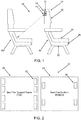
- the inventive concepts disclosed herein are generally directed to a seat sensor array 10 that is coupled to a seat assembly 12 in the passenger compartment of an aircraft or the like.
- the seat sensor array 10 includes three distinct types of sensors: (1) a passenger presence sensor 14 operable for determining if a passenger is present in or absent from a seat 16a; (2) a seat back position sensor 18 operable for determining if a seat back 20 of the seat 16a is in a reclined or upright position; and (3) a seat cushion engagement sensor 22 operable for determining if a seat cushion 24 of the seat 16a is dislodged or removed from the seat 16a.
- the passenger presence sensor 14 and the seat back position sensor 18 are disposed in a common housing 26 located in or around the seat back 20 of the seat 16a, while the seat cushion engagement sensor 22 is located in or around a seat pan support frame 28 supporting the seat cushion 24 of the seat 16a.
- the passenger presence sensor 14 is operable for determining if a passenger is present in or absent from a seat 16b that is adjacent to the seat 16a in which the passenger presence sensor 14 is located. It should be noted that other sensor placements are equally possible and all seats 16 are preferably, but not necessarily, comparably equipped.
- the passenger presence sensor 14 could be disposed in the bottom of the overhead compartment above a given seat 16.
- the passenger presence sensor 14 is an electromagnetic beam sensor, such as a visible or infrared (IR) beam sensor or the like.
- electromagnetic beam sensors consist of photoelectric sensors that emit light from an emitter, such as a light emitting diode (LED), a laser diode, or the like, and deliver it to a receiver, such as a photodiode or phototransistor.
- the electromagnetic beam sensor may be a through-beam sensor, with the emitter disposed in the housing 26 and the receiver disposed in a passenger receiving portion of the seat 16b.
- the electromagnetic beam sensor may be a retro-reflective sensor, with the emitter and receiver disposed in the housing 26 and a reflector disposed in the passenger receiving portion of the seat 16b.
- the electromagnetic beam sensor may be a diffusion sensor, with the emitter and receiver disposed in the housing 26 and the passenger receiving portion of the seat 16b and/or passenger acting as the reflector.
- the passenger presence sensor 14 typically measures the distance to the passenger receiving portion of the seat 16b without a passenger present and compares this measurement to the distance to the passenger when present. When a given threshold is exceeded, the passenger is deemed present.
- the seat back position sensor 18 is a simple electromagnetic position sensor or a gyroscopic (gyro) sensor.
- a gyro sensor is an angular rate sensor or angular velocity sensor that can sense angular motion and changes in orientation.
- Gyro sensors can sense angular velocity due to the Coriolis force that is applied to a vibrating element, for example. This motion produces a potential difference from which angular velocity is derived. The angular velocity is converted into an electrical signal output.
- the seat cushion engagement sensor 22 includes a plurality of contacts 30 coupled to the bottom of the seat cushion 24 that are electrically coupled to a plurality of contacts 32 coupled to the top of the seat pan support frame 28 when the seat cushion 24 is fully engaged with the seat pan support frame 28.
- contacts 30 and 32 may be disposed in the corners of the seat cushion 24 and seat pan support frame 28 such that it can be determined if one or more corners of the seat cushion 24 is/are dislodged from the seat pan support frame 28.
- Each of the contacts 30 and 32 may be a conductive hook-and-loop type fastener or the like.
- Each of the contacts 30 and 32 is in electrical communication with a processor such that breaks in the associated electrical circuits can be detected and assessed.
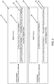
- FIG. 3 illustrates the seat cushion engagement sensor 22 is a closed circuit configuration, with the seat cushion 24 engaging the seat pan support frame 28 and the associated contacts 30 and 32 making electrical contact, and an open circuit configuration, with the seat cushion 24 disengaged from the seat pan support frame 28 and the associated contacts 30 and 32 failing to make electrical contact.
- a controller/processor 34 is in communication with the passenger presence sensor 14, the seat back position sensor 18, and the seat cushion engagement sensor 22 and operable for receiving passenger presence information from the passenger presence sensor 14 via a passenger presence sensor link, seat back position information from the seat back position sensor 18 via a seat back position sensor link, and seat cushion engagement information from the seat cushion engagement sensor 22 via a seat cushion engagement sensor link.
- This passenger presence information, seat back position information, and seat cushion engagement information is collected, analyzed, processed, and displayed to a crew member or the like in an easy to digest textual or graphical format.
- a text message or mobile app alert could be sent to the crew member indicating that a given passenger is (partially or wholly) present or absent, a given seat back is (partially or wholly) reclined or upright, and/or a given seat cushion is (partially or wholly) engaged or disengaged.
- This alert may incorporate an event alarm triggered by a predetermined condition and may take the form of a graphical representation of the passenger compartment of the aircraft including all seats and/or a given seat.
- the controller/processor 34 is optionally coupled to a wireless transmitter 36 that communicates the passenger presence information, seat back position information, and seat cushion engagement information to a crew alert device 38 like a management system, such as a crew management system (CMS), a mobile device used by a given crew member, etc.
- a management system such as a crew management system (CMS)
- CMS crew management system
- dedicated wired links may also be used equally.
- all sensor links can be part of a wireless local area network (WLAN) associated with the seat sensor array 10.
- WLAN wireless local area network
- a server when used, is a digital computer that, in terms of hardware architecture, generally includes a processor, input/output (I/O) interfaces, a network interface, a data store, and memory. It should be appreciated by those of ordinary skill in the art that a practical embodiment of the server may include additional components and suitably configured processing logic to support known or conventional operating features that are not described in detail herein.
- the components are communicatively coupled via a local interface.
- the local interface may be, for example but not limited to, one or more buses or other wired or wireless connections, as is known in the art.
- the local interface may have additional elements, which are omitted for simplicity, such as controllers, buffers (caches), drivers, repeaters, and receivers, among many others, to enable communications. Further, the local interface may include address, control, and/or data connections to enable appropriate communications among the aforementioned components.
- the controller/processor 34 is a hardware device for executing software instructions.
- the controller/processor 34 may be any custom made or commercially available processor, a central processing unit (CPU), an auxiliary processor among several processors associated with the server, a semiconductor-based microprocessor (in the form of a microchip or chip set), or generally any device for executing software instructions.
- the controller/processor 34 is configured to execute software stored within the memory, to communicate data to and from the memory, and to generally control operations of the server pursuant to the software instructions.
- the I/O interfaces may be used to receive user input from and/or for providing system output to one or more devices or components. User input may be provided via, for example, a keyboard, touch pad, and/or a mouse.
- I/O interfaces may include, for example, a serial port, a parallel port, a small computer system interface (SCSI), a serial ATA (SATA), a fibre channel, Infiniband, iSCSI, a PCI Express interface (PCI-x), an infrared (IR) interface, a radio frequency (RF) interface, and/or a universal serial bus (USB) interface.
- SCSI small computer system interface
- SATA serial ATA
- PCI-x PCI Express interface
- IR infrared
- RF radio frequency
- USB universal serial bus
- the network interface may be used to enable the server to communicate on a network, such as the Internet, a wide area network (WAN), a local area network (LAN), and the like, etc.
- the network interface may include, for example, an Ethernet card or adapter (e.g., 10BaseT, Fast Ethernet, Gigabit Ethernet, 10GbE) or a wireless local area network (WLAN) card or adapter (e.g., 802.11a/b/g/n).
- the network interface may include address, control, and/or data connections to enable appropriate communications on the network.
- a data store may be used to store data.
- the data store may include any of volatile memory elements (e.g., random access memory (RAM, such as DRAM, SRAM, SDRAM, and the like)), nonvolatile memory elements (e.g., ROM, hard drive, tape, CDROM, and the like), and combinations thereof.
- the data store may incorporate electronic, magnetic, optical, and/or other types of storage media.
- the data store may be located internal to the server such as, for example, an internal hard drive connected to the local interface in the server.
- the data store may be located external to the server such as, for example, an external hard drive connected to the I/O interfaces (e.g., SCSI or USB connection).
- the data store may be connected to the server through a network, such as, for example, a network attached file server.
- the memory may include any of volatile memory elements (e.g., random access memory (RAM, such as DRAM, SRAM, SDRAM, etc.)), nonvolatile memory elements (e.g., ROM, hard drive, tape, CDROM, etc.), and combinations thereof. Moreover, the memory may incorporate electronic, magnetic, optical, and/or other types of storage media. Note that the memory may have a distributed architecture, where various components are situated remotely from one another, but can be accessed by the controller/processor 34.
- the software in memory may include one or more software programs, each of which includes an ordered listing of executable instructions for implementing logical functions.
- the software in the memory includes a suitable operating system (O/S) and one or more programs.
- O/S operating system
- the operating system essentially controls the execution of other computer programs, such as the one or more programs, and provides scheduling, input-output control, file and data management, memory management, and communication control and related services.
- the one or more programs may be configured to implement the various processes, algorithms, methods, techniques, etc. described herein.
- the mobile device can be a digital device that, in terms of hardware architecture, generally includes a processor, input/output (I/O) interfaces, a radio, a data store, and memory. It should be appreciated by those of ordinary skill in the art that a practical embodiment may include additional components and suitably configured processing logic to support known or conventional operating features that are not described in detail herein.
- the components are communicatively coupled via a local interface.
- the local interface can be, for example but not limited to, one or more buses or other wired or wireless connections, as is known in the art.
- the local interface can have additional elements, which are omitted for simplicity, such as controllers, buffers (caches), drivers, repeaters, and receivers, among many others, to enable communications. Further, the local interface may include address, control, and/or data connections to enable appropriate communications among the aforementioned components.
- the processor is a hardware device for executing software instructions.
- the processor can be any custom made or commercially available processor, a central processing unit (CPU), an auxiliary processor among several processors associated with the memory, a semiconductor-based microprocessor (in the form of a microchip or chip set), or generally any device for executing software instructions.
- the processor is configured to execute software stored within the memory, to communicate data to and from the memory, and to generally control operations of the mobile device pursuant to the software instructions.
- the processor may include a mobile optimized processor such as optimized for power consumption and mobile applications.
- the I/O interfaces can be used to receive user input from and/or for providing system output.
- User input can be provided via, for example, a keypad, a touch screen, a scroll ball, a scroll bar, buttons, bar code scanner, and the like.
- System output can be provided via a display device such as a liquid crystal display (LCD), touch screen, and the like.
- the I/O interfaces can also include, for example, a serial port, a parallel port, a small computer system interface (SCSI), an infrared (IR) interface, a radio frequency (RF) interface, a universal serial bus (USB) interface, and the like.
- the I/O interfaces can include a graphical user interface (GUI) that enables a user to interact with the memory. Additionally, the I/O interfaces may further include an imaging device, i.e. camera, video camera, etc.
- an imaging device i.e. camera, video camera, etc.
- the radio enables wireless communication to an external access device or network.
- Any number of suitable wireless data communication protocols, techniques, or methodologies can be supported by the radio, including, without limitation: RF; IrDA (infrared); Bluetooth; ZigBee (and other variants of the IEEE 802.15 protocol); IEEE 802.11 (any variation); IEEE 802.16 (WiMAX or any other variation); Direct Sequence Spread Spectrum; Frequency Hopping Spread Spectrum; Long Term Evolution (LTE); cellular/wireless/cordless telecommunication protocols (e.g.
- the data store may be used to store data.
- the data store may include any of volatile memory elements (e.g., random access memory (RAM, such as DRAM, SRAM, SDRAM, and the like)), nonvolatile memory elements (e.g., ROM, hard drive, tape, CDROM, and the like), and combinations thereof.
- the data store may incorporate electronic, magnetic, optical, and/or other types of storage media.
- the memory may include any of volatile memory elements (e.g., random access memory (RAM, such as DRAM, SRAM, SDRAM, etc.)), nonvolatile memory elements (e.g., ROM, hard drive, etc.), and combinations thereof. Moreover, the memory may incorporate electronic, magnetic, optical, and/or other types of storage media. Note that the memory may have a distributed architecture, where various components are situated remotely from one another, but can be accessed by the processor.
- the software in memory can include one or more software programs, each of which includes an ordered listing of executable instructions for implementing logical functions.
- the software in the memory includes a suitable operating system (O/S) and programs.
- O/S operating system
- the operating system essentially controls the execution of other computer programs, and provides scheduling, input-output control, file and data management, memory management, and communication control and related services.
- the programs may include various applications, add-ons, etc. configured to provide end user functionality with the mobile device.
- the end user typically uses one or more of the programs along with a network.
- the programs can include an application or "app" which provides various functionality in communication with the seat sensor array 10.
- all housings and memories described herein may be hardened such that components and data may be preserved in the event of a catastrophic occurrence or the like.
- the seat sensor array 10 described herein aides in the onboarding process and allows a flight crew to verify that an aircraft is secured and ready for takeoff or landing, for example. Typically, such identification is performed by visual inspection by the flight crew. This is a labor intensive process and does not ensure that a passenger does not leave his or her seat after the visual inspection is performed, for example. Further, the seat sensor array 10 described herein allows the flight crew to verify that each and every seat back is in an upright position before takeoff or landing, for example. Again, such verification is typically performed by visual inspection by the flight crew. This is a labor intensive process and does not ensure that a passenger does move leave his or her seat back after the visual inspection is performed, for example.
- the seat sensor array 10 described herein allows the flight crew to determine if a seat cushion is dislodged or removed. Such a dislodged seat cushion could indicate the presence of a prohibited object beneath the seat cushion or prevent the seat cushion from functioning as intended during an emergency. Again, such determination is typically performed by visual inspection by the flight crew. This is a labor intensive process and does not ensure that a passenger does dislodge his or her seat cushion after the visual inspection is performed, for example.
Landscapes
- Engineering & Computer Science (AREA)
- Aviation & Aerospace Engineering (AREA)
- Transportation (AREA)
- Mechanical Engineering (AREA)
- Seats For Vehicles (AREA)
Abstract
Description
- In air travel and the like, it is important to identify the presence or absence of a passenger in or from each seat in the passenger compartment. This aides in the onboarding process and allows a flight crew to verify that an aircraft is secured and ready for takeoff or landing, for example. Typically, such identification is performed by visual inspection by the flight crew. This is a labor intensive process and does not ensure that a passenger does not leave his or her seat after the visual inspection is performed, for example.
- In air travel and the like, for safety reasons, it is also important to verify that each and every seat back is in an upright position before takeoff or landing, for example. Again, such verification is typically performed by visual inspection by the flight crew. This is a labor intensive process and does not ensure that a passenger does move leave his or her seat back after the visual inspection is performed, for example.
- In air travel and the like, for safety reasons, it is further important to determine if a seat cushion is dislodged or removed. Such a dislodged seat cushion could indicate the presence of a prohibited object beneath the seat cushion or prevent the seat cushion from functioning as intended during an emergency. Again, such determination is typically performed by visual inspection by the flight crew. This is a labor intensive process and does not ensure that a passenger does dislodge his or her seat cushion after the visual inspection is performed, for example.
- Although there are existing systems and methods available for individually identifying the presence or absence of a passenger in or from a given seat in the passenger compartment, verifying that a given seat back is in an upright position, and determining if a given seat cushion is dislodged or removed, what are still needed in the art are systems or methods for performing and coordinating more than one of these functions simultaneously.
- In one aspect, the inventive concepts disclosed herein are directed to a seat sensor array for use in a transportation vehicle such as an aircraft, including: a passenger presence sensor operable for determining if a passenger is present in or absent from a seat; a seat back position sensor operable for determining if a seat back of the seat is in a reclined or upright position; and a controller in communication with the passenger presence sensor and the seat back position sensor operable for receiving passenger presence information from the passenger presence sensor and seat back position information from the seat back position sensor and communicating this passenger presence information and seat back position information to a crew member. The passenger presence sensor may be an object sensor, which may be positioned in proximity to a seat and operable for sensing a position of a reference point near or on the seat and a position of an object near or on the seat. In another aspect, the seat sensor array further includes a seat cushion engagement sensor operable for determining if a seat cushion of the seat is dislodged or removed from the seat. Preferably, the controller is also in communication with the seat cushion engagement sensor and is also operable for receiving seat cushion engagement information from the seat cushion engagement sensor and communicating this seat cushion engagement information to the crew member. The seat cushion engagement sensor may include an electrical circuit that is broken when the seat cushion of the seat is dislodged or removed from the seat. The passenger presence sensor may be an electromagnetic beam sensor. In a till further embodiment, the electromagnetic beam sensor is coupled to one of a seat back of another seat and a bulkhead disposed in front of the seat and projects an electromagnetic beam into a passenger receiving portion of the seat. The seat back position sensor may be a gyroscopic sensor coupled to the seat back of the seat. The controller may be coupled to a wireless transmitter that communicates the passenger presence information and seat back position information to one of a management system and a mobile device used by the crew member. The controller may also be coupled to a wireless transmitter that communicates the passenger presence information, seat back position information, and seat cushion engagement information to one of a management system and a mobile device used by the crew member.
- In another aspect, the inventive concepts disclosed herein are directed to a seat assembly for use in a transportation vehicle such as an aircraft, including: a seat including a seat back and a seat cushion; a passenger presence sensor operable for determining if a passenger is present in or absent from the seat; a seat back position sensor operable for determining if the seat back of the seat is in a reclined or upright position; and a controller in communication with the passenger presence sensor and the seat back position sensor operable for receiving passenger presence information from the passenger presence sensor and seat back position information from the seat back position sensor and communicating this passenger presence information and seat back position information to a crew member. The seat assembly may further include a seat cushion engagement sensor operable for determining if the seat cushion of the seat is dislodged or removed from the seat. The controller is also in communication with the seat cushion engagement sensor and is also operable for receiving seat cushion engagement information from the seat cushion engagement sensor and communicating this seat cushion engagement information to the crew member. The seat cushion engagement sensor may include an electrical circuit that is broken when the seat cushion of the seat is dislodged or removed from the seat. The passenger presence sensor may be an electromagnetic beam sensor which may be coupled to one of a seat back of another seat and a bulkhead disposed in front of the seat and projects an electromagnetic beam into a passenger receiving portion of the seat. The seat back position sensor may be a gyroscopic sensor coupled to the seat back of the seat. The controller may be coupled to a wireless transmitter that communicates the passenger presence information and seat back position information to one of a management system and a mobile device used by the crew member. The controller may be coupled to a wireless transmitter that communicates the passenger presence information, seat back position information, and seat cushion engagement information to one of a management system and a mobile device used by the crew member.
- In a further aspect, the inventive concepts disclosed herein are directed to a controller for a seat sensor array for use in a transportation vehicle such as an aircraft, including: a passenger presence sensor link to a passenger presence sensor operable for determining if a passenger is present in or absent from a seat; a seat back position sensor link to a seat back position sensor operable for determining if a seat back of the seat is in a reclined or upright position; and a communication link operable for receiving passenger presence information from the passenger presence sensor link and seat back position information from the seat back position sensor link and communicating this passenger presence information and seat back position information to a crew member. The controller further may include a seat cushion engagement sensor link to a seat cushion engagement sensor operable for determining if a seat cushion of the seat is dislodged or removed from the seat, wherein the communication link may also be operable for receiving seat cushion engagement information from the seat cushion engagement sensor link and communicating this seat cushion engagement information to the crew member. In a further aspect, the controller may include a wireless link that communicates information to one of a management system and a mobile device used by the crew member.
- Embodiments of the inventive concepts can include one or more or any combination of the above aspects, features, and configurations.
- Implementations of the inventive concepts disclosed herein may be better understood when consideration is given to the following detailed description thereof. Such description makes reference to the included drawings, which are not necessarily to scale, and in which some features may be exaggerated and some features may be omitted or may be represented schematically in the interest of clarity. Like reference numerals in the drawings may represent and refer to the same or similar element, feature, or function. In the drawings:
-
FIG. 1 is a planar view of one exemplary embodiment of the seat sensor array and seat assembly according to the present invention; -
FIG. 2 is a planar view of one exemplary embodiment of the seat cushion engagement sensor assembly according to the present invention; -
FIG. 3 is a schematic view of one exemplary embodiment of the seat cushion engagement sensor assembly according to the present invention in both closed circuit (seat cushion present/engaged) and open circuit (seat cushion absent/disengaged) configurations; and -
FIG. 4 is a schematic view of one exemplary embodiment of the seat sensor controller according to the present invention. - The inventive concepts are described hereinafter with reference to the accompanying drawings in which exemplary embodiments are shown. However, the inventive concepts may be embodied in many different forms and are limited by the appended claims. They should not be construed as limited further to the representative embodiments set forth herein.
- Referring specifically to
FIG. 1 , the inventive concepts disclosed herein are generally directed to aseat sensor array 10 that is coupled to aseat assembly 12 in the passenger compartment of an aircraft or the like. Theseat sensor array 10 includes three distinct types of sensors: (1) apassenger presence sensor 14 operable for determining if a passenger is present in or absent from aseat 16a; (2) a seatback position sensor 18 operable for determining if aseat back 20 of theseat 16a is in a reclined or upright position; and (3) a seatcushion engagement sensor 22 operable for determining if aseat cushion 24 of theseat 16a is dislodged or removed from theseat 16a. Optionally, thepassenger presence sensor 14 and the seatback position sensor 18 are disposed in a common housing 26 located in or around theseat back 20 of theseat 16a, while the seatcushion engagement sensor 22 is located in or around a seatpan support frame 28 supporting theseat cushion 24 of theseat 16a. In this configuration, thepassenger presence sensor 14 is operable for determining if a passenger is present in or absent from aseat 16b that is adjacent to theseat 16a in which thepassenger presence sensor 14 is located. It should be noted that other sensor placements are equally possible and all seats 16 are preferably, but not necessarily, comparably equipped. For example, thepassenger presence sensor 14 could be disposed in the bottom of the overhead compartment above a given seat 16. - In an exemplary embodiment, the
passenger presence sensor 14 is an electromagnetic beam sensor, such as a visible or infrared (IR) beam sensor or the like. Such electromagnetic beam sensors consist of photoelectric sensors that emit light from an emitter, such as a light emitting diode (LED), a laser diode, or the like, and deliver it to a receiver, such as a photodiode or phototransistor. The electromagnetic beam sensor may be a through-beam sensor, with the emitter disposed in the housing 26 and the receiver disposed in a passenger receiving portion of theseat 16b. Alternatively, the electromagnetic beam sensor may be a retro-reflective sensor, with the emitter and receiver disposed in the housing 26 and a reflector disposed in the passenger receiving portion of theseat 16b. Alternatively, and most preferably, the electromagnetic beam sensor may be a diffusion sensor, with the emitter and receiver disposed in the housing 26 and the passenger receiving portion of theseat 16b and/or passenger acting as the reflector. In general, thepassenger presence sensor 14 typically measures the distance to the passenger receiving portion of theseat 16b without a passenger present and compares this measurement to the distance to the passenger when present. When a given threshold is exceeded, the passenger is deemed present. - In an exemplary embodiment, the seat
back position sensor 18 is a simple electromagnetic position sensor or a gyroscopic (gyro) sensor. A gyro sensor is an angular rate sensor or angular velocity sensor that can sense angular motion and changes in orientation. Gyro sensors can sense angular velocity due to the Coriolis force that is applied to a vibrating element, for example. This motion produces a potential difference from which angular velocity is derived. The angular velocity is converted into an electrical signal output. - Referring specifically to
FIG. 2 , in an exemplary embodiment, the seatcushion engagement sensor 22 includes a plurality ofcontacts 30 coupled to the bottom of theseat cushion 24 that are electrically coupled to a plurality ofcontacts 32 coupled to the top of the seatpan support frame 28 when theseat cushion 24 is fully engaged with the seatpan support frame 28. For example,contacts seat cushion 24 and seatpan support frame 28 such that it can be determined if one or more corners of theseat cushion 24 is/are dislodged from the seatpan support frame 28. Each of thecontacts contacts -
FIG. 3 illustrates the seatcushion engagement sensor 22 is a closed circuit configuration, with theseat cushion 24 engaging the seatpan support frame 28 and the associatedcontacts seat cushion 24 disengaged from the seatpan support frame 28 and the associatedcontacts - Referring specifically to
FIG. 4 , in an exemplary embodiment, a controller/processor 34 is in communication with thepassenger presence sensor 14, the seat backposition sensor 18, and the seatcushion engagement sensor 22 and operable for receiving passenger presence information from thepassenger presence sensor 14 via a passenger presence sensor link, seat back position information from the seat backposition sensor 18 via a seat back position sensor link, and seat cushion engagement information from the seatcushion engagement sensor 22 via a seat cushion engagement sensor link. This passenger presence information, seat back position information, and seat cushion engagement information is collected, analyzed, processed, and displayed to a crew member or the like in an easy to digest textual or graphical format. For example, a text message or mobile app alert could be sent to the crew member indicating that a given passenger is (partially or wholly) present or absent, a given seat back is (partially or wholly) reclined or upright, and/or a given seat cushion is (partially or wholly) engaged or disengaged. This alert may incorporate an event alarm triggered by a predetermined condition and may take the form of a graphical representation of the passenger compartment of the aircraft including all seats and/or a given seat. - Accordingly, the controller/
processor 34 is optionally coupled to awireless transmitter 36 that communicates the passenger presence information, seat back position information, and seat cushion engagement information to acrew alert device 38 like a management system, such as a crew management system (CMS), a mobile device used by a given crew member, etc. It will be readily apparent to those of ordinary skill in the art that dedicated wired links may also be used equally. In this respect, all sensor links can be part of a wireless local area network (WLAN) associated with theseat sensor array 10. - A server, when used, is a digital computer that, in terms of hardware architecture, generally includes a processor, input/output (I/O) interfaces, a network interface, a data store, and memory. It should be appreciated by those of ordinary skill in the art that a practical embodiment of the server may include additional components and suitably configured processing logic to support known or conventional operating features that are not described in detail herein. The components are communicatively coupled via a local interface. The local interface may be, for example but not limited to, one or more buses or other wired or wireless connections, as is known in the art. The local interface may have additional elements, which are omitted for simplicity, such as controllers, buffers (caches), drivers, repeaters, and receivers, among many others, to enable communications. Further, the local interface may include address, control, and/or data connections to enable appropriate communications among the aforementioned components.
- The controller/
processor 34 is a hardware device for executing software instructions. The controller/processor 34 may be any custom made or commercially available processor, a central processing unit (CPU), an auxiliary processor among several processors associated with the server, a semiconductor-based microprocessor (in the form of a microchip or chip set), or generally any device for executing software instructions. When the server is in operation, the controller/processor 34 is configured to execute software stored within the memory, to communicate data to and from the memory, and to generally control operations of the server pursuant to the software instructions. The I/O interfaces may be used to receive user input from and/or for providing system output to one or more devices or components. User input may be provided via, for example, a keyboard, touch pad, and/or a mouse. System output may be provided via a display device and a printer (not shown). I/O interfaces may include, for example, a serial port, a parallel port, a small computer system interface (SCSI), a serial ATA (SATA), a fibre channel, Infiniband, iSCSI, a PCI Express interface (PCI-x), an infrared (IR) interface, a radio frequency (RF) interface, and/or a universal serial bus (USB) interface. - The network interface may be used to enable the server to communicate on a network, such as the Internet, a wide area network (WAN), a local area network (LAN), and the like, etc. The network interface may include, for example, an Ethernet card or adapter (e.g., 10BaseT, Fast Ethernet, Gigabit Ethernet, 10GbE) or a wireless local area network (WLAN) card or adapter (e.g., 802.11a/b/g/n). The network interface may include address, control, and/or data connections to enable appropriate communications on the network. A data store may be used to store data. The data store may include any of volatile memory elements (e.g., random access memory (RAM, such as DRAM, SRAM, SDRAM, and the like)), nonvolatile memory elements (e.g., ROM, hard drive, tape, CDROM, and the like), and combinations thereof. Moreover, the data store may incorporate electronic, magnetic, optical, and/or other types of storage media. In one example, the data store may be located internal to the server such as, for example, an internal hard drive connected to the local interface in the server. Additionally, in another embodiment, the data store may be located external to the server such as, for example, an external hard drive connected to the I/O interfaces (e.g., SCSI or USB connection). In a further embodiment, the data store may be connected to the server through a network, such as, for example, a network attached file server.
- The memory may include any of volatile memory elements (e.g., random access memory (RAM, such as DRAM, SRAM, SDRAM, etc.)), nonvolatile memory elements (e.g., ROM, hard drive, tape, CDROM, etc.), and combinations thereof. Moreover, the memory may incorporate electronic, magnetic, optical, and/or other types of storage media. Note that the memory may have a distributed architecture, where various components are situated remotely from one another, but can be accessed by the controller/
processor 34. The software in memory may include one or more software programs, each of which includes an ordered listing of executable instructions for implementing logical functions. The software in the memory includes a suitable operating system (O/S) and one or more programs. The operating system essentially controls the execution of other computer programs, such as the one or more programs, and provides scheduling, input-output control, file and data management, memory management, and communication control and related services. The one or more programs may be configured to implement the various processes, algorithms, methods, techniques, etc. described herein. - The mobile device can be a digital device that, in terms of hardware architecture, generally includes a processor, input/output (I/O) interfaces, a radio, a data store, and memory. It should be appreciated by those of ordinary skill in the art that a practical embodiment may include additional components and suitably configured processing logic to support known or conventional operating features that are not described in detail herein. The components are communicatively coupled via a local interface. The local interface can be, for example but not limited to, one or more buses or other wired or wireless connections, as is known in the art. The local interface can have additional elements, which are omitted for simplicity, such as controllers, buffers (caches), drivers, repeaters, and receivers, among many others, to enable communications. Further, the local interface may include address, control, and/or data connections to enable appropriate communications among the aforementioned components.
- The processor is a hardware device for executing software instructions. The processor can be any custom made or commercially available processor, a central processing unit (CPU), an auxiliary processor among several processors associated with the memory, a semiconductor-based microprocessor (in the form of a microchip or chip set), or generally any device for executing software instructions. When the mobile device is in operation, the processor is configured to execute software stored within the memory, to communicate data to and from the memory, and to generally control operations of the mobile device pursuant to the software instructions. In an exemplary embodiment, the processor may include a mobile optimized processor such as optimized for power consumption and mobile applications. The I/O interfaces can be used to receive user input from and/or for providing system output. User input can be provided via, for example, a keypad, a touch screen, a scroll ball, a scroll bar, buttons, bar code scanner, and the like. System output can be provided via a display device such as a liquid crystal display (LCD), touch screen, and the like. The I/O interfaces can also include, for example, a serial port, a parallel port, a small computer system interface (SCSI), an infrared (IR) interface, a radio frequency (RF) interface, a universal serial bus (USB) interface, and the like. The I/O interfaces can include a graphical user interface (GUI) that enables a user to interact with the memory. Additionally, the I/O interfaces may further include an imaging device, i.e. camera, video camera, etc.
- The radio enables wireless communication to an external access device or network. Any number of suitable wireless data communication protocols, techniques, or methodologies can be supported by the radio, including, without limitation: RF; IrDA (infrared); Bluetooth; ZigBee (and other variants of the IEEE 802.15 protocol); IEEE 802.11 (any variation); IEEE 802.16 (WiMAX or any other variation); Direct Sequence Spread Spectrum; Frequency Hopping Spread Spectrum; Long Term Evolution (LTE); cellular/wireless/cordless telecommunication protocols (e.g. 3G/4G, etc.); Land Mobile Radio (LMR); Digital Mobile Radio (DMR); Terrestrial Trunked Radio (TETRA); Project 25 (P25); wireless home network communication protocols; paging network protocols; magnetic induction; satellite data communication protocols; wireless hospital or health care facility network protocols such as those operating in the WMTS bands; GPRS; proprietary wireless data communication protocols such as variants of Wireless USB; and any other protocols for wireless communication. The data store may be used to store data. The data store may include any of volatile memory elements (e.g., random access memory (RAM, such as DRAM, SRAM, SDRAM, and the like)), nonvolatile memory elements (e.g., ROM, hard drive, tape, CDROM, and the like), and combinations thereof. Moreover, the data store may incorporate electronic, magnetic, optical, and/or other types of storage media.
- The memory may include any of volatile memory elements (e.g., random access memory (RAM, such as DRAM, SRAM, SDRAM, etc.)), nonvolatile memory elements (e.g., ROM, hard drive, etc.), and combinations thereof. Moreover, the memory may incorporate electronic, magnetic, optical, and/or other types of storage media. Note that the memory may have a distributed architecture, where various components are situated remotely from one another, but can be accessed by the processor. The software in memory can include one or more software programs, each of which includes an ordered listing of executable instructions for implementing logical functions. The software in the memory includes a suitable operating system (O/S) and programs. The operating system essentially controls the execution of other computer programs, and provides scheduling, input-output control, file and data management, memory management, and communication control and related services. The programs may include various applications, add-ons, etc. configured to provide end user functionality with the mobile device. In a typical example, the end user typically uses one or more of the programs along with a network. The programs can include an application or "app" which provides various functionality in communication with the
seat sensor array 10. - In general, all housings and memories described herein may be hardened such that components and data may be preserved in the event of a catastrophic occurrence or the like.
- Again, the
seat sensor array 10 described herein aides in the onboarding process and allows a flight crew to verify that an aircraft is secured and ready for takeoff or landing, for example. Typically, such identification is performed by visual inspection by the flight crew. This is a labor intensive process and does not ensure that a passenger does not leave his or her seat after the visual inspection is performed, for example. Further, theseat sensor array 10 described herein allows the flight crew to verify that each and every seat back is in an upright position before takeoff or landing, for example. Again, such verification is typically performed by visual inspection by the flight crew. This is a labor intensive process and does not ensure that a passenger does move leave his or her seat back after the visual inspection is performed, for example. Further, theseat sensor array 10 described herein allows the flight crew to determine if a seat cushion is dislodged or removed. Such a dislodged seat cushion could indicate the presence of a prohibited object beneath the seat cushion or prevent the seat cushion from functioning as intended during an emergency. Again, such determination is typically performed by visual inspection by the flight crew. This is a labor intensive process and does not ensure that a passenger does dislodge his or her seat cushion after the visual inspection is performed, for example. - The foregoing description provides embodiments of the invention by way of example only. It is envisioned that other embodiments may perform similar functions and/or achieve similar results.
Claims (15)
- A seat sensor array (10) for use in a transportation vehicle such as an aircraft, comprising:a passenger presence sensor (14) operable for determining if a passenger is present in or absent from a seat (16a);a seat back position sensor (18) operable for determining if a seat back (20) of the seat (16a) is in a reclined or upright position; anda controller (34) in communication with the passenger presence sensor (14) and the seat back position sensor (18) operable for receiving passenger presence information from the passenger presence sensor (14) and seat back position information from the seat back position sensor (18), characterized in that the controller (34) is further configured to determine passenger presence in or absence from the seat (16a) based on a comparison of a measured distance to a passenger receiving portion of an unoccupied seat to a measured distance to a passenger present in the seat (16a), wherein when a given threshold is exceeded a passenger is deemed present in the seat (16a), and the controller (34) further configured to communicate the passenger presence information to a crew member device (38).
- The seat sensor array (10) according to claim 1, further comprising a seat cushion engagement sensor (22) operable for determining if a seat cushion (24) of the seat (16a) is dislodged or removed from the seat.
- The seat sensor array (10) according to claim 2, wherein the controller (34) is also in communication with the seat cushion engagement sensor (22) and is also operable for receiving seat cushion engagement information from the seat cushion engagement sensor (22) and communicating this seat cushion engagement information to the crew member device (38).
- The seat sensor array (10) according to claim 2 or 3, wherein the seat cushion engagement sensor (22) comprises an electrical circuit that is broken when the seat cushion (24) of the seat is dislodged or removed from the seat.
- The seat sensor array (10) according to one or more of claims 1-4, wherein the passenger presence sensor (14) comprises an electromagnetic beam sensor, wherein the electromagnetic beam sensor projects an electromagnetic beam toward the passenger receiving portion of the seat (16a).
- The sensor array (10) according to one or more of claims 1-5, wherein the seat back position sensor (18) comprises a gyroscopic sensor coupled to the seat back (20) of the seat (16a).
- The sensor array (10) according to one or more of claim 6, wherein the controller (34) is coupled to a wireless transmitter that communicates the passenger presence information and seat back position information to one of a management system and a mobile device used by the crew member.
- The sensor array (10) according to one or more of claims 3-7, wherein the controller (34) is coupled to a wireless transmitter that communicates the passenger presence information, seat back position information, and seat cushion engagement information to one of a management system and a mobile device used by the crew member.
- A seat sensor array (10) for use in a transportation vehicle such as an aircraft, comprising:an object sensor (14) positioned in proximity to a seat (16a) operable for determining a position of a reference point near or on the seat (16a) and a position of an object near or on the seat (16a); anda controller (34) in communication with the object sensor (14) operable for receiving reference point and object location positional information, characterized in that the controller (34) is further operable for comparing the sensed position of the object and the sensed position of the reference point to determine a distance of the object from a reference point, determining a compliance status of the object based on the distance, and communicating to a crew member device (38) the compliance status of the object.
- The seat sensor array (10) according to claim 9, wherein the distance of the sensed object from the sensed reference point greater than a predetermined distance corresponds to a status of non-compliance of the object with a corresponding indication communicated to the crew member device (38).
- The seat sensor array (10) according to claim 9 or 10, wherein the distance of the sensed object from the sensed reference point less than or equal to a predetermined distance corresponds to a status of compliance of the object with a corresponding indication communicated to the crew member device (38).
- The seat sensor array (10) according to one or more of claims 9-11, wherein the object sensor (14) is an electromagnetic beam sensor.
- The seat sensor array (10) according to one or more of claims 9-12, wherein the electromagnetic beam sensor projects an electromagnetic beam toward a passenger receiving portion of the seat (16a).
- A seat assembly for use in a transportation vehicle such as an aircraft, including:a seat including a seat back and a seat cushion, anda seat sensor array according to one or more of the claims 1-14.
- A Controller for a seat sensor array for use in a transportation vehicle such as an aircraft, including: a passenger presence sensor (14) link to a passenger presence sensor (18) operable for determining if a passenger is present in or absent from a seat; a seat back position sensor link to a seat back position sensor (14) operable for determining if a seat back of the seat (16a) is in a reclined or upright position; and a communication link operable for receiving passenger presence information from the passenger presence sensor link and seat back position information from the seat back position sensor link and communicating this passenger presence information and seat back position information to a crew member device (38).
Applications Claiming Priority (1)
| Application Number | Priority Date | Filing Date | Title |
|---|---|---|---|
| US15/938,438 US10479524B2 (en) | 2018-03-28 | 2018-03-28 | Seat sensor array and controller and seat assembly incorporating same |
Publications (2)
| Publication Number | Publication Date |
|---|---|
| EP3546360A1 true EP3546360A1 (en) | 2019-10-02 |
| EP3546360B1 EP3546360B1 (en) | 2022-07-13 |
Family
ID=66001027
Family Applications (1)
| Application Number | Title | Priority Date | Filing Date |
|---|---|---|---|
| EP19165851.7A Active EP3546360B1 (en) | 2018-03-28 | 2019-03-28 | Seat sensor array and controller and seat assembly incorporating same |
Country Status (3)
| Country | Link |
|---|---|
| US (1) | US10479524B2 (en) |
| EP (1) | EP3546360B1 (en) |
| CN (1) | CN110316383B (en) |
Families Citing this family (6)
| Publication number | Priority date | Publication date | Assignee | Title |
|---|---|---|---|---|
| JP7157834B2 (en) * | 2021-01-29 | 2022-10-20 | 本田技研工業株式会社 | vehicle seat |
| JP7242723B2 (en) * | 2021-01-29 | 2023-03-20 | 本田技研工業株式会社 | vehicle seat |
| EP4063186B1 (en) | 2021-03-25 | 2024-03-13 | Goodrich Lighting Systems GmbH & Co. KG | Aircraft passenger service unit |
| CN114056576A (en) * | 2021-09-30 | 2022-02-18 | 湖北航宇嘉泰飞机设备有限公司 | Intelligent monitoring system for aviation seat |
| CN115959014B (en) * | 2022-06-21 | 2025-10-24 | 李明 | An intelligent seat control system and an electric seat composed of the same |
| US12479595B2 (en) | 2023-10-11 | 2025-11-25 | B/E Aerospace, Inc. | Method to detect objects or obstacles using radio |
Citations (9)
| Publication number | Priority date | Publication date | Assignee | Title |
|---|---|---|---|---|
| US20070035114A1 (en) * | 1992-05-05 | 2007-02-15 | Automotive Technologies International, Inc. | Device and Method for Deploying a Vehicular Occupant Protection System |
| DE102006030193A1 (en) * | 2006-06-30 | 2008-01-03 | Airbus Deutschland Gmbh | System for determining aircraft seat state has seat monitoring device that provides information about state of seat with sensor element for measuring physical data; device determines seat state information from physical data |
| DE102007055091A1 (en) * | 2007-11-16 | 2009-05-20 | Airbus Deutschland Gmbh | Seat arrangement in an aircraft |
| WO2009062974A1 (en) * | 2007-11-16 | 2009-05-22 | Eads Deutschland Gmbh | Seat comprising a seat element, seat arrangement and method for monitoring a seat |
| US8094041B2 (en) * | 2008-03-31 | 2012-01-10 | The Boeing Company | Seat cushion retention and monitoring in an aircraft |
| GB2496452A (en) * | 2011-11-14 | 2013-05-15 | Almec Eas Ltd | Aircraft seat with position and condition sensors |
| EP2730479A1 (en) * | 2012-11-07 | 2014-05-14 | TrainFX Limited | Passenger occupancy identification system |
| EP2910471A1 (en) * | 2014-02-25 | 2015-08-26 | Astronics Advanced Electronic Systems Corp. | Apparatus and method to monitor the occupancy of seating |
| WO2017176748A1 (en) * | 2016-04-04 | 2017-10-12 | B/E Aerospace, Inc. | Aircraft passenger activity monitoring |
Family Cites Families (6)
| Publication number | Priority date | Publication date | Assignee | Title |
|---|---|---|---|---|
| KR20010034684A (en) * | 1999-01-27 | 2001-04-25 | 후루까와 준노스께 | Occupant detecting device |
| US7878586B2 (en) * | 2007-10-29 | 2011-02-01 | The Boeing Company | System and method for an anticipatory passenger cabin |
| US8274383B2 (en) * | 2008-03-31 | 2012-09-25 | The Boeing Company | Methods and systems for sensing activity using energy harvesting devices |
| CN103987574B (en) * | 2011-12-02 | 2015-11-25 | 康斯博格汽车股份有限公司 | For the locking mechanism of Foldable head restraint |
| US10167089B2 (en) * | 2015-11-23 | 2019-01-01 | At&T Mobility Ii Llc | Gateway for aircraft sensor data |
| US20170355282A1 (en) * | 2016-06-14 | 2017-12-14 | Lear Corporation | Seat position detection for seat assemblies |
-
2018
- 2018-03-28 US US15/938,438 patent/US10479524B2/en active Active
-
2019
- 2019-03-28 CN CN201910242059.4A patent/CN110316383B/en active Active
- 2019-03-28 EP EP19165851.7A patent/EP3546360B1/en active Active
Patent Citations (9)
| Publication number | Priority date | Publication date | Assignee | Title |
|---|---|---|---|---|
| US20070035114A1 (en) * | 1992-05-05 | 2007-02-15 | Automotive Technologies International, Inc. | Device and Method for Deploying a Vehicular Occupant Protection System |
| DE102006030193A1 (en) * | 2006-06-30 | 2008-01-03 | Airbus Deutschland Gmbh | System for determining aircraft seat state has seat monitoring device that provides information about state of seat with sensor element for measuring physical data; device determines seat state information from physical data |
| DE102007055091A1 (en) * | 2007-11-16 | 2009-05-20 | Airbus Deutschland Gmbh | Seat arrangement in an aircraft |
| WO2009062974A1 (en) * | 2007-11-16 | 2009-05-22 | Eads Deutschland Gmbh | Seat comprising a seat element, seat arrangement and method for monitoring a seat |
| US8094041B2 (en) * | 2008-03-31 | 2012-01-10 | The Boeing Company | Seat cushion retention and monitoring in an aircraft |
| GB2496452A (en) * | 2011-11-14 | 2013-05-15 | Almec Eas Ltd | Aircraft seat with position and condition sensors |
| EP2730479A1 (en) * | 2012-11-07 | 2014-05-14 | TrainFX Limited | Passenger occupancy identification system |
| EP2910471A1 (en) * | 2014-02-25 | 2015-08-26 | Astronics Advanced Electronic Systems Corp. | Apparatus and method to monitor the occupancy of seating |
| WO2017176748A1 (en) * | 2016-04-04 | 2017-10-12 | B/E Aerospace, Inc. | Aircraft passenger activity monitoring |
Also Published As
| Publication number | Publication date |
|---|---|
| EP3546360B1 (en) | 2022-07-13 |
| US20190300198A1 (en) | 2019-10-03 |
| CN110316383A (en) | 2019-10-11 |
| US10479524B2 (en) | 2019-11-19 |
| CN110316383B (en) | 2023-03-24 |
Similar Documents
| Publication | Publication Date | Title |
|---|---|---|
| US10479524B2 (en) | Seat sensor array and controller and seat assembly incorporating same | |
| US10189406B1 (en) | Overhead storage bin utilization detection and display system | |
| US10755491B2 (en) | Electronic device for transmitting relay message to external vehicle and method thereof | |
| US9529356B2 (en) | Data management system of an aircraft | |
| US10881357B1 (en) | Systems and methods for monitoring the health of vehicle passengers using camera images | |
| KR20160101545A (en) | Method for providing service based on awareness and an electronic device thereof | |
| EP3466018B1 (en) | Systems and methods for averting unsanctioned access to on-board vehicle networks | |
| US10477155B2 (en) | Driving assistance method, driving assistance device, and recording medium recording program using same | |
| CN106155070B (en) | UAV takeoff control method and device, remote control terminal | |
| JP2017029219A (en) | In-flight passenger temperature monitoring system | |
| US9788150B2 (en) | Method for managing disaster and electronic device thereof | |
| WO2021175749A1 (en) | Method and system for triggering picture-taking of the interior of a vehicle based on a detection of a free-space gesture | |
| US11247698B2 (en) | Methods and systems for monitoring rear objects in a vehicle | |
| KR20180022005A (en) | Method for providing location information of a external device and electronic device thereof | |
| US9924028B2 (en) | Tamper resistant system for creating zones and manipulating computing devices | |
| US20150371458A1 (en) | Mobile computer peripheral | |
| US10530466B1 (en) | Wireless communication management apparatus, wireless communication management system, and wireless communication management method | |
| US20200053529A1 (en) | Waic interface device | |
| US11615686B2 (en) | Monitoring support apparatus and monitoring support method for supporting work of monitoring person who monitors plurality of subjects by sequentially visiting the plurality of subjects | |
| KR20130069100A (en) | Flight management system, flight manegement apparatus and the method for controlling the same | |
| CA3042662C (en) | System and method of determining a seat back status of a passenger seat in a vehicle | |
| US20260027869A1 (en) | Information processing method | |
| US20240081661A1 (en) | Health evaluation system, health evaluation method, and storage medium storing health evaluation program | |
| EP3771237B1 (en) | Wireless communication management apparatus, wireless communication management system, and wireless communication management method | |
| US20230096735A1 (en) | Electromagnetic radiation detection safety seat |
Legal Events
| Date | Code | Title | Description |
|---|---|---|---|
| PUAI | Public reference made under article 153(3) epc to a published international application that has entered the european phase |
Free format text: ORIGINAL CODE: 0009012 |
|
| STAA | Information on the status of an ep patent application or granted ep patent |
Free format text: STATUS: THE APPLICATION HAS BEEN PUBLISHED |
|
| AK | Designated contracting states |
Kind code of ref document: A1 Designated state(s): AL AT BE BG CH CY CZ DE DK EE ES FI FR GB GR HR HU IE IS IT LI LT LU LV MC MK MT NL NO PL PT RO RS SE SI SK SM TR |
|
| AX | Request for extension of the european patent |
Extension state: BA ME |
|
| STAA | Information on the status of an ep patent application or granted ep patent |
Free format text: STATUS: REQUEST FOR EXAMINATION WAS MADE |
|
| 17P | Request for examination filed |
Effective date: 20200331 |
|
| RBV | Designated contracting states (corrected) |
Designated state(s): AL AT BE BG CH CY CZ DE DK EE ES FI FR GB GR HR HU IE IS IT LI LT LU LV MC MK MT NL NO PL PT RO RS SE SI SK SM TR |
|
| STAA | Information on the status of an ep patent application or granted ep patent |
Free format text: STATUS: EXAMINATION IS IN PROGRESS |
|
| 17Q | First examination report despatched |
Effective date: 20200720 |
|
| GRAP | Despatch of communication of intention to grant a patent |
Free format text: ORIGINAL CODE: EPIDOSNIGR1 |
|
| STAA | Information on the status of an ep patent application or granted ep patent |
Free format text: STATUS: GRANT OF PATENT IS INTENDED |
|
| INTG | Intention to grant announced |
Effective date: 20220208 |
|
| GRAS | Grant fee paid |
Free format text: ORIGINAL CODE: EPIDOSNIGR3 |
|
| GRAA | (expected) grant |
Free format text: ORIGINAL CODE: 0009210 |
|
| STAA | Information on the status of an ep patent application or granted ep patent |
Free format text: STATUS: THE PATENT HAS BEEN GRANTED |
|
| AK | Designated contracting states |
Kind code of ref document: B1 Designated state(s): AL AT BE BG CH CY CZ DE DK EE ES FI FR GB GR HR HU IE IS IT LI LT LU LV MC MK MT NL NO PL PT RO RS SE SI SK SM TR |
|
| REG | Reference to a national code |
Ref country code: CH Ref legal event code: EP |
|
| REG | Reference to a national code |
Ref country code: DE Ref legal event code: R096 Ref document number: 602019016879 Country of ref document: DE |
|
| REG | Reference to a national code |
Ref country code: AT Ref legal event code: REF Ref document number: 1504164 Country of ref document: AT Kind code of ref document: T Effective date: 20220815 |
|
| REG | Reference to a national code |
Ref country code: IE Ref legal event code: FG4D |
|
| REG | Reference to a national code |
Ref country code: LT Ref legal event code: MG9D |
|
| REG | Reference to a national code |
Ref country code: NL Ref legal event code: MP Effective date: 20220713 |
|
| PG25 | Lapsed in a contracting state [announced via postgrant information from national office to epo] |
Ref country code: SE Free format text: LAPSE BECAUSE OF FAILURE TO SUBMIT A TRANSLATION OF THE DESCRIPTION OR TO PAY THE FEE WITHIN THE PRESCRIBED TIME-LIMIT Effective date: 20220713 Ref country code: RS Free format text: LAPSE BECAUSE OF FAILURE TO SUBMIT A TRANSLATION OF THE DESCRIPTION OR TO PAY THE FEE WITHIN THE PRESCRIBED TIME-LIMIT Effective date: 20220713 Ref country code: PT Free format text: LAPSE BECAUSE OF FAILURE TO SUBMIT A TRANSLATION OF THE DESCRIPTION OR TO PAY THE FEE WITHIN THE PRESCRIBED TIME-LIMIT Effective date: 20221114 Ref country code: NO Free format text: LAPSE BECAUSE OF FAILURE TO SUBMIT A TRANSLATION OF THE DESCRIPTION OR TO PAY THE FEE WITHIN THE PRESCRIBED TIME-LIMIT Effective date: 20221013 Ref country code: NL Free format text: LAPSE BECAUSE OF FAILURE TO SUBMIT A TRANSLATION OF THE DESCRIPTION OR TO PAY THE FEE WITHIN THE PRESCRIBED TIME-LIMIT Effective date: 20220713 Ref country code: LV Free format text: LAPSE BECAUSE OF FAILURE TO SUBMIT A TRANSLATION OF THE DESCRIPTION OR TO PAY THE FEE WITHIN THE PRESCRIBED TIME-LIMIT Effective date: 20220713 Ref country code: LT Free format text: LAPSE BECAUSE OF FAILURE TO SUBMIT A TRANSLATION OF THE DESCRIPTION OR TO PAY THE FEE WITHIN THE PRESCRIBED TIME-LIMIT Effective date: 20220713 Ref country code: FI Free format text: LAPSE BECAUSE OF FAILURE TO SUBMIT A TRANSLATION OF THE DESCRIPTION OR TO PAY THE FEE WITHIN THE PRESCRIBED TIME-LIMIT Effective date: 20220713 Ref country code: ES Free format text: LAPSE BECAUSE OF FAILURE TO SUBMIT A TRANSLATION OF THE DESCRIPTION OR TO PAY THE FEE WITHIN THE PRESCRIBED TIME-LIMIT Effective date: 20220713 |
|
| REG | Reference to a national code |
Ref country code: AT Ref legal event code: MK05 Ref document number: 1504164 Country of ref document: AT Kind code of ref document: T Effective date: 20220713 |
|
| PG25 | Lapsed in a contracting state [announced via postgrant information from national office to epo] |
Ref country code: PL Free format text: LAPSE BECAUSE OF FAILURE TO SUBMIT A TRANSLATION OF THE DESCRIPTION OR TO PAY THE FEE WITHIN THE PRESCRIBED TIME-LIMIT Effective date: 20220713 Ref country code: IS Free format text: LAPSE BECAUSE OF FAILURE TO SUBMIT A TRANSLATION OF THE DESCRIPTION OR TO PAY THE FEE WITHIN THE PRESCRIBED TIME-LIMIT Effective date: 20221113 Ref country code: HR Free format text: LAPSE BECAUSE OF FAILURE TO SUBMIT A TRANSLATION OF THE DESCRIPTION OR TO PAY THE FEE WITHIN THE PRESCRIBED TIME-LIMIT Effective date: 20220713 Ref country code: GR Free format text: LAPSE BECAUSE OF FAILURE TO SUBMIT A TRANSLATION OF THE DESCRIPTION OR TO PAY THE FEE WITHIN THE PRESCRIBED TIME-LIMIT Effective date: 20221014 |
|
| REG | Reference to a national code |
Ref country code: DE Ref legal event code: R097 Ref document number: 602019016879 Country of ref document: DE |
|
| PG25 | Lapsed in a contracting state [announced via postgrant information from national office to epo] |
Ref country code: SM Free format text: LAPSE BECAUSE OF FAILURE TO SUBMIT A TRANSLATION OF THE DESCRIPTION OR TO PAY THE FEE WITHIN THE PRESCRIBED TIME-LIMIT Effective date: 20220713 Ref country code: RO Free format text: LAPSE BECAUSE OF FAILURE TO SUBMIT A TRANSLATION OF THE DESCRIPTION OR TO PAY THE FEE WITHIN THE PRESCRIBED TIME-LIMIT Effective date: 20220713 Ref country code: DK Free format text: LAPSE BECAUSE OF FAILURE TO SUBMIT A TRANSLATION OF THE DESCRIPTION OR TO PAY THE FEE WITHIN THE PRESCRIBED TIME-LIMIT Effective date: 20220713 Ref country code: CZ Free format text: LAPSE BECAUSE OF FAILURE TO SUBMIT A TRANSLATION OF THE DESCRIPTION OR TO PAY THE FEE WITHIN THE PRESCRIBED TIME-LIMIT Effective date: 20220713 Ref country code: AT Free format text: LAPSE BECAUSE OF FAILURE TO SUBMIT A TRANSLATION OF THE DESCRIPTION OR TO PAY THE FEE WITHIN THE PRESCRIBED TIME-LIMIT Effective date: 20220713 |
|
| PLBE | No opposition filed within time limit |
Free format text: ORIGINAL CODE: 0009261 |
|
| STAA | Information on the status of an ep patent application or granted ep patent |
Free format text: STATUS: NO OPPOSITION FILED WITHIN TIME LIMIT |
|
| PG25 | Lapsed in a contracting state [announced via postgrant information from national office to epo] |
Ref country code: SK Free format text: LAPSE BECAUSE OF FAILURE TO SUBMIT A TRANSLATION OF THE DESCRIPTION OR TO PAY THE FEE WITHIN THE PRESCRIBED TIME-LIMIT Effective date: 20220713 Ref country code: EE Free format text: LAPSE BECAUSE OF FAILURE TO SUBMIT A TRANSLATION OF THE DESCRIPTION OR TO PAY THE FEE WITHIN THE PRESCRIBED TIME-LIMIT Effective date: 20220713 |
|
| 26N | No opposition filed |
Effective date: 20230414 |
|
| PG25 | Lapsed in a contracting state [announced via postgrant information from national office to epo] |
Ref country code: AL Free format text: LAPSE BECAUSE OF FAILURE TO SUBMIT A TRANSLATION OF THE DESCRIPTION OR TO PAY THE FEE WITHIN THE PRESCRIBED TIME-LIMIT Effective date: 20220713 |
|
| P01 | Opt-out of the competence of the unified patent court (upc) registered |
Effective date: 20230608 |
|
| PG25 | Lapsed in a contracting state [announced via postgrant information from national office to epo] |
Ref country code: SI Free format text: LAPSE BECAUSE OF FAILURE TO SUBMIT A TRANSLATION OF THE DESCRIPTION OR TO PAY THE FEE WITHIN THE PRESCRIBED TIME-LIMIT Effective date: 20220713 |
|
| PG25 | Lapsed in a contracting state [announced via postgrant information from national office to epo] |
Ref country code: MC Free format text: LAPSE BECAUSE OF FAILURE TO SUBMIT A TRANSLATION OF THE DESCRIPTION OR TO PAY THE FEE WITHIN THE PRESCRIBED TIME-LIMIT Effective date: 20220713 |
|
| REG | Reference to a national code |
Ref country code: CH Ref legal event code: PL |
|
| REG | Reference to a national code |
Ref country code: BE Ref legal event code: MM Effective date: 20230331 |
|
| PG25 | Lapsed in a contracting state [announced via postgrant information from national office to epo] |
Ref country code: LU Free format text: LAPSE BECAUSE OF NON-PAYMENT OF DUE FEES Effective date: 20230328 |
|
| REG | Reference to a national code |
Ref country code: IE Ref legal event code: MM4A |
|
| PG25 | Lapsed in a contracting state [announced via postgrant information from national office to epo] |
Ref country code: LI Free format text: LAPSE BECAUSE OF NON-PAYMENT OF DUE FEES Effective date: 20230331 Ref country code: IT Free format text: LAPSE BECAUSE OF FAILURE TO SUBMIT A TRANSLATION OF THE DESCRIPTION OR TO PAY THE FEE WITHIN THE PRESCRIBED TIME-LIMIT Effective date: 20220713 Ref country code: IE Free format text: LAPSE BECAUSE OF NON-PAYMENT OF DUE FEES Effective date: 20230328 Ref country code: CH Free format text: LAPSE BECAUSE OF NON-PAYMENT OF DUE FEES Effective date: 20230331 |
|
| PG25 | Lapsed in a contracting state [announced via postgrant information from national office to epo] |
Ref country code: BE Free format text: LAPSE BECAUSE OF NON-PAYMENT OF DUE FEES Effective date: 20230331 |
|
| PG25 | Lapsed in a contracting state [announced via postgrant information from national office to epo] |
Ref country code: BG Free format text: LAPSE BECAUSE OF FAILURE TO SUBMIT A TRANSLATION OF THE DESCRIPTION OR TO PAY THE FEE WITHIN THE PRESCRIBED TIME-LIMIT Effective date: 20220713 |
|
| PG25 | Lapsed in a contracting state [announced via postgrant information from national office to epo] |
Ref country code: BG Free format text: LAPSE BECAUSE OF FAILURE TO SUBMIT A TRANSLATION OF THE DESCRIPTION OR TO PAY THE FEE WITHIN THE PRESCRIBED TIME-LIMIT Effective date: 20220713 |
|
| PGFP | Annual fee paid to national office [announced via postgrant information from national office to epo] |
Ref country code: DE Payment date: 20250218 Year of fee payment: 7 |
|
| PGFP | Annual fee paid to national office [announced via postgrant information from national office to epo] |
Ref country code: FR Payment date: 20250218 Year of fee payment: 7 |
|
| PGFP | Annual fee paid to national office [announced via postgrant information from national office to epo] |
Ref country code: GB Payment date: 20250221 Year of fee payment: 7 |
|
| PG25 | Lapsed in a contracting state [announced via postgrant information from national office to epo] |
Ref country code: CY Free format text: LAPSE BECAUSE OF FAILURE TO SUBMIT A TRANSLATION OF THE DESCRIPTION OR TO PAY THE FEE WITHIN THE PRESCRIBED TIME-LIMIT; INVALID AB INITIO Effective date: 20190328 |
|
| PG25 | Lapsed in a contracting state [announced via postgrant information from national office to epo] |
Ref country code: HU Free format text: LAPSE BECAUSE OF FAILURE TO SUBMIT A TRANSLATION OF THE DESCRIPTION OR TO PAY THE FEE WITHIN THE PRESCRIBED TIME-LIMIT; INVALID AB INITIO Effective date: 20190328 |
|
| PG25 | Lapsed in a contracting state [announced via postgrant information from national office to epo] |
Ref country code: TR Free format text: LAPSE BECAUSE OF FAILURE TO SUBMIT A TRANSLATION OF THE DESCRIPTION OR TO PAY THE FEE WITHIN THE PRESCRIBED TIME-LIMIT Effective date: 20220713 |