EP3546343A1 - Wing flap with torque member and method for forming thereof - Google Patents
Wing flap with torque member and method for forming thereof Download PDFInfo
- Publication number
- EP3546343A1 EP3546343A1 EP19165879.8A EP19165879A EP3546343A1 EP 3546343 A1 EP3546343 A1 EP 3546343A1 EP 19165879 A EP19165879 A EP 19165879A EP 3546343 A1 EP3546343 A1 EP 3546343A1
- Authority
- EP
- European Patent Office
- Prior art keywords
- spar
- flap
- examples
- wing
- torque member
- Prior art date
- Legal status (The legal status is an assumption and is not a legal conclusion. Google has not performed a legal analysis and makes no representation as to the accuracy of the status listed.)
- Granted
Links
Images


Classifications
-
- B—PERFORMING OPERATIONS; TRANSPORTING
- B64—AIRCRAFT; AVIATION; COSMONAUTICS
- B64C—AEROPLANES; HELICOPTERS
- B64C9/00—Adjustable control surfaces or members, e.g. rudders
- B64C9/14—Adjustable control surfaces or members, e.g. rudders forming slots
- B64C9/16—Adjustable control surfaces or members, e.g. rudders forming slots at the rear of the wing
-
- B—PERFORMING OPERATIONS; TRANSPORTING
- B64—AIRCRAFT; AVIATION; COSMONAUTICS
- B64C—AEROPLANES; HELICOPTERS
- B64C9/00—Adjustable control surfaces or members, e.g. rudders
- B64C9/02—Mounting or supporting thereof
-
- B—PERFORMING OPERATIONS; TRANSPORTING
- B64—AIRCRAFT; AVIATION; COSMONAUTICS
- B64C—AEROPLANES; HELICOPTERS
- B64C3/00—Wings
- B64C3/18—Spars; Ribs; Stringers
- B64C3/182—Stringers, longerons
-
- B—PERFORMING OPERATIONS; TRANSPORTING
- B64—AIRCRAFT; AVIATION; COSMONAUTICS
- B64C—AEROPLANES; HELICOPTERS
- B64C3/00—Wings
- B64C3/18—Spars; Ribs; Stringers
- B64C3/185—Spars
-
- B—PERFORMING OPERATIONS; TRANSPORTING
- B64—AIRCRAFT; AVIATION; COSMONAUTICS
- B64C—AEROPLANES; HELICOPTERS
- B64C3/00—Wings
- B64C3/18—Spars; Ribs; Stringers
- B64C3/187—Ribs
-
- B—PERFORMING OPERATIONS; TRANSPORTING
- B64—AIRCRAFT; AVIATION; COSMONAUTICS
- B64C—AEROPLANES; HELICOPTERS
- B64C3/00—Wings
- B64C3/20—Integral or sandwich constructions
-
- B—PERFORMING OPERATIONS; TRANSPORTING
- B64—AIRCRAFT; AVIATION; COSMONAUTICS
- B64C—AEROPLANES; HELICOPTERS
- B64C3/00—Wings
- B64C3/26—Construction, shape, or attachment of separate skins, e.g. panels
-
- B—PERFORMING OPERATIONS; TRANSPORTING
- B64—AIRCRAFT; AVIATION; COSMONAUTICS
- B64C—AEROPLANES; HELICOPTERS
- B64C9/00—Adjustable control surfaces or members, e.g. rudders
- B64C9/14—Adjustable control surfaces or members, e.g. rudders forming slots
- B64C9/16—Adjustable control surfaces or members, e.g. rudders forming slots at the rear of the wing
- B64C9/20—Adjustable control surfaces or members, e.g. rudders forming slots at the rear of the wing by multiple flaps
Definitions
- the present disclosure is generally related to aircraft and, more particularly, to an aircraft wing flap having a torque member that is integrally formed with at least a portion of a flap body and a method for forming the wing flap.
- an inboard flap includes a torque member that is used to move the flap between stowed and deployed positions.
- the torque member extends into the side of the fuselage, or into a wing fairing structure of the fuselage, and is coupled to a flap support mechanism that controls movement of the flap.
- the torque member is a tubular structure having a circular cross-sectional shape, commonly referred to as a torque tube.
- the torque tube is typically coupled to a structural member of the flap, such as an inboard rib.
- a structural member of the flap such as an inboard rib.
- achieving appropriate structural and load-bearing performance can require a heavy torque tube and large and complex couplings that increase the weight and cost of the aircraft.
- some flap systems utilize a failsafe torque tube that includes a dual torque tube design that further increases the cost, weight, and complexity of the aircraft.
- a wing flap that includes a flap body and a torque member being integrally formed with at least a portion of the flap body.
- a wing of an aircraft includes a wing body and a wing flap.
- the wing flap includes a flap body movably coupled to the wing body and a torque member being integrally formed with at least a portion of the flap body.
- a method includes a step of integrally forming a torque member with at least a portion of a flap body to form a wing flap.
- the flap body is configured to be movably coupled with a wing of an aircraft.
- the torque member is configured to be coupled to a flap actuator of the aircraft.
- Fig. 1 is an illustrative example of an aircraft 200.
- the aircraft 200 is a fixed-wing aircraft.
- the aircraft 200 includes a fuselage 202, a pair of wings 214 (also referred to individually as wing 214), and a propulsion system 216.
- the aircraft 200 also includes a plurality of high-level systems, such as, but not limited to, an electrical system 226, a hydraulic system 228, and/or an environmental system 230. Any number of other systems may also be included.
- the fuselage 202 is the main body of the aircraft 200 and includes any suitable central structure configured to hold a crew, one or more passengers, and/or cargo.
- the fuselage 202 is an elongate, generally cylindrical fuselage.
- the fuselage 202 includes a nose portion at a forward end of the fuselage 202 and a tail portion at an aft end of the fuselage 202.
- the terms "forward” and "aft” have their ordinary meaning as known to those skilled in the art and refer to positions relative to a direction of movement of the aircraft 200.
- the tail portion may also include a vertical stabilizer 240 and horizontal stabilizers 238.
- the wings 214 include any suitable airfoil structures that are configured to provide lift to the aircraft 200.
- the wings 214 are elongate structures extending from a lower portion of the fuselage 202 in a swept wing, tapered planform.
- the wings 214 are straight or delta-shaped.
- the wings 214 are trapezoidal, constant, elliptical, semi-elliptical, or other configurations known in the art.
- the propulsion system 216 includes two turbofan engines mounted to the wings 214, for example, by pylons.
- each engine is housed in a nacelle, which includes an inlet and a nozzle.
- the engines are be mounted to the fuselage 202 or other aircraft structures, such as the tail portion.
- the propulsion system 216 includes more or fewer engines and other types of engines (e.g., turboprop engines) may be used.
- the inboard flap 208 also referred to collectively as inboard flaps 208) and/or the outboard flap 218 (also referred to collectively as outboard flaps 218) include any suitable structure mounted on the trailing edge of the wing 214 and configured to pivot, rotate, and/or translate (e.g., forward and aft) relative to the wing 214.
- the inboard flaps 208 and/or the outboard flaps 218 are configured to alter the lift characteristics of the wing 214.
- the inboard flaps 208 and/or the outboard flaps 218 are movable between at least a raised (stowed, retracted, or "flaps up") position and a lowered (deployed, extended, or “flaps down") position. In one or more examples, the inboard flaps 208 and/or the outboard flaps 218 are pivotable about a fixed axis. In one or more examples, the inboard flaps 208 and/or the outboard flaps 218 pivot through a predetermined path, which is generally arcuate of curved.
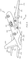
- the aircraft 200 also includes a flap actuator 260.
- the flap actuator 260 is associated with each wing 214 for actuating the inboard flap 208.
- the flap actuator 260 includes a motorized arm that is located, or housed, within the fuselage 202, or the wing fairing structure 220.
- a torque member 210 couples the flap actuator 260 with the associated inboard flap 208 to transfer an actuating/de-actuating (e.g., lowering/raising) force from the flap actuator 260 to the associated inboard flap 208.
- the torque member 210 extends through an opening 206 in the aircraft 200 (e.g., an opening 206 in the fuselage 202 or the wing fairing structure 220).
- the opening 206 in the aircraft 200 is sized and shaped to accommodate a travel path of the torque member 210 as the inboard flap 208 is lowered and raised.
- the wing spars 250 extend in a span-wise direction between a wing root 254 of the wing 214 and a wing tip 256 of the wing 214.
- the wing ribs 252 extend in a chord-wise direction between a leading edge 244 of the wing 214 and a trailing edge 242 of the wing 214.
- the wing 214 further includes a wing flap 100.
- the wing flap 100 is movably coupled with the wing 214 at the trailing edge 242 of the wing 214 proximate to the wing root 254.
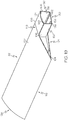
- the disclosed wing flap 100 includes a flap body 164 and a torque member 108 that is integrally formed with at least a portion of the flap body 164.
- the torque member 108 extends from the inboard end 124 of the flap body 164 in an inboard direction.
- integrally formed refers to parts (e.g., constituents or components) being of, pertaining to, or belonging as a part of a unitary whole, in which the parts are organically joined or linked during formation to form the unitary whole, and requires more than mere interconnected parts.
- the torque member 108 is integrally formed with at least one structural member 198 ( Figs. 6 and 7 ) of the flap body 164.
- structural member refers to a load-bearing element that is configured to carry a load or react to stresses applied to the wing flap 100.
- the structural members 198 that partially form the wing flap 100 include, but are not limited to, spars, ribs, stringers, and the like.
- the flap body 164 and the torque member 108 share a common structural member 198, such as a spar 106 that extends along the wing flap 100 in a span-wise direction.
- the flap body 164 includes outer skins (e.g., an upper skin 102 and a lower skin 104) and a plurality of spars 106 and the torque member 108 is integrally formed by a portion of at least one of the plurality of spars 106 that extends from the flap body 164 in an inboard direction.
- the wing flap 100 includes the upper skin 102 and the lower skin 104.
- the wing flap 100 further includes a plurality of spars 106 extending between the upper skin 102 and the lower skin 104.
- the torque member 108 being integrally formed with at least a portion of the flap body 164 allows a reduction in the cost, complexity, and/or weight of the wing flap 100 by utilizing a portion of the existing structure of the flap body 164 to form at least a portion of the torque member 108.
- the torque member 108 being integrally formed with at least a portion of the flap body 164 allows a reduction in the complexity and costs typically associated with coupling a torque member, such as a conventional torque tube, with an inboard flap of an aircraft wing.
- forming the torque member 108 from a portion of an existing structural member 198 (e.g., a spar 106) of the wing flap 100 is less costly than fabricating a metal (e.g., titanium or steel) torque tube, reduces the components and time as compared to that required to assemble and join the metal torque tube to the wing flap, and reduces concentrated loading locations formed at joints.
- a metal e.g., titanium or steel
- the torque member 108 being integrally formed with at least a portion of the flap body 164 allows a reduction in the weight of the aircraft wing and a reduction in the costs associated with production of the aircraft wing and/or the aircraft.
- forming the torque member 108 from a portion of an existing structural member 198 (e.g., a spar 106) of the wing flap 100 requires fewer joints than coupling the metal torque tube to the wing flap.
- Forming the torque member 108 from a portion of an existing structural member 198 made of carbon fiber allows a reduction in a risk of corrosion and offers increases durability as compared to a metal torque tube.
- the torque member 108 being integrally formed with at least a portion of the flap body 164 is stiffer than the metal torque tube that is coupled to the wing flap, which advantageously reduces structural deflection.
- the wing flap 100 is an example of the inboard flap 208 of the wing 214 of the aircraft 200 and the torque member 108 is an example of the torque member 210 of the inboard flap 208 ( Fig. 1 ).
- the teachings of the present disclosure are applied to one or more other flight control surfaces 232 of the aircraft 200.
- the wing flap 100 includes any suitable pivoting structure that is mounted on, or is otherwise movably coupled with, the wing body 258 of the wing 214 at the trailing edge 242 of the wing 214 ( Figs. 1 and 2 ).
- the wing flap 100 is located adjacent to the wing fairing structure 220 of the fuselage 202 of the aircraft 200.
- the wing flap 100 is movable between at least a raised (stowed, retracted, or "flaps up") position and a lowered (deployed, extended, or “flaps down”) position to alter the lift characteristics of the wing.
- the flap body 164 includes an inboard end 124 and an outboard end 126 opposite the inboard end 124.
- the flap body 164 also includes a leading end 112 and a trailing end 116 opposite the leading end 112.
- the torque member 108 includes an inboard end 180 and an outboard end 178 opposite the inboard end 180.
- the torque member 108 is integrated with the inboard end 124 of the flap body 164 and extends outward from the inboard end 124 of the flap body 164 in an inboard direction.
- the torque member 108 is located toward or proximate to (e.g., at or near) the leading end 112 of the flap body 164. In one or more examples, the torque member 108 is located toward or proximate to the trailing end 116 of the flap body 164. In one or more examples, the torque member 108 is located between the leading end 112 and the trailing end 116 of the flap body 164, such as proximate to a middle portion of the flap body 164.
- the torque member 108 has a cross-sectional shape that at least partially matches, or matches a portion of, a cross-sectional shape of the flap body 164 as viewed from the inboard end 124.
- the cross-sectional shape of the torque member 108 at least partially matching the cross-sectional shape of the flap body 164 at the inboard end 124 of the flap body 164 may reduce complexity associated with coupling the torque member 108 to the flap body 164 and may reduce the impact the torque member 108 has on the aerodynamic characteristics of the wing flap 100 and/or the aircraft 200.
- components having at least partially matching cross-sectional shapes may have, but do not require, matching sizes and/or dimensions.
- the torque member 108 has a non-circular cross-sectional shape. In one or more examples, the torque member 108 has a polygonal cross-sectional shape. In one or more examples, the torque member 108 has a rectangular cross-sectional shape. In one or more examples, the torque member 108 has a cross-sectional shape including a combination of linear and arcuate sides, such as three substantially linear sides and a fourth arcuate side connecting two linear sides to form a generally rectangular cross-sectional shape.
- the torque member 108 includes, or is at least partially formed by, a front wall 156, a rear wall 158 that is opposite the front wall 156, an upper wall 160, and a lower wall 162 that is opposite the upper wall 160. At least one of the front wall 156, the rear wall 158, the upper wall 160, and the lower wall 162 is integrally formed with the flap body 164. In one or more examples, at least one of the upper wall 160 and the lower wall 162 has a profile shape that matches a portion of the flap body 164 as viewed from the inboard end 124.
- the profile shape of one or more of the front wall 156, the rear wall 158, the upper wall 160, and the lower wall 162 is planar.
- the profile shape of one or more of the front wall 156, the rear wall 158, the upper wall 160, and the lower wall 162 is curved.
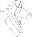
- the flap body 164 of the wing flap 100 is actuated or moved between the raised and lowered positions by way of the torque member 108, which extends through the opening 206 formed in the fuselage 202.
- the opening 206 is configured to enable a full range of motion for the torque member 108 and the associated flap body 164 during operation.
- the flap actuator 260 includes a flap support mechanism 212, also commonly referred to as a flap carriage mechanism, and a motorized actuator (not shown) that is operatively coupled with the flap support mechanism 212.
- the inboard end 180 of the torque member 108 is coupled to the flap support mechanism 212.
- Fig. 4 shows the wing flap 100 in a generally raised position with the torque member 108 extending through the opening 206 in the fuselage 202 and coupled to the flap support mechanism 212.
- the torque member 108 is configured to rotate, or is configured to be rotated, about an axis of rotation 184 to pivot or rotate the flap body 164 relative to the wing 214.
- the torque member 108 is configured to translate, or is configured to be translated, forward and aft along a travel path 186 to move the flap body 164 between a forward/raised position and an aft/lowered position.
- the travel path 186 is arcuate and, thus, the opening 206 is elongate and arcuate to enable a full range of motion of the wing flap 100 (the torque member 108 and the flap body 164 associated therewith) during operation.
- Rotation of torque member 108 enables the flap body 164 to pivot about the axis of rotation 184 during actuation of the wing flap 100.
- the axis of rotation 184 is a central longitudinal axis of the torque member 108.
- the carrier mechanism 262 includes one or more link members that are pivotally coupled to the mounting flange 182 to enable rotational and translational movement of the torque member 108, in which an instantaneous center of rotation of the torque member 108 varies along the travel path 186.
- the wing flap 100 includes an inboard flap fairing 190 that is coupled to the flap body 164 proximate to the inboard end 124 of the flap body 164.
- the inboard flap fairing 190 moves with the wing flap 100 relative to the fuselage 202 during actuation of the wing flap 100.
- the wing flap 100 also include a door 188 that is coupled to the torque member 108.
- the door 188 moves with the torque member 108 and is located relative to the fuselage 202 such that the door 188 covers at least a portion of the opening 206 ( Fig. 4 ) in the fuselage 202 during actuation of the wing flap 100.
- the wing flap 100 includes an upper skin 102 (the upper skin 102 is not shown in Figs. 7 and 8 ), a lower skin 104 that is opposite the upper skin 102, and a plurality of spars 106 (also referred to individually as spar 106 and collectively as spars 106) that extend between the upper skin 102 and the lower skin 104.
- the torque member 108 is integrally formed with at least one of the spars 106. In one or more examples, the torque member 108 is integrally formed with at least one of the upper skin 102 and the lower skin 104.
- the upper skin 102 and/or the lower skin 104 are permanently coupled with the spars 106.
- one or both of the upper skin 102 and the lower skin 104 are connected to the spars 106 by various kinds of fasteners (not shown), the spars 106 are co-cured with one or both of the upper skin 102 and/or the lower skin 104, the spars 106 are structurally bonded (e.g., adhesively bonded) with one or both of the upper skin 102 and/or the lower skin 104, or a combination thereof.
- each one of the spars 106 includes an upper spar cap 170, a lower spar cap 172 that is opposite the upper spar cap 170, and a spar web 174 that extends between the upper spar cap 170 and the lower spar cap 172.
- the upper spar cap 170 is coupled to the upper skin 102 and the lower spar cap 172 is coupled to the lower skin 104.
- Each one of the spars 106 has one of various cross-sectional shapes defined by the relative configuration of the upper spar cap 170, the lower spar cap 172, and the spar web 174.
- at least one of the spars 106 has a constant cross-sectional shape along a longitudinal axis of the spar 106.
- at least one of the spars 106 has a variable, or non-constant, cross-sectional shape along the longitudinal axis of the spar 106.
- one end of the spar web 174 is connected to a middle portion of the upper spar cap 170 (e.g., between the ends of the upper spar cap 170) and the other end of the spar web 174 is connected to a middle portion of the lower spar cap 172 (e.g., between the ends of the lower spar cap 172) and both the upper spar cap 170 and the lower spar cap 172 project from the both sides of the spar web 174 (commonly referred to as having a I-shape or H-shape in cross-section).
- the torque member 108 of the disclosed wing flap 100 is at least partially formed by an integrally formed extension of at least one structural member 198 ( Fig. 7 ) of the wing flap 100 that also at least partially forms the flap body 164.
- at least one of the spars 106 includes a spar major portion 148 and a spar extension portion 150 that extends coaxially from the spar major portion 148.
- the flap body 164 is partially formed by the spar major portion 148 of the at least one of the spars 106 and the torque member 108 is partially formed by the spar extension portion 150 of the at least one of the spars 106.
- the spar major portion 148 and the spar extension portion 150 have the same cross-sectional shape and the same dimensions.
- the spar major portion 148 and the spar extension portion 150 have different same cross-sectional shapes and/or different dimensions.
- the spar major portion 148 extends in a span-wise direction between the outboard end 126 of the flap body 164 and the inboard end 124 of the flap body 164.
- the spar major portion 148 is a structural member, or load-bearing element, of the flap body 164.
- the spar extension portion 150 extends from the inboard end 124 of the flap body 164 in the inboard direction.
- the spar extension portion 150 is a structural member, or load-bearing element, of the torque member 108.
- the spar major portion 148 and the spar extension portion 150 are integrally formed as a single part, or single piece, that forms a unitary structure or body of the spar 106.
- the spars 106 may be formed of any suitable structural material.
- the spars 106 are formed of a metallic material.
- the spars 106 are formed of a composite material, for instance, a fiber-reinforced polymer that includes a polymer matrix (e.g., a thermoset resin or a thermoplastic polymer) that is reinforced with fibers (e.g., glass, carbon, aramid, etc.), such as a carbon-fiber-reinforced polymer.
- a polymer matrix e.g., a thermoset resin or a thermoplastic polymer
- fibers e.g., glass, carbon, aramid, etc.
- At least one of the upper skin 102 and the lower skin 104 includes a skin major portion 152 and a skin extension portion 154 that extends from the skin major portion 152.
- the flap body 164 is partially formed by the skin major portion 152 and the torque member 108 is partially formed by the skin extension portion 154.
- the skin major portion 152 extends in a span-wise direction between the outboard end 126 and the inboard end 124 of the flap body 164 and in the chord-wise direction between the leading end 112 and the trailing end 116 of the flap body 164.
- the skin extension portion 154 extends from the inboard end 124 of the flap body 164 in the inboard direction.
- the skin major portion 152 and the skin extension portion 154 are integrally formed as a single part, or single piece, that forms a unitary body of the upper skin 102 and/or the lower skin 104.
- the upper skin 102 and/or the lower skin 104 may be formed of any suitable structural material.
- the upper skin 102 and/or the lower skin 104 are formed of a metallic material.
- the upper skin 102 and/or the lower skin 104 are formed of a composite material, for example a fiber-reinforced polymer that includes a polymer matrix (e.g., a thermoset resin or a thermoplastic polymer) that is reinforced with fibers (e.g., glass, carbon, aramid, etc.) such as a carbon-fiber-reinforced polymer.
- a fiber-reinforced polymer that includes a polymer matrix (e.g., a thermoset resin or a thermoplastic polymer) that is reinforced with fibers (e.g., glass, carbon, aramid, etc.) such as a carbon-fiber-reinforced polymer.
- the torque member 108 is formed by the spar extension portion 150 of one of the spars 106. In one or more examples, the torque member 108 is formed by the spar extension portion 150 of two of the spars 106. In one or more examples, the torque member 108 is formed by the spar extension portion 150 of three of the spars 106. In one or more examples, the torque member 108 is formed by the spar extension portion 150 of one of the spars 106 and an extension member 146 ( Fig. 14 ) that is coupled to the flap body 164. In one or more examples, the torque member 108 is formed by the spar extension portion 150 of two of the spars 106 and the extension member 146.
- the torque member 108 is formed by the spar extension portion 150 of two of the spars 106 and at least one extension rib 176 ( Fig. 13 ) that is coupled to the spar extension portion 150 of two of the spars 106. In one or more examples, the torque member 108 is formed by the spar extension portion 150 of one of the spars 106, the spar extension portion 150, and at least one extension rib 176. In any of these examples, the torque member 108 may also be formed by the skin extension portion 154 of at least one of the upper skin 102 and/or the lower skin 104.
- the spar extension portion 150 of a first one of the spars 106 forms the front wall 156 of the torque member 108
- the spar extension portion 150 of a second one of the spars 106 forms the rear wall 158 of the torque member 108
- the skin extension portion 154 of the upper skin 102 forms the upper wall 160 of the torque member 108
- the skin extension portion 154 of the lower skin 104 forms the lower wall 162 of the torque member 108.
- the spar major portion 148 of the first one of the spars 106 and the second one of the spars 106 (not visible in Fig. 3 ) and the skin extension portion 154 of the upper skin 102 and the lower skin 104 at least partially form the flap structure of the flap body 164.
- the flap body 164 also includes additional structural elements.
- the flap body 164 also includes additional ones of the spars 106 extending between the outboard end 126 and the inboard end 124 of the flap body 164.
- the flap body 164 also includes a plurality of ribs 166 (also referred to individually as rib 166) extending between the upper skin 102 and the lower skin 104.
- the ribs 166 extend in a chord-wise direction between adjacent pairs of the spars 106.
- the front spar 110 includes a front-spar major portion 120 and a front-spar extension portion 122 that extends coaxially from the front-spar major portion 120 in the inboard direction.
- the flap body 164 is partially formed by the front-spar major portion 120.
- the torque member 108 is partially formed by the front-spar extension portion 122.
- the front-spar major portion 120 extends between the inboard end 124 and the outboard end 126 of the flap body 164 and the front-spar extension portion 122 extends between the outboard end 178 and the inboard end 180 of the torque member 108.
- the wing flap 100 includes the front spar 110, the middle spar 118, and the rear spar 114.
- the flap body 164 is partially formed by the front-spar major portion 120.
- the torque member 108 is partially formed by the front-spar extension portion 122.
- the front-spar major portion 120 extends between the inboard end 124 and the outboard end 126 of the flap body 164 and the front-spar extension portion 122 extends between the outboard end 178 and the inboard end 180 of the torque member 108.
- the rear spar 114 terminates at the inboard end 124 of the flap body 164.
- the rear spar 114 extends between the outboard end 126 and the inboard end 124 of the flap body 164 and terminates at the inboard end 124 of the flap body 164.
- the flap body 164 is partially formed by the rear spar 114.
- the wing flap 100 also includes one or more inboard ribs 168 (also referred to individually as inboard rib 168) located at the inboard end 124 of the flap body 164.
- the inboard rib 168 is an example of one of the ribs 166 ( Fig. 8 ).
- the inboard rib 168 extends between adjacent pairs of the spars 106.
- the inboard rib 168 is located proximate to a transition between the spar major portion 148 and the spar extension portion 150 of the adjacent pair of spars 106.
- the inboard ribs 168 are configured to redistribute loads between the spars 106.
- the wing flap 100 includes a first one of the inboard ribs 168 that extends between and that is coupled to the front spar 110 and the middle spar 118.
- the first one of the inboard ribs 168 has one end that is located proximate to a transition of the front-spar major portion 120 and the front-spar extension portion 122 and an opposite end that is located proximate to a transition of the middle-spar major portion 132 and the middle-spar extension portion 134.
- the wing flap 100 also includes a second one of the inboard ribs 168 that extends between and that is coupled to the middle spar 118 and the rear spar 114.
- the second one of the inboard ribs 168 has one end that is located proximate to a transition of the middle-spar major portion 132 and the middle-spar extension portion 134 and an opposite end that is located proximate to a terminal end of the rear spar 114 (e.g., at the inboard end 124 of the flap body 164).
- two or more of the spars 106 are parallel to one another. In one or more examples, adjacent pairs of the spars 106 are parallel to each other.
- the term “parallel” has its ordinary meaning as known to those skilled in the art and refers to a condition in which a first line, extending longitudinally through the one of the spars 106, and a second line, extending longitudinally through the another one of the spars 106, share a common plane and the first line and the second line being equidistant from one another. As used herein, the term “parallel” includes exactly parallel and approximately parallel (i.e., close to parallel that still performs the desired function or achieves the desired result).
- the wing flap 100 includes the front spar 110, the middle spar 118, and the rear spar 114.
- the flap body 164 is partially formed by the front-spar major portion 120 and the middle-spar major portion 132.
- the torque member 108 is partially formed by the front-spar extension portion 122 and the middle-spar extension portion 134.
- the front-spar major portion 120 and the middle-spar major portion 132 extend between the inboard end 124 and the outboard end 126 of the flap body 164 and the front-spar extension portion 122 and the middle-spar extension portion 134 extend between the outboard end 178 and the inboard end 180 of the torque member 108.
- the rear spar 114 includes a rear-spar major portion 128 and a rear-spar extension portion 130 that extends coaxially from the rear-spar major portion 128.
- the flap body 164 is partially formed by the rear-spar major portion 128.
- the torque member 108 is partially formed by the rear-spar extension portion 130.
- the rear-spar major portion 128 extends between the inboard end 124 and the outboard end 126 of the flap body 164 and the rear-spar extension portion 130 extends from the outboard end 178 to the inboard end 180 of the torque member 108.
- the middle spar 118 is oriented at an acute angle relative to a line that is normal to and that extends from the front spar 110 such that the middle spar 118 is directed toward the front spar 110 proximate to the inboard end 180 of the torque member 108.
- the rear spar 114 is oriented at an acute angle relative to a line that is normal to and that extends from the middle spar 118 such that the rear spar 114 is directed toward the middle spar 118 proximate to the inboard end 180 of the torque member 108.
- the spars 106 converge toward the leading end 112 of the flap body 164, as illustrated in Figs. 10 and 11 . In one or more examples, the spars 106 converge toward the trailing end 116 of the flap body 164.
- the wing flap 100 includes the front spar 110, the middle spar 118, and the rear spar 114.
- the flap body 164 is partially formed by the front-spar major portion 120, the middle spar 118, and the rear-spar major portion 128.
- the torque member 108 is partially formed by the front-spar extension portion 122 and the rear-spar extension portion 130.
- the front-spar major portion 120, the middle spar 118, and the rear-spar major portion 128 extend between the inboard end 124 and the outboard end 126 of the flap body 164 and the front-spar extension portion 122 and the rear-spar extension portion 130 extend between the outboard end 178 and the inboard end 180 of the torque member 108.
- the front spar 110 and the rear spar 114 converge toward one another proximate to the inboard end 180 of the torque member 108.
- the front spar 110 and the rear spar 114 converging toward one another reduces the distance between the front spar 110 and the rear spar 114 at the inboard end 124 of the flap body 164 and at the inboard end 180 of the torque member 108.
- the wing flap 100 includes the front spar 110 and the rear spar 114.
- the flap body 164 is partially formed by the front-spar major portion 120 and the rear-spar major portion 128.
- the torque member 108 is partially formed by the front-spar extension portion 122 and the rear-spar extension portion 130.
- the front-spar major portion 120 and the rear-spar major portion 128 extend between the inboard end 124 and the outboard end 126 of the flap body 164 and the front-spar extension portion 122 and the rear-spar extension portion 130 extend between the outboard end 178 and the inboard end 180 of the torque member 108.
- the front spar 110 and the rear spar 114 converge toward one another proximate to the inboard end 180 of the torque member 108.
- the front spar 110 and the rear spar 114 converging toward one another reduces the distance between the front spar 110 and the rear spar 114 at the inboard end 124 of the flap body 164 and at the inboard end 180 of the torque member 108.
- the wing flap 100 includes the front spar 110, the middle spar 118, and the rear spar 114.
- the flap body 164 is partially formed by the front-spar major portion 120, the middle-spar major portion 132, and the rear spar 114.
- the torque member 108 is partially formed by the front-spar extension portion 122 and the middle-spar extension portion 134.
- the front-spar major portion 120, the middle-spar major portion 132, and the rear spar 114 extend between the inboard end 124 and the outboard end 126 of the flap body 164 and the front-spar extension portion 122 and the middle-spar extension portion 134 extend between the outboard end 178 and the inboard end 180 of the torque member 108.
- the extension member 146 extends outward from the inboard end 124 of the flap body 164 in the inboard direction to the inboard end 180 of the torque member 108.
- the extension member 146 is coupled to the flap body 164 in any suitable manner sufficient to transfer actuation forces from the flap support mechanism 212 ( Fig. 1 ) to the flap body 164 via the torque member 108.
- the extension member 146 is coupled to the inboard rib 168 that extends between and that is coupled to the front spar 110 and the middle spar 118.
- the inboard rib 168 includes a stiffener, or flange, that is vertically oriented and that is located on an inboard face of the inboard rib 168.
- the extension member 146 is fastened (e.g., bolted) to the stiffener of the inboard rib 168. Any other suitable joint may be used to couple an outboard end of the extension member 146 to the inboard rib 168.
- the extension member 146 and the inboard rib 168 may be formed of any suitable structural material.
- one or both of the extension member 146 and the inboard rib 168 are formed of a metallic material. In one or more examples, one or both of the extension member 146 and the inboard rib 168 are formed of a composite material (e.g., carbon fiber reinforced polymer).
- the wing flap 100 includes the front spar 110, the middle spar 118, and the rear spar 114.
- the flap body 164 is partially formed by the front-spar major portion 120, the middle-spar major portion 132, and the rear spar 114.
- the torque member 108 is partially formed by the front-spar extension portion 122 and the middle-spar extension portion 134.
- the front-spar major portion 120, the middle-spar major portion 132, and the rear spar 114 extend between the inboard end 124 and the outboard end 126 of the flap body 164 and the front-spar extension portion 122 and the middle-spar extension portion 134 extend between the outboard end 178 and the inboard end 180 of the torque member 108.
- the wing flap 100 also includes an extension rib 176 that extends between and that is coupled to the front-spar extension portion 122 of the front spar 110 and the middle-spar extension portion 134 of the middle spar 118.
- the torque member 108 is partially formed by the extension rib 176.
- the extension rib 176 is located at any one of various locations between the outboard end 178 and the inboard end 180 of the torque member 108.
- the extension rib 176 is configured to redistribute loads between the front-spar extension portion 122 of the front spar 110 and the middle-spar extension portion 134 of the middle spar 118 during actuation of the wing flap 100.
- the extension rib 176 extends between and/or is coupled to the upper skin 102 and/or the lower skin 104.
- the wing flap 100 includes a plurality of extension ribs 176, as illustrated in Fig. 13 .
- the extension ribs 176 are equally spaced along the torque member 108 between the outboard end 178 and the inboard end 180 of the torque member 108.
- the number of extension ribs 176 may vary depending, for example, on the loads applied to the torque member 108, failsafe requirements of the torque member 108, and required stiffness of the torque member 108.
- one of the extension ribs 176 is located proximate to the inboard end 180 of the torque member 108.
- At least one other of the extension ribs 176 is located between the outboard end 178 and the inboard end 180 of the torque member 108, for example, between the one of the extension ribs 176 located at the inboard end 180 of the torque member 108 and the inboard rib 168.
- the wing flap 100 includes the front spar 110 and the rear spar 114.
- the flap body 164 is partially formed by the front-spar major portion 120 and the rear spar 114.
- the torque member 108 is partially formed by the front-spar extension portion 122.
- the front-spar major portion 120 and the rear spar 114 extend between the inboard end 124 and the outboard end 126 of the flap body 164 and the front-spar extension portion 122 extends between the outboard end 178 and the inboard end 180 of the torque member 108.
- the wing flap 100 also includes the inboard rib 168 that extends between the front spar 110 and the rear spar 114 at the inboard end 124 of the flap body 164. In one or more examples, the wing flap 100 also includes the extension member 146 that is coupled to the inboard rib 168. The torque member 108 is partially formed by the extension member 146.
- the wing flap 100 also includes at least one extension rib 176 ( Fig. 13 ) that extends between the front-spar extension portion 122 of the front spar 110 and the extension member 146.
- the torque member 108 is partially formed by the extension rib 176 and the extension member 146.
- the wing flap 100 includes the front spar 110, the middle spar 118, and the rear spar 114.
- the flap body 164 is partially formed by the rear-spar major portion 128.
- the torque member 108 is partially formed by the rear-spar extension portion 130.
- the rear-spar major portion 128 extends between the inboard end 124 and the outboard end 126 of the flap body 164 and the rear-spar extension portion 130 extends between the outboard end 178 and the inboard end 180 of the torque member 108.
- the middle spar 118 includes the middle-spar major portion 132 and the middle-spar extension portion 134 that extends coaxially from the middle-spar major portion 132 in the inboard direction.
- the flap body 164 is partially formed by the middle-spar major portion 132.
- the torque member 108 is partially formed by the middle-spar extension portion 134.
- the middle-spar major portion 132 extends between the inboard end 124 and the outboard end 126 of the flap body 164 and the middle-spar extension portion 134 extends between the outboard end 178 and the inboard end 180 of the torque member 108.
- the front spar 110 terminates at the inboard end 124 of the flap body 164.
- the front spar 110 extends between the outboard end 126 and the inboard end 124 of the flap body 164 and terminates at the inboard end 124 of the flap body 164.
- the flap body 164 is partially formed by the front spar 110.
- the wing flap 100 also includes one or more of the inboard ribs 168 located at the inboard end 124 of the flap body 164.
- the wing flap 100 includes a first one of the inboard ribs 168 that extends between and that is coupled to the rear spar 114 and the middle spar 118.
- the first one of the inboard ribs 168 has one end that is located proximate to a transition of the rear-spar major portion 128 and the rear-spar extension portion 130 and an opposite end that is located proximate to a transition of the middle-spar major portion 132 and the middle-spar extension portion 134.
- the wing flap 100 also includes a second one of the inboard ribs 168 that extends between and that is coupled to the middle spar 118 and the front spar 110.
- the second one of the inboard ribs 168 has one end that is located proximate to a transition of the middle-spar major portion 132 and the middle-spar extension portion 134 and an opposite end that is located proximate to a terminal end of the front spar 110 (e.g., at the inboard end 124 of the flap body 164).
- the wing flap 100 also includes the extension member 146 that is coupled to the flap body 164 and that is located between the rear-spar extension portion 130 of the rear spar 114 and the middle-spar extension portion 134 of the middle spar 118.
- the torque member 108 is partially formed by the extension member 146.
- the extension member 146 extends outward from the inboard end 124 of the flap body 164 in the inboard direction to the inboard end 180 of the torque member 108. In one or more examples, the extension member 146 is coupled to the inboard rib 168 that extends between and that is coupled to the rear spar 114 and the middle spar 118. The extension member 146 is coupled to the flap body 164 in any suitable manner sufficient to transfer actuation forces from the flap support mechanism 212 ( Fig. 1 ) to the flap body 164 via the torque member 108.
- the wing flap 100 includes the front spar 110, the middle spar 118, and the rear spar 114.
- the flap body 164 is partially formed by the rear-spar major portion 128, the middle-spar major portion 132, and the front spar 110.
- the torque member 108 is partially formed by the rear-spar extension portion 130 and the middle-spar extension portion 134.
- the rear-spar major portion 128, the middle-spar major portion 132, and the front spar 110 extend between the inboard end 124 and the outboard end 126 of the flap body 164 and the rear-spar extension portion 130 and the middle-spar extension portion 134 extend between the outboard end 178 and the inboard end 180 of the torque member 108.
- the wing flap 100 also includes the extension rib 176 that extends between and that is coupled to the rear-spar extension portion 130 of the rear spar 114 and the middle-spar extension portion 134 of the middle spar 118.
- the torque member 108 is partially formed by the extension rib 176.
- the extension rib 176 is located at any one of various locations between the outboard end 178 and the inboard end 180 of the torque member 108.
- the extension rib 176 is configured to redistribute loads between the rear-spar extension portion 130 of the rear spar 114 and the middle-spar extension portion 134 of the middle spar 118 during actuation of the wing flap 100.
- the wing flap 100 includes a plurality of extension ribs 176, as illustrated in Fig. 17 .
- the extension ribs 176 are equally spaced along the torque member 108 between the outboard end 178 and the inboard end 180 of the torque member 108.
- the wing flap 100 includes the front spar 110 and the rear spar 114.
- the flap body 164 is partially formed by the rear-spar major portion 128 and the front spar 110.
- the torque member 108 is partially formed by the rear-spar extension portion 130.
- the rear-spar major portion 128 and the front spar 110 extend between the inboard end 124 and the outboard end 126 of the flap body 164 and the rear-spar extension portion 130 extends between the outboard end 178 and the inboard end 180 of the torque member 108.
- the wing flap 100 also includes at least one extension rib 176 ( Fig. 17 ) that extends between the rear-spar extension portion 130 of the rear spar 114 and the extension member 146.
- the torque member 108 is partially formed by the extension rib 176 and the extension member 146.
- the front-spar extension portion 122 of the front spar 110 forms the front wall 156 ( Fig. 3 ) of the torque member 108 and the middle-spar extension portion 134 of the middle spar 118 forms the rear wall 158 ( Fig. 3 ) of the torque member 108.
- the front-spar extension portion 122 of the front spar 110 forms the front wall 156 of the torque member 108 and rear-spar extension portion 130 of the rear spar 114 forms the rear wall 158 of the torque member 108.
- the front-spar extension portion 122 of the front spar 110 forms the front wall 156 of the torque member 108 and the extension member 146 forms the rear wall 158 of the torque member 108.
- the rear-spar extension portion 130 of the rear spar 114 forms the rear wall 158 ( Fig. 3 ) of the torque member 108 and the middle-spar extension portion 134 of the middle spar 118 forms the front wall 156 ( Fig. 3 ) of the torque member 108.
- the rear-spar extension portion 130 of the rear spar 114 forms the rear wall 158 of the torque member 108 and the extension member 146 forms the front wall 156 of the torque member 108.
- the skin extension portion 154 of the upper skin 102 (not visible), also referred to as upper-skin extension portion, forms the upper wall 160 ( Fig. 3 ) of the torque member 108 and the skin extension portion 154 of the lower skin 104, also referred to as lower-skin extension portion, forms the lower wall 162 of the torque member 108.
- the skin major portion 152 of the upper skin 102 also referred to as upper-skin major portion, forms an upper skin panel of the flap body 164 and the skin major portion 152 of the lower skin 104, also referred to as lower-skin major portion, forms a lower skin panel of the flap body 164.
- one or both of the upper skin 102 and/or the lower skin 104 partially form only the flap body 164. In one or more examples, one or both of the upper skin 102 and/or the lower skin 104 extends between the outboard end 126 and the inboard end 124 of the flap body 164 and terminates at the inboard end 124 of the flap body 164.
- the wing flap 100 also includes a lower-skin extension member 196 that takes the place of the lower-skin extension portion.
- the lower-skin extension member 196 extends between the inboard end 180 and the outboard end 178 of the torque member 108 and is coupled to the spar extension portion 150 of at least one of the spars 106, for example, an adjacent pair of the spars 106 or the spar 106 and the extension member 146.
- the torque member 108 is partially formed by the lower-skin extension member 196.
- the skin extension portion 154 of the upper skin 102 and the lower skin 104, the upper-skin extension member 194, and the lower-skin extension member 196 extend all the way to and terminate at the inboard end 180 of the torque member 108. In one or more examples, one or more of the skin extension portion 154 of the upper skin 102 and the lower skin 104, the upper-skin extension member 194, and/or the lower-skin extension member 196 terminates prior to the inboard end 180 of the torque member 108.
- the skin extension portion 154 of the upper skin 102 and the lower skin 104, the upper-skin extension member 194, and/or the lower-skin extension member 196 extends at least to a point on the torque member 108 in which the torque member 108 enters the fuselage 202 through the opening 206 ( Fig. 4 ).
- Failsafe measures may be beneficial to ensure continued safe flight and landing.
- Failsafe measures include: a redundant load path that is not utilized until failure of a primary load path; two or more load paths in which failure of any one of the load paths redistributes the load to another one of the load paths, each of which is capable of reacting to the entire load; and adequate reserve loading capability in each of the structural members defining a given load path such that the load path is capable to react to the entire load after failure, damage, or other impairment to one of the structural members.
- the torque member 108 of the disclosed wing flap 100 includes a failsafe configuration.
- the spar extension portion 150 of two adjacent spars 106 may form redundant load paths.
- the extension member 146 and the spar extension portion 150 of an adjacent spar 106 may form redundant load paths.
- the front-spar extension portion 122 and the middle-spar extension portion 134 define a first load path
- the middle-spar extension portion 134 and the rear-spar extension portion 130 define a second load path
- the front-spar extension portion 122 and the rear-spar extension portion 130 define a third load path.
- the front-spar extension portion 122 and the extension member 146 define a first load path
- the extension member 146 and the rear-spar extension portion 130 define a second load path
- the front-spar extension portion 122 and the rear-spar extension portion 130 define a third load path.
- the middle-spar extension portion 134 and the extension member 146 define a first load path
- the extension member 146 and the rear-spar extension portion 130 define a second load path
- the middle-spar extension portion 134 and the rear-spar extension portion 130 define a third load path.
- each one of the load paths is capable of reacting to the entire load applied to the wing flap 100 and a failure in one of the load paths (e.g., resulting from damage to one of the spars 106) may be redistributed to the other load path.
- one of the redundant load paths is loaded and another one of the redundant load paths is unloaded. Upon a failure in the loaded load path, the load is distributed to the unloaded load path.
- each one of the redundant load paths is loaded and either one of the loaded load paths is capable of reacting to the entire load upon failure of the other.
- the torque member 108 of the disclosed wing flap 100 may also include a failsafe configuration.
- the spar extension portion 150 of each one of the spars 106 has a reserve loading capacity that exceeds the entire load applied to the wing flap 100.
- the spar extension portion 150 of the spar 106 and the extension member 146 each has a reserve loading capacity that exceeds the entire load applied to the wing flap 100. In one or more examples (see, for instance, Figs.
- the front-spar extension portion 122 and the middle-spar extension portion 134 define the load path and each one of the front-spar extension portion 122 and the middle-spar extension portion 134 has a reserve loading capacity that exceeds the entire load applied to the wing flap 100.
- the middle-spar extension portion 134 and the rear-spar extension portion 130 define the load path and each one of the middle-spar extension portion 134 and the rear-spar extension portion 130 has a reserve loading capacity that exceeds the entire load applied to the wing flap 100.
- the front-spar extension portion 122 and the extension member 146 define the load path and each one of the front-spar extension portion 122 and the extension member 146 has a reserve loading capacity that exceeds the entire load applied to the wing flap 100.
- the rear-spar extension portion 130 and the extension member 146 define the load path and each one of the rear-spar extension portion 130 and the extension member 146 has a reserve loading capacity that exceeds the entire load applied to the wing flap 100.
- the method 1000 includes a step of providing the lower skin 104, the upper skin 102, and the plurality of spars 106 (Block 1004).
- the term “providing” does not require any particular delivery or receipt of the provided item. Rather, the term “providing” is used to refer to items that are available for use or that are otherwise in a state or condition of being ready for use.
- At least one of the plurality of spars 106 includes the spar major portion 148 and the spar extension portion 150 that extends from the spar major portion 148.
- the method 1000 includes a step of joining the lower skin 104, the upper skin 102, and the plurality of spars 106 together (Block 1006).
- Various methods or operations may be utilized to join the lower skin 104, the upper skin 102, and the plurality of spars 106 including, but not limited to, fastening, co-curing, bonding, or combinations thereof.
- the method 1000 includes steps of partially forming the flap body 164 with the spar major portion 148 of a first one of the plurality of spars 106 (Block 1008) and partially forming the torque member 108 with the spar extension portion 105 of the first one of the plurality of spars 106 (Block 1010).
- the method 1000 includes steps of partially forming the flap body 164 with the spar major portion 148 of a second one of the plurality of spars 106 (Block 1012) and partially forming the torque member 108 with the spar extension portion 150 of the second one of the plurality of spars 106 (Block 1014).
- the method 10000 includes steps of partially forming the flap body 164 with a third one of the plurality of spars 106 (Block 1016) and partially forming the torque member 108 with the extension member 146 that is coupled to the flap body 164 (Block 1020).
- the method 1000 includes a step of partially forming the flap body 164 with a fourth one of the plurality of spars 106.
- the method 1000 includes steps of partially forming the flap body 164 with the skin major portion 152 of the upper skin 102 (Block 1022) and partially forming the torque member 108 with the skin extension portion 154 of the upper skin 102 (Block 1024).
- the method 1000 includes steps of partially forming the flap body 164 with the upper skin 102 (Block 1026) and partially forming the torque member 108 with the upper-skin extension member 194 (Block 1028).
- the method 1000 includes steps of partially forming the flap body 164 with the skin major portion 152 of the lower skin 104 (Block 1030) and partially forming the torque member 108 with the skin extension portion 154 of the lower skin 104 (Block 1032).
- the method 1000 includes steps of partially forming the flap body 164 with the lower skin 104 (Block 1034) and partially forming the torque member 108 with the lower-skin extension member 196 (Block 1036).
- the method 1000 is further utilized for forming the wing 214 of the aircraft 200.
- the method 1000 includes a step of movably coupling the flap body 164 of the wing flap 100 to the wing body 258 of the wing 214 at the trailing edge 242 of the wing 214 (Block 1038).
- the wing flap 100 may be coupled to the wing 214 during manufacture of the wing 214.
- a conventional inboard flap of the aircraft 200 may be replaced with the wing flap 100, such as during maintenance or repair of the aircraft 200.
- the method 1000 is further utilized for forming the aircraft 200.
- the method 1000 includes a step of coupling the wing 214 to the fuselage 202 of the aircraft 200 (Block 1040).
- the method 1000 includes a step of operatively coupling the inboard end 180 of the torque member 108 with the flap actuator 260 (Block 1042).
- the torque member 108 extends into the fuselage 202 through the opening 206 in the fuselage 202.
- the method 1000 is also utilized for operating the wing flap 100.
- the method 1000 includes a step of actuating the wing flap 100 between the raised and lowered positions (Block 1044).
- the flap actuator 260 pivots and/or translates the flap body 164 of the wing flap 100 relative to the wing 214 via the torque member 108.
- Examples of the wing flap 100 and method 1000 disclosed herein may find use in a variety of potential applications, particularly in the transportation industry, including for example, aerospace applications.
- examples of the wing flap 100 and method 1000 may be used in the context of an aircraft manufacturing and service method 1100, as shown in the flow diagram of Fig. 21 , and the aircraft 200, as shown in Fig. 1 .
- Aircraft applications of the disclosed examples may include formation of the wing flap 100 and use of the wing flap 100 as a flight control surface of the aircraft 200.
- Examples of the wing flap 100 and method 1000 shown or described herein may be employed during any one or more of the stages of the manufacturing and service method 1100 shown in the flow diagram illustrated by Fig. 21 .
- components or subassemblies such as the wing flap 100 or the wing 214, corresponding to component and subassembly manufacturing (Block 1106) may be fabricated or manufactured in a manner similar to components or subassemblies produced while the aircraft 200 is in service (Block 1112).
- one or more examples of the wing flap 100, method 1000, or combinations thereof may be utilized during system integration (Block 1108) and/or certification and delivery (Block 1110).
- one or more examples of the wing flap 100, method 1000, or a combination thereof may be utilized, for example and without limitation, while the aircraft 200 is in service (Block 1112) and during maintenance and service (Block 1114).
- the principles disclosed herein may be applied to other industries, such as the automotive industry. Accordingly, in addition to aircraft, the principles disclosed herein may apply to other vehicles, (e.g., land vehicles, marine vehicles, space vehicles, etc.).
- the disclosure further comprises the following illustrative, non-exhaustive enumerated examples, which may or may not be claimed:
- example means that one or more feature, structure, element, component, characteristic and/or operational step described in connection with the example is included in at least one embodiment and or implementation of the subject matter according to the present disclosure.
- phrase “an example” and similar language throughout the present disclosure may, but do not necessarily, refer to the same example.
- the subject matter characterizing any one example may, but does not necessarily, include the subject matter characterizing any other example.
- a system, apparatus, structure, article, element, component, or hardware “configured to” perform a specified function is indeed capable of performing the specified function without any alteration, rather than merely having potential to perform the specified function after further modification.
- the system, apparatus, structure, article, element, component, or hardware “configured to” perform a specified function is specifically selected, created, implemented, utilized, programmed, and/or designed for the purpose of performing the specified function.
- "configured to” denotes existing characteristics of a system, apparatus, structure, article, element, component, or hardware that enable the system, apparatus, structure, article, element, component, or hardware to perform the specified function without further modification.
- a system, apparatus, structure, article, element, component, or hardware described as being “configured to” perform a particular function may additionally or alternatively be described as being “adapted to” and/or as being “operative to” perform that function.
- Coupled refers to two or more elements that are joined, linked, fastened, connected, put in communication, or otherwise associated (e.g., mechanically, electrically, fluidly, optically, electromagnetically) with one another.
- the elements may be associated directly or indirectly: element A may be directly associated with element B; or element A may be indirectly associated with element B, for example, via another element C. It will be understood that not all associations among the various disclosed elements are necessarily represented. Accordingly, couplings other than those depicted in the figures may also exist.
- the phrase "at least one of', when used with a list of items, means different combinations of one or more of the listed items may be used and only one of each item in the list may be needed.
- “at least one of item A, item B, and item C” may include, without limitation, item A or item A and item B.
- “At least one of item A, item B, and item C” also may include item A, item B, and item C, or item B and item C.
- “At least one of' may be, for example, without limitation, two of item A, one of item B, and ten of item C; four of item B and seven of item C; and other suitable combinations.
- Figs. 20 and 21 referred to above, the blocks may represent operations and/or portions thereof and lines connecting the various blocks do not imply any particular order or dependency of the operations or portions thereof. Blocks represented by dashed lines indicate alternative operations and/or portions thereof. Dashed lines, if any, connecting the various blocks represent alternative dependencies of the operations or portions thereof. It will be understood that not all dependencies among the various disclosed operations are necessarily represented. Figs. 20 and 21 and the accompanying disclosure describing the operations of the disclosed methods set forth herein should not be interpreted as necessarily determining a sequence in which the operations are to be performed. Rather, although one illustrative order is indicated, it is to be understood that the sequence of the operations may be modified when appropriate. Accordingly, modifications, additions and/or omissions may be made to the operations illustrated and certain operations may be performed in a different order or simultaneously. Additionally, those skilled in the art will appreciate that not all operations described need be performed.
Abstract
Description
- The present disclosure is generally related to aircraft and, more particularly, to an aircraft wing flap having a torque member that is integrally formed with at least a portion of a flap body and a method for forming the wing flap.
- Fixed-wing aircraft typically include various flight control surfaces that enable adjustment and control of the aircraft's flight. For example, flaps mounted on trailing edges of wings modify the effective contour of the wings and, thus, modify the lift characteristics of the wings. In certain types of flap systems, an inboard flap includes a torque member that is used to move the flap between stowed and deployed positions. Typically, the torque member extends into the side of the fuselage, or into a wing fairing structure of the fuselage, and is coupled to a flap support mechanism that controls movement of the flap.
- In many flap systems, the torque member is a tubular structure having a circular cross-sectional shape, commonly referred to as a torque tube. The torque tube is typically coupled to a structural member of the flap, such as an inboard rib. However, achieving appropriate structural and load-bearing performance can require a heavy torque tube and large and complex couplings that increase the weight and cost of the aircraft. Additionally, some flap systems utilize a failsafe torque tube that includes a dual torque tube design that further increases the cost, weight, and complexity of the aircraft.
- Accordingly, those skilled in the art continue with research and development efforts in the field of aircraft wing flap actuation.
- A wing flap is disclosed that includes a flap body and a torque member being integrally formed with at least a portion of the flap body.
- A wing of an aircraft is disclosed that includes a wing body and a wing flap. The wing flap includes a flap body movably coupled to the wing body and a torque member being integrally formed with at least a portion of the flap body.
- A method is disclosed that includes a step of integrally forming a torque member with at least a portion of a flap body to form a wing flap. The flap body is configured to be movably coupled with a wing of an aircraft. The torque member is configured to be coupled to a flap actuator of the aircraft.
- Examples of the disclosed wing flap and method will become apparent from the following detailed description, the accompanying drawings and the appended claims.
-
-
Fig. 1 is a schematic, perspective view of an aircraft according to one or more examples of the disclosure; -
Fig. 2 is a schematic, perspective view of a wing of the aircraft according to one or more examples of the disclosure; -
Fig. 3 is a schematic, perspective view of a wing flap according to one or more examples of the disclosure; -
Fig. 4 is a schematic, interior, perspective view of a portion of the aircraft showing a torque member of a wing flap extending through an opening in a fuselage of the aircraft according to one or more examples of the disclosure; -
Fig. 5 is a schematic, partial, perspective view of a wing flap according to one or more examples of the disclosure; -
Fig. 6 is a schematic, elevation, cross-sectional view of a wing flap according to one or more examples of the disclosure; -
Fig. 7 is a schematic, partial, plan view of a wing flap according to one or more examples of the disclosure; -
Fig. 8 is a schematic, plan view of a wing flap according to one or more examples of the disclosure; -
Fig. 9 is a schematic, partial, plan view of a wing flap according to one or more examples of the disclosure; -
Fig. 10 is a schematic, partial, plan view of a wing flap according to one or more examples of the disclosure; -
Fig. 11 is a schematic, partial, plan view of a wing flap according to one or more examples of the disclosure; -
Fig. 12 is a schematic, partial, plan view of a wing flap according to one or more examples of the disclosure; -
Fig. 13 is a schematic, partial, plan view of a wing flap according to one or more examples of the disclosure; -
Fig. 14 is a schematic, partial, plan view of a wing flap according to one or more examples of the disclosure; -
Fig. 15 is a schematic, partial, plan view of a wing flap according to one or more examples of the disclosure; -
Fig. 16 is a schematic, partial, plan view of a wing flap according to one or more examples of the disclosure; -
Fig. 17 is a schematic, partial, plan view of a wing flap according to one or more examples of the disclosure; -
Fig. 18 is a schematic, partial, plan view of a wing flap according to one or more examples of the disclosure; -
Fig. 19 is a schematic, perspective view of a wing flap according to one or more examples of the disclosure; -
Fig. 20 is a flow diagram of a method, according to one or more examples of the disclosure, of making the wing flap ofFigs. 3-19 ; and -
Fig. 21 is a flow diagram of an aircraft production and service methodology according to one or more examples of the disclosure. - The following detailed description refers to the accompanying drawings, which illustrate specific examples described by the disclosure. Like reference numerals may refer to the same feature, element, or component in the different drawings.
- Illustrative, non-exhaustive examples, which may be, but are not necessarily, claimed, of the subject matter according the present disclosure are provided below.
-
Fig. 1 is an illustrative example of anaircraft 200. In the illustrative example, theaircraft 200 is a fixed-wing aircraft. Theaircraft 200 includes afuselage 202, a pair of wings 214 (also referred to individually as wing 214), and apropulsion system 216. Theaircraft 200 also includes a plurality of high-level systems, such as, but not limited to, anelectrical system 226, ahydraulic system 228, and/or anenvironmental system 230. Any number of other systems may also be included. - The
fuselage 202 is the main body of theaircraft 200 and includes any suitable central structure configured to hold a crew, one or more passengers, and/or cargo. In the illustrative example, thefuselage 202 is an elongate, generally cylindrical fuselage. Thefuselage 202 includes a nose portion at a forward end of thefuselage 202 and a tail portion at an aft end of thefuselage 202. As used herein, the terms "forward" and "aft" have their ordinary meaning as known to those skilled in the art and refer to positions relative to a direction of movement of theaircraft 200. The tail portion may also include avertical stabilizer 240 andhorizontal stabilizers 238. - The
fuselage 202 includes anairframe 222 that defines aninterior 224, which may include a passenger compartment and/or a cargo compartment. A wing fairing structure 220 (e.g., fuselage/wing fairing) may also be provided at each interface between thefuselage 202 and thewing 214 and may extend from proximate (at or near) thefuselage 202 to proximate thewing 214 associated therewith. - The
wings 214 include any suitable airfoil structures that are configured to provide lift to theaircraft 200. In the illustrative example, thewings 214 are elongate structures extending from a lower portion of thefuselage 202 in a swept wing, tapered planform. In one or more examples, thewings 214 are straight or delta-shaped. In one or more examples, thewings 214 are trapezoidal, constant, elliptical, semi-elliptical, or other configurations known in the art. In the illustrative example, thepropulsion system 216 includes two turbofan engines mounted to thewings 214, for example, by pylons. In one or more examples, each engine is housed in a nacelle, which includes an inlet and a nozzle. In one or more examples, the engines are be mounted to thefuselage 202 or other aircraft structures, such as the tail portion. In one or more examples, thepropulsion system 216 includes more or fewer engines and other types of engines (e.g., turboprop engines) may be used. - The
aircraft 200 includes various flight control surfaces 232. Theflight control surfaces 232 include any pivoting aerodynamic device that is used to adjust and control flight and aerodynamic characteristics of theaircraft 200. Examples of theflight control surfaces 232 include aninboard flap 208 and/or anoutboard flap 218 that are located on the trailing end of thewings 214, anelevator 234 that is located on the trailing end of thehorizontal stabilizers 238, arudder 236 that is located on the trailing end of thevertical stabilizer 240, and other control surfaces, such as leading end flaps, ailerons, and spoilers. As used herein, the terms "inboard" and "outboard" have their ordinary meaning as known to those skilled in the art and refer to positions relative to a center line of theaircraft 200.
In one or more examples, the inboard flap 208 (also referred to collectively as inboard flaps 208) and/or the outboard flap 218 (also referred to collectively as outboard flaps 218) include any suitable structure mounted on the trailing edge of thewing 214 and configured to pivot, rotate, and/or translate (e.g., forward and aft) relative to thewing 214. The inboard flaps 208 and/or theoutboard flaps 218 are configured to alter the lift characteristics of thewing 214. In one or more examples, theinboard flaps 208 and/or theoutboard flaps 218 are movable between at least a raised (stowed, retracted, or "flaps up") position and a lowered (deployed, extended, or "flaps down") position. In one or more examples, theinboard flaps 208 and/or theoutboard flaps 218 are pivotable about a fixed axis. In one or more examples, theinboard flaps 208 and/or theoutboard flaps 218 pivot through a predetermined path, which is generally arcuate of curved. - In one or more examples, the
aircraft 200 also includes aflap actuator 260. Theflap actuator 260 is associated with eachwing 214 for actuating theinboard flap 208. In one or more examples, theflap actuator 260 includes a motorized arm that is located, or housed, within thefuselage 202, or thewing fairing structure 220. - In one or more examples, a
torque member 210 couples theflap actuator 260 with the associatedinboard flap 208 to transfer an actuating/de-actuating (e.g., lowering/raising) force from theflap actuator 260 to the associatedinboard flap 208. Thetorque member 210 extends through anopening 206 in the aircraft 200 (e.g., anopening 206 in thefuselage 202 or the wing fairing structure 220). Theopening 206 in theaircraft 200 is sized and shaped to accommodate a travel path of thetorque member 210 as theinboard flap 208 is lowered and raised. -
Fig. 2 is an illustrative example of thewing 214. Thewing 214 is any one of various wing structures that includes awing body 258. Thewing body 258 is formed of various structural members including, but not limited to, anupper wing skin 246, alower wing skin 248, a plurality of wing spars 250 that extend between theupper wing skin 246 and thelower wing skin 248, and a plurality ofwing ribs 252 that extend between theupper wing skin 246 and thelower wing skin 248. These structural members are coupled together by any one of various methods including, but not limited to, connection by various kinds of fasteners, co-curing, or integrally forming. The wing spars 250 extend in a span-wise direction between awing root 254 of thewing 214 and awing tip 256 of thewing 214. Thewing ribs 252 extend in a chord-wise direction between aleading edge 244 of thewing 214 and a trailingedge 242 of thewing 214. Thewing 214 further includes awing flap 100. In one or more examples, thewing flap 100 is movably coupled with thewing 214 at the trailingedge 242 of thewing 214 proximate to thewing root 254. - Referring to
Figs. 3-19 , disclosed are various examples of thewing flap 100. The disclosedwing flap 100 includes aflap body 164 and atorque member 108 that is integrally formed with at least a portion of theflap body 164. Thetorque member 108 extends from theinboard end 124 of theflap body 164 in an inboard direction. As used herein, the phrase "integrally formed" refers to parts (e.g., constituents or components) being of, pertaining to, or belonging as a part of a unitary whole, in which the parts are organically joined or linked during formation to form the unitary whole, and requires more than mere interconnected parts. - In one or more examples, the
torque member 108 is integrally formed with at least one structural member 198 (Figs. 6 and 7 ) of theflap body 164. As used herein, the phrase "structural member," with reference to any one of a plurality ofstructural members 198 that partially form thewing flap 100, refers to a load-bearing element that is configured to carry a load or react to stresses applied to thewing flap 100. Generally, thestructural members 198 that partially form thewing flap 100 include, but are not limited to, spars, ribs, stringers, and the like. For example, theflap body 164 and thetorque member 108 share a commonstructural member 198, such as aspar 106 that extends along thewing flap 100 in a span-wise direction. In one or more examples, theflap body 164 includes outer skins (e.g., anupper skin 102 and a lower skin 104) and a plurality ofspars 106 and thetorque member 108 is integrally formed by a portion of at least one of the plurality ofspars 106 that extends from theflap body 164 in an inboard direction. Accordingly, and as discussed in more detail below, thewing flap 100 includes theupper skin 102 and thelower skin 104. Thewing flap 100 further includes a plurality ofspars 106 extending between theupper skin 102 and thelower skin 104. - The
torque member 108 being integrally formed with at least a portion of theflap body 164 allows a reduction in the cost, complexity, and/or weight of thewing flap 100 by utilizing a portion of the existing structure of theflap body 164 to form at least a portion of thetorque member 108. Thetorque member 108 being integrally formed with at least a portion of theflap body 164 allows a reduction in the complexity and costs typically associated with coupling a torque member, such as a conventional torque tube, with an inboard flap of an aircraft wing. For example, forming thetorque member 108 from a portion of an existing structural member 198 (e.g., a spar 106) of thewing flap 100 is less costly than fabricating a metal (e.g., titanium or steel) torque tube, reduces the components and time as compared to that required to assemble and join the metal torque tube to the wing flap, and reduces concentrated loading locations formed at joints. - The
torque member 108 being integrally formed with at least a portion of theflap body 164 allows a reduction in the weight of the aircraft wing and a reduction in the costs associated with production of the aircraft wing and/or the aircraft. For example, forming thetorque member 108 from a portion of an existing structural member 198 (e.g., a spar 106) of thewing flap 100 requires fewer joints than coupling the metal torque tube to the wing flap. Forming thetorque member 108 from a portion of an existingstructural member 198 made of carbon fiber allows a reduction in a risk of corrosion and offers increases durability as compared to a metal torque tube. Thetorque member 108 being integrally formed with at least a portion of theflap body 164 is stiffer than the metal torque tube that is coupled to the wing flap, which advantageously reduces structural deflection. - The
wing flap 100 is an example of theinboard flap 208 of thewing 214 of theaircraft 200 and thetorque member 108 is an example of thetorque member 210 of the inboard flap 208 (Fig. 1 ). In one or more examples, the teachings of the present disclosure are applied to one or more otherflight control surfaces 232 of theaircraft 200. - In one or more examples, the
wing flap 100 includes any suitable pivoting structure that is mounted on, or is otherwise movably coupled with, thewing body 258 of thewing 214 at the trailingedge 242 of the wing 214 (Figs. 1 and2 ). In one or more examples, thewing flap 100 is located adjacent to thewing fairing structure 220 of thefuselage 202 of theaircraft 200. During operation of thewing flap 100, thewing flap 100 is movable between at least a raised (stowed, retracted, or "flaps up") position and a lowered (deployed, extended, or "flaps down") position to alter the lift characteristics of the wing. - Referring to
Fig. 3 , theflap body 164 includes aninboard end 124 and anoutboard end 126 opposite theinboard end 124. Theflap body 164 also includes aleading end 112 and a trailingend 116 opposite theleading end 112. Thetorque member 108 includes aninboard end 180 and anoutboard end 178 opposite theinboard end 180. In one or more examples, thetorque member 108 is integrated with theinboard end 124 of theflap body 164 and extends outward from theinboard end 124 of theflap body 164 in an inboard direction. - In one or more examples, the
torque member 108 is located toward or proximate to (e.g., at or near) theleading end 112 of theflap body 164. In one or more examples, thetorque member 108 is located toward or proximate to the trailingend 116 of theflap body 164. In one or more examples, thetorque member 108 is located between theleading end 112 and the trailingend 116 of theflap body 164, such as proximate to a middle portion of theflap body 164. - In one or more examples, the
torque member 108 has a cross-sectional shape that at least partially matches, or matches a portion of, a cross-sectional shape of theflap body 164 as viewed from theinboard end 124. The cross-sectional shape of thetorque member 108 at least partially matching the cross-sectional shape of theflap body 164 at theinboard end 124 of theflap body 164 may reduce complexity associated with coupling thetorque member 108 to theflap body 164 and may reduce the impact thetorque member 108 has on the aerodynamic characteristics of thewing flap 100 and/or theaircraft 200. As used herein, components having at least partially matching cross-sectional shapes may have, but do not require, matching sizes and/or dimensions. - In one or more examples, the
torque member 108 has a non-circular cross-sectional shape. In one or more examples, thetorque member 108 has a polygonal cross-sectional shape. In one or more examples, thetorque member 108 has a rectangular cross-sectional shape. In one or more examples, thetorque member 108 has a cross-sectional shape including a combination of linear and arcuate sides, such as three substantially linear sides and a fourth arcuate side connecting two linear sides to form a generally rectangular cross-sectional shape. - In one or more examples, the
torque member 108 includes, or is at least partially formed by, afront wall 156, arear wall 158 that is opposite thefront wall 156, anupper wall 160, and alower wall 162 that is opposite theupper wall 160. At least one of thefront wall 156, therear wall 158, theupper wall 160, and thelower wall 162 is integrally formed with theflap body 164. In one or more examples, at least one of theupper wall 160 and thelower wall 162 has a profile shape that matches a portion of theflap body 164 as viewed from theinboard end 124. - A profile shape of each one of the
front wall 156, therear wall 158, theupper wall 160, and thelower wall 162, as viewed from theinboard end 124, defines the cross sectional shape of thetorque member 108. In one or more examples, the profile shape of one or more of thefront wall 156, therear wall 158, theupper wall 160, and thelower wall 162 is planar. In one or more examples, the profile shape of one or more of thefront wall 156, therear wall 158, theupper wall 160, and thelower wall 162 is curved. - Referring to
Fig. 4 , theflap body 164 of thewing flap 100 is actuated or moved between the raised and lowered positions by way of thetorque member 108, which extends through theopening 206 formed in thefuselage 202. Theopening 206 is configured to enable a full range of motion for thetorque member 108 and the associatedflap body 164 during operation. In one or more examples, theflap actuator 260 includes aflap support mechanism 212, also commonly referred to as a flap carriage mechanism, and a motorized actuator (not shown) that is operatively coupled with theflap support mechanism 212. In one or more examples, theinboard end 180 of thetorque member 108 is coupled to theflap support mechanism 212. -
Fig. 4 shows thewing flap 100 in a generally raised position with thetorque member 108 extending through theopening 206 in thefuselage 202 and coupled to theflap support mechanism 212. In one or more examples, thetorque member 108 is configured to rotate, or is configured to be rotated, about an axis ofrotation 184 to pivot or rotate theflap body 164 relative to thewing 214. Alternatively, or in addition to, in one or more examples, thetorque member 108 is configured to translate, or is configured to be translated, forward and aft along atravel path 186 to move theflap body 164 between a forward/raised position and an aft/lowered position. In one or more examples, thetravel path 186 is arcuate and, thus, theopening 206 is elongate and arcuate to enable a full range of motion of the wing flap 100 (thetorque member 108 and theflap body 164 associated therewith) during operation. Rotation oftorque member 108 enables theflap body 164 to pivot about the axis ofrotation 184 during actuation of thewing flap 100. In one or more examples, the axis ofrotation 184 is a central longitudinal axis of thetorque member 108. - In one or more examples, the
torque member 108 also includes a mountingflange 182 that is located at theoutboard end 178 of thetorque member 108 and that is configured to be coupled to theflap support mechanism 212. In one or more examples, theflap support mechanism 212 includes acarrier mechanism 262, which is also commonly referred to as a carrier beam. Thecarrier mechanism 262 is coupled to theinboard end 180 of thetorque member 108 and transfers motion to thetorque member 108 during actuation of theflap support mechanism 212. In one or more examples, thecarrier mechanism 262 includes one or more link members that are pivotally coupled to the mountingflange 182 to enable rotational and translational movement of thetorque member 108, in which an instantaneous center of rotation of thetorque member 108 varies along thetravel path 186. - Referring to
Fig. 5 , in one or more examples, thewing flap 100 includes an inboard flap fairing 190 that is coupled to theflap body 164 proximate to theinboard end 124 of theflap body 164. The inboard flap fairing 190 moves with thewing flap 100 relative to thefuselage 202 during actuation of thewing flap 100. In one or more examples, thewing flap 100 also include adoor 188 that is coupled to thetorque member 108. Thedoor 188 moves with thetorque member 108 and is located relative to thefuselage 202 such that thedoor 188 covers at least a portion of the opening 206 (Fig. 4 ) in thefuselage 202 during actuation of thewing flap 100. - Referring to
Figs. 6-8 , in one or more examples, thewing flap 100 includes an upper skin 102 (theupper skin 102 is not shown inFigs. 7 and8 ), alower skin 104 that is opposite theupper skin 102, and a plurality of spars 106 (also referred to individually asspar 106 and collectively as spars 106) that extend between theupper skin 102 and thelower skin 104. In one or more examples, thetorque member 108 is integrally formed with at least one of thespars 106. In one or more examples, thetorque member 108 is integrally formed with at least one of theupper skin 102 and thelower skin 104. - In one or more examples, the
upper skin 102 and/or thelower skin 104 are permanently coupled with thespars 106. As examples, one or both of theupper skin 102 and thelower skin 104 are connected to thespars 106 by various kinds of fasteners (not shown), thespars 106 are co-cured with one or both of theupper skin 102 and/or thelower skin 104, thespars 106 are structurally bonded (e.g., adhesively bonded) with one or both of theupper skin 102 and/or thelower skin 104, or a combination thereof. - Referring to
Fig. 6 , in one or more examples, each one of thespars 106 includes anupper spar cap 170, alower spar cap 172 that is opposite theupper spar cap 170, and aspar web 174 that extends between theupper spar cap 170 and thelower spar cap 172. Theupper spar cap 170 is coupled to theupper skin 102 and thelower spar cap 172 is coupled to thelower skin 104. Each one of thespars 106 has one of various cross-sectional shapes defined by the relative configuration of theupper spar cap 170, thelower spar cap 172, and thespar web 174. In one or more examples, at least one of thespars 106 has a constant cross-sectional shape along a longitudinal axis of thespar 106. In one or more examples, at least one of thespars 106 has a variable, or non-constant, cross-sectional shape along the longitudinal axis of thespar 106. - In one or more examples of the
spar 106, one end of thespar web 174 is connected to an end of theupper spar cap 170 and the other end of thespar web 174 is connected to an end of thelower spar cap 172 and both theupper spar cap 170 and thelower spar cap 172 project from the same side of the spar web 174 (commonly referred to as having a C-shape or U-shape in cross-section). - In one or more example of the
spar 106, one end of thespar web 174 is connected to a middle portion of the upper spar cap 170 (e.g., between the ends of the upper spar cap 170) and the other end of thespar web 174 is connected to a middle portion of the lower spar cap 172 (e.g., between the ends of the lower spar cap 172) and both theupper spar cap 170 and thelower spar cap 172 project from the both sides of the spar web 174 (commonly referred to as having a I-shape or H-shape in cross-section). - Referring to
Figs. 7 and8 , thetorque member 108 of the disclosedwing flap 100 is at least partially formed by an integrally formed extension of at least one structural member 198 (Fig. 7 ) of thewing flap 100 that also at least partially forms theflap body 164. In one or more examples, at least one of thespars 106 includes a sparmajor portion 148 and aspar extension portion 150 that extends coaxially from the sparmajor portion 148. Theflap body 164 is partially formed by the sparmajor portion 148 of the at least one of thespars 106 and thetorque member 108 is partially formed by thespar extension portion 150 of the at least one of thespars 106. In one or more examples, the sparmajor portion 148 and thespar extension portion 150 have the same cross-sectional shape and the same dimensions. In one or more examples, the sparmajor portion 148 and thespar extension portion 150 have different same cross-sectional shapes and/or different dimensions. - In one or more examples, the spar
major portion 148 extends in a span-wise direction between theoutboard end 126 of theflap body 164 and theinboard end 124 of theflap body 164. The sparmajor portion 148 is a structural member, or load-bearing element, of theflap body 164. Thespar extension portion 150 extends from theinboard end 124 of theflap body 164 in the inboard direction. Thespar extension portion 150 is a structural member, or load-bearing element, of thetorque member 108. - The spar
major portion 148 and thespar extension portion 150 are integrally formed as a single part, or single piece, that forms a unitary structure or body of thespar 106. Thespars 106 may be formed of any suitable structural material. In one or more examples, thespars 106 are formed of a metallic material. In one or more examples, thespars 106 are formed of a composite material, for instance, a fiber-reinforced polymer that includes a polymer matrix (e.g., a thermoset resin or a thermoplastic polymer) that is reinforced with fibers (e.g., glass, carbon, aramid, etc.), such as a carbon-fiber-reinforced polymer. - In one or more examples, at least one of the
upper skin 102 and thelower skin 104 includes a skinmajor portion 152 and askin extension portion 154 that extends from the skinmajor portion 152. Theflap body 164 is partially formed by the skinmajor portion 152 and thetorque member 108 is partially formed by theskin extension portion 154. - In one or more examples, the skin
major portion 152 extends in a span-wise direction between theoutboard end 126 and theinboard end 124 of theflap body 164 and in the chord-wise direction between theleading end 112 and the trailingend 116 of theflap body 164. Theskin extension portion 154 extends from theinboard end 124 of theflap body 164 in the inboard direction. - The skin
major portion 152 and theskin extension portion 154 are integrally formed as a single part, or single piece, that forms a unitary body of theupper skin 102 and/or thelower skin 104. Theupper skin 102 and/or thelower skin 104 may be formed of any suitable structural material. In one or more examples, theupper skin 102 and/or thelower skin 104 are formed of a metallic material. In one or more examples, theupper skin 102 and/or thelower skin 104 are formed of a composite material, for example a fiber-reinforced polymer that includes a polymer matrix (e.g., a thermoset resin or a thermoplastic polymer) that is reinforced with fibers (e.g., glass, carbon, aramid, etc.) such as a carbon-fiber-reinforced polymer. - In one or more examples, the
torque member 108 is formed by thespar extension portion 150 of one of thespars 106. In one or more examples, thetorque member 108 is formed by thespar extension portion 150 of two of thespars 106. In one or more examples, thetorque member 108 is formed by thespar extension portion 150 of three of thespars 106. In one or more examples, thetorque member 108 is formed by thespar extension portion 150 of one of thespars 106 and an extension member 146 (Fig. 14 ) that is coupled to theflap body 164. In one or more examples, thetorque member 108 is formed by thespar extension portion 150 of two of thespars 106 and theextension member 146. In one or more examples, thetorque member 108 is formed by thespar extension portion 150 of two of thespars 106 and at least one extension rib 176 (Fig. 13 ) that is coupled to thespar extension portion 150 of two of thespars 106. In one or more examples, thetorque member 108 is formed by thespar extension portion 150 of one of thespars 106, thespar extension portion 150, and at least oneextension rib 176. In any of these examples, thetorque member 108 may also be formed by theskin extension portion 154 of at least one of theupper skin 102 and/or thelower skin 104. - In one or more examples, and as best illustrated in
Fig. 3 , thespar extension portion 150 of a first one of thespars 106 forms thefront wall 156 of thetorque member 108, thespar extension portion 150 of a second one of thespars 106 forms therear wall 158 of thetorque member 108, theskin extension portion 154 of theupper skin 102 forms theupper wall 160 of thetorque member 108, and theskin extension portion 154 of thelower skin 104 forms thelower wall 162 of thetorque member 108. The sparmajor portion 148 of the first one of thespars 106 and the second one of the spars 106 (not visible inFig. 3 ) and theskin extension portion 154 of theupper skin 102 and thelower skin 104 at least partially form the flap structure of theflap body 164. - Referring to
Fig. 8 , in one or more examples, theflap body 164 also includes additional structural elements. In one or more examples, theflap body 164 also includes additional ones of thespars 106 extending between theoutboard end 126 and theinboard end 124 of theflap body 164. In one or more examples, theflap body 164 also includes a plurality of ribs 166 (also referred to individually as rib 166) extending between theupper skin 102 and thelower skin 104. In one or more examples, theribs 166 extend in a chord-wise direction between adjacent pairs of thespars 106. - Referring to
Figs. 9-18 , in one or more examples, the plurality ofspars 106 includes afront spar 110 that is located proximate to theleading end 112 of theflap body 164. In one or more examples, the plurality ofspars 106 also includes arear spar 114 that is located proximate to the trailingend 116 of thewing flap 100. In one or more examples, the plurality ofspars 106 also includes amiddle spar 118 that is located between thefront spar 110 and therear spar 114. InFigs. 9-18 , theupper skin 102 is not shown. - Referring to
Figs. 9-14 , in examples of the disclosedwing flap 100, thefront spar 110 includes a front-sparmajor portion 120 and a front-spar extension portion 122 that extends coaxially from the front-sparmajor portion 120 in the inboard direction. Theflap body 164 is partially formed by the front-sparmajor portion 120. Thetorque member 108 is partially formed by the front-spar extension portion 122. In one or more examples, the front-sparmajor portion 120 extends between theinboard end 124 and theoutboard end 126 of theflap body 164 and the front-spar extension portion 122 extends between theoutboard end 178 and theinboard end 180 of thetorque member 108. Utilization of thefront spar 110 as a common structural member of thewing flap 100 that integrally forms thetorque member 108 with theflap body 164 naturally positions thetorque member 108 toward or proximate to theleading end 112 of theflap body 164. - Referring to
Fig. 9 , in one or more examples, thewing flap 100 includes thefront spar 110, themiddle spar 118, and therear spar 114. Theflap body 164 is partially formed by the front-sparmajor portion 120. Thetorque member 108 is partially formed by the front-spar extension portion 122. In one or more examples, the front-sparmajor portion 120 extends between theinboard end 124 and theoutboard end 126 of theflap body 164 and the front-spar extension portion 122 extends between theoutboard end 178 and theinboard end 180 of thetorque member 108. - In one or more examples, the
middle spar 118 includes a middle-sparmajor portion 132 and a middle-spar extension portion 134 that extends coaxially from the middle-sparmajor portion 132 in the inboard direction. Theflap body 164 is partially formed by the middle-sparmajor portion 132. Thetorque member 108 is partially formed by the middle-spar extension portion 134. In one or more examples, the middle-sparmajor portion 132 extends between theinboard end 124 and theoutboard end 126 of theflap body 164 and the middle-spar extension portion 134 extends between theoutboard end 178 and theinboard end 180 of thetorque member 108. - In one or more examples, the
rear spar 114, and/or any additional ones of thespars 106, terminates at theinboard end 124 of theflap body 164. In one or more examples, therear spar 114 extends between theoutboard end 126 and theinboard end 124 of theflap body 164 and terminates at theinboard end 124 of theflap body 164. Theflap body 164 is partially formed by therear spar 114. - In one or more examples, the
wing flap 100 also includes one or more inboard ribs 168 (also referred to individually as inboard rib 168) located at theinboard end 124 of theflap body 164. Theinboard rib 168 is an example of one of the ribs 166 (Fig. 8 ). In one or more examples, theinboard rib 168 extends between adjacent pairs of thespars 106. In one or more examples, theinboard rib 168 is located proximate to a transition between the sparmajor portion 148 and thespar extension portion 150 of the adjacent pair ofspars 106. Theinboard ribs 168 are configured to redistribute loads between thespars 106. - In one or more examples, the
wing flap 100 includes a first one of theinboard ribs 168 that extends between and that is coupled to thefront spar 110 and themiddle spar 118. For example, the first one of theinboard ribs 168 has one end that is located proximate to a transition of the front-sparmajor portion 120 and the front-spar extension portion 122 and an opposite end that is located proximate to a transition of the middle-sparmajor portion 132 and the middle-spar extension portion 134. In one or more examples, thewing flap 100 also includes a second one of theinboard ribs 168 that extends between and that is coupled to themiddle spar 118 and therear spar 114. For example, the second one of theinboard ribs 168 has one end that is located proximate to a transition of the middle-sparmajor portion 132 and the middle-spar extension portion 134 and an opposite end that is located proximate to a terminal end of the rear spar 114 (e.g., at theinboard end 124 of the flap body 164). - In one or more examples, two or more of the
spars 106 are parallel to one another. In one or more examples, adjacent pairs of thespars 106 are parallel to each other. As used herein, the term "parallel" has its ordinary meaning as known to those skilled in the art and refers to a condition in which a first line, extending longitudinally through the one of thespars 106, and a second line, extending longitudinally through the another one of thespars 106, share a common plane and the first line and the second line being equidistant from one another. As used herein, the term "parallel" includes exactly parallel and approximately parallel (i.e., close to parallel that still performs the desired function or achieves the desired result). - Referring to
Figs. 10 and11 , in one or more examples, thewing flap 100 includes thefront spar 110, themiddle spar 118, and therear spar 114. Theflap body 164 is partially formed by the front-sparmajor portion 120 and the middle-sparmajor portion 132. Thetorque member 108 is partially formed by the front-spar extension portion 122 and the middle-spar extension portion 134. In one or more examples, the front-sparmajor portion 120 and the middle-sparmajor portion 132 extend between theinboard end 124 and theoutboard end 126 of theflap body 164 and the front-spar extension portion 122 and the middle-spar extension portion 134 extend between theoutboard end 178 and theinboard end 180 of thetorque member 108. - In one or more examples, the
rear spar 114 includes a rear-sparmajor portion 128 and a rear-spar extension portion 130 that extends coaxially from the rear-sparmajor portion 128. Theflap body 164 is partially formed by the rear-sparmajor portion 128. Thetorque member 108 is partially formed by the rear-spar extension portion 130. In one or more examples, the rear-sparmajor portion 128 extends between theinboard end 124 and theoutboard end 126 of theflap body 164 and the rear-spar extension portion 130 extends from theoutboard end 178 to theinboard end 180 of thetorque member 108. - In one or more examples, two or more of the
spars 106 are not parallel to one another. In one or more examples, adjacent pairs of thespars 106 are not parallel to each other. In one or more examples, two or more of thespars 106 converge toward each other proximate to (e.g., at or near) theinboard end 180 of thetorque member 108. For example, at least two of thefront spar 110, themiddle spar 118, and therear spar 114 converge toward one another proximate to theinboard end 180 of thetorque member 108. - In one or more examples, the
front spar 110, themiddle spar 118, and therear spar 114 converge toward one another proximate to theinboard end 180 of thetorque member 108. Thefront spar 110, themiddle spar 118, and therear spar 114 converging toward one another reduces the distance between thefront spar 110 and themiddle spar 118 and reduces the distance between themiddle spar 118 and therear spar 114 at theinboard end 124 of theflap body 164 and at theinboard end 180 of thetorque member 108. Reducing the distance between thefront spar 110 and themiddle spar 118 may eliminate the need for theinboard rib 168 extending between thefront spar 110 and the middle spar 118 (Fig. 9 ). Reducing the distance between themiddle spar 118 and therear spar 114 may eliminate the need for theinboard rib 168 extending between themiddle spar 118 and the rear spar 114 (Fig. 9 ). - Referring to
Fig. 10 , in one or more examples, themiddle spar 118 is oriented at an acute angle relative to a line that is normal to and that extends from thefront spar 110 such that themiddle spar 118 is directed toward thefront spar 110 proximate to theinboard end 180 of thetorque member 108. Therear spar 114 is oriented at an acute angle relative to a line that is normal to and that extends from themiddle spar 118 such that therear spar 114 is directed toward themiddle spar 118 proximate to theinboard end 180 of thetorque member 108. - Referring to
Fig. 11 , in one or more examples, themiddle spar 118 is oriented at an acute angle relative to a line that is normal to and that extends from thefront spar 110 such that themiddle spar 118 is directed toward thefront spar 110 proximate to theinboard end 180 of thetorque member 108. Afirst segment 114A of therear spar 114 is oriented parallel to thefront spar 110. Asecond segment 114B of therear spar 114 is oriented at an acute angle relative to a line that is normal to and that extends from themiddle spar 118 such that thesecond segment 114B of therear spar 114 is directed toward themiddle spar 118 proximate to theinboard end 180 of thetorque member 108. - In one or more examples, the
spars 106 converge toward theleading end 112 of theflap body 164, as illustrated inFigs. 10 and11 . In one or more examples, thespars 106 converge toward the trailingend 116 of theflap body 164. - In one or more examples, the
wing flap 100 includes thefront spar 110, themiddle spar 118, and therear spar 114. Theflap body 164 is partially formed by the front-sparmajor portion 120, themiddle spar 118, and the rear-sparmajor portion 128. Thetorque member 108 is partially formed by the front-spar extension portion 122 and the rear-spar extension portion 130. In one or more examples, the front-sparmajor portion 120, themiddle spar 118, and the rear-sparmajor portion 128 extend between theinboard end 124 and theoutboard end 126 of theflap body 164 and the front-spar extension portion 122 and the rear-spar extension portion 130 extend between theoutboard end 178 and theinboard end 180 of thetorque member 108. Thefront spar 110 and therear spar 114 converge toward one another proximate to theinboard end 180 of thetorque member 108. Thefront spar 110 and therear spar 114 converging toward one another reduces the distance between thefront spar 110 and therear spar 114 at theinboard end 124 of theflap body 164 and at theinboard end 180 of thetorque member 108. - In one or more examples, the
wing flap 100 includes thefront spar 110 and therear spar 114. Theflap body 164 is partially formed by the front-sparmajor portion 120 and the rear-sparmajor portion 128. Thetorque member 108 is partially formed by the front-spar extension portion 122 and the rear-spar extension portion 130. In one or more examples, the front-sparmajor portion 120 and the rear-sparmajor portion 128 extend between theinboard end 124 and theoutboard end 126 of theflap body 164 and the front-spar extension portion 122 and the rear-spar extension portion 130 extend between theoutboard end 178 and theinboard end 180 of thetorque member 108. Thefront spar 110 and therear spar 114 converge toward one another proximate to theinboard end 180 of thetorque member 108. Thefront spar 110 and therear spar 114 converging toward one another reduces the distance between thefront spar 110 and therear spar 114 at theinboard end 124 of theflap body 164 and at theinboard end 180 of thetorque member 108. - Referring to
Fig. 12 , in one or more examples, thewing flap 100 includes thefront spar 110, themiddle spar 118, and therear spar 114. Theflap body 164 is partially formed by the front-sparmajor portion 120, the middle-sparmajor portion 132, and therear spar 114. Thetorque member 108 is partially formed by the front-spar extension portion 122 and the middle-spar extension portion 134. In one or more examples, the front-sparmajor portion 120, the middle-sparmajor portion 132, and therear spar 114 extend between theinboard end 124 and theoutboard end 126 of theflap body 164 and the front-spar extension portion 122 and the middle-spar extension portion 134 extend between theoutboard end 178 and theinboard end 180 of thetorque member 108. - In one or more examples, the
wing flap 100 also includes theextension member 146 that is coupled to theflap body 164 and that is located between the front-spar extension portion 122 of thefront spar 110 and the middle-spar extension portion 134 of themiddle spar 118. Thetorque member 108 is partially formed by theextension member 146. - In one or more examples, the
extension member 146 extends outward from theinboard end 124 of theflap body 164 in the inboard direction to theinboard end 180 of thetorque member 108. Theextension member 146 is coupled to theflap body 164 in any suitable manner sufficient to transfer actuation forces from the flap support mechanism 212 (Fig. 1 ) to theflap body 164 via thetorque member 108. - In one or more examples, the
extension member 146 is coupled to theinboard rib 168 that extends between and that is coupled to thefront spar 110 and themiddle spar 118. In one or more examples, theinboard rib 168 includes a stiffener, or flange, that is vertically oriented and that is located on an inboard face of theinboard rib 168. Theextension member 146 is fastened (e.g., bolted) to the stiffener of theinboard rib 168. Any other suitable joint may be used to couple an outboard end of theextension member 146 to theinboard rib 168. Theextension member 146 and theinboard rib 168 may be formed of any suitable structural material. In one or more examples, one or both of theextension member 146 and theinboard rib 168 are formed of a metallic material. In one or more examples, one or both of theextension member 146 and theinboard rib 168 are formed of a composite material (e.g., carbon fiber reinforced polymer). - Referring to
Fig. 13 , in one or more examples, thewing flap 100 includes thefront spar 110, themiddle spar 118, and therear spar 114. Theflap body 164 is partially formed by the front-sparmajor portion 120, the middle-sparmajor portion 132, and therear spar 114. Thetorque member 108 is partially formed by the front-spar extension portion 122 and the middle-spar extension portion 134. In one or more examples, the front-sparmajor portion 120, the middle-sparmajor portion 132, and therear spar 114 extend between theinboard end 124 and theoutboard end 126 of theflap body 164 and the front-spar extension portion 122 and the middle-spar extension portion 134 extend between theoutboard end 178 and theinboard end 180 of thetorque member 108. - In one or more examples, the
wing flap 100 also includes anextension rib 176 that extends between and that is coupled to the front-spar extension portion 122 of thefront spar 110 and the middle-spar extension portion 134 of themiddle spar 118. Thetorque member 108 is partially formed by theextension rib 176. - In one or more examples, the
extension rib 176 is located at any one of various locations between theoutboard end 178 and theinboard end 180 of thetorque member 108. Theextension rib 176 is configured to redistribute loads between the front-spar extension portion 122 of thefront spar 110 and the middle-spar extension portion 134 of themiddle spar 118 during actuation of thewing flap 100. In one or more examples, theextension rib 176 extends between and/or is coupled to theupper skin 102 and/or thelower skin 104. - In one or more examples, the
wing flap 100 includes a plurality ofextension ribs 176, as illustrated inFig. 13 . In one or more examples, theextension ribs 176 are equally spaced along thetorque member 108 between theoutboard end 178 and theinboard end 180 of thetorque member 108. The number ofextension ribs 176 may vary depending, for example, on the loads applied to thetorque member 108, failsafe requirements of thetorque member 108, and required stiffness of thetorque member 108. In one or more examples, one of theextension ribs 176 is located proximate to theinboard end 180 of thetorque member 108. In one or more examples, at least one other of theextension ribs 176 is located between theoutboard end 178 and theinboard end 180 of thetorque member 108, for example, between the one of theextension ribs 176 located at theinboard end 180 of thetorque member 108 and theinboard rib 168. - Referring to
Fig. 14 , in one or more examples, thewing flap 100 includes thefront spar 110 and therear spar 114. Theflap body 164 is partially formed by the front-sparmajor portion 120 and therear spar 114. Thetorque member 108 is partially formed by the front-spar extension portion 122. In one or more examples, the front-sparmajor portion 120 and therear spar 114 extend between theinboard end 124 and theoutboard end 126 of theflap body 164 and the front-spar extension portion 122 extends between theoutboard end 178 and theinboard end 180 of thetorque member 108. - In one or more examples, the
wing flap 100 also includes theinboard rib 168 that extends between thefront spar 110 and therear spar 114 at theinboard end 124 of theflap body 164. In one or more examples, thewing flap 100 also includes theextension member 146 that is coupled to theinboard rib 168. Thetorque member 108 is partially formed by theextension member 146. - While not illustrated in
Fig. 14 , in one or more examples, thewing flap 100 also includes at least one extension rib 176 (Fig. 13 ) that extends between the front-spar extension portion 122 of thefront spar 110 and theextension member 146. Thetorque member 108 is partially formed by theextension rib 176 and theextension member 146. - Referring to
Figs. 15-18 , in examples of the disclosedwing flap 100, therear spar 114 includes the rear-sparmajor portion 128 and the rear-spar extension portion 130 that extends coaxially from the rear-sparmajor portion 128 in the inboard direction. Theflap body 164 is partially formed by the rear-sparmajor portion 128. Thetorque member 108 is partially formed by the rear-spar extension portion 130. In one or more examples, the rear-sparmajor portion 128 extends between theinboard end 124 and theoutboard end 126 of theflap body 164 and the rear-spar extension portion 130 extends between theoutboard end 178 and theinboard end 180 of thetorque member 108. Utilization of therear spar 114 as a common structural member of thewing flap 100 that integrally forms thetorque member 108 with theflap body 164 naturally positions thetorque member 108 toward or proximate to the trailingend 116 of theflap body 164. - Referring to
Fig. 15 , in one or more examples, thewing flap 100 includes thefront spar 110, themiddle spar 118, and therear spar 114. Theflap body 164 is partially formed by the rear-sparmajor portion 128. Thetorque member 108 is partially formed by the rear-spar extension portion 130. In one or more examples, the rear-sparmajor portion 128 extends between theinboard end 124 and theoutboard end 126 of theflap body 164 and the rear-spar extension portion 130 extends between theoutboard end 178 and theinboard end 180 of thetorque member 108. - In one or more examples, the
middle spar 118 includes the middle-sparmajor portion 132 and the middle-spar extension portion 134 that extends coaxially from the middle-sparmajor portion 132 in the inboard direction. Theflap body 164 is partially formed by the middle-sparmajor portion 132. Thetorque member 108 is partially formed by the middle-spar extension portion 134. In one or more examples, the middle-sparmajor portion 132 extends between theinboard end 124 and theoutboard end 126 of theflap body 164 and the middle-spar extension portion 134 extends between theoutboard end 178 and theinboard end 180 of thetorque member 108. - In one or more examples, the
front spar 110, and/or any additional ones of thespars 106, terminates at theinboard end 124 of theflap body 164. In one or more examples, thefront spar 110 extends between theoutboard end 126 and theinboard end 124 of theflap body 164 and terminates at theinboard end 124 of theflap body 164. Theflap body 164 is partially formed by thefront spar 110. - In one or more examples, the
wing flap 100 also includes one or more of theinboard ribs 168 located at theinboard end 124 of theflap body 164. In one or more examples, thewing flap 100 includes a first one of theinboard ribs 168 that extends between and that is coupled to therear spar 114 and themiddle spar 118. For example, the first one of theinboard ribs 168 has one end that is located proximate to a transition of the rear-sparmajor portion 128 and the rear-spar extension portion 130 and an opposite end that is located proximate to a transition of the middle-sparmajor portion 132 and the middle-spar extension portion 134. In one or more examples, thewing flap 100 also includes a second one of theinboard ribs 168 that extends between and that is coupled to themiddle spar 118 and thefront spar 110. For example, the second one of theinboard ribs 168 has one end that is located proximate to a transition of the middle-sparmajor portion 132 and the middle-spar extension portion 134 and an opposite end that is located proximate to a terminal end of the front spar 110 (e.g., at theinboard end 124 of the flap body 164). - Referring to
Fig. 16 , in one or more examples, thewing flap 100 includes thefront spar 110, themiddle spar 118, and therear spar 114. Theflap body 164 is partially formed by the rear-sparmajor portion 128, the middle-sparmajor portion 132, and thefront spar 110. Thetorque member 108 is partially formed by the rear-spar extension portion 130 and the middle-spar extension portion 134. In one or more examples, the rear-sparmajor portion 128, the middle-sparmajor portion 132, and thefront spar 110 extend between theinboard end 124 and theoutboard end 126 of theflap body 164 and the rear-spar extension portion 130 and the middle-spar extension portion 134 extend between theoutboard end 178 and theinboard end 180 of thetorque member 108. - In one or more examples, the
wing flap 100 also includes theextension member 146 that is coupled to theflap body 164 and that is located between the rear-spar extension portion 130 of therear spar 114 and the middle-spar extension portion 134 of themiddle spar 118. Thetorque member 108 is partially formed by theextension member 146. - In one or more examples, the
extension member 146 extends outward from theinboard end 124 of theflap body 164 in the inboard direction to theinboard end 180 of thetorque member 108. In one or more examples, theextension member 146 is coupled to theinboard rib 168 that extends between and that is coupled to therear spar 114 and themiddle spar 118. Theextension member 146 is coupled to theflap body 164 in any suitable manner sufficient to transfer actuation forces from the flap support mechanism 212 (Fig. 1 ) to theflap body 164 via thetorque member 108. - Referring to
Fig. 17 , in one or more examples, thewing flap 100 includes thefront spar 110, themiddle spar 118, and therear spar 114. Theflap body 164 is partially formed by the rear-sparmajor portion 128, the middle-sparmajor portion 132, and thefront spar 110. Thetorque member 108 is partially formed by the rear-spar extension portion 130 and the middle-spar extension portion 134. In one or more examples, the rear-sparmajor portion 128, the middle-sparmajor portion 132, and thefront spar 110 extend between theinboard end 124 and theoutboard end 126 of theflap body 164 and the rear-spar extension portion 130 and the middle-spar extension portion 134 extend between theoutboard end 178 and theinboard end 180 of thetorque member 108. - In one or more examples, the
wing flap 100 also includes theextension rib 176 that extends between and that is coupled to the rear-spar extension portion 130 of therear spar 114 and the middle-spar extension portion 134 of themiddle spar 118. Thetorque member 108 is partially formed by theextension rib 176. - In one or more examples, the
extension rib 176 is located at any one of various locations between theoutboard end 178 and theinboard end 180 of thetorque member 108. Theextension rib 176 is configured to redistribute loads between the rear-spar extension portion 130 of therear spar 114 and the middle-spar extension portion 134 of themiddle spar 118 during actuation of thewing flap 100. In an example, thewing flap 100 includes a plurality ofextension ribs 176, as illustrated inFig. 17 . In one or more examples, theextension ribs 176 are equally spaced along thetorque member 108 between theoutboard end 178 and theinboard end 180 of thetorque member 108. - Referring to
Fig. 18 , in one or more examples, thewing flap 100 includes thefront spar 110 and therear spar 114. Theflap body 164 is partially formed by the rear-sparmajor portion 128 and thefront spar 110. Thetorque member 108 is partially formed by the rear-spar extension portion 130. In one or more examples, the rear-sparmajor portion 128 and thefront spar 110 extend between theinboard end 124 and theoutboard end 126 of theflap body 164 and the rear-spar extension portion 130 extends between theoutboard end 178 and theinboard end 180 of thetorque member 108. - In one or more examples, the
wing flap 100 also includes theinboard rib 168 that extends between thefront spar 110 and therear spar 114 at theinboard end 124 of theflap body 164. In one or more examples, thewing flap 100 also includes theextension member 146 that is coupled to theinboard rib 168. Thetorque member 108 is partially formed by theextension member 146. - While not illustrated in
Fig. 18 , in one or more examples, thewing flap 100 also includes at least one extension rib 176 (Fig. 17 ) that extends between the rear-spar extension portion 130 of therear spar 114 and theextension member 146. Thetorque member 108 is partially formed by theextension rib 176 and theextension member 146. - In the examples shown in
Figs. 9 ,12 , and13 , the front-spar extension portion 122 of thefront spar 110 forms the front wall 156 (Fig. 3 ) of thetorque member 108 and the middle-spar extension portion 134 of themiddle spar 118 forms the rear wall 158 (Fig. 3 ) of thetorque member 108. In the examples shown inFigs. 10 and11 , the front-spar extension portion 122 of thefront spar 110 forms thefront wall 156 of thetorque member 108 and rear-spar extension portion 130 of therear spar 114 forms therear wall 158 of thetorque member 108. In the example shown inFig. 14 , the front-spar extension portion 122 of thefront spar 110 forms thefront wall 156 of thetorque member 108 and theextension member 146 forms therear wall 158 of thetorque member 108. - In the examples shown in
Figs. 15-17 , the rear-spar extension portion 130 of therear spar 114 forms the rear wall 158 (Fig. 3 ) of thetorque member 108 and the middle-spar extension portion 134 of themiddle spar 118 forms the front wall 156 (Fig. 3 ) of thetorque member 108. In the example shown inFig. 18 , the rear-spar extension portion 130 of therear spar 114 forms therear wall 158 of thetorque member 108 and theextension member 146 forms thefront wall 156 of thetorque member 108. - In the examples shown in
Figs. 9-18 , theskin extension portion 154 of the upper skin 102 (not visible), also referred to as upper-skin extension portion, forms the upper wall 160 (Fig. 3 ) of thetorque member 108 and theskin extension portion 154 of thelower skin 104, also referred to as lower-skin extension portion, forms thelower wall 162 of thetorque member 108. The skinmajor portion 152 of theupper skin 102, also referred to as upper-skin major portion, forms an upper skin panel of theflap body 164 and the skinmajor portion 152 of thelower skin 104, also referred to as lower-skin major portion, forms a lower skin panel of theflap body 164. - Referring to
Fig. 19 , in one or more examples, one or both of theupper skin 102 and/or thelower skin 104 partially form only theflap body 164. In one or more examples, one or both of theupper skin 102 and/or thelower skin 104 extends between theoutboard end 126 and theinboard end 124 of theflap body 164 and terminates at theinboard end 124 of theflap body 164. - In one or more examples, the
wing flap 100 also includes an upper-skin extension member 194 that takes the place of the upper-skin extension portion. In one or more examples, the upper-skin extension member 194 extends between theinboard end 180 and theoutboard end 178 of thetorque member 108 and is coupled to thespar extension portion 150 of at least one of thespars 106, for example, an adjacent pair of thespars 106 or thespar 106 and theextension member 146. Thetorque member 108 is partially formed by the upper-skin extension member 194. - In one or more examples, the
wing flap 100 also includes a lower-skin extension member 196 that takes the place of the lower-skin extension portion. In one or more examples, the lower-skin extension member 196 extends between theinboard end 180 and theoutboard end 178 of thetorque member 108 and is coupled to thespar extension portion 150 of at least one of thespars 106, for example, an adjacent pair of thespars 106 or thespar 106 and theextension member 146. Thetorque member 108 is partially formed by the lower-skin extension member 196. - In the illustrated examples, the
skin extension portion 154 of theupper skin 102 and thelower skin 104, the upper-skin extension member 194, and the lower-skin extension member 196 extend all the way to and terminate at theinboard end 180 of thetorque member 108. In one or more examples, one or more of theskin extension portion 154 of theupper skin 102 and thelower skin 104, the upper-skin extension member 194, and/or the lower-skin extension member 196 terminates prior to theinboard end 180 of thetorque member 108. In one or more examples, theskin extension portion 154 of theupper skin 102 and thelower skin 104, the upper-skin extension member 194, and/or the lower-skin extension member 196 extends at least to a point on thetorque member 108 in which thetorque member 108 enters thefuselage 202 through the opening 206 (Fig. 4 ). - In some aerospace implementations, failsafe measures may be beneficial to ensure continued safe flight and landing. Failsafe measures include: a redundant load path that is not utilized until failure of a primary load path; two or more load paths in which failure of any one of the load paths redistributes the load to another one of the load paths, each of which is capable of reacting to the entire load; and adequate reserve loading capability in each of the structural members defining a given load path such that the load path is capable to react to the entire load after failure, damage, or other impairment to one of the structural members.
- In one or more examples, such as the illustrative examples shown in
Figs. 10-12 and16 , thetorque member 108 of the disclosedwing flap 100 includes a failsafe configuration. In one or more examples, thespar extension portion 150 of twoadjacent spars 106 may form redundant load paths. In one or more examples, theextension member 146 and thespar extension portion 150 of anadjacent spar 106 may form redundant load paths. In one or more examples (Figs. 10 and11 ), the front-spar extension portion 122 and the middle-spar extension portion 134 define a first load path, the middle-spar extension portion 134 and the rear-spar extension portion 130 define a second load path, and the front-spar extension portion 122 and the rear-spar extension portion 130 define a third load path. In one or more examples (see, for example,Fig. 12 ), the front-spar extension portion 122 and theextension member 146 define a first load path, theextension member 146 and the rear-spar extension portion 130 define a second load path, and the front-spar extension portion 122 and the rear-spar extension portion 130 define a third load path. In one or more examples (see, for example,Fig. 16 ), the middle-spar extension portion 134 and theextension member 146 define a first load path, theextension member 146 and the rear-spar extension portion 130 define a second load path, and the middle-spar extension portion 134 and the rear-spar extension portion 130 define a third load path. In these examples, each one of the load paths is capable of reacting to the entire load applied to thewing flap 100 and a failure in one of the load paths (e.g., resulting from damage to one of the spars 106) may be redistributed to the other load path. In one or more examples, one of the redundant load paths is loaded and another one of the redundant load paths is unloaded. Upon a failure in the loaded load path, the load is distributed to the unloaded load path. In one or more examples, each one of the redundant load paths is loaded and either one of the loaded load paths is capable of reacting to the entire load upon failure of the other. - In some examples, such as the illustrative examples shown in
Figs. 9 ,13-15 ,17, and 18 , thetorque member 108 of the disclosedwing flap 100 may also include a failsafe configuration. In one or more examples, thespar extension portion 150 of each one of thespars 106 has a reserve loading capacity that exceeds the entire load applied to thewing flap 100. In one or more examples, thespar extension portion 150 of thespar 106 and theextension member 146 each has a reserve loading capacity that exceeds the entire load applied to thewing flap 100. In one or more examples (see, for instance,Figs. 9 and13 ), the front-spar extension portion 122 and the middle-spar extension portion 134 define the load path and each one of the front-spar extension portion 122 and the middle-spar extension portion 134 has a reserve loading capacity that exceeds the entire load applied to thewing flap 100. In one or more examples (Figs. 15 and17 ), the middle-spar extension portion 134 and the rear-spar extension portion 130 define the load path and each one of the middle-spar extension portion 134 and the rear-spar extension portion 130 has a reserve loading capacity that exceeds the entire load applied to thewing flap 100. In one or more examples(see, for instance,Fig. 14 ), the front-spar extension portion 122 and theextension member 146 define the load path and each one of the front-spar extension portion 122 and theextension member 146 has a reserve loading capacity that exceeds the entire load applied to thewing flap 100. In one or more examples (see, for instance,Fig. 18 ), the rear-spar extension portion 130 and theextension member 146 define the load path and each one of the rear-spar extension portion 130 and theextension member 146 has a reserve loading capacity that exceeds the entire load applied to thewing flap 100. - Referring to
Fig. 20 , also disclosed is one ormore examples method 1000. In one or more examples, themethod 1000 is utilized for forming thewing flap 100. In one or more examples, themethod 1000 includes a step of integrally forming thetorque member 108 with at least a portion of theflap body 164 to form the wing flap 100 (Block 1002). Theflap body 164 is configured to be movably coupled with thewing 214 of theaircraft 200. Thetorque member 108 is configured to be operatively coupled with theflap actuator 260 of theaircraft 200. - In one or more examples, the
method 1000 includes a step of providing thelower skin 104, theupper skin 102, and the plurality of spars 106 (Block 1004). As used herein, the term "providing" does not require any particular delivery or receipt of the provided item. Rather, the term "providing" is used to refer to items that are available for use or that are otherwise in a state or condition of being ready for use. At least one of the plurality ofspars 106 includes the sparmajor portion 148 and thespar extension portion 150 that extends from the sparmajor portion 148. - In one or more examples, the
method 1000 includes a step of joining thelower skin 104, theupper skin 102, and the plurality ofspars 106 together (Block 1006). Various methods or operations may be utilized to join thelower skin 104, theupper skin 102, and the plurality ofspars 106 including, but not limited to, fastening, co-curing, bonding, or combinations thereof. - In one or more examples, the
method 1000 includes steps of partially forming theflap body 164 with the sparmajor portion 148 of a first one of the plurality of spars 106 (Block 1008) and partially forming thetorque member 108 with the spar extension portion 105 of the first one of the plurality of spars 106 (Block 1010). - In one or more examples, the
method 1000 includes steps of partially forming theflap body 164 with the sparmajor portion 148 of a second one of the plurality of spars 106 (Block 1012) and partially forming thetorque member 108 with thespar extension portion 150 of the second one of the plurality of spars 106 (Block 1014). Alternatively, the method 10000 includes steps of partially forming theflap body 164 with a third one of the plurality of spars 106 (Block 1016) and partially forming thetorque member 108 with theextension member 146 that is coupled to the flap body 164 (Block 1020). In one or more examples, themethod 1000 includes a step of partially forming theflap body 164 with a fourth one of the plurality ofspars 106. - In one or more examples, the
method 1000 includes steps of partially forming theflap body 164 with the skinmajor portion 152 of the upper skin 102 (Block 1022) and partially forming thetorque member 108 with theskin extension portion 154 of the upper skin 102 (Block 1024). Alternatively, in one or more examples, themethod 1000 includes steps of partially forming theflap body 164 with the upper skin 102 (Block 1026) and partially forming thetorque member 108 with the upper-skin extension member 194 (Block 1028). - In one or more examples, the
method 1000 includes steps of partially forming theflap body 164 with the skinmajor portion 152 of the lower skin 104 (Block 1030) and partially forming thetorque member 108 with theskin extension portion 154 of the lower skin 104 (Block 1032). Alternatively, in one or more examples, themethod 1000 includes steps of partially forming theflap body 164 with the lower skin 104 (Block 1034) and partially forming thetorque member 108 with the lower-skin extension member 196 (Block 1036). - In one or more examples, the
method 1000 is further utilized for forming thewing 214 of theaircraft 200. In one or more examples, themethod 1000 includes a step of movably coupling theflap body 164 of thewing flap 100 to thewing body 258 of thewing 214 at the trailingedge 242 of the wing 214 (Block 1038). In accordance with themethod 1000, thewing flap 100 may be coupled to thewing 214 during manufacture of thewing 214. Alternatively, in accordance with themethod 1000, a conventional inboard flap of theaircraft 200 may be replaced with thewing flap 100, such as during maintenance or repair of theaircraft 200. - In one or more examples, the
method 1000 is further utilized for forming theaircraft 200. In one or more examples, themethod 1000 includes a step of coupling thewing 214 to thefuselage 202 of the aircraft 200 (Block 1040). In one or more examples, themethod 1000 includes a step of operatively coupling theinboard end 180 of thetorque member 108 with the flap actuator 260 (Block 1042). In one or more examples, thetorque member 108 extends into thefuselage 202 through theopening 206 in thefuselage 202. - In one or more examples, the
method 1000 is also utilized for operating thewing flap 100. In one or more examples, themethod 1000 includes a step of actuating thewing flap 100 between the raised and lowered positions (Block 1044). In one or more examples, theflap actuator 260 pivots and/or translates theflap body 164 of thewing flap 100 relative to thewing 214 via thetorque member 108. - Examples of the
wing flap 100 andmethod 1000 disclosed herein may find use in a variety of potential applications, particularly in the transportation industry, including for example, aerospace applications. Referring now toFigs. 1 and21 , examples of thewing flap 100 andmethod 1000 may be used in the context of an aircraft manufacturing andservice method 1100, as shown in the flow diagram ofFig. 21 , and theaircraft 200, as shown inFig. 1 . Aircraft applications of the disclosed examples may include formation of thewing flap 100 and use of thewing flap 100 as a flight control surface of theaircraft 200. - As shown in
Fig. 21 , during pre-production, theillustrative method 1100 may include specification and design of the aircraft 200 (Block 1102) and material procurement (Block 1104). During production of theaircraft 200, component and subassembly manufacturing (Block 1106) and system integration (Block 1108) of theaircraft 200 may take place. Thereafter, theaircraft 200 may go through certification and delivery (Block 1110) to be placed in service (Block 1112). The disclosedwing flap 100 andmethod 1000 may form a portion of component and subassembly manufacturing (Block 1106) and/or system integration (Block 1108). Routine maintenance and service (Block 1114) may include modification, reconfiguration, refurbishment, etc. of one or more systems of theaircraft 200, such as repair and/or replacement of inboard wing flaps. - Each of the processes of illustrative method may be performed or carried out by a system integrator, a third party, and/or an operator (e.g., a customer). For the purposes of this description, a system integrator may include, without limitation, any number of aircraft manufacturers and major-system subcontractors; a third party may include, without limitation, any number of vendors, subcontractors, and suppliers; and an operator may be an airline, leasing company, military entity, service organization, and so on.
- Examples of the
wing flap 100 andmethod 1000 shown or described herein may be employed during any one or more of the stages of the manufacturing andservice method 1100 shown in the flow diagram illustrated byFig. 21 . For example, components or subassemblies, such as thewing flap 100 or thewing 214, corresponding to component and subassembly manufacturing (Block 1106) may be fabricated or manufactured in a manner similar to components or subassemblies produced while theaircraft 200 is in service (Block 1112). Also, one or more examples of thewing flap 100,method 1000, or combinations thereof may be utilized during system integration (Block 1108) and/or certification and delivery (Block 1110). Similarly, one or more examples of thewing flap 100,method 1000, or a combination thereof, may be utilized, for example and without limitation, while theaircraft 200 is in service (Block 1112) and during maintenance and service (Block 1114). - Although an aerospace example is shown, the principles disclosed herein may be applied to other industries, such as the automotive industry. Accordingly, in addition to aircraft, the principles disclosed herein may apply to other vehicles, (e.g., land vehicles, marine vehicles, space vehicles, etc.).
- The disclosure further comprises the following illustrative, non-exhaustive enumerated examples, which may or may not be claimed:
- A1. A
wing flap 100 comprising: aflap body 164; and atorque member 210 being integrally formed with at least a portion of theflap body 164. - A2. The
wing flap 100 of example A1, wherein thetorque member 210 has a non-circular cross-sectional shape. - A3. The
wing flap 100 of example A1 or A2, further comprising: anupper skin 102;
alower skin 104 opposite theupper skin 102; and a plurality ofspars 106 that extend between theupper skin 102 and thelower skin 104, wherein thetorque member 210 is integrally formed with at least one of the plurality ofspars 106. - A4. The
wing flap 100 of example A3, wherein: at least one of the plurality ofspars 106 comprises a sparmajor portion 148 and aspar extension portion 150 that extends from the sparmajor portion 148; theflap body 164 is partially formed by the sparmajor portion 148; and thetorque member 210 is partially formed by thespar extension portion 150. - A5. The
wing flap 100 of example A3 or A4, wherein thetorque member 210 is integrally formed with at least one of theupper skin 102 and thelower skin 104. - A6. The
wing flap 100 of any of examples A3 to A5, wherein: the plurality ofspars 106 comprises afront spar 110, thefront spar 110 comprising a front-sparmajor portion 120 and a front-spar extension portion 122 that extends from the front-sparmajor portion 120; theflap body 164 is partially formed by the front-sparmajor portion 120; and thetorque member 210 is partially formed by the front-spar extension portion 122. - A7. The
wing flap 100 of example A6, wherein: the plurality ofspars 106 further comprises amiddle spar 118, themiddle spar 118 comprising a middle-sparmajor portion 132 and a middle-spar extension portion 134 that extends from the middle-sparmajor portion 132; theflap body 164 is partially formed by the middle-sparmajor portion 132; and thetorque member 210 is partially formed by the middle-spar extension portion 134. - A8. The
wing flap 100 of example A7, wherein: the plurality ofspars 106 further comprises arear spar 114, therear spar 114 comprising a rear-sparmajor portion 128 and a rear-spar extension portion 130 that extends from the rear-sparmajor portion 128; theflap body 164 is partially formed by the rear-sparmajor portion 128; and thetorque member 210 is partially formed by the rear-spar extension portion 130. - A9. The
wing flap 100 of example A8, wherein at least two of thefront spar 110, themiddle spar 118, and therear spar 114 converge toward one another proximate to an inboard end of thetorque member 210. - A10. The
wing flap 100 of example A7 or A8, further comprising anextension member 146 that is coupled to theflap body 164 and that is located between the front-spar extension portion 122 of thefront spar 110 and the middle-spar extension portion 134 of themiddle spar 118, and wherein thetorque member 210 is partially formed by theextension member 146. - A11. The
wing flap 100 of any of examples A7 to A10, further comprising anextension rib 176 that extends between the front-spar extension portion 122 of thefront spar 110 and the middle-spar extension portion 134 of themiddle spar 118, and wherein thetorque member 210 is partially formed by theextension rib 176. - A12. The
wing flap 100 of any of examples A6 to A11, wherein: the plurality ofspars 106 comprises arear spar 114; thewing flap 100 further comprises: aninboard rib 168 that extends between thefront spar 110 and therear spar 114 at an inboard end of theflap body 164; and anextension member 146 that is coupled to theinboard rib 168; theflap body 164 is partially formed by therear spar 114; and thetorque member 210 is partially formed by theextension member 146. - A13. The
wing flap 100 of any of examples A3 to A12, wherein: the plurality ofspars 106 comprises arear spar 114, therear spar 114 comprising a rear-sparmajor portion 128 and a rear-spar extension portion 130 that extends from the rear-sparmajor portion 128; theflap body 164 is partially formed by the rear-sparmajor portion 128; and thetorque member 210 is partially formed by the rear-spar extension portion (130. - A14. The
wing flap 100 of example A13, wherein: the plurality ofspars 106 further comprises amiddle spar 118, themiddle spar 118 comprising a middle-sparmajor portion 132 and a middle-spar extension portion 134 that extends from the middle-sparmajor portion 132; theflap body 164 is partially formed by the middle-sparmajor portion 132; and thetorque member 210 is partially formed by the middle-spar extension portion 1. - A15. The
wing flap 100 of example A14, further comprising anextension member 146 that is coupled to theflap body 164 and that is located between the rear-spar extension portion 130 of therear spar 114 and the middle-spar extension portion 134 of themiddle spar 118, and wherein thetorque member 210 is partially formed by theextension member 146. - A16. The
wing flap 100 of example A14 or A15, further comprising anextension rib 176 that extends between the rear-spar extension portion 130 of therear spar 114 and the middle-spar extension portion 134 of themiddle spar 118, and wherein thetorque member 210 is partially formed by theextension rib 176. - A17. The
wing flap 100 of any of examples A13 to A16, wherein: the plurality ofspars 106 comprises afront spar 110; thewing flap 100 further comprises: aninboard rib 168 extending between thefront spar 110 and therear spar 114 at an inboard end of theflap body 164; and anextension member 146 that is coupled to theinboard rib 168;theflap body 164 is partially formed by thefront spar 110; and thetorque member 210 is partially formed by theextension member 146. - A18. A wing of an aircraft, the wing comprising: a
wing body 258; and awing flap 100 comprising: aflap body 164 movably coupled to thewing body 258; and atorque member 210 being integrally formed with at least a portion of theflap body 164. - A19. The wing of example A18, wherein: the
wing flap 100 further comprises: anupper skin 102; alower skin 104 opposite theupper skin 102; and a plurality ofspars 106 extending between theupper skin 102 and thelower skin 104; and thetorque member 210 is integrally formed with at least one of the plurality ofspars 106. - A20. A method for forming a
wing flap 100, the method comprising: integrally forming atorque member 210 with at least a portion of aflap body 164 to form thewing flap 100, wherein: theflap body 164 is configured to be movably coupled with a wing of an aircraft; and thetorque member 210 is configured to be coupled to aflap actuator 260 of the aircraft. - B1. A method for forming a
wing flap 100 and coupling thewing flap 100 to an aircraft, the method comprising: integrally forming atorque member 210 with at least a portion of aflap body 164 to form thewing flap 100; movably coupling theflap body 164 with a wing of the aircraft; and coupling thetorque member 210 to aflap actuator 260 of the aircraft. - B2. A method for forming and installing the
wing flap 100 of any of examples A1 to A17, the method comprising: integrally forming thetorque member 210 with at least a portion of theflap body 164 to form thewing flap 100, wherein: movably coupling theflap body 164 with a wing of the aircraft; and coupling thetorque member 210 to aflap actuator 260 of the aircraft. - B3. A wing of an aircraft, the wing comprising: a
wing body 258; and thewing flap 100 any of examples A1 to A17, wherein theflap body 164 is movably coupled to thewing body 258. - B4. The wing of example B3, wherein the
torque member 210 is coupled to aflap actuator 260 of the aircraft. - B5. An aircraft comprising the wing of any of examples A18, A19, B3 or B4.
- Reference herein to "example" means that one or more feature, structure, element, component, characteristic and/or operational step described in connection with the example is included in at least one embodiment and or implementation of the subject matter according to the present disclosure. Thus, the phrase "an example" and similar language throughout the present disclosure may, but do not necessarily, refer to the same example. Further, the subject matter characterizing any one example may, but does not necessarily, include the subject matter characterizing any other example.
- As used herein, a system, apparatus, structure, article, element, component, or hardware "configured to" perform a specified function is indeed capable of performing the specified function without any alteration, rather than merely having potential to perform the specified function after further modification. In other words, the system, apparatus, structure, article, element, component, or hardware "configured to" perform a specified function is specifically selected, created, implemented, utilized, programmed, and/or designed for the purpose of performing the specified function. As used herein, "configured to" denotes existing characteristics of a system, apparatus, structure, article, element, component, or hardware that enable the system, apparatus, structure, article, element, component, or hardware to perform the specified function without further modification. For purposes of this disclosure, a system, apparatus, structure, article, element, component, or hardware described as being "configured to" perform a particular function may additionally or alternatively be described as being "adapted to" and/or as being "operative to" perform that function.
- Unless otherwise indicated, the terms "first", "second", etc. are used herein merely as labels, and are not intended to impose ordinal, positional, or hierarchical requirements on the items to which these terms refer. Moreover, reference to a "second" item does not require or preclude the existence of lower-numbered item (e.g., a "first" item) and/or a higher-numbered item (e.g., a "third" item).
- As used herein, "coupled", "coupling", and similar terms refer to two or more elements that are joined, linked, fastened, connected, put in communication, or otherwise associated (e.g., mechanically, electrically, fluidly, optically, electromagnetically) with one another. In various examples, the elements may be associated directly or indirectly: element A may be directly associated with element B; or element A may be indirectly associated with element B, for example, via another element C. It will be understood that not all associations among the various disclosed elements are necessarily represented. Accordingly, couplings other than those depicted in the figures may also exist.
- As used herein, the phrase "at least one of', when used with a list of items, means different combinations of one or more of the listed items may be used and only one of each item in the list may be needed. For example, "at least one of item A, item B, and item C" may include, without limitation, item A or item A and item B. "At least one of item A, item B, and item C" also may include item A, item B, and item C, or item B and item C. "At least one of' may be, for example, without limitation, two of item A, one of item B, and ten of item C; four of item B and seven of item C; and other suitable combinations.
- In
Figs. 20 and21 , referred to above, the blocks may represent operations and/or portions thereof and lines connecting the various blocks do not imply any particular order or dependency of the operations or portions thereof. Blocks represented by dashed lines indicate alternative operations and/or portions thereof. Dashed lines, if any, connecting the various blocks represent alternative dependencies of the operations or portions thereof. It will be understood that not all dependencies among the various disclosed operations are necessarily represented.Figs. 20 and21 and the accompanying disclosure describing the operations of the disclosed methods set forth herein should not be interpreted as necessarily determining a sequence in which the operations are to be performed. Rather, although one illustrative order is indicated, it is to be understood that the sequence of the operations may be modified when appropriate. Accordingly, modifications, additions and/or omissions may be made to the operations illustrated and certain operations may be performed in a different order or simultaneously. Additionally, those skilled in the art will appreciate that not all operations described need be performed. - Although various embodiments and/or examples of the disclosed antenna, aerospace vehicle and method have been shown and described, modifications may occur to those skilled in the art upon reading the specification. The present application includes such modifications and is limited only by the scope of the claims.
Claims (15)
- A wing flap (100) comprising:a flap body (164); anda torque member (210) being integrally formed with at least a portion of the flap body (164).
- The wing flap (100) of Claim 1, wherein the torque member (210) has a non-circular cross-sectional shape.
- The wing flap (100) of Claim 1 or 2, further comprising:an upper skin (102);a lower skin (104) opposite the upper skin (102); anda plurality of spars (106) that extend between the upper skin (102) and the lower skin (104),wherein the torque member (210) is integrally formed with at least one of the plurality of spars (106).
- The wing flap (100) of Claim 3, wherein:at least one of the plurality of spars (106) comprises a spar major portion (148) and a spar extension portion (150) that extends from the spar major portion (148);the flap body (164) is partially formed by the spar major portion (148); andthe torque member (210) is partially formed by the spar extension portion (150).
- The wing flap (100) of Claim 3 or 4, wherein the torque member (210) is integrally formed with at least one of the upper skin (102) and the lower skin (104).
- The wing flap (100) of any of Claims 3 to 5, wherein:the plurality of spars (106) comprises a front spar (110), the front spar (110) comprising a front-spar major portion (120) and a front-spar extension portion (122) that extends from the front-spar major portion (120);the flap body (164) is partially formed by the front-spar major portion (120); andthe torque member (210) is partially formed by the front-spar extension portion (122).
- The wing flap (100) of Claim 6, wherein:the plurality of spars (106) further comprises a middle spar (118), the middle spar (118) comprising a middle-spar major portion (132) and a middle-spar extension portion (134) that extends from the middle-spar major portion (132);the flap body (164) is partially formed by the middle-spar major portion (132); andthe torque member (210) is partially formed by the middle-spar extension portion (134).
- The wing flap (100) of Claim 7, wherein:the plurality of spars (106) further comprises a rear spar (114), the rear spar (114) comprising a rear-spar major portion (128) and a rear-spar extension portion (130) that extends from the rear-spar major portion (128);the flap body (164) is partially formed by the rear-spar major portion (128); andthe torque member (210) is partially formed by the rear-spar extension portion (130); and, optionally, wherein:
at least two of the front spar (110), the middle spar (118), and the rear spar (114) converge toward one another proximate to an inboard end of the torque member (210). - The wing flap (100) of Claim 7 or 8, further comprising an extension member (146) that is coupled to the flap body (164) and that is located between the front-spar extension portion (122) of the front spar (110) and the middle-spar extension portion (134) of the middle spar (118), and wherein the torque member (210) is partially formed by the extension member (146).
- The wing flap (100) of any of Claims 7 to 9, further comprising an extension rib (176) that extends between the front-spar extension portion (122) of the front spar (110) and the middle-spar extension portion (134) of the middle spar (118), and wherein the torque member (210) is partially formed by the extension rib (176).
- The wing flap (100) of any of Claims 6 to 10, wherein:the plurality of spars (106) comprises a rear spar (114);the wing flap (100) further comprises:an inboard rib (168) that extends between the front spar (110) and the rear spar (114) at an inboard end of the flap body (164); andan extension member (146) that is coupled to the inboard rib (168);the flap body (164) is partially formed by the rear spar (114); andthe torque member (210) is partially formed by the extension member (146).
- The wing flap (100) of any of Claims 3 to 11, wherein:the plurality of spars (106) comprises a rear spar (114), the rear spar (114) comprising a rear-spar major portion (128) and a rear-spar extension portion (130) that extends from the rear-spar major portion (128);the flap body (164) is partially formed by the rear-spar major portion (128); andthe torque member (210) is partially formed by the rear-spar extension portion (130); and, optionally, wherein:the plurality of spars (106) further comprises a middle spar (118), the middle spar (118) comprising a middle-spar major portion (132) and a middle-spar extension portion (134) that extends from the middle-spar major portion (132);the flap body (164) is partially formed by the middle-spar major portion (132); andthe torque member (210) is partially formed by the middle-spar extension portion (134).
- A wing of an aircraft, the wing comprising:a wing body (258); andthe wing flap (100) any of claims 1 to 12, wherein the flap body (164) is movably coupled to the wing body (258) and the torque member (210) is coupled to a flap actuator (260) of the aircraft.
- An aircraft comprising the wing of claim 13.
- A method for forming a wing flap (100), the method comprising:
integrally forming a torque member (210) with at least a portion of a flap body (164) to form the wing flap (100), wherein:the flap body (164) is configured to be movably coupled with a wing of an aircraft; andthe torque member (210) is configured to be coupled to a flap actuator (260) of the aircraft.
Applications Claiming Priority (1)
| Application Number | Priority Date | Filing Date | Title |
|---|---|---|---|
| US15/941,320 US10759516B2 (en) | 2018-03-30 | 2018-03-30 | Wing flap with torque member and method for forming thereof |
Publications (2)
| Publication Number | Publication Date |
|---|---|
| EP3546343A1 true EP3546343A1 (en) | 2019-10-02 |
| EP3546343B1 EP3546343B1 (en) | 2021-10-13 |
Family
ID=66001038
Family Applications (1)
| Application Number | Title | Priority Date | Filing Date |
|---|---|---|---|
| EP19165879.8A Active EP3546343B1 (en) | 2018-03-30 | 2019-03-28 | Wing flap with torque member and method for forming thereof |
Country Status (6)
| Country | Link |
|---|---|
| US (1) | US10759516B2 (en) |
| EP (1) | EP3546343B1 (en) |
| JP (1) | JP7269057B2 (en) |
| CN (1) | CN110316355A (en) |
| AU (1) | AU2019201978A1 (en) |
| CA (1) | CA3035269C (en) |
Families Citing this family (4)
| Publication number | Priority date | Publication date | Assignee | Title |
|---|---|---|---|---|
| US10988243B2 (en) * | 2019-03-15 | 2021-04-27 | Bell Textron Inc. | Tension-torsion strap |
| US11046420B2 (en) * | 2019-10-23 | 2021-06-29 | The Boeing Company | Trailing edge flap having a waffle grid interior structure |
| US11338905B2 (en) | 2019-11-11 | 2022-05-24 | The Boeing Company | Offset drive arm actuation of inboard flaps |
| US11623734B2 (en) | 2020-12-02 | 2023-04-11 | The Boeing Company | Apparatus, system and method for supporting a wing flap of an aircraft |
Citations (4)
| Publication number | Priority date | Publication date | Assignee | Title |
|---|---|---|---|---|
| US6698688B1 (en) * | 2002-10-22 | 2004-03-02 | The Boeing Company | Apparatus and methods for actuating rotatable members |
| US20100019083A1 (en) * | 2008-07-23 | 2010-01-28 | Airbus Espana, S.L. | Control surface of aircraft |
| US20150329197A1 (en) * | 2014-05-13 | 2015-11-19 | Airbus Operations Gmbh | Flow Body With A Load Introduction Element Integrated Therein, Method For Manufacturing A Flow Body, And Aircraft With Such A Flow Body |
| US20170106970A1 (en) * | 2015-10-15 | 2017-04-20 | The Boeing Company | Composite failsafe torque tube |
Family Cites Families (11)
| Publication number | Priority date | Publication date | Assignee | Title |
|---|---|---|---|---|
| FR2125111B1 (en) * | 1971-02-11 | 1974-02-15 | Aerospatiale | |
| US4576347A (en) | 1984-10-30 | 1986-03-18 | The Boeing Company | Flap torque tube slot seal |
| JP2000006893A (en) | 1998-06-23 | 2000-01-11 | Fuji Heavy Ind Ltd | Composite material wing structure |
| US6889937B2 (en) * | 1999-11-18 | 2005-05-10 | Rocky Mountain Composites, Inc. | Single piece co-cure composite wing |
| US7681835B2 (en) * | 1999-11-18 | 2010-03-23 | Rocky Mountain Composites, Inc. | Single piece co-cure composite wing |
| CA2444869A1 (en) * | 2002-10-21 | 2004-04-21 | The Boeing Company | Method and apparatus for actuating movable components, including canards, over multiple ranges |
| US7744034B2 (en) | 2007-07-27 | 2010-06-29 | The Boeing Company | Translating flap drive door |
| GB0906952D0 (en) | 2009-04-23 | 2009-06-03 | Airbus Uk Ltd | Aircraft assembly and spar |
| US9623957B2 (en) | 2014-08-26 | 2017-04-18 | The Boeing Company | Torque tube door |
| US9766727B2 (en) | 2015-07-06 | 2017-09-19 | Apple Inc. | Computer stylus with antenna |
| US9739316B2 (en) | 2015-08-04 | 2017-08-22 | The Boeing Company | Torque tube assemblies for use with aircraft high lift devices |
-
2018
- 2018-03-30 US US15/941,320 patent/US10759516B2/en active Active
-
2019
- 2019-02-27 CA CA3035269A patent/CA3035269C/en active Active
- 2019-03-21 AU AU2019201978A patent/AU2019201978A1/en active Pending
- 2019-03-26 JP JP2019057784A patent/JP7269057B2/en active Active
- 2019-03-27 CN CN201910239516.4A patent/CN110316355A/en active Pending
- 2019-03-28 EP EP19165879.8A patent/EP3546343B1/en active Active
Patent Citations (4)
| Publication number | Priority date | Publication date | Assignee | Title |
|---|---|---|---|---|
| US6698688B1 (en) * | 2002-10-22 | 2004-03-02 | The Boeing Company | Apparatus and methods for actuating rotatable members |
| US20100019083A1 (en) * | 2008-07-23 | 2010-01-28 | Airbus Espana, S.L. | Control surface of aircraft |
| US20150329197A1 (en) * | 2014-05-13 | 2015-11-19 | Airbus Operations Gmbh | Flow Body With A Load Introduction Element Integrated Therein, Method For Manufacturing A Flow Body, And Aircraft With Such A Flow Body |
| US20170106970A1 (en) * | 2015-10-15 | 2017-04-20 | The Boeing Company | Composite failsafe torque tube |
Also Published As
| Publication number | Publication date |
|---|---|
| EP3546343B1 (en) | 2021-10-13 |
| US10759516B2 (en) | 2020-09-01 |
| CN110316355A (en) | 2019-10-11 |
| JP7269057B2 (en) | 2023-05-08 |
| US20190300147A1 (en) | 2019-10-03 |
| CA3035269A1 (en) | 2019-09-30 |
| CA3035269C (en) | 2023-06-27 |
| JP2019206324A (en) | 2019-12-05 |
| AU2019201978A1 (en) | 2019-10-17 |
Similar Documents
| Publication | Publication Date | Title |
|---|---|---|
| US10597141B2 (en) | Wing flap with torque member and method for forming thereof | |
| EP3546344B1 (en) | Wing flap with torque member and method for forming thereof | |
| CA3035269C (en) | Wing flap with torque member and method for forming thereof | |
| EP3323712B1 (en) | Aircraft flap hinge | |
| US9908612B2 (en) | Fold wing tip having stub spar | |
| US7887009B2 (en) | Methods and systems for attaching aircraft wings to fuselages | |
| CA2927577C (en) | Pinned fuselage-to-wing connection | |
| US10793252B2 (en) | Apparatus and method for covering an opening in an aircraft | |
| CN115535211A (en) | Aircraft and method of manufacturing an aircraft | |
| AU2018271241A1 (en) | Aircraft fuselage and structural cable for aircraft fuselage | |
| US20230331391A1 (en) | Engine attachment system for aircraft and method for attaching an engine | |
| US20240124123A1 (en) | Wing assemblies and aircraft | |
| EP3898409A1 (en) | Aircraft assembly having an integral spar-cover |
Legal Events
| Date | Code | Title | Description |
|---|---|---|---|
| PUAI | Public reference made under article 153(3) epc to a published international application that has entered the european phase |
Free format text: ORIGINAL CODE: 0009012 |
|
| STAA | Information on the status of an ep patent application or granted ep patent |
Free format text: STATUS: REQUEST FOR EXAMINATION WAS MADE |
|
| 17P | Request for examination filed |
Effective date: 20190328 |
|
| AK | Designated contracting states |
Kind code of ref document: A1 Designated state(s): AL AT BE BG CH CY CZ DE DK EE ES FI FR GB GR HR HU IE IS IT LI LT LU LV MC MK MT NL NO PL PT RO RS SE SI SK SM TR |
|
| AX | Request for extension of the european patent |
Extension state: BA ME |
|
| GRAP | Despatch of communication of intention to grant a patent |
Free format text: ORIGINAL CODE: EPIDOSNIGR1 |
|
| STAA | Information on the status of an ep patent application or granted ep patent |
Free format text: STATUS: GRANT OF PATENT IS INTENDED |
|
| INTG | Intention to grant announced |
Effective date: 20210317 |
|
| RIN1 | Information on inventor provided before grant (corrected) |
Inventor name: KORDEL, JAN A Inventor name: BALZER, MICHAEL A Inventor name: BLEAZARD, MARK M Inventor name: VIRNIG, JACOB D Inventor name: CHOY, WENDELL C K Inventor name: SANTINI, GREGORY M |
|
| GRAJ | Information related to disapproval of communication of intention to grant by the applicant or resumption of examination proceedings by the epo deleted |
Free format text: ORIGINAL CODE: EPIDOSDIGR1 |
|
| STAA | Information on the status of an ep patent application or granted ep patent |
Free format text: STATUS: REQUEST FOR EXAMINATION WAS MADE |
|
| GRAP | Despatch of communication of intention to grant a patent |
Free format text: ORIGINAL CODE: EPIDOSNIGR1 |
|
| STAA | Information on the status of an ep patent application or granted ep patent |
Free format text: STATUS: GRANT OF PATENT IS INTENDED |
|
| INTC | Intention to grant announced (deleted) | ||
| INTG | Intention to grant announced |
Effective date: 20210526 |
|
| GRAS | Grant fee paid |
Free format text: ORIGINAL CODE: EPIDOSNIGR3 |
|
| GRAA | (expected) grant |
Free format text: ORIGINAL CODE: 0009210 |
|
| STAA | Information on the status of an ep patent application or granted ep patent |
Free format text: STATUS: THE PATENT HAS BEEN GRANTED |
|
| AK | Designated contracting states |
Kind code of ref document: B1 Designated state(s): AL AT BE BG CH CY CZ DE DK EE ES FI FR GB GR HR HU IE IS IT LI LT LU LV MC MK MT NL NO PL PT RO RS SE SI SK SM TR |
|
| REG | Reference to a national code |
Ref country code: GB Ref legal event code: FG4D |
|
| REG | Reference to a national code |
Ref country code: CH Ref legal event code: EP |
|
| REG | Reference to a national code |
Ref country code: DE Ref legal event code: R096 Ref document number: 602019008256 Country of ref document: DE |
|
| REG | Reference to a national code |
Ref country code: IE Ref legal event code: FG4D |
|
| REG | Reference to a national code |
Ref country code: AT Ref legal event code: REF Ref document number: 1438030 Country of ref document: AT Kind code of ref document: T Effective date: 20211115 |
|
| REG | Reference to a national code |
Ref country code: LT Ref legal event code: MG9D |
|
| REG | Reference to a national code |
Ref country code: NL Ref legal event code: MP Effective date: 20211013 |
|
| REG | Reference to a national code |
Ref country code: AT Ref legal event code: MK05 Ref document number: 1438030 Country of ref document: AT Kind code of ref document: T Effective date: 20211013 |
|
| PG25 | Lapsed in a contracting state [announced via postgrant information from national office to epo] |
Ref country code: RS Free format text: LAPSE BECAUSE OF FAILURE TO SUBMIT A TRANSLATION OF THE DESCRIPTION OR TO PAY THE FEE WITHIN THE PRESCRIBED TIME-LIMIT Effective date: 20211013 Ref country code: LT Free format text: LAPSE BECAUSE OF FAILURE TO SUBMIT A TRANSLATION OF THE DESCRIPTION OR TO PAY THE FEE WITHIN THE PRESCRIBED TIME-LIMIT Effective date: 20211013 Ref country code: FI Free format text: LAPSE BECAUSE OF FAILURE TO SUBMIT A TRANSLATION OF THE DESCRIPTION OR TO PAY THE FEE WITHIN THE PRESCRIBED TIME-LIMIT Effective date: 20211013 Ref country code: BG Free format text: LAPSE BECAUSE OF FAILURE TO SUBMIT A TRANSLATION OF THE DESCRIPTION OR TO PAY THE FEE WITHIN THE PRESCRIBED TIME-LIMIT Effective date: 20220113 Ref country code: AT Free format text: LAPSE BECAUSE OF FAILURE TO SUBMIT A TRANSLATION OF THE DESCRIPTION OR TO PAY THE FEE WITHIN THE PRESCRIBED TIME-LIMIT Effective date: 20211013 |
|
| PG25 | Lapsed in a contracting state [announced via postgrant information from national office to epo] |
Ref country code: IS Free format text: LAPSE BECAUSE OF FAILURE TO SUBMIT A TRANSLATION OF THE DESCRIPTION OR TO PAY THE FEE WITHIN THE PRESCRIBED TIME-LIMIT Effective date: 20220213 Ref country code: SE Free format text: LAPSE BECAUSE OF FAILURE TO SUBMIT A TRANSLATION OF THE DESCRIPTION OR TO PAY THE FEE WITHIN THE PRESCRIBED TIME-LIMIT Effective date: 20211013 Ref country code: PT Free format text: LAPSE BECAUSE OF FAILURE TO SUBMIT A TRANSLATION OF THE DESCRIPTION OR TO PAY THE FEE WITHIN THE PRESCRIBED TIME-LIMIT Effective date: 20220214 Ref country code: PL Free format text: LAPSE BECAUSE OF FAILURE TO SUBMIT A TRANSLATION OF THE DESCRIPTION OR TO PAY THE FEE WITHIN THE PRESCRIBED TIME-LIMIT Effective date: 20211013 Ref country code: NO Free format text: LAPSE BECAUSE OF FAILURE TO SUBMIT A TRANSLATION OF THE DESCRIPTION OR TO PAY THE FEE WITHIN THE PRESCRIBED TIME-LIMIT Effective date: 20220113 Ref country code: NL Free format text: LAPSE BECAUSE OF FAILURE TO SUBMIT A TRANSLATION OF THE DESCRIPTION OR TO PAY THE FEE WITHIN THE PRESCRIBED TIME-LIMIT Effective date: 20211013 Ref country code: LV Free format text: LAPSE BECAUSE OF FAILURE TO SUBMIT A TRANSLATION OF THE DESCRIPTION OR TO PAY THE FEE WITHIN THE PRESCRIBED TIME-LIMIT Effective date: 20211013 Ref country code: HR Free format text: LAPSE BECAUSE OF FAILURE TO SUBMIT A TRANSLATION OF THE DESCRIPTION OR TO PAY THE FEE WITHIN THE PRESCRIBED TIME-LIMIT Effective date: 20211013 Ref country code: GR Free format text: LAPSE BECAUSE OF FAILURE TO SUBMIT A TRANSLATION OF THE DESCRIPTION OR TO PAY THE FEE WITHIN THE PRESCRIBED TIME-LIMIT Effective date: 20220114 Ref country code: ES Free format text: LAPSE BECAUSE OF FAILURE TO SUBMIT A TRANSLATION OF THE DESCRIPTION OR TO PAY THE FEE WITHIN THE PRESCRIBED TIME-LIMIT Effective date: 20211013 |
|
| REG | Reference to a national code |
Ref country code: DE Ref legal event code: R097 Ref document number: 602019008256 Country of ref document: DE |
|
| PG25 | Lapsed in a contracting state [announced via postgrant information from national office to epo] |
Ref country code: SM Free format text: LAPSE BECAUSE OF FAILURE TO SUBMIT A TRANSLATION OF THE DESCRIPTION OR TO PAY THE FEE WITHIN THE PRESCRIBED TIME-LIMIT Effective date: 20211013 Ref country code: SK Free format text: LAPSE BECAUSE OF FAILURE TO SUBMIT A TRANSLATION OF THE DESCRIPTION OR TO PAY THE FEE WITHIN THE PRESCRIBED TIME-LIMIT Effective date: 20211013 Ref country code: RO Free format text: LAPSE BECAUSE OF FAILURE TO SUBMIT A TRANSLATION OF THE DESCRIPTION OR TO PAY THE FEE WITHIN THE PRESCRIBED TIME-LIMIT Effective date: 20211013 Ref country code: EE Free format text: LAPSE BECAUSE OF FAILURE TO SUBMIT A TRANSLATION OF THE DESCRIPTION OR TO PAY THE FEE WITHIN THE PRESCRIBED TIME-LIMIT Effective date: 20211013 Ref country code: DK Free format text: LAPSE BECAUSE OF FAILURE TO SUBMIT A TRANSLATION OF THE DESCRIPTION OR TO PAY THE FEE WITHIN THE PRESCRIBED TIME-LIMIT Effective date: 20211013 Ref country code: CZ Free format text: LAPSE BECAUSE OF FAILURE TO SUBMIT A TRANSLATION OF THE DESCRIPTION OR TO PAY THE FEE WITHIN THE PRESCRIBED TIME-LIMIT Effective date: 20211013 |
|
| PLBE | No opposition filed within time limit |
Free format text: ORIGINAL CODE: 0009261 |
|
| STAA | Information on the status of an ep patent application or granted ep patent |
Free format text: STATUS: NO OPPOSITION FILED WITHIN TIME LIMIT |
|
| 26N | No opposition filed |
Effective date: 20220714 |
|
| PG25 | Lapsed in a contracting state [announced via postgrant information from national office to epo] |
Ref country code: MC Free format text: LAPSE BECAUSE OF FAILURE TO SUBMIT A TRANSLATION OF THE DESCRIPTION OR TO PAY THE FEE WITHIN THE PRESCRIBED TIME-LIMIT Effective date: 20211013 Ref country code: AL Free format text: LAPSE BECAUSE OF FAILURE TO SUBMIT A TRANSLATION OF THE DESCRIPTION OR TO PAY THE FEE WITHIN THE PRESCRIBED TIME-LIMIT Effective date: 20211013 |
|
| REG | Reference to a national code |
Ref country code: CH Ref legal event code: PL |
|
| PG25 | Lapsed in a contracting state [announced via postgrant information from national office to epo] |
Ref country code: SI Free format text: LAPSE BECAUSE OF FAILURE TO SUBMIT A TRANSLATION OF THE DESCRIPTION OR TO PAY THE FEE WITHIN THE PRESCRIBED TIME-LIMIT Effective date: 20211013 |
|
| REG | Reference to a national code |
Ref country code: BE Ref legal event code: MM Effective date: 20220331 |
|
| PG25 | Lapsed in a contracting state [announced via postgrant information from national office to epo] |
Ref country code: LU Free format text: LAPSE BECAUSE OF NON-PAYMENT OF DUE FEES Effective date: 20220328 Ref country code: LI Free format text: LAPSE BECAUSE OF NON-PAYMENT OF DUE FEES Effective date: 20220331 Ref country code: IE Free format text: LAPSE BECAUSE OF NON-PAYMENT OF DUE FEES Effective date: 20220328 Ref country code: CH Free format text: LAPSE BECAUSE OF NON-PAYMENT OF DUE FEES Effective date: 20220331 |
|
| PG25 | Lapsed in a contracting state [announced via postgrant information from national office to epo] |
Ref country code: BE Free format text: LAPSE BECAUSE OF NON-PAYMENT OF DUE FEES Effective date: 20220331 |
|
| PGFP | Annual fee paid to national office [announced via postgrant information from national office to epo] |
Ref country code: FR Payment date: 20230327 Year of fee payment: 5 |
|
| PG25 | Lapsed in a contracting state [announced via postgrant information from national office to epo] |
Ref country code: IT Free format text: LAPSE BECAUSE OF FAILURE TO SUBMIT A TRANSLATION OF THE DESCRIPTION OR TO PAY THE FEE WITHIN THE PRESCRIBED TIME-LIMIT Effective date: 20211013 |
|
| PGFP | Annual fee paid to national office [announced via postgrant information from national office to epo] |
Ref country code: GB Payment date: 20230327 Year of fee payment: 5 Ref country code: DE Payment date: 20230329 Year of fee payment: 5 |
|
| P01 | Opt-out of the competence of the unified patent court (upc) registered |
Effective date: 20230516 |