EP3546337A1 - Floating structure - Google Patents
Floating structure Download PDFInfo
- Publication number
- EP3546337A1 EP3546337A1 EP16922427.6A EP16922427A EP3546337A1 EP 3546337 A1 EP3546337 A1 EP 3546337A1 EP 16922427 A EP16922427 A EP 16922427A EP 3546337 A1 EP3546337 A1 EP 3546337A1
- Authority
- EP
- European Patent Office
- Prior art keywords
- columns
- floating structure
- column
- floating
- main column
- Prior art date
- Legal status (The legal status is an assumption and is not a legal conclusion. Google has not performed a legal analysis and makes no representation as to the accuracy of the status listed.)
- Pending
Links
- 238000007667 floating Methods 0.000 title claims abstract description 112
- XLYOFNOQVPJJNP-UHFFFAOYSA-N water Substances O XLYOFNOQVPJJNP-UHFFFAOYSA-N 0.000 claims abstract description 28
- 238000010276 construction Methods 0.000 abstract description 19
- 238000009826 distribution Methods 0.000 description 15
- 238000005728 strengthening Methods 0.000 description 12
- 238000005452 bending Methods 0.000 description 11
- 230000005484 gravity Effects 0.000 description 10
- 238000010008 shearing Methods 0.000 description 9
- 229910000831 Steel Inorganic materials 0.000 description 7
- 230000000570 adjustive effect Effects 0.000 description 7
- 239000010959 steel Substances 0.000 description 7
- 238000010248 power generation Methods 0.000 description 6
- 230000000694 effects Effects 0.000 description 5
- 230000010354 integration Effects 0.000 description 4
- 239000011295 pitch Substances 0.000 description 3
- 238000005086 pumping Methods 0.000 description 3
- 230000004308 accommodation Effects 0.000 description 2
- 230000033001 locomotion Effects 0.000 description 2
- 238000005065 mining Methods 0.000 description 2
- 238000006243 chemical reaction Methods 0.000 description 1
- 238000004891 communication Methods 0.000 description 1
- 238000006073 displacement reaction Methods 0.000 description 1
- 239000000446 fuel Substances 0.000 description 1
- 238000004519 manufacturing process Methods 0.000 description 1
- 238000000034 method Methods 0.000 description 1
- 238000012986 modification Methods 0.000 description 1
- 230000004048 modification Effects 0.000 description 1
- 230000002265 prevention Effects 0.000 description 1
- 230000000087 stabilizing effect Effects 0.000 description 1
- 238000003860 storage Methods 0.000 description 1
Images


Classifications
-
- B—PERFORMING OPERATIONS; TRANSPORTING
- B63—SHIPS OR OTHER WATERBORNE VESSELS; RELATED EQUIPMENT
- B63B—SHIPS OR OTHER WATERBORNE VESSELS; EQUIPMENT FOR SHIPPING
- B63B35/00—Vessels or similar floating structures specially adapted for specific purposes and not otherwise provided for
- B63B35/44—Floating buildings, stores, drilling platforms, or workshops, e.g. carrying water-oil separating devices
-
- B—PERFORMING OPERATIONS; TRANSPORTING
- B63—SHIPS OR OTHER WATERBORNE VESSELS; RELATED EQUIPMENT
- B63B—SHIPS OR OTHER WATERBORNE VESSELS; EQUIPMENT FOR SHIPPING
- B63B1/00—Hydrodynamic or hydrostatic features of hulls or of hydrofoils
- B63B1/02—Hydrodynamic or hydrostatic features of hulls or of hydrofoils deriving lift mainly from water displacement
- B63B1/10—Hydrodynamic or hydrostatic features of hulls or of hydrofoils deriving lift mainly from water displacement with multiple hulls
- B63B1/107—Semi-submersibles; Small waterline area multiple hull vessels and the like, e.g. SWATH
-
- F—MECHANICAL ENGINEERING; LIGHTING; HEATING; WEAPONS; BLASTING
- F03—MACHINES OR ENGINES FOR LIQUIDS; WIND, SPRING, OR WEIGHT MOTORS; PRODUCING MECHANICAL POWER OR A REACTIVE PROPULSIVE THRUST, NOT OTHERWISE PROVIDED FOR
- F03D—WIND MOTORS
- F03D13/00—Assembly, mounting or commissioning of wind motors; Arrangements specially adapted for transporting wind motor components
- F03D13/20—Arrangements for mounting or supporting wind motors; Masts or towers for wind motors
- F03D13/25—Arrangements for mounting or supporting wind motors; Masts or towers for wind motors specially adapted for offshore installation
-
- B—PERFORMING OPERATIONS; TRANSPORTING
- B63—SHIPS OR OTHER WATERBORNE VESSELS; RELATED EQUIPMENT
- B63B—SHIPS OR OTHER WATERBORNE VESSELS; EQUIPMENT FOR SHIPPING
- B63B35/00—Vessels or similar floating structures specially adapted for specific purposes and not otherwise provided for
- B63B35/44—Floating buildings, stores, drilling platforms, or workshops, e.g. carrying water-oil separating devices
- B63B2035/442—Spar-type semi-submersible structures, i.e. shaped as single slender, e.g. substantially cylindrical or trussed vertical bodies
-
- B—PERFORMING OPERATIONS; TRANSPORTING
- B63—SHIPS OR OTHER WATERBORNE VESSELS; RELATED EQUIPMENT
- B63B—SHIPS OR OTHER WATERBORNE VESSELS; EQUIPMENT FOR SHIPPING
- B63B35/00—Vessels or similar floating structures specially adapted for specific purposes and not otherwise provided for
- B63B35/44—Floating buildings, stores, drilling platforms, or workshops, e.g. carrying water-oil separating devices
- B63B2035/4433—Floating structures carrying electric power plants
- B63B2035/446—Floating structures carrying electric power plants for converting wind energy into electric energy
-
- Y—GENERAL TAGGING OF NEW TECHNOLOGICAL DEVELOPMENTS; GENERAL TAGGING OF CROSS-SECTIONAL TECHNOLOGIES SPANNING OVER SEVERAL SECTIONS OF THE IPC; TECHNICAL SUBJECTS COVERED BY FORMER USPC CROSS-REFERENCE ART COLLECTIONS [XRACs] AND DIGESTS
- Y02—TECHNOLOGIES OR APPLICATIONS FOR MITIGATION OR ADAPTATION AGAINST CLIMATE CHANGE
- Y02E—REDUCTION OF GREENHOUSE GAS [GHG] EMISSIONS, RELATED TO ENERGY GENERATION, TRANSMISSION OR DISTRIBUTION
- Y02E10/00—Energy generation through renewable energy sources
- Y02E10/70—Wind energy
- Y02E10/72—Wind turbines with rotation axis in wind direction
-
- Y—GENERAL TAGGING OF NEW TECHNOLOGICAL DEVELOPMENTS; GENERAL TAGGING OF CROSS-SECTIONAL TECHNOLOGIES SPANNING OVER SEVERAL SECTIONS OF THE IPC; TECHNICAL SUBJECTS COVERED BY FORMER USPC CROSS-REFERENCE ART COLLECTIONS [XRACs] AND DIGESTS
- Y02—TECHNOLOGIES OR APPLICATIONS FOR MITIGATION OR ADAPTATION AGAINST CLIMATE CHANGE
- Y02E—REDUCTION OF GREENHOUSE GAS [GHG] EMISSIONS, RELATED TO ENERGY GENERATION, TRANSMISSION OR DISTRIBUTION
- Y02E10/00—Energy generation through renewable energy sources
- Y02E10/70—Wind energy
- Y02E10/727—Offshore wind turbines
Definitions
- the present invention relates to a floating structure with a structure supported on water by buoyancy such as an offshore power generation or storage facility.
- Such floating structures include various types such as “spar type”, “semi-submersible type”, “pontoon type” or “TLP (tension leg platform) type”.
- the so-called “semi-submersible type” floating structure comprises a plurality of vertically extending columnar columns interconnected through a horizontally extending connecting body. Each of the columns is a buoyancy body with an inner cavity and is floatable on water by buoyancy. Such columns are deployed horizontally and are interconnected to increase a metacentric radius of the whole floating structure and thus ensure a sufficient restoring force.
- Each of the columns floating on water has a lower portion submerged (a submerged portion) and an upper portion above a water surface on which an upper structure is placeable.
- a wind turbine as the upper structure is connected to an upper end of one of the columns.
- Patent Literature 1 A floating structure (an offshore platform) disclosed in Patent Literature 1 comprises three columns on one of which (a tower support column) a wind turbine tower is placed. The remaining two columns serves not only to ensure a sufficient metacentric radius but also as stabilizing columns for adjustment of buoyancy balance.
- a floating structure for an offshore facility disclosed in Patent Literature 2 comprises four columns, i.e., a centrally positioned central floating body and three outer floating bodies arranged therearound; a wind turbine is placed on an upper portion of the central floating body.
- the three columns are symmetrically arranged to provide respective apexes of an equilateral triangle in planar view.
- the wind turbine tower is placed on the tower support column which provides one of the apexes of the triangle.
- a weight on the tower support column is extremely larger than that on each of the other columns so that a gravity center of the whole floating structure including the wind turbine tower greatly deviates from a center of the equilateral triangle.
- Such deviation in gravity center may cause tilting of the floating structure; thus, it is generally conducted for prevention of such tilting that each column is provided with an adjustive ballast tank and the columns with no upper structure thereon are increased in weight by pumping water into the ballast tanks of the same, which requires that each column has a large volume for the adjustive ballast tank.
- Such countermeasure of pumping the ballast water in accordance with the weight of the tower support column to increase weights of the columns other than the tower support column may correct the position of the gravity center to assure horizontality of the whole floating structure; however, it may bring about non-uniformity of load distribution in the floating structure.
- the central floating body is arranged centrally of an equilateral triangle provided by the outer three floating bodies in planar view and the wind turbine is placed on the central floating body so that no deviation in the gravity center occurs.
- such arrangement requires a structure connecting the outer floating bodies with the central floating body, leading to structural complication of the whole and resultant increase in construction cost just the same.
- non-uniformity in load may occur just the same between the central and outer floating bodies, resulting in required strengthening of the members connecting the central floating body with the outer floating bodies.
- the invention has its object to provide a floating structure in which load balance can be corrected while increase in size of the structure and strengthening of the structure are avoided as much as possible to suppress increase in construction cost.
- the invention is directed to, in a floating structure with a plurality of columns as vertically extending columnar buoyancy bodies and a connecting body for interconnecting said columns deployed horizontally, an upper structure being connected to an upper portion of at least one of said columns, whereby the whole floating structure is supported on water, the floating structure constructed such that the column among said columns on which applied downwardly from said upper structure is a load larger than that on each of the other columns is larger in buoyancy than each of the other columns.
- the column on which applied downwardly from said upper structure is the load larger than that on each of the other columns may have a submerged portion with a volume larger than that of a submerged portion of each of the other columns.
- the column on which applied downwardly from said upper structure is the load larger than that on each of the other columns may be provided with a lower hull having an inner cavity and projecting horizontally from said column.
- equipment for an operation of said upper structure or of said floating structure may be arranged in the column on which applied downwardly from the upper structure is the load larger than that on each of the other columns.
- the connecting body for interconnecting said columns may have a connection provided with a buoyancy body and connected to the column on which applied downwardly from the upper structure is the load larger than that on each of the other columns.
- a floating structure according to the invention can exhibit an excellent effect that load balance can be corrected while increase in size of the structure and strengthening of the structure are avoided as much as possible to suppress increase in construction cost.
- Figs. 1 and 2 show an embodiment (a first embodiment) of a floating structure according to the invention.
- a semi-submersible type floating structure 1 comprises vertically extending four columnar columns 2 with lower portions interconnected by a horizontally extending connecting body 3.
- the four columns 2 are buoyancy bodies each with an inner cavity and are arranged to provide respective apexes of a square in planar view.
- An upper structure 4 is connected to an upper portion of one (a main column) 2a of the four columns 2.
- the four columns 2 deployed horizontally support on water the whole floating structure 1 to which the upper structure 4 is connected.
- the main column 2a and the three side columns 2b are columnar bodies each generating buoyancy through at least partial submerging thereof, and have inner cavities 21 and 22, respectively. Each of the cavities 21 and 22 generates buoyancy for the corresponding column 2 and is at least partially utilizable as a ballast tank.
- the connecting body 3 also has an inner cavity 31 and may be utilized as a buoyancy-generating buoyancy body or a ballast tank as needed.
- the main column 2a has a lower portion with a lower hull 23 which projects horizontally and radially outwardly.
- the lower hull 23 serves not only as a heave plate to increase water resistance against vertical movements of the main column 2a to thereby attenuate pitches but also to impart buoyancy to the main column 2a through an inner cavity 24 formed integrally with the cavity 21 in the main column 2a.
- the cavity 21 in the main column 2a has an increased diameter and an increased volume by the cavity 24 provided therebeneath.
- each of the three side columns 2b has a lower portion with a horizontally projecting footing 25 which serves as a heave plate to attenuate pitches of the side column 2b but has no inner cavity and provides no buoyancy body.
- the lower hull 23 of the main column 2a and the footings 25 of the side column 2b have mooring lines (not shown) connected thereto so that the floating structure 1 is moored through the mooring lines to water bottom and dwells in a predetermined water area.
- a pump 26 placed in the cavity 24 beneath the cavity 21 of the main column 2a is a pump 26 communicated with the cavities 22 in the side columns 2b through a water feed pipe 32 in the cavity 31 of the connecting body 3. Water pumped up from outside of the floating structure 1 by the pump 26 may be supplied to the cavities 21, 22 and 31 of the main and side columns 2a and 2b and the connecting body 3, respectively.
- the cavities 21 and/or 24 in the main column 2a may also accommodate a machine or other room (not shown) provided with, for example, various controllers and power units as needed.
- the upper structure 4 is, for example, a wind turbine for wind power generation comprising a brace member 41, a nacelle 42 and blades 43 as shown in Fig. 1 .
- the brace member 41 is erected on the main column 2a through a connection 27 on an upper end of the main column 2a.
- the nacelle 42 is internally provided with a dynamo (not shown) to generate power through rotation of the blades 43.
- the upper structure 4 is not limited to the wind power generation facility as illustrated. For example, it may be a solar power generation facility; otherwise assumable as the upper structure 4 are various facilities placeable on water such as observation, communication and mining facilities.
- the floating structure 1 and the brace member 41, the blades 43 and the like of the wind turbine 4 as the upper structure are separately fabricated, for example, in a plant in a maritime area and then these are towed by a ship or the like to a sea area on which the floating structure is to be placed.
- the floating structure 1 has minimum submerged portions so as to suppress resistance from water and fuel consumption of the ship.
- ballast water is poured into the inner cavities 21, 22, 24 and 31 in the columns 2 (the main and side columns 2a and 2b) and connecting body 3, and the towing is conducted in a state where a draft line is, for example, near an upper surface of the lower hull 23.
- ballast water is properly supplied from the pump 26 in the cavity 24 underneath the cavity 21 in the main column 2a through the water feed pipe 32 to the cavities 22 and 31 in the side columns 2b and connecting body 3 to thereby adjust the floating structure 1 in balance and stabilize the same in water, partly using the cavities 22 and 31 as adjustive ballast tanks.
- water may be also poured into the cavities 21 and 24 in the main column 2a and lower hull 23.
- the main column 2a with the wind turbine 4 connected to the upper portion thereof has extremely large weight applied thereon in comparison with each of the other side columns 2b.
- the main column 2a has the submerged portion large in volume and thus large resultant buoyancy in comparison with each of the side columns 2b. Due to the buoyancy, the main column 2a resists the load applied by the upper structure 4 so that load disequilibrium of the same with the side columns 2b is corrected to keep balance of the whole floating structure 1.
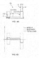
- Fig. 3A is a schematic view of the floating structure 1 along a section passing through the main column 2a and the side column 2b positioned diagonally thereto and Fig. 3B shows distributions of weights and buoyancies in the section.
- a short dashed line in Fig. 3B shows weights (downward loads) applied to portions shown in Fig. 3A .
- a dashed-dotted line in Fig. 3B shows buoyancies (upward loads) applied to the portions of the floating structure 1; the main column 2a with the lower hull 23 has buoyancy larger than the side column 2b.
- a solid line in Fig. 3B shows total loads as sums of the weights and buoyancies; slight loads are applied downward and upward on the main and side columns 2a and 2b, respectively, so that the total becomes zero into balancing of the floating structure 1 as a whole.
- Fig. 3C shows distributions of shearing forces and bending moments in the portions of the floating structure 1 due to the load distribution as mentioned in the above.
- the shearing forces (vertical forces) shown in Fig. 3C by a short dashed line appear as integration of the load curve shown by solid line in Fig. 3B ; the bending moments shown by a solid line in Fig. 3C appear integration of the shearing forces.
- the distribution of the bending moments becomes maximum on a left side position of the connecting body 3.
- a floating structure 101 of the first reference example comprises a main column 102a with no additional buoyancy body such as the lower hull 23 (see Fig. 3A ) so that there is no difference in volume of the submerged portions between the main and side columns 102a and 102b.
- buoyancies on the respective columns 102 are the same.
- it is generally conducted to pour ballast water W into the cavity 122 of the side column 102b.
- weights (downward loads) shown in a short dashed line become larger in the side column 102b shown left in the figure, by the ballast water W, than that of the side column 2b in the first embodiment (see Fig. 3B ).
- Buoyancies (upward load) shown in a dashed-dotted line are the same between the main and side columns 102a and 102b.
- Loads as sums of the weights and buoyancies as shown by a solid line in Fig. 4B are applied downward and upward in the main and side columns 102a and 102b, respectively, and absolute values thereof are larger than those of the first embodiment (see Fig. 3B ), respectively.
- the shearing forces as integration of the loads and bearing moments as integration of the shearing forces are larger than those of the first embodiment (see Fig. 3C ), respectively.
- the floating structure 1 of the first embodiment as shown in Figs. 1-3 is smaller in shearing force and bending moment generated in the connecting body 3 than the floating structure 101 of the first reference example as shown in Fig. 4 .
- required strengthening of the connecting body 3 is low, leading to reduction in weight of steel members used for the connecting body 3.
- the cavity 122 in the side column 102b requires a space for an adjustive ballast tank for balancing with the main column 102a to which the upper structure 4 is connected; by contrast, the floating structure 1 in the first embodiment requires no volume for an adjustive ballast tank so that the whole side column 2b can be made small in size, which also contributes to reduction in weight of the steel members used (though the main column 2a requires additional steel members for the lower hull 23, such added amount is fewer than the reduced amount in the side columns 2b).
- the floating structure 1 of the fist embodiment can be reduced in displacement by, for example, about 2% in comparison with the floating structure 101 of the first reference example.
- the machine room is arranged underneath the cavity 21 in the main column 2a for accommodation of the pump 26 and other equipment, which is because arrangement of the equipment in connection with the upper structure 4 (when the upper structure 4 is the wind turbine as shown in Fig. 1 , equipment for power conversion/delivery, a controller for the wind turbine 4 and the like) in a position as near as possible to the upper structure 4 is most effective in view of wiring and pipe laying and because arrangement of other equipment (the pump 26, a controller therefor and the like) is simplified by arranging them in a same position as much as possible.
- the first embodiment in which the main column 2a has the lower portion with the lower hull 23 contributing to enlargement of the cavity 21 by the cavity 24 is advantageous in that various equipment as mentioned in the above can be easily laid out there.
- the first embodiment is directed to the floating structure 1 with the plurality of columns 2 as vertically extending columnar buoyancy bodies and the connecting body 3 for interconnecting the columns 2 deployed horizontally, the upper structure (wind turbine) 4 being connected to the upper portion of at least one (main column 2a) of the columns 2, whereby the whole floating structure is supported on water, the floating structure 1 being constructed such that the column 2 (the main column 2a) among the columns 2 on which applied from the upper structure 4 is the load larger than that on each of the other columns 2 is larger in buoyancy than each of the other columns 2 (the side columns 2b); thus, imparting of the buoyancy to the main column 2a against the load from the upper structure 4 can correct any unbalance of load distribution between the columns 2 and reduce bending moments generated on the connecting body 3.
- the submerged portion of the main column 2a is larger in volume than that of each of the other columns 2 (side columns 2b) so that the buoyancy against the load from the upper structure 4 can be appropriately imparted to the main column 2a.
- the main column 2a has the lower portion with the lower hull 23 which has the inner cavity and projects horizontally from the main column 2a so that the lower hull 23 can increase water resistance against the vertical motions of the main column 2a to thereby attenuate the pitches.
- equipment in connection with the operation of the upper structure 4 or the floating structure 1 is arranged inside of the main column 2a, so that a wide space is available for accommodation of the various equipment, resulting in easiness in layout.
- load balance can be corrected while increase in size of the structure and strengthening of the structure are avoided as much as possible to suppress increase in construction cost.
- Fig. 5 shows a floating structure of a further embodiment (a second embodiment) according to the invention which is fundamentally similar in construction to the above-mentioned floating structure 1 (see Figs. 1 and 2 ) of the first embodiment.
- a floating structure 201 of the second embodiment is different in arrangement of columns from the first embodiment.
- the floating structure 201 of the second embodiment Among four columns 202 in the floating structure 201 of the second embodiment, three side columns 202b are arranged on respective apexes of an equilateral triangle in planar view and a main column 202a is positioned centrally of the triangle provided by the side columns 202b.
- the central main column 202a is connected with the surrounding side columns 202b through connecting bodies 203, and a wind turbine 4 as the upper structure is connected to an upper portion of the main column 202a.
- the floating structure illustrated is similar in arrangement to that disclosed in Patent Literature 2.
- the main column 202a has a lower portion with a lower hull 223 as a heave plate and also as a buoyancy body.
- each of the side columns 202b has a lower portion with a footing 225 merely serving as a heave plate.
- the main column 202a is larger in buoyancy, by the lower hull 223, than that of each of the side column 202b.
- the upper structure 4 is connected to the main column 202a as shown in Fig. 6A and thus a load applied downward on the central main column 202a is extremely larger than that on each of the left and right side columns 202b as shown by a short dashed line in Fig. 6B .
- the main column 202a has the lower portion with the lower hull 223 so that the buoyancy (the upward load) applied on the central main column 202a is larger than that on each of the left and right side columns 202b as shown by a dashed-dotted line in Fig. 6B .
- a solid line in Fig. 6B total loads of the weights and the buoyancies become slight and downward in the main column 202a and slight and upward in each of the side columns 202b.
- Fig. 7A shows an example of a floating structure (second reference example).
- the second reference example has a floating structure 301 similar in construction to that disclosed in Patent Literature 2 and is in common with the second embodiment (see Figs. 5 and 6A ) in that a main column 302a is installed centrally of three side columns 302b providing respective apexes of an equilateral triangle in planar view and is connected with the side columns 302b through connecting bodies 303.
- the second reference example is different from the second embodiment in that the main column 302a has no lower hull and each of the side columns 302b has a lower hull 323.
- downward load distribution is substantially similar to that of the second embodiment (see Fig. 6B ; however, the load on the main column 302a is slightly smaller by no provision of a lower hull; and by contraries, the load on each of the side columns 302b is larger by the provision of the lower hull 323). Meanwhile, buoyancies shown by a dashed-dotted line are small in the main column 302a and large in each of the side columns 302b. As a result, as shown by a solid line, the total loads become larger and downward in the central main column 302a and larger and upward in each of the left and right side columns 302b than those of the second embodiment.
- the floating structure 301 (see Fig. 7 ) of the second reference example requires no ballast water injected into the side columns 302b for balancing with the load of the upper structure 4; however, there still exists load unbalance between the main column 302a receiving a larger load from the upper structure 4 and each of the side columns 302b, which causes a larger shearing force or bending moment on the connecting bodies 303.
- the main column 202a to which the upper structure 4 is connected is provided with the lower hull 223 to increase buoyancy, thereby counteracting the load of the upper structure 4 to reduce load unbalance with the side columns 202b.
- Fig. 8 shows a floating structure of a still further embodiment (a third embodiment) of the invention in which an upper structure 5 connected to upper portions of the columns 402 constituting a floating structure 401 is not a wind turbine but a crane, which brings about difference in connecting bodies 403 and the like from that or those of the first or second embodiment (see Figs. 1 and 2 or Fig. 5 ) .
- upper and lower portions of the four columns 402 are interconnected through upper and lower connecting bodies 403a and 403b, respectively.
- the upper connecting body 403a provides a horizontal surface in the form of substantially quadrate in planar view on upper ends of the four columns 402 arranged at respective apexes of the quadrate provided by the upper connecting body 403a.
- the lower connecting bodies 403b interconnect lower ends of the columns 402 to provide sides of the quadrate.
- the crane as the upper structure 5 is placed on the surface provided by the upper connecting body 403a.
- none of the columns 402 is positioned just below a gravity center of the crane 5 as the upper structure, and a downward load by a weight of the crane 5 is applied to each of the four columns 402 through the upper connecting body 403a.
- the gravity center of the crane 5 is not aligned with the gravity center of all the four columns 402 in planar view and is in eccentricity.
- loads applied from the crane 5 to the four columns 402 are not equal, resulting in load deviation between the columns 402.
- the gravity center of the crane 5 deflects right in the figure relative to a gravity center of the four columns 402, resulting in application of an especially large downward load on the column 402 positioned at a right end in the figure.
- the lower hull 423 of the column 402 on the right in the figure is made larger than the lower hulls 423 of the other columns 402 to produce a large buoyancy on the column 402 on the right in the figure to thereby attain load balance between the columns 402.
- Fig. 9 shows a still further embodiment (a fourth embodiment) of a floating structure according to the invention.
- a floating structure 501 of the fourth embodiment has a connecting body 503 interconnecting columns 502 and provided with a buoyancy body 533 on a connection with the main column 502a.
- the buoyancy body 533 imparts buoyancy to the main column 502a on which the upper structure 4 is connected.
- the connecting body 503 interconnecting the columns 502 has the buoyancy body 533 on the connection with the column 502 (the main column 502a) on which larger load is applied downward from the upper structure 4 than each of the loads on the other columns 502 so that buoyancy can be imparted to the main column 502a without structural change of the main column 502a.
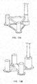
- Figs. 10A and 10B show still further embodiments of a floating structure according to the invention.
- the number of the columns may be three as shown in Fig. 10A or may be five or more (not shown).
- Appropriate changes may be conducted on arrangement of columns and construction of a connecting body depending on conditions such as kind and construction of an upper structure.
- a main column may be provided with a lower hull; as in the fourth embodiment (see Fig. 9 ), a connecting body may be provided with a buoyancy body; or as shown in Fig. 10B , a diameter of a column itself may be changed to impart a large buoyancy.
- a buoyancy body may be attached from outside to an existing column or connecting body to impart buoyancy; in this case, though steel members for construction of the floating structure cannot be reduced, it is effective, for example, upon exchange or addition of an upper structure after the floating structure is constructed.
- a floating structure of the invention may take various constructions as long as buoyancy can be properly imparted to a column.
- load balance can be corrected while increase in size of the structure and strengthening of the structure are avoided as much as possible to suppress increase in construction cost.
Abstract
Description
- The present invention relates to a floating structure with a structure supported on water by buoyancy such as an offshore power generation or storage facility.
- Recently, suspended type floating structures have been proposed as offshore facilities for wind or solar power generation and mining, manufacturing and storing of various resources.
- Such floating structures include various types such as "spar type", "semi-submersible type", "pontoon type" or "TLP (tension leg platform) type". Among them, the so-called "semi-submersible type" floating structure comprises a plurality of vertically extending columnar columns interconnected through a horizontally extending connecting body. Each of the columns is a buoyancy body with an inner cavity and is floatable on water by buoyancy. Such columns are deployed horizontally and are interconnected to increase a metacentric radius of the whole floating structure and thus ensure a sufficient restoring force.
- Each of the columns floating on water has a lower portion submerged (a submerged portion) and an upper portion above a water surface on which an upper structure is placeable. For example, when the semi-submersible floating structure as mentioned in the above is employed for an offshore wind power generation facility, a wind turbine as the upper structure is connected to an upper end of one of the columns.
- Technical literatures disclosing semi-submersible floating structures are, for example, undermentioned
Patent Literatures Patent Literature 1 comprises three columns on one of which (a tower support column) a wind turbine tower is placed. The remaining two columns serves not only to ensure a sufficient metacentric radius but also as stabilizing columns for adjustment of buoyancy balance. By contrast, a floating structure for an offshore facility disclosed inPatent Literature 2 comprises four columns, i.e., a centrally positioned central floating body and three outer floating bodies arranged therearound; a wind turbine is placed on an upper portion of the central floating body. -
- Patent Literature 1:
JP 2015-016860A - Patent Literature 2:
JP 2010-280301A - In the floating structure disclosed in
Patent Literature 1, the three columns are symmetrically arranged to provide respective apexes of an equilateral triangle in planar view. The wind turbine tower is placed on the tower support column which provides one of the apexes of the triangle. Thus, a weight on the tower support column is extremely larger than that on each of the other columns so that a gravity center of the whole floating structure including the wind turbine tower greatly deviates from a center of the equilateral triangle. Such deviation in gravity center may cause tilting of the floating structure; thus, it is generally conducted for prevention of such tilting that each column is provided with an adjustive ballast tank and the columns with no upper structure thereon are increased in weight by pumping water into the ballast tanks of the same, which requires that each column has a large volume for the adjustive ballast tank. Such countermeasure of pumping the ballast water in accordance with the weight of the tower support column to increase weights of the columns other than the tower support column may correct the position of the gravity center to assure horizontality of the whole floating structure; however, it may bring about non-uniformity of load distribution in the floating structure. As a result, a large bending moment may apply on beams interconnecting the columns, leading to necessity of strengthening the connecting structure between the columns to an extent endurable to such bending moment. In this manner, in the floating structure as disclosed inPatent Literature 1, many steel members are required both for the volume of the adjustive ballast tank and strengthening of the beams, disadvantageously leading to increase in construction cost. - In the floating structure for the offshore facility as disclosed in
Patent Literature 2, the central floating body is arranged centrally of an equilateral triangle provided by the outer three floating bodies in planar view and the wind turbine is placed on the central floating body so that no deviation in the gravity center occurs. However, such arrangement requires a structure connecting the outer floating bodies with the central floating body, leading to structural complication of the whole and resultant increase in construction cost just the same. Though there is no need of pumping water into adjustive ballast tanks to comply with any deviation in gravity center, non-uniformity in load may occur just the same between the central and outer floating bodies, resulting in required strengthening of the members connecting the central floating body with the outer floating bodies. - In view of the above, the invention has its object to provide a floating structure in which load balance can be corrected while increase in size of the structure and strengthening of the structure are avoided as much as possible to suppress increase in construction cost.
- The invention is directed to, in a floating structure with a plurality of columns as vertically extending columnar buoyancy bodies and a connecting body for interconnecting said columns deployed horizontally, an upper structure being connected to an upper portion of at least one of said columns, whereby the whole floating structure is supported on water, the floating structure constructed such that the column among said columns on which applied downwardly from said upper structure is a load larger than that on each of the other columns is larger in buoyancy than each of the other columns.
- In the floating structure of the invention, the column on which applied downwardly from said upper structure is the load larger than that on each of the other columns may have a submerged portion with a volume larger than that of a submerged portion of each of the other columns.
- In the floating structure of the invention, the column on which applied downwardly from said upper structure is the load larger than that on each of the other columns may be provided with a lower hull having an inner cavity and projecting horizontally from said column.
- In the floating structure of the invention, equipment for an operation of said upper structure or of said floating structure may be arranged in the column on which applied downwardly from the upper structure is the load larger than that on each of the other columns.
- In the floating structure of the invention, the connecting body for interconnecting said columns may have a connection provided with a buoyancy body and connected to the column on which applied downwardly from the upper structure is the load larger than that on each of the other columns.
- A floating structure according to the invention can exhibit an excellent effect that load balance can be corrected while increase in size of the structure and strengthening of the structure are avoided as much as possible to suppress increase in construction cost.
-
-
Fig. 1 is a perspective view showing a first embodiment of the invention; -
Fig. 2 is a sectional view showing the first embodiment of the invention and is a view looking in a direction of arrows II inFig. 1 ; -
Fig. 3A is a sectional view schematically showing the first embodiment of the invention; -
Fig. 3B is a graph showing a load distribution in the first embodiment of the invention; -
Fig. 3C is a graph showing shearing force and bending moment distributions in the first embodiment of the invention; -
Fig. 4A is a sectional view schematically showing a first reference example; -
Fig. 4B is a graph showing a load distribution in the first reference example of the invention; -
Fig. 4C is a graph showing shearing force and bending moment distributions in the first reference example of the invention; -
Fig. 5 is a perspective view showing a second embodiment of the invention; -
Fig. 6A is a front view schematically showing the second embodiment of the invention; -
Fig. 6B is a graph showing a load distribution in the second embodiment of the invention; -
Fig. 7A is a front view schematically showing a second reference example of the invention; -
Fig. 7B is a graph showing a load distribution in the second reference example of the invention; -
Fig. 8 is a perspective view showing a third embodiment of the invention; -
Fig. 9 is a perspective view showing a fourth embodiment of the invention; -
Fig. 10A is a perspective view showing another embodiment of the invention; and -
Fig. 10B is a perspective view showing still another embodiment of the invention. - Embodiments of the invention will be disclosed in conjunction with attached drawings.
-
Figs. 1 and2 show an embodiment (a first embodiment) of a floating structure according to the invention. As shown inFig. 1 , a semi-submersibletype floating structure 1 comprises vertically extending fourcolumnar columns 2 with lower portions interconnected by a horizontally extending connectingbody 3. The fourcolumns 2 are buoyancy bodies each with an inner cavity and are arranged to provide respective apexes of a square in planar view. Anupper structure 4 is connected to an upper portion of one (a main column) 2a of the fourcolumns 2. Thus, the fourcolumns 2 deployed horizontally support on water thewhole floating structure 1 to which theupper structure 4 is connected. - The
main column 2a and the threeside columns 2b are columnar bodies each generating buoyancy through at least partial submerging thereof, and haveinner cavities cavities corresponding column 2 and is at least partially utilizable as a ballast tank. The connectingbody 3 also has aninner cavity 31 and may be utilized as a buoyancy-generating buoyancy body or a ballast tank as needed. - The
main column 2a has a lower portion with alower hull 23 which projects horizontally and radially outwardly. Thelower hull 23 serves not only as a heave plate to increase water resistance against vertical movements of themain column 2a to thereby attenuate pitches but also to impart buoyancy to themain column 2a through aninner cavity 24 formed integrally with thecavity 21 in themain column 2a. In other words, thecavity 21 in themain column 2a has an increased diameter and an increased volume by thecavity 24 provided therebeneath. By contrast, each of the threeside columns 2b has a lower portion with a horizontally projectingfooting 25 which serves as a heave plate to attenuate pitches of theside column 2b but has no inner cavity and provides no buoyancy body. - The
lower hull 23 of themain column 2a and thefootings 25 of theside column 2b have mooring lines (not shown) connected thereto so that the floatingstructure 1 is moored through the mooring lines to water bottom and dwells in a predetermined water area. - As shown in
Fig. 2 , placed in thecavity 24 beneath thecavity 21 of themain column 2a is apump 26 communicated with thecavities 22 in theside columns 2b through awater feed pipe 32 in thecavity 31 of the connectingbody 3. Water pumped up from outside of the floatingstructure 1 by thepump 26 may be supplied to thecavities side columns body 3, respectively. Thecavities 21 and/or 24 in themain column 2a may also accommodate a machine or other room (not shown) provided with, for example, various controllers and power units as needed. - The
upper structure 4 is, for example, a wind turbine for wind power generation comprising abrace member 41, anacelle 42 andblades 43 as shown inFig. 1 . Thebrace member 41 is erected on themain column 2a through aconnection 27 on an upper end of themain column 2a. Thenacelle 42 is internally provided with a dynamo (not shown) to generate power through rotation of theblades 43. Theupper structure 4 is not limited to the wind power generation facility as illustrated. For example, it may be a solar power generation facility; otherwise assumable as theupper structure 4 are various facilities placeable on water such as observation, communication and mining facilities. - Next, mode of operation of the above-mentioned first embodiment will be described.
- When the floating
structure 1 is to be placed in position on an ocean or the like, the floatingstructure 1 and thebrace member 41, theblades 43 and the like of thewind turbine 4 as the upper structure are separately fabricated, for example, in a plant in a maritime area and then these are towed by a ship or the like to a sea area on which the floating structure is to be placed. Upon towing, it is preferable that the floatingstructure 1 has minimum submerged portions so as to suppress resistance from water and fuel consumption of the ship. Thus, a minimum amount of ballast water is poured into theinner cavities side columns body 3, and the towing is conducted in a state where a draft line is, for example, near an upper surface of thelower hull 23. - Upon arrival at the sea area on which the floating structure is to be placed, the
brace member 41 of thewind turbine 4 is erected on theconnection 27 on the upper portion of themain column 2a in the floatingstructure 1 and theblades 43 are attached to thenacelle 42. In this case, ballast water is properly supplied from thepump 26 in thecavity 24 underneath thecavity 21 in themain column 2a through thewater feed pipe 32 to thecavities side columns 2b and connectingbody 3 to thereby adjust the floatingstructure 1 in balance and stabilize the same in water, partly using thecavities cavities main column 2a andlower hull 23. Through such process, the floatingstructure 1 is placed horizontally as shown inFigs. 1 and2 to support thereon thewind turbine 4. In this case, the draft line is positioned vertically midway of thecolumns 2. - Among the
columns 2, themain column 2a with thewind turbine 4 connected to the upper portion thereof has extremely large weight applied thereon in comparison with each of theother side columns 2b. Meanwhile, by thelower hull 23 on the lower portion, themain column 2a has the submerged portion large in volume and thus large resultant buoyancy in comparison with each of theside columns 2b. Due to the buoyancy, themain column 2a resists the load applied by theupper structure 4 so that load disequilibrium of the same with theside columns 2b is corrected to keep balance of the whole floatingstructure 1. - Distributions of weights, buoyancies and resultant bending moments and the like in the floating
structure 1 as mentioned in the above will be explained in conjunction withFigs. 3A-3C .Fig. 3A is a schematic view of the floatingstructure 1 along a section passing through themain column 2a and theside column 2b positioned diagonally thereto andFig. 3B shows distributions of weights and buoyancies in the section. - A short dashed line in
Fig. 3B shows weights (downward loads) applied to portions shown inFig. 3A . Themain column 2a positioned right, which has thewind turbine 4 connected to the upper potion thereof, has larger load applied than theside column 2b positioned left. A dashed-dotted line inFig. 3B shows buoyancies (upward loads) applied to the portions of the floatingstructure 1; themain column 2a with thelower hull 23 has buoyancy larger than theside column 2b. A solid line inFig. 3B shows total loads as sums of the weights and buoyancies; slight loads are applied downward and upward on the main andside columns structure 1 as a whole. -
Fig. 3C shows distributions of shearing forces and bending moments in the portions of the floatingstructure 1 due to the load distribution as mentioned in the above. The shearing forces (vertical forces) shown inFig. 3C by a short dashed line appear as integration of the load curve shown by solid line inFig. 3B ; the bending moments shown by a solid line inFig. 3C appear integration of the shearing forces. In the embodiment illustrated, the distribution of the bending moments becomes maximum on a left side position of the connectingbody 3. - As a reference example, weight and other distributions in a typical conventional floating structure are shown in
Figs. 4A-4C . As shown inFig. 4A , a floatingstructure 101 of the first reference example comprises amain column 102a with no additional buoyancy body such as the lower hull 23 (seeFig. 3A ) so that there is no difference in volume of the submerged portions between the main andside columns side columns side columns structure 101 thus constructed, it is generally conducted to pour ballast water W into thecavity 122 of theside column 102b. - In the floating
structure 101 of the first reference example, as shown inFig. 4B , weights (downward loads) shown in a short dashed line become larger in theside column 102b shown left in the figure, by the ballast water W, than that of theside column 2b in the first embodiment (seeFig. 3B ). Buoyancies (upward load) shown in a dashed-dotted line are the same between the main andside columns - Loads as sums of the weights and buoyancies as shown by a solid line in
Fig. 4B are applied downward and upward in the main andside columns Fig. 3B ), respectively. Thus, as shown inFig. 4C , the shearing forces as integration of the loads and bearing moments as integration of the shearing forces are larger than those of the first embodiment (seeFig. 3C ), respectively. - As is clear from the above, the floating
structure 1 of the first embodiment as shown inFigs. 1-3 is smaller in shearing force and bending moment generated in the connectingbody 3 than the floatingstructure 101 of the first reference example as shown inFig. 4 . Thus, required strengthening of the connectingbody 3 is low, leading to reduction in weight of steel members used for the connectingbody 3. Moreover, in the floatingstructure 101 of the first reference example shown inFig. 4 , thecavity 122 in theside column 102b requires a space for an adjustive ballast tank for balancing with themain column 102a to which theupper structure 4 is connected; by contrast, the floatingstructure 1 in the first embodiment requires no volume for an adjustive ballast tank so that thewhole side column 2b can be made small in size, which also contributes to reduction in weight of the steel members used (though themain column 2a requires additional steel members for thelower hull 23, such added amount is fewer than the reduced amount in theside columns 2b). In provisional calculations by the applicant, the floatingstructure 1 of the fist embodiment can be reduced in displacement by, for example, about 2% in comparison with the floatingstructure 101 of the first reference example. - In the floating
structure 1 of the first embodiment, the machine room is arranged underneath thecavity 21 in themain column 2a for accommodation of thepump 26 and other equipment, which is because arrangement of the equipment in connection with the upper structure 4 (when theupper structure 4 is the wind turbine as shown inFig. 1 , equipment for power conversion/delivery, a controller for thewind turbine 4 and the like) in a position as near as possible to theupper structure 4 is most effective in view of wiring and pipe laying and because arrangement of other equipment (thepump 26, a controller therefor and the like) is simplified by arranging them in a same position as much as possible. In this connection, the first embodiment in which themain column 2a has the lower portion with thelower hull 23 contributing to enlargement of thecavity 21 by thecavity 24 is advantageous in that various equipment as mentioned in the above can be easily laid out there. - As is clear from the above, the first embodiment is directed to the floating
structure 1 with the plurality ofcolumns 2 as vertically extending columnar buoyancy bodies and the connectingbody 3 for interconnecting thecolumns 2 deployed horizontally, the upper structure (wind turbine) 4 being connected to the upper portion of at least one (main column 2a) of thecolumns 2, whereby the whole floating structure is supported on water, the floatingstructure 1 being constructed such that the column 2 (themain column 2a) among thecolumns 2 on which applied from theupper structure 4 is the load larger than that on each of theother columns 2 is larger in buoyancy than each of the other columns 2 (theside columns 2b); thus, imparting of the buoyancy to themain column 2a against the load from theupper structure 4 can correct any unbalance of load distribution between thecolumns 2 and reduce bending moments generated on the connectingbody 3. - In the first embodiment, the submerged portion of the
main column 2a is larger in volume than that of each of the other columns 2 (side columns 2b) so that the buoyancy against the load from theupper structure 4 can be appropriately imparted to themain column 2a. - In the first embodiment, the
main column 2a has the lower portion with thelower hull 23 which has the inner cavity and projects horizontally from themain column 2a so that thelower hull 23 can increase water resistance against the vertical motions of themain column 2a to thereby attenuate the pitches. - In the first embodiment, equipment in connection with the operation of the
upper structure 4 or the floatingstructure 1 is arranged inside of themain column 2a, so that a wide space is available for accommodation of the various equipment, resulting in easiness in layout. - Thus, according to the first embodiment, load balance can be corrected while increase in size of the structure and strengthening of the structure are avoided as much as possible to suppress increase in construction cost.
-
Fig. 5 shows a floating structure of a further embodiment (a second embodiment) according to the invention which is fundamentally similar in construction to the above-mentioned floating structure 1 (seeFigs. 1 and2 ) of the first embodiment. A floatingstructure 201 of the second embodiment is different in arrangement of columns from the first embodiment. - Among four
columns 202 in the floatingstructure 201 of the second embodiment, threeside columns 202b are arranged on respective apexes of an equilateral triangle in planar view and amain column 202a is positioned centrally of the triangle provided by theside columns 202b. The centralmain column 202a is connected with the surroundingside columns 202b through connectingbodies 203, and awind turbine 4 as the upper structure is connected to an upper portion of themain column 202a. Specifically, the floating structure illustrated is similar in arrangement to that disclosed inPatent Literature 2. - However, in the second embodiment, the
main column 202a has a lower portion with alower hull 223 as a heave plate and also as a buoyancy body. By contrast, each of theside columns 202b has a lower portion with afooting 225 merely serving as a heave plate. Thus, themain column 202a is larger in buoyancy, by thelower hull 223, than that of each of theside column 202b. - In the floating
structure 201 as mentioned in the above, which has the connectingbodies 203 interconnecting thecolumns 202 more complex than the connectingbody 3 of the first embodiment (seeFigs. 1 and2 ), mechanistic unbalance between the columns is properly corrected in comparison with the floating structure disclosed inPatent Literature 2. Explanation will be made thereon hereinafter. - First, in the floating
structure 201 of the second embodiment, theupper structure 4 is connected to themain column 202a as shown inFig. 6A and thus a load applied downward on the centralmain column 202a is extremely larger than that on each of the left andright side columns 202b as shown by a short dashed line inFig. 6B . Meanwhile, as shown inFig. 6A , themain column 202a has the lower portion with thelower hull 223 so that the buoyancy (the upward load) applied on the centralmain column 202a is larger than that on each of the left andright side columns 202b as shown by a dashed-dotted line inFig. 6B . As a result, as shown by a solid line inFig. 6B , total loads of the weights and the buoyancies become slight and downward in themain column 202a and slight and upward in each of theside columns 202b. - As a reference example for the second embodiment,
Fig. 7A shows an example of a floating structure (second reference example). The second reference example has a floatingstructure 301 similar in construction to that disclosed inPatent Literature 2 and is in common with the second embodiment (seeFigs. 5 and6A ) in that amain column 302a is installed centrally of threeside columns 302b providing respective apexes of an equilateral triangle in planar view and is connected with theside columns 302b through connectingbodies 303. However, the second reference example is different from the second embodiment in that themain column 302a has no lower hull and each of theside columns 302b has alower hull 323. - In such a construction, as shown by a short dashed line in
Fig. 7B , downward load distribution is substantially similar to that of the second embodiment (seeFig. 6B ; however, the load on themain column 302a is slightly smaller by no provision of a lower hull; and by contraries, the load on each of theside columns 302b is larger by the provision of the lower hull 323). Meanwhile, buoyancies shown by a dashed-dotted line are small in themain column 302a and large in each of theside columns 302b. As a result, as shown by a solid line, the total loads become larger and downward in the centralmain column 302a and larger and upward in each of the left andright side columns 302b than those of the second embodiment. - Specifically, unlike the floating structure 101 (see
Fig. 4 ) of the first reference example, the floating structure 301 (seeFig. 7 ) of the second reference example requires no ballast water injected into theside columns 302b for balancing with the load of theupper structure 4; however, there still exists load unbalance between themain column 302a receiving a larger load from theupper structure 4 and each of theside columns 302b, which causes a larger shearing force or bending moment on the connectingbodies 303. In the floatingstructure 201 of the second embodiment (seeFigs. 5 and6 ), themain column 202a to which theupper structure 4 is connected is provided with thelower hull 223 to increase buoyancy, thereby counteracting the load of theupper structure 4 to reduce load unbalance with theside columns 202b. - As a result, in the floating
structure 201 of the second embodiment, required strengthening of the connectingbodies 203 can be lowered to reduce a required amount of steel members for the connectingbodies 203. Though the large-volumelower hull 223 is required for the centralmain column 202a, no or a smaller lower hull is required for each of the surroundingside columns 202b. Thus, a required amount of steel members for the whole floatingstructure 201 can be reduced. - The other advantageous effects of the second embodiment are omitted since they are similar to those of the above-mentioned first embodiment (see
Figs. 1-3 ). Also in the second embodiment, load balance can be corrected while increase in size of the structure and strengthening of the structure are avoided as much as possible to suppress increase in construction cost. -
Fig. 8 shows a floating structure of a still further embodiment (a third embodiment) of the invention in which anupper structure 5 connected to upper portions of thecolumns 402 constituting a floatingstructure 401 is not a wind turbine but a crane, which brings about difference in connectingbodies 403 and the like from that or those of the first or second embodiment (seeFigs. 1 and2 orFig. 5 ) . - In the floating
structure 401 of the third embodiment, upper and lower portions of the fourcolumns 402 are interconnected through upper and lower connectingbodies body 403a provides a horizontal surface in the form of substantially quadrate in planar view on upper ends of the fourcolumns 402 arranged at respective apexes of the quadrate provided by the upper connectingbody 403a. The lower connectingbodies 403b interconnect lower ends of thecolumns 402 to provide sides of the quadrate. The crane as theupper structure 5 is placed on the surface provided by the upper connectingbody 403a. - In such a construction, none of the
columns 402 is positioned just below a gravity center of thecrane 5 as the upper structure, and a downward load by a weight of thecrane 5 is applied to each of the fourcolumns 402 through the upper connectingbody 403a. The gravity center of thecrane 5 is not aligned with the gravity center of all the fourcolumns 402 in planar view and is in eccentricity. Thus, loads applied from thecrane 5 to the fourcolumns 402 are not equal, resulting in load deviation between thecolumns 402. In a state shown inFig. 8 , the gravity center of thecrane 5 deflects right in the figure relative to a gravity center of the fourcolumns 402, resulting in application of an especially large downward load on thecolumn 402 positioned at a right end in the figure. Thus, in the floatingstructure 401 of the third embodiment, thelower hull 423 of thecolumn 402 on the right in the figure is made larger than thelower hulls 423 of theother columns 402 to produce a large buoyancy on thecolumn 402 on the right in the figure to thereby attain load balance between thecolumns 402. - The other advantageous effects of the third embodiment are omitted since they are similar to those of the above-mentioned first embodiment (see
Figs. 1-3 ). Also in the third embodiment, load balance can be corrected while increase in size of the structure and strengthening of the structure are avoided as much as possible to suppress increase in construction cost. -
Fig. 9 shows a still further embodiment (a fourth embodiment) of a floating structure according to the invention. Though similar in fundamental construction to the first embodiment (seeFigs. 1 and2 ), a floatingstructure 501 of the fourth embodiment has a connectingbody 503 interconnectingcolumns 502 and provided with abuoyancy body 533 on a connection with themain column 502a. Thebuoyancy body 533 imparts buoyancy to themain column 502a on which theupper structure 4 is connected. - In this case, in order to impart buoyancy to the
main column 502a, there is no need of adding structural changes on themain column 502a itself; only design change of the connectingbody 503 will suffice. Though themain column 502a in which various equipment may be placed may be low in freedom degree with respect to its inner structure and layout, the connectingbody 503 is meritorious in that provision of thebuoyancy body 533 thereon is less restrictive in design. - Thus, in the fourth embodiment, the connecting
body 503 interconnecting thecolumns 502 has thebuoyancy body 533 on the connection with the column 502 (themain column 502a) on which larger load is applied downward from theupper structure 4 than each of the loads on theother columns 502 so that buoyancy can be imparted to themain column 502a without structural change of themain column 502a. - The other advantageous effects of the fourth embodiment are omitted since they are similar to those of the above-mentioned first embodiment (see
Figs. 1-3 ). Also in the fourth embodiment, load balance can be corrected while increase in size of the structure and strengthening of the structure is avoided as much as possible to suppress increase in construction cost. -
Figs. 10A and 10B show still further embodiments of a floating structure according to the invention. The number of the columns may be three as shown inFig. 10A or may be five or more (not shown). Appropriate changes may be conducted on arrangement of columns and construction of a connecting body depending on conditions such as kind and construction of an upper structure. Moreover, as in the first embodiment (seeFigs. 1 and2 ), a main column may be provided with a lower hull; as in the fourth embodiment (seeFig. 9 ), a connecting body may be provided with a buoyancy body; or as shown inFig. 10B , a diameter of a column itself may be changed to impart a large buoyancy. Alternatively, though not shown, a buoyancy body may be attached from outside to an existing column or connecting body to impart buoyancy; in this case, though steel members for construction of the floating structure cannot be reduced, it is effective, for example, upon exchange or addition of an upper structure after the floating structure is constructed. A floating structure of the invention may take various constructions as long as buoyancy can be properly imparted to a column. - Also in each of such embodiments, load balance can be corrected while increase in size of the structure and strengthening of the structure are avoided as much as possible to suppress increase in construction cost.
- It is to be understood that a floating structure according to the invention is not limited to the above embodiments and that various changes and modifications may be made without departing from the scope of the invention.
-
- 1
- floating structure
- 2
- column
- 2a
- column (main column)
- 2b
- column (side column)
- 3
- connecting body
- 4
- upper structure (wind turbine)
- 5
- upper structure (crane)
- 23
- lower hull
- 201
- floating structure
- 202
- column
- 202a
- column (main column)
- 202b
- column (side column)
- 203
- connecting body
- 223
- lower hull
- 401
- floating structure
- 402
- column
- 403
- connecting body
- 403a
- connecting body (upper connecting body)
- 403b
- connecting body (lower connecting body)
- 423
- lower hull
- 501
- floating structure
- 502
- column
- 502a
- column (main column)
- 502b
- column (side column)
- 503
- connecting body
- 533
- buoyancy body
Claims (5)
- In a floating structure (1; 201; 401; 501) with a plurality of columns (2a, 2b; 202a, 202b; 402; 502a, 502b) as vertically extending columnar buoyancy bodies and a connecting body (3; 203; 403a, 403b; 503) for interconnecting said columns (2a, 2b; 202a, 202b; 402; 502a, 502b) deployed horizontally, an upper structure (4; 5) being connected to an upper portion of at least one (2a; 202a; 402; 502a) of said columns (2a, 2b; 202a, 202b; 402; 502a, 502b), whereby the whole floating structure (1; 201; 401; 501) is supported on water,
the floating structure (1; 201; 401; 501) constructed such that the column (2a; 202a; 402; 502a) among said columns (2a, 2b; 202a, 202b; 402; 502a, 502b) on which applied downwardly from said upper structure (4; 5) is a load larger than that on each of the other columns (2b; 202b; 402; 502b) is larger in buoyancy than each of the other columns (2b; 202b; 402; 502b). - The floating structure (1; 201; 401; 501) as claimed in claim 1 wherein the column (2a; 202a; 402; 502a) on which applied downwardly from said upper structure (4; 5) is the load larger than that on each of the other columns (2b; 202b; 402; 502b) has a submerged portion with a volume larger than that of a submerged portion of each of the other columns (2b; 202b; 402; 502b).
- The floating structure (1; 201; 401; 501) as claimed in claim 2 wherein the column (2a; 202a; 402; 502a) on which applied downwardly from said upper structure (4; 5) is the load larger than that on each of the other columns (2b; 202b; 402; 502b) has a lower portion with a lower hull (23; 223; 423) having an inner cavity (24) and projecting horizontally from said column (2a; 202a; 402; 502a).
- The floating structure (1; 201; 401; 501) as claimed in claim 2 or 3 wherein equipment (26) for an operation of said upper structure (4; 5) or of said floating structure (1; 201; 401; 501) is arranged in the column (2a; 202a; 402; 502a) on which applied downwardly from said upper structure (4; 5) is the load larger than that on each of the other columns (2b; 202b; 402; 502b).
- The floating structure (501) as claimed in claim 1 wherein the connecting body (503) for interconnecting said columns (502a, 502b) has a connection provided with a buoyancy body (533) and connected to the column (502a) on which applied downwardly from said upper structure (4) is the load larger than that on each of the other columns (502b).
Applications Claiming Priority (1)
| Application Number | Priority Date | Filing Date | Title |
|---|---|---|---|
| PCT/JP2016/084973 WO2018096650A1 (en) | 2016-11-25 | 2016-11-25 | Floating structure |
Publications (2)
| Publication Number | Publication Date |
|---|---|
| EP3546337A1 true EP3546337A1 (en) | 2019-10-02 |
| EP3546337A4 EP3546337A4 (en) | 2020-07-08 |
Family
ID=62195078
Family Applications (1)
| Application Number | Title | Priority Date | Filing Date |
|---|---|---|---|
| EP16922427.6A Pending EP3546337A4 (en) | 2016-11-25 | 2016-11-25 | Floating structure |
Country Status (5)
| Country | Link |
|---|---|
| EP (1) | EP3546337A4 (en) |
| JP (1) | JP6718518B2 (en) |
| KR (1) | KR102257418B1 (en) |
| CN (1) | CN109982923A (en) |
| WO (1) | WO2018096650A1 (en) |
Cited By (2)
| Publication number | Priority date | Publication date | Assignee | Title |
|---|---|---|---|---|
| CN113581395A (en) * | 2020-04-30 | 2021-11-02 | Bassoe科技公司 | Semi-submersible floating fan with T-shaped floating body |
| WO2022123130A1 (en) | 2020-12-10 | 2022-06-16 | Bourbon Offshore Gaia | Method for assembling a floating offshore wind farm |
Families Citing this family (8)
| Publication number | Priority date | Publication date | Assignee | Title |
|---|---|---|---|---|
| FR3090567B1 (en) * | 2018-12-24 | 2021-05-21 | Doris Eng | Naval platform supporting a wind turbine and associated naval installation |
| JP7234005B2 (en) * | 2019-03-29 | 2023-03-07 | ジャパンマリンユナイテッド株式会社 | FLOATING STRUCTURE, FLOATING WIND TURBINE SYSTEM AND METHOD FOR MANUFACTURING FLOATING STRUCTURE |
| CN110203342A (en) * | 2019-06-04 | 2019-09-06 | 上海交通大学 | More column floating type wind power generation devices |
| KR102093240B1 (en) | 2019-08-19 | 2020-03-25 | 박승균 | Multi-column structured and self weather vaning type offshore wind turbine support ship |
| FR3108953B1 (en) | 2020-04-06 | 2023-07-21 | Olivier Juin | SUPPORTING STRUCTURE FOR THE INSTALLATION OF WIND ENERGY CAPTURE MODULES |
| KR102624042B1 (en) * | 2020-10-30 | 2024-01-12 | 에이치디현대중공업 주식회사 | Floating offshore structures and floating offshore power plant having the same |
| CN114148462A (en) * | 2021-08-04 | 2022-03-08 | 中国华能集团清洁能源技术研究院有限公司 | Semi-submersible floating platform and eccentric fan system based on single point mooring |
| KR20230095361A (en) * | 2021-12-22 | 2023-06-29 | 주식회사 포스코 | Floating structure and wind power generator |
Citations (3)
| Publication number | Priority date | Publication date | Assignee | Title |
|---|---|---|---|---|
| US20120103244A1 (en) * | 2010-10-28 | 2012-05-03 | Jin Wang | Truss Cable Semi-submersible Floater for Offshore Wind Turbines and Construction Methods |
| WO2013040871A1 (en) * | 2011-09-22 | 2013-03-28 | Huang Canguang | Pre-stressed concrete floating platform for supporting offshore wind turbine and marine energy generator |
| GB2538329A (en) * | 2015-05-05 | 2016-11-16 | Oceanflow Dev Ltd | Platform and assembly solution for a floating offshore device |
Family Cites Families (6)
| Publication number | Priority date | Publication date | Assignee | Title |
|---|---|---|---|---|
| JP2001180584A (en) * | 1999-12-21 | 2001-07-03 | Sumitomo Heavy Ind Ltd | Semisubmersible type floating structure |
| JP4781954B2 (en) * | 2006-09-22 | 2011-09-28 | 三菱重工業株式会社 | Floating structure |
| CN107399411B (en) * | 2008-04-23 | 2019-06-04 | 原理动力有限公司 | The ballast control system of floating wind turbine platform and vertically-aligned adjusting method |
| JP2010280301A (en) | 2009-06-04 | 2010-12-16 | Shimizu Corp | Floating structural for offshore facility and method of constructing offshore facility |
| FR2967642B1 (en) * | 2010-11-22 | 2013-08-16 | Nass&Wind Ind | OFFSHORE WIND POWER DEVICE WITH PARTICULAR SEMI-SUBMERSIBLE FLOAT |
| EP2933181B1 (en) * | 2013-01-21 | 2017-11-22 | MHI Vestas Offshore Wind A/S | Method for maintaining floating wind-power generation device |
-
2016
- 2016-11-25 KR KR1020197015865A patent/KR102257418B1/en active IP Right Grant
- 2016-11-25 EP EP16922427.6A patent/EP3546337A4/en active Pending
- 2016-11-25 WO PCT/JP2016/084973 patent/WO2018096650A1/en unknown
- 2016-11-25 CN CN201680091124.2A patent/CN109982923A/en active Pending
- 2016-11-25 JP JP2018552350A patent/JP6718518B2/en active Active
Patent Citations (3)
| Publication number | Priority date | Publication date | Assignee | Title |
|---|---|---|---|---|
| US20120103244A1 (en) * | 2010-10-28 | 2012-05-03 | Jin Wang | Truss Cable Semi-submersible Floater for Offshore Wind Turbines and Construction Methods |
| WO2013040871A1 (en) * | 2011-09-22 | 2013-03-28 | Huang Canguang | Pre-stressed concrete floating platform for supporting offshore wind turbine and marine energy generator |
| GB2538329A (en) * | 2015-05-05 | 2016-11-16 | Oceanflow Dev Ltd | Platform and assembly solution for a floating offshore device |
Non-Patent Citations (1)
| Title |
|---|
| See also references of WO2018096650A1 * |
Cited By (4)
| Publication number | Priority date | Publication date | Assignee | Title |
|---|---|---|---|---|
| CN113581395A (en) * | 2020-04-30 | 2021-11-02 | Bassoe科技公司 | Semi-submersible floating fan with T-shaped floating body |
| WO2021219787A1 (en) * | 2020-04-30 | 2021-11-04 | Bassoe Technology Ab | Floating wind semi-submersible with t-shaped pontoon |
| WO2022123130A1 (en) | 2020-12-10 | 2022-06-16 | Bourbon Offshore Gaia | Method for assembling a floating offshore wind farm |
| FR3117553A1 (en) | 2020-12-10 | 2022-06-17 | Bourbon Offshore Gaia | Assembly process of a floating offshore wind farm |
Also Published As
| Publication number | Publication date |
|---|---|
| EP3546337A4 (en) | 2020-07-08 |
| JPWO2018096650A1 (en) | 2019-07-04 |
| KR20190072641A (en) | 2019-06-25 |
| CN109982923A (en) | 2019-07-05 |
| KR102257418B1 (en) | 2021-05-31 |
| JP6718518B2 (en) | 2020-07-08 |
| WO2018096650A1 (en) | 2018-05-31 |
Similar Documents
| Publication | Publication Date | Title |
|---|---|---|
| EP3546337A1 (en) | Floating structure | |
| CN110461702B (en) | Floating offshore platform | |
| KR102294285B1 (en) | Floating, semi-submersible wind turbine platform | |
| EP2993270B1 (en) | Submersible structure for actively supporting towers of generators and sub-stations or similar elements, in maritime facilities | |
| KR20210020160A (en) | Wind energy power plant and method of construction | |
| JP7014498B2 (en) | Floating wind turbine assemblies, as well as methods for mooring such floating wind turbine assemblies | |
| WO2013084632A1 (en) | Floating-body type wind power generating device, and floating installation method for same | |
| KR20110015418A (en) | Column-stabilized offshore platform with water-entrapment plates and asymmetric mooring system for support of offshore wind turbines | |
| KR20210010997A (en) | Wind turbine and method for installing wind turbine | |
| US20220234697A1 (en) | A floating structure and method of installation | |
| US20230407844A1 (en) | Wind turbine offshore support structure | |
| KR102523952B1 (en) | Tower-integrated offshore wind-force floating body and its manufacturing method | |
| AU2022361710A1 (en) | Semi-submersible floating platform for marine wind turbine | |
| WO2024030032A1 (en) | Mooring system | |
| WO2023135166A1 (en) | Hull structure for a semi-submersible wind power turbine platform |
Legal Events
| Date | Code | Title | Description |
|---|---|---|---|
| STAA | Information on the status of an ep patent application or granted ep patent |
Free format text: STATUS: THE INTERNATIONAL PUBLICATION HAS BEEN MADE |
|
| PUAI | Public reference made under article 153(3) epc to a published international application that has entered the european phase |
Free format text: ORIGINAL CODE: 0009012 |
|
| STAA | Information on the status of an ep patent application or granted ep patent |
Free format text: STATUS: REQUEST FOR EXAMINATION WAS MADE |
|
| 17P | Request for examination filed |
Effective date: 20190523 |
|
| AK | Designated contracting states |
Kind code of ref document: A1 Designated state(s): AL AT BE BG CH CY CZ DE DK EE ES FI FR GB GR HR HU IE IS IT LI LT LU LV MC MK MT NL NO PL PT RO RS SE SI SK SM TR |
|
| AX | Request for extension of the european patent |
Extension state: BA ME |
|
| DAV | Request for validation of the european patent (deleted) | ||
| DAX | Request for extension of the european patent (deleted) | ||
| A4 | Supplementary search report drawn up and despatched |
Effective date: 20200605 |
|
| RIC1 | Information provided on ipc code assigned before grant |
Ipc: B63B 35/44 20060101AFI20200529BHEP Ipc: B63B 1/10 20060101ALI20200529BHEP |
|
| STAA | Information on the status of an ep patent application or granted ep patent |
Free format text: STATUS: EXAMINATION IS IN PROGRESS |
|
| 17Q | First examination report despatched |
Effective date: 20220401 |