EP3546333A1 - Power unit - Google Patents
Power unit Download PDFInfo
- Publication number
- EP3546333A1 EP3546333A1 EP19163339.5A EP19163339A EP3546333A1 EP 3546333 A1 EP3546333 A1 EP 3546333A1 EP 19163339 A EP19163339 A EP 19163339A EP 3546333 A1 EP3546333 A1 EP 3546333A1
- Authority
- EP
- European Patent Office
- Prior art keywords
- drive shaft
- detecting sensor
- speed detecting
- transmission case
- power unit
- Prior art date
- Legal status (The legal status is an assumption and is not a legal conclusion. Google has not performed a legal analysis and makes no representation as to the accuracy of the status listed.)
- Granted
Links
Images


Classifications
-
- B—PERFORMING OPERATIONS; TRANSPORTING
- B62—LAND VEHICLES FOR TRAVELLING OTHERWISE THAN ON RAILS
- B62M—RIDER PROPULSION OF WHEELED VEHICLES OR SLEDGES; POWERED PROPULSION OF SLEDGES OR SINGLE-TRACK CYCLES; TRANSMISSIONS SPECIALLY ADAPTED FOR SUCH VEHICLES
- B62M7/00—Motorcycles characterised by position of motor or engine
- B62M7/12—Motorcycles characterised by position of motor or engine with the engine beside or within the driven wheel
-
- B—PERFORMING OPERATIONS; TRANSPORTING
- B62—LAND VEHICLES FOR TRAVELLING OTHERWISE THAN ON RAILS
- B62K—CYCLES; CYCLE FRAMES; CYCLE STEERING DEVICES; RIDER-OPERATED TERMINAL CONTROLS SPECIALLY ADAPTED FOR CYCLES; CYCLE AXLE SUSPENSIONS; CYCLE SIDECARS, FORECARS, OR THE LIKE
- B62K11/00—Motorcycles, engine-assisted cycles or motor scooters with one or two wheels
- B62K11/02—Frames
- B62K11/10—Frames characterised by the engine being over or beside driven rear wheel
-
- G—PHYSICS
- G01—MEASURING; TESTING
- G01P—MEASURING LINEAR OR ANGULAR SPEED, ACCELERATION, DECELERATION, OR SHOCK; INDICATING PRESENCE, ABSENCE, OR DIRECTION, OF MOVEMENT
- G01P1/00—Details of instruments
-
- B—PERFORMING OPERATIONS; TRANSPORTING
- B60—VEHICLES IN GENERAL
- B60Y—INDEXING SCHEME RELATING TO ASPECTS CROSS-CUTTING VEHICLE TECHNOLOGY
- B60Y2200/00—Type of vehicle
- B60Y2200/10—Road Vehicles
- B60Y2200/12—Motorcycles, Trikes; Quads; Scooters
- B60Y2200/126—Scooters
-
- F—MECHANICAL ENGINEERING; LIGHTING; HEATING; WEAPONS; BLASTING
- F16—ENGINEERING ELEMENTS AND UNITS; GENERAL MEASURES FOR PRODUCING AND MAINTAINING EFFECTIVE FUNCTIONING OF MACHINES OR INSTALLATIONS; THERMAL INSULATION IN GENERAL
- F16H—GEARING
- F16H57/00—General details of gearing
- F16H57/02—Gearboxes; Mounting gearing therein
- F16H2057/0203—Gearboxes; Mounting gearing therein the gearbox is associated or combined with a crank case of an engine
-
- F—MECHANICAL ENGINEERING; LIGHTING; HEATING; WEAPONS; BLASTING
- F16—ENGINEERING ELEMENTS AND UNITS; GENERAL MEASURES FOR PRODUCING AND MAINTAINING EFFECTIVE FUNCTIONING OF MACHINES OR INSTALLATIONS; THERMAL INSULATION IN GENERAL
- F16H—GEARING
- F16H57/00—General details of gearing
- F16H57/02—Gearboxes; Mounting gearing therein
- F16H57/027—Gearboxes; Mounting gearing therein characterised by means for venting gearboxes, e.g. air breathers
Definitions
- the present invention relates to a power unit comprising: a gear mounted on a drive shaft of a rear wheel in a transmission case so as to rotate integrally with the drive shaft; and a speed detecting sensor having a detection tip end that faces the gear, having a coupling end coupled to a harness outside the transmission case, and detecting a rotation speed of the drive shaft.
- Patent Document 1 discloses a speed detecting sensor that has a coupling end coupled to a harness outside a transmission case and detects a rotation speed of a drive shaft.
- the transmission case has an outer surface on which a protection wall that projects at a position displaced rearward about an axis from the coupling end is integrally formed.
- the protection wall has a curved surface that curves so as to recede from the drive shaft as approaching the speed detecting sensor about the axis from a lower side of the drive shaft. Therefore, a U-shaped lock can avoid the coupling end of the speed detecting sensor by tracing the curved surface of the protection wall. Thus, even when a two-wheeled motor vehicle is moved when the U-shaped lock is mounted, a collision between the U-shaped lock and the speed detecting sensor can be avoided.
- the speed detecting sensor is reliably protected.
- Patent Document 1 Japanese Patent Application Laid-open No. 2010-76604
- the present invention has been made in view of the actual situation described above, and it is an object of the present invention to provide a power unit that ensures achieving a downsized protection wall that protects a coupling end of a speed detecting sensor.
- a power unit comprising: a gear mounted on a drive shaft of a rear wheel in a transmission case so as to rotate integrally with the drive shaft; and a speed detecting sensor having a detection tip end that faces the gear, having a coupling end coupled to a harness outside the transmission case, and detecting a rotation speed of the drive shaft, characterized in that a protection wall projects from an outer surface of the transmission case at a position displaced from the coupling end in an axial direction of the drive shaft.
- the protection wall is positioned rearward of a rear end of the speed detecting sensor about an axis of the drive shaft.
- the power unit further comprising a sensor cover mounted on the outer surface of the transmission case, and housing the coupling end and the protection wall.
- the harness in addition to any one of the first aspect to the third aspect, extends upward from an upper end of the coupling end.
- the transmission case has a fastening hole formed at a position displaced from the coupling end in the axial direction of the drive shaft, the fastening hole receiving a fastening bolt of the speed detecting sensor.
- the power unit further comprising a breather tube drawn out from the outer surface of transmission case in front of the speed detecting sensor so as to extend forward.
- the breather tube is disposed at a position displaced from the harness in the axial direction of the drive shaft.
- the U-shaped lock collides with the protection wall at the position displaced from the coupling end of the speed detecting sensor, and thus, a collision between the U-shaped lock and the speed detecting sensor can be avoided.
- the speed detecting sensor is reliably protected.
- the protection wall only receives the U-shaped lock about the axis of the drive shaft, thereby ensuring the downsized protection wall.
- the U-shaped lock collides with the protection wall prior to the speed detecting sensor, thereby ensuring reliably protecting the speed detecting sensor.
- the sensor cover covers the coupling end of the speed detecting sensor, the sensor cover can protect the speed detecting sensor from, for example, gravels splashed.
- the sensor cover covers over the speed detecting sensor and the protection wall, designability of a saddle riding vehicle in which the power unit is incorporated can be properly maintained.
- the harness extends upward from the coupling end of the speed detecting sensor, the interference between the protection wall and the harness can be avoided.
- the protection wall projects from the outer surface of the transmission case at the position displaced from the coupling end in the axial direction of the drive shaft.
- the protection wall can approach close to the coupling end of the speed detecting sensor as close as possible. An arrangement space can be reduced.
- the fastening bolt can be protected together with the speed detecting sensor from the U-shaped lock.
- the breather tube can be disposed without interfering with the speed detecting sensor and the protection wall.
- the breather tube can be disposed without interfering with the harness of the speed detecting sensor.
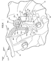
- FIG. 1 schematically illustrates a scooter type two-wheeled motor vehicle according to one embodiment of a saddle riding vehicle.
- a two-wheeled motor vehicle 11 includes a body frame 12 and a vehicle body cover 13 mounted on the body frame 12.
- the body frame 12 includes a head tube 14, a down tube 15, and a pair of right and left side frames 16.
- the down tube 15 extends downward from the head tube 14.
- the side frames 16 extend rearward from a lower end of the down tube 15.
- the head tube 14 steerably supports a front fork 17 that supports a front wheel WF rotatably about an axle shaft, and a rod-shaped steering handlebar 18.
- the side frame 16 has a down frame portion 16a, a lower frame portion 16b, and a seat rail portion 16c.
- the down frame portion 16a extends downward from a lower end of the down tube 15.
- the lower frame portion 16b extends in parallel with a ground from a rear end of the down frame portion 16a.
- the seat rail portion 16c extends upward to a rear from a rear end of the lower frame portion 16b to be disposed above a rear wheel WR. Above the seat rail portion 16c, an occupant seat 19 is mounted on the vehicle body cover 13.
- the vehicle body cover 13 includes a front cover 21, a leg shield 22, and a step floor 23.
- the front cover 21 covers the head tube 14 from the front.
- the leg shield 22 is continuous with the front cover 21.
- the step floor 23 is continuous with a lower end of the leg shield 22 to be disposed above the lower frame portion 16b between the occupant seat 19 and the front wheel WF. An occupant seating on the occupant seat 19 can put his/her feet on the step floor 23.
- the lower frame portion 16b supports a fuel tank 24 storing a fuel under the step floor 23.
- a unit swing-type power unit 25 is disposed in a space underneath the seat rail portion 16c.
- the power unit 25 is coupled to a bracket 26 swingably in a vertical direction via a link 27.
- the bracket 26 is combined to the rear end of the lower frame portion 16b.
- the power unit 25 has a rear end that rotatably supports the rear wheel WR about an axis Hx of a horizontal axis.
- the power unit 25 includes an internal combustion engine 28 and a transmission device 29.
- the internal combustion engine 28 generates a power based on a fuel supplied from the fuel tank 24.
- the transmission device 29 is coupled to the internal combustion engine 28 and transmits the power of the internal combustion engine 28 to the rear wheel WR at a gear ratio that linearly changes.
- the transmission case 32 of the transmission device 29 is combined to the crankcase 31 of the internal combustion engine 28.
- a rear cushion unit 33 is disposed between the seat rail portion 16c and the power unit 25 at a position apart from the link 27 and the bracket 26.
- the power unit 25 functions as a suspension device that swingably couples the rear wheel WR to the body frame 12.
- the rear wheel WR includes a hub 35, a rim 37, and a plurality of spokes 38a, 38b.
- the hub 35 is combined to the drive shaft 34 and expands rearward with respect to the transmission case 32.
- the rim 37 is disposed coaxially with the hub 35 and supports a tire 36 made of rubber.
- the plurality of spokes 38a, 38b couple the rim 37 to the hub 35.
- the spokes 38a, 38b form pairs of a front spoke 38a and a rear spoke 38b.
- the front spoke 38a inclines in a direction of forward movement at a prescribed angle ⁇ with respect to a diameter line RL about the drive shaft 34.
- the rear spoke 38b inclines in a retreat direction at a prescribed angle ⁇ with respect to the diameter line RL about the drive shaft 34.
- the hub 35, rim 37, and spokes 38a, 38b are integrally molded from a metallic material, such as aluminum.
- the internal combustion engine 28 includes a crankcase 31, a cylinder block 41, a cylinder head 42, and a head cover 43.
- the crankcase 31 supports a crankshaft (described below) rotatably about a rotation axis Rx extending in parallel with the axis Hx of the rear wheel WR.
- the cylinder block 41 is combined to the crankcase 31.
- the cylinder head 42 is combined to the cylinder block 41.
- the head cover 43 is combined to the cylinder head 42.
- An intake device 44 and an exhaust device 45 are coupled to the cylinder head 42.
- the intake device 44 includes an air cleaner 46 and a throttle body 47.
- the air cleaner 46 is supported by the transmission case 32 and suctions and purifies an external air.
- the throttle body 47 couples the air cleaner 46 to the cylinder head 42.
- the cylinder head 42 has an upper wall on which a fuel injection device 48 is mounted.
- the exhaust device 45 includes an exhaust pipe 49 and an exhaust muffler (not illustrated).
- the exhaust pipe 49 extends rearward through underneath the internal combustion engine 28 from a lower wall of the cylinder head 42.
- the exhaust muffler is coupled to a downstream end of the exhaust pipe 49 to be coupled to the crankcase 31.
- the crankcase 31 is divided into a first case half body 31a and a second case half body 31b.
- the first case half body 31a and the second case half body 31b collaborate to partition a crank chamber 51.
- the crank chamber 51 houses a crank of a crankshaft 52.
- a bearing 53a that rotatably supports the crankshaft 52 is assembled to the first case half body 31a.
- a bearing 53b that rotatably supports the crankshaft 52 is assembled to the second case half body 31b.
- a cylinder bore 54 is partitioned.
- a piston 55 is engaged slidably along a cylinder axis C.
- the piston 55 is coupled to the crank of the crankshaft 52 with a connecting rod 56.
- a linear reciprocation motion of the piston 55 is transformed into a rotational motion of the crankshaft 52.
- the cylinder axis C inclines slightly upward to a front from the horizon.
- a combustion chamber 57 is partitioned between the piston 55 and the cylinder head 42.
- An air-fuel mixture is introduced into the combustion chamber 57 via the intake device 44.
- An exhaust gas inside the combustion chamber 57 is discharged via the exhaust device 45.
- the crankshaft 52 has one end to which an AC generator (ACG) 58 is coupled.
- the AC generator 58 includes a pipe shaped rotor 58a and a stator 58b.
- the rotor 58a is secured to the one end of the crankshaft 52 projecting from an outer surface of the first case half body 31a.
- the stator 58b is disposed around the crankshaft 52 surrounded by the rotor 58a.
- the stator 58b is configured of a plurality of coils individually wound around a stator core.
- the stator 58b is secured to a support plate 59 fastened to the first case half body 31a.
- the AC generator 58 generates electricity in response to relative rotation of the rotor 58a and the stator 58b.
- the transmission device 29 includes a belt type continuously variable transmission (hereinafter referred to as "transmission") 65 and a deceleration gear mechanism 67.
- the transmission 65 includes a drive pulley 61 and a V belt 64 to steplessly shift a rotative power transmitted from the crankshaft 52.
- the drive pulley 61 is housed within the transmission case 32 and mounted to the crankshaft 52 projecting from an outer surface of the second case half body 31b.
- the V belt 64 is wound around a driven pulley 63 mounted to a driven shaft 62.
- the deceleration gear mechanism 67 is housed within the transmission case 32, and decelerates and transmits the rotative power of the transmission 65 to the drive shaft 34 of the rear wheel WR.
- the transmission case 32 includes a case entity 68, a case cover 71, and a gear cover 73.
- the case entity 68 is continuous with the second case half body 31b of the crankcase 31.
- the case cover 71 is fastened to the case entity 68 and partitions a transmission chamber 69 that houses the transmission 65 between the case cover 71 and the case entity 68.
- the gear cover 73 is fastened to the case entity 68 and partitions a gear chamber 72 between the gear cover 73 and the case entity 68.
- the gear chamber 72 houses the deceleration gear mechanism 67.
- the drive pulley 61 includes a pulley half body 74 and a pulley half body 75.
- the pulley half body 74 is secured coaxially to the crankshaft 52 and has a conical-shaped inward surface.
- the pulley half body 75 is supported coaxially to the crankshaft 52 movably in an axial direction of the crankshaft 52 and has a conical-shaped inward surface that is caused to face the inward surface of the pulley half body 74.
- the V belt 64 is wound around between the inward surface of the pulley half body 74 and the inward surface of the pulley half body 75.
- the pulley half body 75 is disposed between the second case half body 31b of the crankcase 31 and the pulley half body 74.
- a cam plate 77 is secured to the pulley half body 75.
- the cam plate 77 is caused to face a weight holding member 76 secured to the crankshaft 52 in a non-displaceable manner in the axial direction.
- a centrifugal weight 78 is interposed between the cam plate 77 and the weight holding member 76.
- the cam plate 77 recedes from the pulley half body 74 as receding from the rotation axis Rx of the crankshaft 52 in a centrifugal direction. The centrifugal force is generated in the centrifugal weight 78 in association with a rotation of the crankshaft 52.
- the pulley half body 75 As the centrifugal weight 78 displaces in the centrifugal direction while the centrifugal weight 78 rolling contacts the cam plate 77, the pulley half body 75 is driven toward the pulley half body 74. Thus, the pulley half body 75 moves toward the pulley half body 74 in the axial direction in response to the rotation of the crankshaft 52, and thus, a winding radius of the V belt 64 changes.
- the driven pulley 63 includes an inner pipe 79, a pulley half body 81, an outer pipe 82, and a pulley half body 83.
- the inner pipe 79 has a cylindrical shape coaxial with the driven shaft 62 to be coaxially mounted on the driven shaft 62.
- the pulley half body 81 is secured to the inner pipe 79 so as to be coaxial with the inner pipe 79.
- the outer pipe 82 has a cylindrical shape coaxial with the driven shaft 62 to be coaxially mounted on the inner pipe 79.
- the pulley half body 83 is secured to the outer pipe 82 so as to be coaxial with the outer pipe 82, and has an inward surface that faces an inward surface of the pulley half body 81.
- the V belt 64 is wound around between the inward surface of the pulley half body 81 and the inward surface of the pulley half body 83.
- the inner pipe 79 is relatively rotatably supported by the driven shaft 62.
- the outer pipe 82 is supported relatively rotatably and relatively displaceably in the axial direction by the inner pipe 79.
- the pulley half body 83 approaches the pulley half body 81 and recedes from the pulley half body 81.
- the centrifugal clutch 84 On the driven shaft 62, a centrifugal clutch 84 is mounted.
- the centrifugal clutch 84 includes a clutch plate 84a and an outer plate 84b.
- the clutch plate 84a is secured to the inner pipe 79.
- the outer plate 84b is secured to the driven shaft 62 and caused to face the clutch plate 84a.
- a coiled spring 85 is disposed between the clutch plate 84a and the pulley half body 83.
- the coiled spring 85 provides an elastic force to press the pulley half body 83 toward the pulley half body 81.
- the deceleration gear mechanism 67 includes a drive gear 86, a final gear 87, and transmission gears 88a, 88b.
- the drive gear 86 is secured to the driven shaft 62 protruding to the gear chamber 72.
- the final gear 87 is secured to the drive shaft 34 of the rear wheel WR to rotate integrally with the drive shaft 34.
- the transmission gears 88a, 88b are disposed between the drive gear 86 and the final gear 87.
- the transmission gears 88a, 88b are secured to a shared intermediate shaft 89.
- the drive gear 86 engages with the transmission gear 88a, and the final gear 87 engages with the transmission gear 88b.
- a speed detecting sensor 91 is mounted on the transmission case 32.
- the speed detecting sensor 91 faces the final gear 87 with a detection tip end 91a entering the gear chamber 72 to detect a rotation speed of the drive shaft 34.
- the speed detecting sensor 91 has a coupling end 91b coupled to a harness 92 outside the transmission case 32.
- the coupling end 91b projects outside the transmission case 32 by standing upright from an outer surface of the transmission case 32.
- the speed detecting sensor 91 it is used one that uses a magnetoresistive element that transforms a magnitude of a magnetic force into an electrical signal according, for example, to presence/absence of teeth of a magnetic material.
- a detection signal of the speed detecting sensor 91 is supplied to, for example, an electronic control unit (ECU), which is not illustrated, through the harness 92.
- ECU electronice control unit
- the harness 92 has a first linear region 92a, a folded back region 92b, a second linear region 92c, and a non-restrained region 92d.
- the first linear region 92a extends upward from an upper end of the coupling end 91b to recede from the outer surface of the transmission case 32.
- the folded back region 92b is continuous with the first linear region 92a and curves so as to be folded back downward toward the outer surface of the transmission case 32.
- the second linear region 92c is continuous with the folded back region 92b and approach the outer surface of the transmission case 32 along a side surface of the coupling end 91b.
- the non-restrained region 92d is continuous with the second linear region 92c and extends forward along the outer surface of the transmission case 32.
- the second linear region 92c is fastened to the side surface of the coupling end 91b with a band 93 made of resin.
- a configuration of the harness 92 is restrained by the band 93.
- the gear cover 73 of the transmission case 32 has a fastening hole 95 formed at a position displaced from the coupling end 91b in the axial direction of the drive shaft 34.
- the fastening hole 95 receives a fastening bolt 94 of the speed detecting sensor 91.
- a mounting piece 96 that is stacked over an outer surface of the gear cover 73 is secured to the speed detecting sensor 91.
- the mounting piece 96 has a through hole 97 formed to receive the fastening bolt 94 coaxially to the fastening hole 95.
- the fastening bolt 94 exits the through hole 97 to be screwed into the fastening hole 95.
- the speed detecting sensor 91 is secured to the gear cover 73 of the transmission case 32 with the fastening bolt 94.
- the case entity 68 of the transmission case 32 has a protection wall 98 integrally formed at a position displaced from the coupling end 91b of the speed detecting sensor 91 in the axial direction of the drive shaft 34.
- the protection wall 98 projects from the outer surface of the transmission case 32.
- the fastening hole 95, speed detecting sensor 91, and protection wall 98 are collocated in this order from a side (inner side of a vehicle) of the hub 35 of the rear wheel WR in the axial direction of the drive shaft 34.
- a bracket 99 is integrally formed.
- the bracket 99 supports a lower end of the rear cushion unit 33 rotatably about a rotation axis parallel to an axial center of the drive shaft 34.
- the protection wall 98 is disposed at a rear of the bracket 99. As illustrated in FIG. 5 , the protection wall 98 includes a columnar shaped base 98a, a wall body 98b, and a reinforcing wall 98c.
- the base 98a is continuous with the case entity 68 and has an axis Cx parallel to an axial center of the drive shaft 34.
- the wall body 98b is integrated with a rear end of the base 98a while being continuous with the case entity 68 and specifies an upright surface 101 in a planar surface parallel to the axial center of the drive shaft 34.
- the reinforcing wall 98c extends along a virtual plane perpendicular to the axial center of the drive shaft 34 while being continuous with an inward surface of the base 98a and is integrated with the wall body 98b on a ridgeline 102 standing upright from the outer surface of the transmission case 32.
- the ridgeline 102 of the wall body 98b and the reinforcing wall 98c has a height as high as the coupling end 91b of the speed detecting sensor 91.
- the protection wall 98 has a rear end (virtual plane PP including the upright surface 101) that is positioned at a rear with respect to a rear end of the speed detecting sensor 91 about the axis of the drive shaft 34.
- a screw hole 103 coaxial with the axis Cx is drilled on the base 98a of the protection wall 98. In the screw hole 103, a thread groove for a female screw is threaded.
- a sensor cover 105 that houses the coupling end 91b of the speed detecting sensor 91 and the protection wall 98 is mounted on the outer surface of the transmission case 32.
- the sensor cover 105 is secured to the transmission case 32 with a screw member 106.
- the screw member 106 is screwed into the screw hole 103 formed in the base 98a of the protection wall 98 as described above.
- the sensor cover 105 is molded from, for example, a resin material.
- a breather tube 107 is mounted on the gear cover 73 of the transmission case 32.
- the breather tube 107 is drawn out from the outer surface of the transmission case 32 in front of the speed detecting sensor 91 and extends forward.
- the breather tube 107 is disposed at a position displaced from the harness 92 in the axial direction of the drive shaft 34.
- the breather tube 107 extends forward in parallel with the non-restrained region 92d of the harness 92.
- the drive shaft 34 of the rear wheel WR rotates.
- the centrifugal weight 78 displaces radially outward and the winding radius of the V belt 64 increases.
- the winding radius of the driven pulley 63 decreases according to the winding radius of the drive pulley 61.
- the transmission 65 steplessly shifts a gear ratio.
- the speed detecting sensor 91 detects a rotation speed of the final gear 87 according to the presence/absence of the teeth of the final gear 87. Since the rear wheel WR and the final gear 87 are secured to the drive shaft 34 in a relatively unrotatable manner, the rotation speed of the final gear 87 reflects a travelling speed of the two-wheeled motor vehicle 11. Thus, the speed detecting sensor 91 detects the travelling speed of the two-wheeled motor vehicle 11. The travelling speed is, for example, displayed on a speedometer.
- the shaft body 108 of the U-shaped lock When the shaft body 108 of the U-shaped lock is installed in a front side of the front spoke 38a in the direction of forward movement about the drive shaft 34, the shaft body 108 of the U-shaped lock is interposed between the front spoke 38a and the upright surface 101 of the wall body 98b because an outer periphery of the hub 35 and the front spoke 38a intersect at an acute angle. Therefore, a movement of the U-shaped lock is restrained.
- the speed detecting sensor 91 is reliably protected.
- the protection wall 98 only receives the U-shaped lock about the axis of the drive shaft 34, and thus, the protection wall 98 is downsized.
- the wall body 98b of the protection wall 98 is positioned at a rear with respect to a rear end of the speed detecting sensor 91 about the axis of the drive shaft 34, even though the rear wheel WR rotates when the U-shaped lock is mounted, the U-shaped lock collides with the protection wall 98 prior to the speed detecting sensor 91, thereby reliably protecting the speed detecting sensor 91.
- the sensor cover 105 which houses the coupling end 91b of the speed detecting sensor 91 and the protection wall 98, is mounted on the outer surface of the transmission case 32. Since the sensor cover 105 covers the coupling end 91b of the speed detecting sensor 91, the sensor cover 105 protects the speed detecting sensor 91 from, for example, gravels splashed. In addition, since the sensor cover 105 covers over the speed detecting sensor 91 and the protection wall 98, designability of the two-wheeled motor vehicle 11 in which the power unit 25 is incorporated is properly maintained.
- the first linear region 92a of the harness 92 extends upward from the upper end of the coupling end 91b of the speed detecting sensor 91 standing upright from the outer surface of the transmission case 32.
- the harness 92 thus extending upward from the coupling end 91b of the speed detecting sensor 91 avoids the interference between the protection wall 98 and the harness 92.
- the protection wall 98 projects from the outer surface of the transmission case 32 at the position displaced from the coupling end 91b in the axial direction of the drive shaft 34.
- the protection wall 98 can approach close to the coupling end 91b of the speed detecting sensor 91 as close as possible. An arrangement space is reduced.
- the transmission case 32 has the fastening hole 95, which receives the fastening bolt 94 of the speed detecting sensor 91, formed at the position displaced from the coupling end 91b of the speed detecting sensor 91 in the axial direction of the drive shaft 34.
- the speed detecting sensor 91 is secured to the gear cover 73 of the transmission case 32 with the fastening bolt 94 screwed into the fastening hole 95.
- the action of the protection wall 98 ensures protecting the fastening bolt 94 together with the speed detecting sensor 91 from the U-shaped lock.
- the breather tube 107 is mounted on the transmission case 32.
- the breather tube 107 is drawn out from the outer surface of the transmission case 32 in front of the speed detecting sensor 91 and extends forward.
- the breather tube 107 is disposed without interfering the speed detecting sensor 91 and the protection wall 98.
- the breather tube 107 is disposed at the position displaced from the harness 92 in the axial direction of the drive shaft 34, the breather tube 107 is disposed without interfering with the harness 92 of the speed detecting sensor 91.
Landscapes
- Engineering & Computer Science (AREA)
- Chemical & Material Sciences (AREA)
- Combustion & Propulsion (AREA)
- Mechanical Engineering (AREA)
- Physics & Mathematics (AREA)
- General Physics & Mathematics (AREA)
- Transportation (AREA)
- General Details Of Gearings (AREA)
- Automatic Cycles, And Cycles In General (AREA)
- Axle Suspensions And Sidecars For Cycles (AREA)
Abstract
Description
- The present invention relates to a power unit comprising: a gear mounted on a drive shaft of a rear wheel in a transmission case so as to rotate integrally with the drive shaft; and a speed detecting sensor having a detection tip end that faces the gear, having a coupling end coupled to a harness outside the transmission case, and detecting a rotation speed of the drive shaft.
- Patent Document 1 discloses a speed detecting sensor that has a coupling end coupled to a harness outside a transmission case and detects a rotation speed of a drive shaft. The transmission case has an outer surface on which a protection wall that projects at a position displaced rearward about an axis from the coupling end is integrally formed. The protection wall has a curved surface that curves so as to recede from the drive shaft as approaching the speed detecting sensor about the axis from a lower side of the drive shaft. Therefore, a U-shaped lock can avoid the coupling end of the speed detecting sensor by tracing the curved surface of the protection wall. Thus, even when a two-wheeled motor vehicle is moved when the U-shaped lock is mounted, a collision between the U-shaped lock and the speed detecting sensor can be avoided. The speed detecting sensor is reliably protected.
- [Patent Document 1] Japanese Patent Application Laid-open No.
2010-76604 - However, with the disclosure described in Patent Document 1, since the U-shaped lock gradually displaces in a centrifugal direction following the curved surface when the rear wheel rotates, a large-sized protection wall is inevitable, thus causing a weight increase in a transmission case. In addition, designability of the two-wheeled motor vehicle deteriorates in association with the large-sized protection wall.
- The present invention has been made in view of the actual situation described above, and it is an object of the present invention to provide a power unit that ensures achieving a downsized protection wall that protects a coupling end of a speed detecting sensor.
- In order to achieve the object, according to a first aspect of the present invention, there is provided a power unit comprising: a gear mounted on a drive shaft of a rear wheel in a transmission case so as to rotate integrally with the drive shaft; and a speed detecting sensor having a detection tip end that faces the gear, having a coupling end coupled to a harness outside the transmission case, and detecting a rotation speed of the drive shaft, characterized in that a protection wall projects from an outer surface of the transmission case at a position displaced from the coupling end in an axial direction of the drive shaft.
- According to a second aspect of the present invention, in addition to the first aspect, the protection wall is positioned rearward of a rear end of the speed detecting sensor about an axis of the drive shaft.
- According to a third aspect of the present invention, in addition to the first aspect or the second aspect, there is provided the power unit, further comprising a sensor cover mounted on the outer surface of the transmission case, and housing the coupling end and the protection wall.
- According to a fourth aspect of the present invention, in addition to any one of the first aspect to the third aspect, the harness extends upward from an upper end of the coupling end.
- According to a fifth aspect of the present invention, in addition to any one of the first aspect to the fourth aspect, the transmission case has a fastening hole formed at a position displaced from the coupling end in the axial direction of the drive shaft, the fastening hole receiving a fastening bolt of the speed detecting sensor.
- According to a sixth aspect of the present invention, in addition to any one of the first aspect to the fifth aspect, there is provided the power unit, further comprising a breather tube drawn out from the outer surface of transmission case in front of the speed detecting sensor so as to extend forward.
- According to a seventh aspect of the present invention, in addition to the sixth aspect, the breather tube is disposed at a position displaced from the harness in the axial direction of the drive shaft.
- With the first aspect, even though the rear wheel rotates when a U-shaped lock is mounted, the U-shaped lock collides with the protection wall at the position displaced from the coupling end of the speed detecting sensor, and thus, a collision between the U-shaped lock and the speed detecting sensor can be avoided. The speed detecting sensor is reliably protected. Moreover, the protection wall only receives the U-shaped lock about the axis of the drive shaft, thereby ensuring the downsized protection wall.
- With the second aspect, even though the rear wheel rotates when the U-shaped lock is mounted, the U-shaped lock collides with the protection wall prior to the speed detecting sensor, thereby ensuring reliably protecting the speed detecting sensor.
- With the third aspect, since the sensor cover covers the coupling end of the speed detecting sensor, the sensor cover can protect the speed detecting sensor from, for example, gravels splashed. In addition, since the sensor cover covers over the speed detecting sensor and the protection wall, designability of a saddle riding vehicle in which the power unit is incorporated can be properly maintained.
- With the fourth aspect, since the harness extends upward from the coupling end of the speed detecting sensor, the interference between the protection wall and the harness can be avoided. The protection wall projects from the outer surface of the transmission case at the position displaced from the coupling end in the axial direction of the drive shaft. Thus, the protection wall can approach close to the coupling end of the speed detecting sensor as close as possible. An arrangement space can be reduced.
- With the fifth aspect, the fastening bolt can be protected together with the speed detecting sensor from the U-shaped lock.
- With the sixth aspect, the breather tube can be disposed without interfering with the speed detecting sensor and the protection wall.
- With the seventh aspect, the breather tube can be disposed without interfering with the harness of the speed detecting sensor.
-
-
FIG. 1 is a side view schematically illustrating a scooter type two-wheeled motor vehicle according to one embodiment of a saddle riding vehicle. -
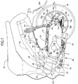
FIG. 2 is a horizontal cross-sectional view of a power unit taken along a line 2-2 inFIG. 1 . -
FIG. 3 is a view along an arrow 3 inFIG. 1 and an enlarged view schematically illustrating an arrangement of a speed detecting sensor. -
FIG. 4 is an enlarged perspective view schematically illustrating an outer surface of a transmission case on which the speed detecting sensor is disposed. -
FIG. 5 is an enlarged plan view schematically illustrating the outer surface of the transmission case on which the speed detecting sensor is disposed. -
FIG. 6 corresponds toFIG. 4 , and is an enlarged perspective view schematically illustrating a sensor cover. -
FIG. 7 is an enlarged side view schematically illustrating a relationship between a U-shaped lock and spokes when the U-shaped lock is mounted. - The following describes one embodiment of the present invention with reference to the attached drawings. It should be noted that the following description defines respective directions of front and rear, up and down, and right and left as directions viewed from an occupant riding on a two-wheeled motor vehicle.
-
FIG. 1 schematically illustrates a scooter type two-wheeled motor vehicle according to one embodiment of a saddle riding vehicle. A two-wheeled motor vehicle 11 includes abody frame 12 and avehicle body cover 13 mounted on thebody frame 12. Thebody frame 12 includes ahead tube 14, adown tube 15, and a pair of right andleft side frames 16. Thedown tube 15 extends downward from thehead tube 14. Theside frames 16 extend rearward from a lower end of thedown tube 15. Thehead tube 14 steerably supports afront fork 17 that supports a front wheel WF rotatably about an axle shaft, and a rod-shaped steering handlebar 18. - The
side frame 16 has adown frame portion 16a, alower frame portion 16b, and aseat rail portion 16c. Thedown frame portion 16a extends downward from a lower end of thedown tube 15. Thelower frame portion 16b extends in parallel with a ground from a rear end of thedown frame portion 16a. Theseat rail portion 16c extends upward to a rear from a rear end of thelower frame portion 16b to be disposed above a rear wheel WR. Above theseat rail portion 16c, anoccupant seat 19 is mounted on thevehicle body cover 13. - The
vehicle body cover 13 includes afront cover 21, aleg shield 22, and astep floor 23. Thefront cover 21 covers thehead tube 14 from the front. Theleg shield 22 is continuous with thefront cover 21. Thestep floor 23 is continuous with a lower end of theleg shield 22 to be disposed above thelower frame portion 16b between theoccupant seat 19 and the front wheel WF. An occupant seating on theoccupant seat 19 can put his/her feet on thestep floor 23. Thelower frame portion 16b supports afuel tank 24 storing a fuel under thestep floor 23. - A unit swing-
type power unit 25 is disposed in a space underneath theseat rail portion 16c. Thepower unit 25 is coupled to abracket 26 swingably in a vertical direction via alink 27. Thebracket 26 is combined to the rear end of thelower frame portion 16b. Thepower unit 25 has a rear end that rotatably supports the rear wheel WR about an axis Hx of a horizontal axis. Thepower unit 25 includes aninternal combustion engine 28 and atransmission device 29. Theinternal combustion engine 28 generates a power based on a fuel supplied from thefuel tank 24. Thetransmission device 29 is coupled to theinternal combustion engine 28 and transmits the power of theinternal combustion engine 28 to the rear wheel WR at a gear ratio that linearly changes. Thetransmission case 32 of thetransmission device 29 is combined to thecrankcase 31 of theinternal combustion engine 28. - A
rear cushion unit 33 is disposed between theseat rail portion 16c and thepower unit 25 at a position apart from thelink 27 and thebracket 26. Thepower unit 25 functions as a suspension device that swingably couples the rear wheel WR to thebody frame 12. - The rear wheel WR includes a
hub 35, arim 37, and a plurality ofspokes hub 35 is combined to thedrive shaft 34 and expands rearward with respect to thetransmission case 32. Therim 37 is disposed coaxially with thehub 35 and supports atire 36 made of rubber. The plurality ofspokes rim 37 to thehub 35. Thespokes front spoke 38a and arear spoke 38b. The front spoke 38a inclines in a direction of forward movement at a prescribed angle α with respect to a diameter line RL about thedrive shaft 34. The rear spoke 38b inclines in a retreat direction at a prescribed angle β with respect to the diameter line RL about thedrive shaft 34. Thehub 35,rim 37, andspokes - The
internal combustion engine 28 includes acrankcase 31, acylinder block 41, acylinder head 42, and ahead cover 43. Thecrankcase 31 supports a crankshaft (described below) rotatably about a rotation axis Rx extending in parallel with the axis Hx of the rear wheel WR. Thecylinder block 41 is combined to thecrankcase 31. Thecylinder head 42 is combined to thecylinder block 41. Thehead cover 43 is combined to thecylinder head 42. Anintake device 44 and anexhaust device 45 are coupled to thecylinder head 42. Theintake device 44 includes anair cleaner 46 and a throttle body 47. Theair cleaner 46 is supported by thetransmission case 32 and suctions and purifies an external air. The throttle body 47 couples theair cleaner 46 to thecylinder head 42. Thecylinder head 42 has an upper wall on which afuel injection device 48 is mounted. Theexhaust device 45 includes anexhaust pipe 49 and an exhaust muffler (not illustrated). Theexhaust pipe 49 extends rearward through underneath theinternal combustion engine 28 from a lower wall of thecylinder head 42. The exhaust muffler is coupled to a downstream end of theexhaust pipe 49 to be coupled to thecrankcase 31. - As illustrated in
FIG. 2 , thecrankcase 31 is divided into a first casehalf body 31a and a second casehalf body 31b. The first casehalf body 31a and the second casehalf body 31b collaborate to partition acrank chamber 51. Thecrank chamber 51 houses a crank of acrankshaft 52. A bearing 53a that rotatably supports thecrankshaft 52 is assembled to the first casehalf body 31a. A bearing 53b that rotatably supports thecrankshaft 52 is assembled to the second casehalf body 31b. - In the
cylinder block 41, a cylinder bore 54 is partitioned. In the cylinder bore 54, apiston 55 is engaged slidably along a cylinder axis C. Thepiston 55 is coupled to the crank of thecrankshaft 52 with a connectingrod 56. A linear reciprocation motion of thepiston 55 is transformed into a rotational motion of thecrankshaft 52. The cylinder axis C inclines slightly upward to a front from the horizon. Acombustion chamber 57 is partitioned between thepiston 55 and thecylinder head 42. An air-fuel mixture is introduced into thecombustion chamber 57 via theintake device 44. An exhaust gas inside thecombustion chamber 57 is discharged via theexhaust device 45. - The
crankshaft 52 has one end to which an AC generator (ACG) 58 is coupled. TheAC generator 58 includes a pipe shapedrotor 58a and astator 58b. Therotor 58a is secured to the one end of thecrankshaft 52 projecting from an outer surface of the first casehalf body 31a. Thestator 58b is disposed around thecrankshaft 52 surrounded by therotor 58a. Thestator 58b is configured of a plurality of coils individually wound around a stator core. Thestator 58b is secured to asupport plate 59 fastened to the first casehalf body 31a. TheAC generator 58 generates electricity in response to relative rotation of therotor 58a and thestator 58b. - The
transmission device 29 includes a belt type continuously variable transmission (hereinafter referred to as "transmission") 65 and adeceleration gear mechanism 67. Thetransmission 65 includes adrive pulley 61 and aV belt 64 to steplessly shift a rotative power transmitted from thecrankshaft 52. Thedrive pulley 61 is housed within thetransmission case 32 and mounted to thecrankshaft 52 projecting from an outer surface of the second casehalf body 31b. TheV belt 64 is wound around a drivenpulley 63 mounted to a drivenshaft 62. Thedeceleration gear mechanism 67 is housed within thetransmission case 32, and decelerates and transmits the rotative power of thetransmission 65 to thedrive shaft 34 of the rear wheel WR. - The
transmission case 32 includes acase entity 68, acase cover 71, and agear cover 73. Thecase entity 68 is continuous with the second casehalf body 31b of thecrankcase 31. The case cover 71 is fastened to thecase entity 68 and partitions atransmission chamber 69 that houses thetransmission 65 between thecase cover 71 and thecase entity 68. Thegear cover 73 is fastened to thecase entity 68 and partitions agear chamber 72 between thegear cover 73 and thecase entity 68. Thegear chamber 72 houses thedeceleration gear mechanism 67. - The
drive pulley 61 includes apulley half body 74 and apulley half body 75. Thepulley half body 74 is secured coaxially to thecrankshaft 52 and has a conical-shaped inward surface. Thepulley half body 75 is supported coaxially to thecrankshaft 52 movably in an axial direction of thecrankshaft 52 and has a conical-shaped inward surface that is caused to face the inward surface of thepulley half body 74. TheV belt 64 is wound around between the inward surface of thepulley half body 74 and the inward surface of thepulley half body 75. Thepulley half body 75 is disposed between the second casehalf body 31b of thecrankcase 31 and thepulley half body 74. - A
cam plate 77 is secured to thepulley half body 75. Thecam plate 77 is caused to face aweight holding member 76 secured to thecrankshaft 52 in a non-displaceable manner in the axial direction. Acentrifugal weight 78 is interposed between thecam plate 77 and theweight holding member 76. Thecam plate 77 recedes from thepulley half body 74 as receding from the rotation axis Rx of thecrankshaft 52 in a centrifugal direction. The centrifugal force is generated in thecentrifugal weight 78 in association with a rotation of thecrankshaft 52. As thecentrifugal weight 78 displaces in the centrifugal direction while thecentrifugal weight 78 rolling contacts thecam plate 77, thepulley half body 75 is driven toward thepulley half body 74. Thus, thepulley half body 75 moves toward thepulley half body 74 in the axial direction in response to the rotation of thecrankshaft 52, and thus, a winding radius of theV belt 64 changes. - The driven
pulley 63 includes aninner pipe 79, apulley half body 81, an outer pipe 82, and apulley half body 83. Theinner pipe 79 has a cylindrical shape coaxial with the drivenshaft 62 to be coaxially mounted on the drivenshaft 62. Thepulley half body 81 is secured to theinner pipe 79 so as to be coaxial with theinner pipe 79. The outer pipe 82 has a cylindrical shape coaxial with the drivenshaft 62 to be coaxially mounted on theinner pipe 79. Thepulley half body 83 is secured to the outer pipe 82 so as to be coaxial with the outer pipe 82, and has an inward surface that faces an inward surface of thepulley half body 81. TheV belt 64 is wound around between the inward surface of thepulley half body 81 and the inward surface of thepulley half body 83. Theinner pipe 79 is relatively rotatably supported by the drivenshaft 62. The outer pipe 82 is supported relatively rotatably and relatively displaceably in the axial direction by theinner pipe 79. In response to the relative displacement in the axial direction of the outer pipe 82 and theinner pipe 79, thepulley half body 83 approaches thepulley half body 81 and recedes from thepulley half body 81. - On the driven
shaft 62, a centrifugal clutch 84 is mounted. The centrifugal clutch 84 includes aclutch plate 84a and anouter plate 84b. Theclutch plate 84a is secured to theinner pipe 79. Theouter plate 84b is secured to the drivenshaft 62 and caused to face theclutch plate 84a. Between theclutch plate 84a and thepulley half body 83, acoiled spring 85 is disposed. Thecoiled spring 85 provides an elastic force to press thepulley half body 83 toward thepulley half body 81. When the winding radius of theV belt 64 increases on thedrive pulley 61, thepulley half body 83 recedes from thepulley half body 81 against the elastic force of the coiledspring 85, and the winding radius of theV belt 64 decreases on the drivenpulley 63. When theclutch plate 84a rotates, theouter plate 84b is combined to theclutch plate 84a by an action of the centrifugal force. Thus, a rotation of the drivenpulley 63 is transmitted to the drivenshaft 62. As soon as the engine speed exceeds a set rotation speed, the centrifugal clutch 84 establishes a power transmission state. - The
deceleration gear mechanism 67 includes adrive gear 86, afinal gear 87, andtransmission gears drive gear 86 is secured to the drivenshaft 62 protruding to thegear chamber 72. Thefinal gear 87 is secured to thedrive shaft 34 of the rear wheel WR to rotate integrally with thedrive shaft 34. The transmission gears 88a, 88b are disposed between thedrive gear 86 and thefinal gear 87. The transmission gears 88a, 88b are secured to a sharedintermediate shaft 89. Thedrive gear 86 engages with thetransmission gear 88a, and thefinal gear 87 engages with thetransmission gear 88b. Thus, the rotation of the drivenshaft 62 is decelerated and transmitted to thedrive shaft 34 of the rear wheel WR. - As illustrated in
FIG. 3 , on thetransmission case 32, aspeed detecting sensor 91 is mounted. Thespeed detecting sensor 91 faces thefinal gear 87 with adetection tip end 91a entering thegear chamber 72 to detect a rotation speed of thedrive shaft 34. Thespeed detecting sensor 91 has acoupling end 91b coupled to aharness 92 outside thetransmission case 32. Thecoupling end 91b projects outside thetransmission case 32 by standing upright from an outer surface of thetransmission case 32. For thespeed detecting sensor 91, it is used one that uses a magnetoresistive element that transforms a magnitude of a magnetic force into an electrical signal according, for example, to presence/absence of teeth of a magnetic material. A detection signal of thespeed detecting sensor 91 is supplied to, for example, an electronic control unit (ECU), which is not illustrated, through theharness 92. - As illustrated in
FIG. 4 , theharness 92 has a firstlinear region 92a, a foldedback region 92b, a secondlinear region 92c, and anon-restrained region 92d. The firstlinear region 92a extends upward from an upper end of thecoupling end 91b to recede from the outer surface of thetransmission case 32. The folded backregion 92b is continuous with the firstlinear region 92a and curves so as to be folded back downward toward the outer surface of thetransmission case 32. The secondlinear region 92c is continuous with the folded backregion 92b and approach the outer surface of thetransmission case 32 along a side surface of thecoupling end 91b. Thenon-restrained region 92d is continuous with the secondlinear region 92c and extends forward along the outer surface of thetransmission case 32. The secondlinear region 92c is fastened to the side surface of thecoupling end 91b with aband 93 made of resin. Thus, a configuration of theharness 92 is restrained by theband 93. - The gear cover 73 of the
transmission case 32 has afastening hole 95 formed at a position displaced from thecoupling end 91b in the axial direction of thedrive shaft 34. Thefastening hole 95 receives afastening bolt 94 of thespeed detecting sensor 91. A mountingpiece 96 that is stacked over an outer surface of thegear cover 73 is secured to thespeed detecting sensor 91. The mountingpiece 96 has a throughhole 97 formed to receive thefastening bolt 94 coaxially to thefastening hole 95. Thefastening bolt 94 exits the throughhole 97 to be screwed into thefastening hole 95. Thespeed detecting sensor 91 is secured to thegear cover 73 of thetransmission case 32 with thefastening bolt 94. - The
case entity 68 of thetransmission case 32 has aprotection wall 98 integrally formed at a position displaced from thecoupling end 91b of thespeed detecting sensor 91 in the axial direction of thedrive shaft 34. Theprotection wall 98 projects from the outer surface of thetransmission case 32. Thefastening hole 95,speed detecting sensor 91, andprotection wall 98 are collocated in this order from a side (inner side of a vehicle) of thehub 35 of the rear wheel WR in the axial direction of thedrive shaft 34. In thecase entity 68 of thetransmission case 32, abracket 99 is integrally formed. Thebracket 99 supports a lower end of therear cushion unit 33 rotatably about a rotation axis parallel to an axial center of thedrive shaft 34. Theprotection wall 98 is disposed at a rear of thebracket 99. As illustrated inFIG. 5 , theprotection wall 98 includes a columnar shapedbase 98a, awall body 98b, and a reinforcingwall 98c. Thebase 98a is continuous with thecase entity 68 and has an axis Cx parallel to an axial center of thedrive shaft 34. Thewall body 98b is integrated with a rear end of thebase 98a while being continuous with thecase entity 68 and specifies anupright surface 101 in a planar surface parallel to the axial center of thedrive shaft 34. The reinforcingwall 98c extends along a virtual plane perpendicular to the axial center of thedrive shaft 34 while being continuous with an inward surface of thebase 98a and is integrated with thewall body 98b on aridgeline 102 standing upright from the outer surface of thetransmission case 32. Theridgeline 102 of thewall body 98b and the reinforcingwall 98c has a height as high as thecoupling end 91b of thespeed detecting sensor 91. Theprotection wall 98 has a rear end (virtual plane PP including the upright surface 101) that is positioned at a rear with respect to a rear end of thespeed detecting sensor 91 about the axis of thedrive shaft 34. Ascrew hole 103 coaxial with the axis Cx is drilled on thebase 98a of theprotection wall 98. In thescrew hole 103, a thread groove for a female screw is threaded. - As illustrated in
FIG. 6 , asensor cover 105 that houses thecoupling end 91b of thespeed detecting sensor 91 and theprotection wall 98 is mounted on the outer surface of thetransmission case 32. Thesensor cover 105 is secured to thetransmission case 32 with ascrew member 106. Thescrew member 106 is screwed into thescrew hole 103 formed in thebase 98a of theprotection wall 98 as described above. Thesensor cover 105 is molded from, for example, a resin material. - A
breather tube 107 is mounted on thegear cover 73 of thetransmission case 32. Thebreather tube 107 is drawn out from the outer surface of thetransmission case 32 in front of thespeed detecting sensor 91 and extends forward. Thebreather tube 107 is disposed at a position displaced from theharness 92 in the axial direction of thedrive shaft 34. Thebreather tube 107 extends forward in parallel with thenon-restrained region 92d of theharness 92. - Next, a description will be given of an operation of the
power unit 25 according to the embodiment. Repeated strokes of air intake, compression, combustion, and exhaustion in thecombustion chamber 57 cause thepiston 55 to make the linear reciprocation motion within the cylinder bore 54, thus causing the rotation of thecrankshaft 52. The rotation of thedrive pulley 61 is transmitted to the drivenpulley 63 by an action of theV belt 64. As soon as the engine speed exceeds the set rotation speed, the centrifugal clutch 84 establishes the power transmission state, and thus, the rotation of the drivenpulley 63 is transmitted to the drivenshaft 62. The rotation of the drivenshaft 62 is transmitted from thedrive gear 86 to thefinal gear 87 via the transmission gears 88a, 88b. Thus, thedrive shaft 34 of the rear wheel WR rotates. When the rotation speed of thedrive pulley 61 increases, thecentrifugal weight 78 displaces radially outward and the winding radius of theV belt 64 increases. The winding radius of the drivenpulley 63 decreases according to the winding radius of thedrive pulley 61. Thus, thetransmission 65 steplessly shifts a gear ratio. - The
speed detecting sensor 91 detects a rotation speed of thefinal gear 87 according to the presence/absence of the teeth of thefinal gear 87. Since the rear wheel WR and thefinal gear 87 are secured to thedrive shaft 34 in a relatively unrotatable manner, the rotation speed of thefinal gear 87 reflects a travelling speed of the two-wheeledmotor vehicle 11. Thus, thespeed detecting sensor 91 detects the travelling speed of the two-wheeledmotor vehicle 11. The travelling speed is, for example, displayed on a speedometer. - As illustrated in
FIG. 7 , when ashaft body 108 of a U-shaped lock is mounted on the rear wheel WR, theshaft body 108 of the U-shaped lock collides with thewall body 98b of theprotection wall 98 at a position displaced from thecoupling end 91b of thespeed detecting sensor 91 when the two-wheeledmotor vehicle 11 moves forward and the rear wheel WR rotates, and thus, a collision between the U-shaped lock and thespeed detecting sensor 91 is avoided. When theshaft body 108 of the U-shaped lock is installed in a front side of the front spoke 38a in the direction of forward movement about thedrive shaft 34, theshaft body 108 of the U-shaped lock is interposed between thefront spoke 38a and theupright surface 101 of thewall body 98b because an outer periphery of thehub 35 and the front spoke 38a intersect at an acute angle. Therefore, a movement of the U-shaped lock is restrained. Thespeed detecting sensor 91 is reliably protected. Moreover, theprotection wall 98 only receives the U-shaped lock about the axis of thedrive shaft 34, and thus, theprotection wall 98 is downsized. When theshaft body 108 of the U-shaped lock is installed in a front side of the rear spoke 38b in the direction of forward movement about thedrive shaft 34, while theshaft body 108 of the U-shaped lock is restrained in the direction of forward movement about thedrive shaft 34 by an action of theprotection wall 98, an action of a cam of therear spoke 38b ensures a radially outward displacement because the outer periphery of thehub 35 and the rear spoke 38b intersect at an obtuse angle. Thus, the rear spoke 38b can go over a top end of thewall body 98b. The U-shaped lock is caused to escape radially outward, thereby reducing an impact of the U-shaped lock. Thespeed detecting sensor 91 is reliably protected. - In particular, since the
wall body 98b of theprotection wall 98 is positioned at a rear with respect to a rear end of thespeed detecting sensor 91 about the axis of thedrive shaft 34, even though the rear wheel WR rotates when the U-shaped lock is mounted, the U-shaped lock collides with theprotection wall 98 prior to thespeed detecting sensor 91, thereby reliably protecting thespeed detecting sensor 91. - In this embodiment, the
sensor cover 105, which houses thecoupling end 91b of thespeed detecting sensor 91 and theprotection wall 98, is mounted on the outer surface of thetransmission case 32. Since thesensor cover 105 covers thecoupling end 91b of thespeed detecting sensor 91, thesensor cover 105 protects thespeed detecting sensor 91 from, for example, gravels splashed. In addition, since thesensor cover 105 covers over thespeed detecting sensor 91 and theprotection wall 98, designability of the two-wheeledmotor vehicle 11 in which thepower unit 25 is incorporated is properly maintained. - The first
linear region 92a of theharness 92 extends upward from the upper end of thecoupling end 91b of thespeed detecting sensor 91 standing upright from the outer surface of thetransmission case 32. Theharness 92 thus extending upward from thecoupling end 91b of thespeed detecting sensor 91 avoids the interference between theprotection wall 98 and theharness 92. Theprotection wall 98 projects from the outer surface of thetransmission case 32 at the position displaced from thecoupling end 91b in the axial direction of thedrive shaft 34. Theprotection wall 98 can approach close to thecoupling end 91b of thespeed detecting sensor 91 as close as possible. An arrangement space is reduced. - The
transmission case 32 has thefastening hole 95, which receives thefastening bolt 94 of thespeed detecting sensor 91, formed at the position displaced from thecoupling end 91b of thespeed detecting sensor 91 in the axial direction of thedrive shaft 34. Thespeed detecting sensor 91 is secured to thegear cover 73 of thetransmission case 32 with thefastening bolt 94 screwed into thefastening hole 95. The action of theprotection wall 98 ensures protecting thefastening bolt 94 together with thespeed detecting sensor 91 from the U-shaped lock. - On the
transmission case 32, thebreather tube 107 is mounted. Thebreather tube 107 is drawn out from the outer surface of thetransmission case 32 in front of thespeed detecting sensor 91 and extends forward. Thus, thebreather tube 107 is disposed without interfering thespeed detecting sensor 91 and theprotection wall 98. Moreover, since thebreather tube 107 is disposed at the position displaced from theharness 92 in the axial direction of thedrive shaft 34, thebreather tube 107 is disposed without interfering with theharness 92 of thespeed detecting sensor 91. -
- 25... Power unit
- 32... Transmission case
- 34... Drive shaft (of rear wheel)
- 87... Gear (final gear)
- 91... Speed detecting sensor
- 91a... Detection tip end
- 91b... Coupling end
- 92... Harness
- 94... Fastening bolt
- 95... Fastening hole
- 98... Protection wall
- 105... Sensor cover
- 107... Breather tube
- WR... Rear wheel
Claims (7)
- A power unit comprising:a gear (87) mounted on a drive shaft (34) of a rear wheel (WR) in a transmission case (32) so as to rotate integrally with the drive shaft (34); anda speed detecting sensor (91) having a detection tip end (91a) that faces the gear (87), having a coupling end (91b) coupled to a harness (92) outside the transmission case (32), and detecting a rotation speed of the drive shaft (34),characterized in thata protection wall (98) projects from an outer surface of the transmission case (32) at a position displaced from the coupling end (91b) in an axial direction of the drive shaft (34).
- The power unit according to claim 1,
wherein the protection wall (98) is positioned rearward of a rear end of the speed detecting sensor (91) about an axis of the drive shaft (34). - The power unit according to claim 1 or 2, further comprising
a sensor cover (105) mounted on the outer surface of the transmission case (32), and housing the coupling end (91b) and the protection wall (98). - The power unit according to any one of claims 1 to 3,
wherein the harness (92) extends upward from an upper end of the coupling end (91b). - The power unit according to any one of claims 1 to 4,
wherein the transmission case (32) has a fastening hole (95) formed at a position displaced from the coupling end (91b) in the axial direction of the drive shaft (34), the fastening hole (95) receiving a fastening bolt (94) of the speed detecting sensor (91). - The power unit according to any one of claims 1 to 5, further comprising
a breather tube (107) drawn out from the outer surface of transmission case (32) in front of the speed detecting sensor (91) so as to extend forward. - The power unit according to claim 6,
wherein the breather tube (107) is disposed at a position displaced from the harness (92) in the axial direction of the drive shaft (34).
Applications Claiming Priority (1)
| Application Number | Priority Date | Filing Date | Title |
|---|---|---|---|
| JP2018060897A JP6799556B2 (en) | 2018-03-27 | 2018-03-27 | Power unit |
Publications (2)
| Publication Number | Publication Date |
|---|---|
| EP3546333A1 true EP3546333A1 (en) | 2019-10-02 |
| EP3546333B1 EP3546333B1 (en) | 2021-11-17 |
Family
ID=65894852
Family Applications (1)
| Application Number | Title | Priority Date | Filing Date |
|---|---|---|---|
| EP19163339.5A Active EP3546333B1 (en) | 2018-03-27 | 2019-03-18 | Power unit |
Country Status (3)
| Country | Link |
|---|---|
| EP (1) | EP3546333B1 (en) |
| JP (1) | JP6799556B2 (en) |
| CN (1) | CN110308299B (en) |
Citations (4)
| Publication number | Priority date | Publication date | Assignee | Title |
|---|---|---|---|---|
| JP2005178633A (en) * | 2003-12-19 | 2005-07-07 | Suzuki Motor Corp | Wheel speed detection device for motorcycles |
| EP1880934A2 (en) * | 2006-07-19 | 2008-01-23 | Honda Motor Co., Ltd | Motorcycle |
| EP2065620A1 (en) * | 2007-11-30 | 2009-06-03 | Honda Motor Co., Ltd | Motorcycle |
| JP2010076604A (en) | 2008-09-26 | 2010-04-08 | Honda Motor Co Ltd | Driving wheel speed sensor protective structure for power unit |
Family Cites Families (24)
| Publication number | Priority date | Publication date | Assignee | Title |
|---|---|---|---|---|
| JPS56160249A (en) * | 1980-06-26 | 1981-12-09 | Honda Motor Co Ltd | Antiskid brake apparatus of autobicycle |
| JPS61181757A (en) * | 1985-02-07 | 1986-08-14 | Honda Motor Co Ltd | Wheel angular acceleration sensor drive device |
| JP3182435B2 (en) * | 1991-09-25 | 2001-07-03 | 本田技研工業株式会社 | Speed detector for motorcycles |
| JP4104198B2 (en) * | 1998-01-30 | 2008-06-18 | 本田技研工業株式会社 | Motorcycle headlight and speedometer mounting device |
| JP3456903B2 (en) * | 1998-09-14 | 2003-10-14 | 本田技研工業株式会社 | Internal combustion engine for motorcycles |
| JP4057246B2 (en) * | 2001-01-09 | 2008-03-05 | 本田技研工業株式会社 | Vehicle wheel speed detection sensor protection structure |
| JP4083405B2 (en) * | 2001-09-25 | 2008-04-30 | 本田技研工業株式会社 | Vehicle body structure |
| JP2005300481A (en) * | 2004-04-15 | 2005-10-27 | Honda Motor Co Ltd | Motorcycle with vehicle speed sensor |
| CN100361842C (en) * | 2004-07-20 | 2008-01-16 | 通用汽车公司 | Connector for electronic communication line, transmission box assembly including same and connection method thereof |
| JP4739138B2 (en) * | 2006-07-21 | 2011-08-03 | 本田技研工業株式会社 | Sensor cover structure |
| JP4856487B2 (en) * | 2006-07-19 | 2012-01-18 | 本田技研工業株式会社 | Scooter type motorcycle |
| DE602008000573D1 (en) * | 2007-07-26 | 2010-03-11 | Honda Motor Co Ltd | engine |
| JP2009030716A (en) * | 2007-07-26 | 2009-02-12 | Honda Motor Co Ltd | Power unit wiring structure |
| JP2009029253A (en) * | 2007-07-26 | 2009-02-12 | Honda Motor Co Ltd | Breather structure of power unit deceleration chamber |
| JP2009067336A (en) * | 2007-09-18 | 2009-04-02 | Yamaha Motor Co Ltd | Motorcycle |
| JP5417080B2 (en) * | 2009-08-03 | 2014-02-12 | 本田技研工業株式会社 | Auxiliary arrangement structure of power unit for vehicle |
| JP5546302B2 (en) * | 2010-03-19 | 2014-07-09 | 本田技研工業株式会社 | Vehicle speed sensor mounting structure |
| TWI492876B (en) * | 2010-11-18 | 2015-07-21 | Honda Motor Co Ltd | Drive device of electrical vehicle |
| JP2014163469A (en) * | 2013-02-26 | 2014-09-08 | Honda Motor Co Ltd | Rotational speed sensor for transmission |
| JP6101578B2 (en) * | 2013-06-25 | 2017-03-22 | 本田技研工業株式会社 | Vehicle speed detection structure |
| KR101405149B1 (en) * | 2013-09-30 | 2014-06-10 | 박선화 | Backward gear for motorcycle |
| CN204044173U (en) * | 2014-09-24 | 2014-12-24 | 株洲惠泽科技有限责任公司 | A kind of base installed for railcar speed pickup |
| CN107249972B (en) * | 2015-03-31 | 2020-08-11 | 本田技研工业株式会社 | Support structure of wheel speed sensor |
| JP6678088B2 (en) * | 2016-09-26 | 2020-04-08 | 本田技研工業株式会社 | Power unit drive wheel speed detection sensor protection structure |
-
2018
- 2018-03-27 JP JP2018060897A patent/JP6799556B2/en not_active Expired - Fee Related
-
2019
- 2019-03-18 EP EP19163339.5A patent/EP3546333B1/en active Active
- 2019-03-26 CN CN201910230884.2A patent/CN110308299B/en active Active
Patent Citations (4)
| Publication number | Priority date | Publication date | Assignee | Title |
|---|---|---|---|---|
| JP2005178633A (en) * | 2003-12-19 | 2005-07-07 | Suzuki Motor Corp | Wheel speed detection device for motorcycles |
| EP1880934A2 (en) * | 2006-07-19 | 2008-01-23 | Honda Motor Co., Ltd | Motorcycle |
| EP2065620A1 (en) * | 2007-11-30 | 2009-06-03 | Honda Motor Co., Ltd | Motorcycle |
| JP2010076604A (en) | 2008-09-26 | 2010-04-08 | Honda Motor Co Ltd | Driving wheel speed sensor protective structure for power unit |
Also Published As
| Publication number | Publication date |
|---|---|
| JP2019171994A (en) | 2019-10-10 |
| JP6799556B2 (en) | 2020-12-16 |
| CN110308299A (en) | 2019-10-08 |
| EP3546333B1 (en) | 2021-11-17 |
| CN110308299B (en) | 2021-10-22 |
Similar Documents
| Publication | Publication Date | Title |
|---|---|---|
| CN100470088C (en) | V-belt continuously variable transmissions and pedal vehicles | |
| US8757314B2 (en) | Chain drive for saddle-ride type vehicle | |
| US20110073391A1 (en) | Hybrid vehicle | |
| CN101186228B (en) | Motorcycle | |
| US7409949B1 (en) | Ignition housing for internal combustion engine | |
| CN101683847A (en) | Drive wheel speed detection sensor protection structure of power unit | |
| EP3552937A1 (en) | Saddle type vehicle | |
| US20200407006A1 (en) | Front fork lower portion structure of saddle riding vehicle | |
| EP2669482B1 (en) | Intake system for internal combustion engine | |
| EP3546333B1 (en) | Power unit | |
| JP7015936B2 (en) | Internal combustion engine | |
| JP5417080B2 (en) | Auxiliary arrangement structure of power unit for vehicle | |
| EP3992441B1 (en) | Internal combustion engine structure | |
| US10975787B2 (en) | Internal combustion engine | |
| JP4280361B2 (en) | Air cleaner intake structure for motorcycles | |
| EP3597964B1 (en) | Belt-type continuously variable transmission | |
| CN112664293B (en) | Internal combustion engines for saddle-riding vehicles | |
| CN110520614B (en) | Internal combustion engine | |
| EP3543503A1 (en) | Swing unit-type power unit | |
| CN110949577B (en) | Power unit for saddle-riding vehicles | |
| US11215480B2 (en) | Rotation speed detecting apparatus of internal combustion engine | |
| EP3882113B1 (en) | Saddled vehicle | |
| JP7216129B2 (en) | straddle-type vehicle | |
| CN110475960A (en) | internal combustion engine | |
| JP2014118914A (en) | Electronic control throttle device |
Legal Events
| Date | Code | Title | Description |
|---|---|---|---|
| PUAI | Public reference made under article 153(3) epc to a published international application that has entered the european phase |
Free format text: ORIGINAL CODE: 0009012 |
|
| STAA | Information on the status of an ep patent application or granted ep patent |
Free format text: STATUS: REQUEST FOR EXAMINATION WAS MADE |
|
| 17P | Request for examination filed |
Effective date: 20190318 |
|
| AK | Designated contracting states |
Kind code of ref document: A1 Designated state(s): AL AT BE BG CH CY CZ DE DK EE ES FI FR GB GR HR HU IE IS IT LI LT LU LV MC MK MT NL NO PL PT RO RS SE SI SK SM TR |
|
| AX | Request for extension of the european patent |
Extension state: BA ME |
|
| STAA | Information on the status of an ep patent application or granted ep patent |
Free format text: STATUS: EXAMINATION IS IN PROGRESS |
|
| 17Q | First examination report despatched |
Effective date: 20200707 |
|
| GRAP | Despatch of communication of intention to grant a patent |
Free format text: ORIGINAL CODE: EPIDOSNIGR1 |
|
| STAA | Information on the status of an ep patent application or granted ep patent |
Free format text: STATUS: GRANT OF PATENT IS INTENDED |
|
| INTG | Intention to grant announced |
Effective date: 20210611 |
|
| GRAS | Grant fee paid |
Free format text: ORIGINAL CODE: EPIDOSNIGR3 |
|
| GRAA | (expected) grant |
Free format text: ORIGINAL CODE: 0009210 |
|
| STAA | Information on the status of an ep patent application or granted ep patent |
Free format text: STATUS: THE PATENT HAS BEEN GRANTED |
|
| AK | Designated contracting states |
Kind code of ref document: B1 Designated state(s): AL AT BE BG CH CY CZ DE DK EE ES FI FR GB GR HR HU IE IS IT LI LT LU LV MC MK MT NL NO PL PT RO RS SE SI SK SM TR |
|
| REG | Reference to a national code |
Ref country code: GB Ref legal event code: FG4D |
|
| REG | Reference to a national code |
Ref country code: DE Ref legal event code: R096 Ref document number: 602019009262 Country of ref document: DE |
|
| REG | Reference to a national code |
Ref country code: IE Ref legal event code: FG4D |
|
| REG | Reference to a national code |
Ref country code: AT Ref legal event code: REF Ref document number: 1447836 Country of ref document: AT Kind code of ref document: T Effective date: 20211215 |
|
| REG | Reference to a national code |
Ref country code: LT Ref legal event code: MG9D |
|
| REG | Reference to a national code |
Ref country code: NL Ref legal event code: MP Effective date: 20211117 |
|
| REG | Reference to a national code |
Ref country code: AT Ref legal event code: MK05 Ref document number: 1447836 Country of ref document: AT Kind code of ref document: T Effective date: 20211117 |
|
| PG25 | Lapsed in a contracting state [announced via postgrant information from national office to epo] |
Ref country code: RS Free format text: LAPSE BECAUSE OF FAILURE TO SUBMIT A TRANSLATION OF THE DESCRIPTION OR TO PAY THE FEE WITHIN THE PRESCRIBED TIME-LIMIT Effective date: 20211117 Ref country code: LT Free format text: LAPSE BECAUSE OF FAILURE TO SUBMIT A TRANSLATION OF THE DESCRIPTION OR TO PAY THE FEE WITHIN THE PRESCRIBED TIME-LIMIT Effective date: 20211117 Ref country code: FI Free format text: LAPSE BECAUSE OF FAILURE TO SUBMIT A TRANSLATION OF THE DESCRIPTION OR TO PAY THE FEE WITHIN THE PRESCRIBED TIME-LIMIT Effective date: 20211117 Ref country code: BG Free format text: LAPSE BECAUSE OF FAILURE TO SUBMIT A TRANSLATION OF THE DESCRIPTION OR TO PAY THE FEE WITHIN THE PRESCRIBED TIME-LIMIT Effective date: 20220217 Ref country code: AT Free format text: LAPSE BECAUSE OF FAILURE TO SUBMIT A TRANSLATION OF THE DESCRIPTION OR TO PAY THE FEE WITHIN THE PRESCRIBED TIME-LIMIT Effective date: 20211117 |
|
| PG25 | Lapsed in a contracting state [announced via postgrant information from national office to epo] |
Ref country code: IS Free format text: LAPSE BECAUSE OF FAILURE TO SUBMIT A TRANSLATION OF THE DESCRIPTION OR TO PAY THE FEE WITHIN THE PRESCRIBED TIME-LIMIT Effective date: 20220317 Ref country code: SE Free format text: LAPSE BECAUSE OF FAILURE TO SUBMIT A TRANSLATION OF THE DESCRIPTION OR TO PAY THE FEE WITHIN THE PRESCRIBED TIME-LIMIT Effective date: 20211117 Ref country code: PT Free format text: LAPSE BECAUSE OF FAILURE TO SUBMIT A TRANSLATION OF THE DESCRIPTION OR TO PAY THE FEE WITHIN THE PRESCRIBED TIME-LIMIT Effective date: 20220317 Ref country code: PL Free format text: LAPSE BECAUSE OF FAILURE TO SUBMIT A TRANSLATION OF THE DESCRIPTION OR TO PAY THE FEE WITHIN THE PRESCRIBED TIME-LIMIT Effective date: 20211117 Ref country code: NO Free format text: LAPSE BECAUSE OF FAILURE TO SUBMIT A TRANSLATION OF THE DESCRIPTION OR TO PAY THE FEE WITHIN THE PRESCRIBED TIME-LIMIT Effective date: 20220217 Ref country code: NL Free format text: LAPSE BECAUSE OF FAILURE TO SUBMIT A TRANSLATION OF THE DESCRIPTION OR TO PAY THE FEE WITHIN THE PRESCRIBED TIME-LIMIT Effective date: 20211117 Ref country code: LV Free format text: LAPSE BECAUSE OF FAILURE TO SUBMIT A TRANSLATION OF THE DESCRIPTION OR TO PAY THE FEE WITHIN THE PRESCRIBED TIME-LIMIT Effective date: 20211117 Ref country code: HR Free format text: LAPSE BECAUSE OF FAILURE TO SUBMIT A TRANSLATION OF THE DESCRIPTION OR TO PAY THE FEE WITHIN THE PRESCRIBED TIME-LIMIT Effective date: 20211117 Ref country code: GR Free format text: LAPSE BECAUSE OF FAILURE TO SUBMIT A TRANSLATION OF THE DESCRIPTION OR TO PAY THE FEE WITHIN THE PRESCRIBED TIME-LIMIT Effective date: 20220218 Ref country code: ES Free format text: LAPSE BECAUSE OF FAILURE TO SUBMIT A TRANSLATION OF THE DESCRIPTION OR TO PAY THE FEE WITHIN THE PRESCRIBED TIME-LIMIT Effective date: 20211117 |
|
| PG25 | Lapsed in a contracting state [announced via postgrant information from national office to epo] |
Ref country code: SM Free format text: LAPSE BECAUSE OF FAILURE TO SUBMIT A TRANSLATION OF THE DESCRIPTION OR TO PAY THE FEE WITHIN THE PRESCRIBED TIME-LIMIT Effective date: 20211117 Ref country code: SK Free format text: LAPSE BECAUSE OF FAILURE TO SUBMIT A TRANSLATION OF THE DESCRIPTION OR TO PAY THE FEE WITHIN THE PRESCRIBED TIME-LIMIT Effective date: 20211117 Ref country code: RO Free format text: LAPSE BECAUSE OF FAILURE TO SUBMIT A TRANSLATION OF THE DESCRIPTION OR TO PAY THE FEE WITHIN THE PRESCRIBED TIME-LIMIT Effective date: 20211117 Ref country code: EE Free format text: LAPSE BECAUSE OF FAILURE TO SUBMIT A TRANSLATION OF THE DESCRIPTION OR TO PAY THE FEE WITHIN THE PRESCRIBED TIME-LIMIT Effective date: 20211117 Ref country code: DK Free format text: LAPSE BECAUSE OF FAILURE TO SUBMIT A TRANSLATION OF THE DESCRIPTION OR TO PAY THE FEE WITHIN THE PRESCRIBED TIME-LIMIT Effective date: 20211117 Ref country code: CZ Free format text: LAPSE BECAUSE OF FAILURE TO SUBMIT A TRANSLATION OF THE DESCRIPTION OR TO PAY THE FEE WITHIN THE PRESCRIBED TIME-LIMIT Effective date: 20211117 |
|
| REG | Reference to a national code |
Ref country code: DE Ref legal event code: R097 Ref document number: 602019009262 Country of ref document: DE |
|
| PLBE | No opposition filed within time limit |
Free format text: ORIGINAL CODE: 0009261 |
|
| STAA | Information on the status of an ep patent application or granted ep patent |
Free format text: STATUS: NO OPPOSITION FILED WITHIN TIME LIMIT |
|
| REG | Reference to a national code |
Ref country code: DE Ref legal event code: R119 Ref document number: 602019009262 Country of ref document: DE |
|
| 26N | No opposition filed |
Effective date: 20220818 |
|
| PG25 | Lapsed in a contracting state [announced via postgrant information from national office to epo] |
Ref country code: MC Free format text: LAPSE BECAUSE OF FAILURE TO SUBMIT A TRANSLATION OF THE DESCRIPTION OR TO PAY THE FEE WITHIN THE PRESCRIBED TIME-LIMIT Effective date: 20211117 Ref country code: AL Free format text: LAPSE BECAUSE OF FAILURE TO SUBMIT A TRANSLATION OF THE DESCRIPTION OR TO PAY THE FEE WITHIN THE PRESCRIBED TIME-LIMIT Effective date: 20211117 |
|
| REG | Reference to a national code |
Ref country code: CH Ref legal event code: PL |
|
| PG25 | Lapsed in a contracting state [announced via postgrant information from national office to epo] |
Ref country code: SI Free format text: LAPSE BECAUSE OF FAILURE TO SUBMIT A TRANSLATION OF THE DESCRIPTION OR TO PAY THE FEE WITHIN THE PRESCRIBED TIME-LIMIT Effective date: 20211117 |
|
| REG | Reference to a national code |
Ref country code: BE Ref legal event code: MM Effective date: 20220331 |
|
| PG25 | Lapsed in a contracting state [announced via postgrant information from national office to epo] |
Ref country code: LU Free format text: LAPSE BECAUSE OF NON-PAYMENT OF DUE FEES Effective date: 20220318 Ref country code: LI Free format text: LAPSE BECAUSE OF NON-PAYMENT OF DUE FEES Effective date: 20220331 Ref country code: IE Free format text: LAPSE BECAUSE OF NON-PAYMENT OF DUE FEES Effective date: 20220318 Ref country code: FR Free format text: LAPSE BECAUSE OF NON-PAYMENT OF DUE FEES Effective date: 20220331 Ref country code: DE Free format text: LAPSE BECAUSE OF NON-PAYMENT OF DUE FEES Effective date: 20221001 Ref country code: CH Free format text: LAPSE BECAUSE OF NON-PAYMENT OF DUE FEES Effective date: 20220331 |
|
| PG25 | Lapsed in a contracting state [announced via postgrant information from national office to epo] |
Ref country code: BE Free format text: LAPSE BECAUSE OF NON-PAYMENT OF DUE FEES Effective date: 20220331 |
|
| GBPC | Gb: european patent ceased through non-payment of renewal fee |
Effective date: 20230318 |
|
| PG25 | Lapsed in a contracting state [announced via postgrant information from national office to epo] |
Ref country code: GB Free format text: LAPSE BECAUSE OF NON-PAYMENT OF DUE FEES Effective date: 20230318 |
|
| PG25 | Lapsed in a contracting state [announced via postgrant information from national office to epo] |
Ref country code: GB Free format text: LAPSE BECAUSE OF NON-PAYMENT OF DUE FEES Effective date: 20230318 |
|
| PG25 | Lapsed in a contracting state [announced via postgrant information from national office to epo] |
Ref country code: MK Free format text: LAPSE BECAUSE OF FAILURE TO SUBMIT A TRANSLATION OF THE DESCRIPTION OR TO PAY THE FEE WITHIN THE PRESCRIBED TIME-LIMIT Effective date: 20211117 Ref country code: CY Free format text: LAPSE BECAUSE OF FAILURE TO SUBMIT A TRANSLATION OF THE DESCRIPTION OR TO PAY THE FEE WITHIN THE PRESCRIBED TIME-LIMIT Effective date: 20211117 |
|
| PG25 | Lapsed in a contracting state [announced via postgrant information from national office to epo] |
Ref country code: HU Free format text: LAPSE BECAUSE OF FAILURE TO SUBMIT A TRANSLATION OF THE DESCRIPTION OR TO PAY THE FEE WITHIN THE PRESCRIBED TIME-LIMIT; INVALID AB INITIO Effective date: 20190318 |
|
| PG25 | Lapsed in a contracting state [announced via postgrant information from national office to epo] |
Ref country code: MT Free format text: LAPSE BECAUSE OF FAILURE TO SUBMIT A TRANSLATION OF THE DESCRIPTION OR TO PAY THE FEE WITHIN THE PRESCRIBED TIME-LIMIT Effective date: 20211117 |
|
| PG25 | Lapsed in a contracting state [announced via postgrant information from national office to epo] |
Ref country code: TR Free format text: LAPSE BECAUSE OF FAILURE TO SUBMIT A TRANSLATION OF THE DESCRIPTION OR TO PAY THE FEE WITHIN THE PRESCRIBED TIME-LIMIT Effective date: 20211117 |
|
| PGFP | Annual fee paid to national office [announced via postgrant information from national office to epo] |
Ref country code: IT Payment date: 20260219 Year of fee payment: 8 |