EP3546329A1 - Throttle opening detecting apparatus for saddle riding vehicle - Google Patents
Throttle opening detecting apparatus for saddle riding vehicle Download PDFInfo
- Publication number
- EP3546329A1 EP3546329A1 EP19159825.9A EP19159825A EP3546329A1 EP 3546329 A1 EP3546329 A1 EP 3546329A1 EP 19159825 A EP19159825 A EP 19159825A EP 3546329 A1 EP3546329 A1 EP 3546329A1
- Authority
- EP
- European Patent Office
- Prior art keywords
- throttle opening
- handlebar
- disposed
- switch
- plate
- Prior art date
- Legal status (The legal status is an assumption and is not a legal conclusion. Google has not performed a legal analysis and makes no representation as to the accuracy of the status listed.)
- Granted
Links
Images


Classifications
-
- B—PERFORMING OPERATIONS; TRANSPORTING
- B62—LAND VEHICLES FOR TRAVELLING OTHERWISE THAN ON RAILS
- B62J—CYCLE SADDLES OR SEATS; AUXILIARY DEVICES OR ACCESSORIES SPECIALLY ADAPTED TO CYCLES AND NOT OTHERWISE PROVIDED FOR, e.g. ARTICLE CARRIERS OR CYCLE PROTECTORS
- B62J23/00—Other protectors specially adapted for cycles
-
- B—PERFORMING OPERATIONS; TRANSPORTING
- B62—LAND VEHICLES FOR TRAVELLING OTHERWISE THAN ON RAILS
- B62K—CYCLES; CYCLE FRAMES; CYCLE STEERING DEVICES; RIDER-OPERATED TERMINAL CONTROLS SPECIALLY ADAPTED FOR CYCLES; CYCLE AXLE SUSPENSIONS; CYCLE SIDECARS, FORECARS, OR THE LIKE
- B62K23/00—Rider-operated controls specially adapted for cycles, i.e. means for initiating control operations, e.g. levers, grips
- B62K23/02—Rider-operated controls specially adapted for cycles, i.e. means for initiating control operations, e.g. levers, grips hand actuated
- B62K23/04—Twist grips
-
- F—MECHANICAL ENGINEERING; LIGHTING; HEATING; WEAPONS; BLASTING
- F02—COMBUSTION ENGINES; HOT-GAS OR COMBUSTION-PRODUCT ENGINE PLANTS
- F02D—CONTROLLING COMBUSTION ENGINES
- F02D11/00—Arrangements for, or adaptations to, non-automatic engine control initiation means, e.g. operator initiated
- F02D11/02—Arrangements for, or adaptations to, non-automatic engine control initiation means, e.g. operator initiated characterised by hand, foot, or like operator controlled initiation means
-
- B—PERFORMING OPERATIONS; TRANSPORTING
- B62—LAND VEHICLES FOR TRAVELLING OTHERWISE THAN ON RAILS
- B62K—CYCLES; CYCLE FRAMES; CYCLE STEERING DEVICES; RIDER-OPERATED TERMINAL CONTROLS SPECIALLY ADAPTED FOR CYCLES; CYCLE AXLE SUSPENSIONS; CYCLE SIDECARS, FORECARS, OR THE LIKE
- B62K2202/00—Motorised scooters
-
- F—MECHANICAL ENGINEERING; LIGHTING; HEATING; WEAPONS; BLASTING
- F02—COMBUSTION ENGINES; HOT-GAS OR COMBUSTION-PRODUCT ENGINE PLANTS
- F02D—CONTROLLING COMBUSTION ENGINES
- F02D2200/00—Input parameters for engine control
- F02D2200/02—Input parameters for engine control the parameters being related to the engine
- F02D2200/04—Engine intake system parameters
- F02D2200/0404—Throttle position
Definitions
- the present invention relates to a throttle opening detecting apparatus for a saddle riding vehicle.
- an opening sensor is used for detecting a throttle opening.
- the opening sensor is mounted to a handlebar and detects a displacement by rotation of a rotor fixed to a throttle pipe.
- a switch group is mounted to the handlebar together with the opening sensor.
- Patent Document 1 Japanese Patent Laid-open No. 2017-133449
- a handlebar has an opening sensor configured integrally with a throttle pipe mounted thereto and a switch group mounted thereto. Accordingly, the switch group is disposed with respect to the throttle pipe with the opening sensor interposed therebetween.
- the switch group In order for an operator of the motorcycle to operate the switch group while driving, it is necessary that the switch group be appropriately disposed in a range in which a finger of the operator can reach in a state in which the operator grasps the throttle grip.
- the present invention has been made in view of the foregoing circumstances, and it is an object of the present invention to provide a throttle opening detecting apparatus for a saddle riding vehicle in which a throttle opening sensor and a switch group attached to a handlebar are configured in a compact manner and the opening sensor is hardly affected by an external force such as a magnetic force.
- a throttle opening detecting apparatus for a saddle riding vehicle which includes a handle cover (1), a handle switch group (61, 62, 63), and a handlebar (2), and in which a throttle opening sensor (4) fixed to the handlebar (2) and detecting a displacement of a rotor (43) inside a sensor case (41) is included in the handle cover (1).
- a throttle opening sensor (4) fixed to the handlebar (2) and detecting a displacement of a rotor (43) inside a sensor case (41) is included in the handle cover (1).
- at least one switch of the handle switch group (61, 62, 63) is disposed at a position facing the sensor case (41) in the handle cover (1), and the sensor case (41) has a step portion (41a) formed on a side surface thereof on a side opposite to a throttle pipe (5) rotated integrally with the rotor (43).
- the step portion (41a) may be disposed behind the throttle pipe (5).
- the step portion (41a) may be formed in an arcuate shape.
- a set plate (7) holding the handlebar (2) may be connected to the sensor case (41), the set plate (7) may include two divided parts divided in a front-rear direction, that is, a front half body (71) and a rear half body (72), the set plate (7) may have at a center thereof halved tubular portions (71c, 72c) between which the handlebar (2) is fitted, and at opposite ends of the halved tubular portions (71c, 72c) plate portions (71a, 71b) to be connected to the sensor case (41), and the plate portions (71a, 71b) may be disposed offset from each other in the front-rear direction with the handlebar (2) interposed therebetween.
- At least some switches of the handle switch group may be disposed on an opposite side, with respect to the handlebar (2), to a side of the offset of the plate portions (71a, 71b).
- At least one of connectors (61a, 62a, 63a) of the handle switch group (61, 62, 63) may overlap the plate portion (71b) as viewed from a front side.
- the plate portion (71b) of the set plate (7) may be offset forward, and at least one of connectors (61a, 62a, 63a) of the handle switch group (61, 62, 63) may be disposed behind the plate portion (71b).
- members (46, 44) detecting a displacement of the rotor (43) of the throttle opening sensor (4) may be disposed on an opposite side to the step portion (41a) with the handlebar (2) interposed therebetween.
- the members (46, 44) detecting a displacement of the rotor (43) may be disposed in front of the handlebar (2).
- a throttle opening detecting apparatus for a saddle riding vehicle includes a handle cover, a handle switch group, and a handlebar, and in which a throttle opening sensor fixed to the handlebar and detecting a displacement of a rotor in a sensor case is included in the handle cover, at least one switch of the handle switch group is disposed at a position facing the sensor case in the handle cover, and the sensor case has a step portion formed on a side surface thereof on a side opposite to a throttle pipe rotated integrally with the rotor.
- the step portion enables appropriate disposing of the switches, and the sensor case within a range within which operability for a rider is secured.
- the step portion may be disposed behind the throttle pipe.
- the switches are disposed on the side of the operator, and the step portion is formed on the reverse side of the switches, thereby allowing a clearance for moving the switches on assembling or removing the switches to be generated.
- the step portion may be formed in an arcuate shape.
- a set plate holding the handlebar may be connected to the sensor case
- the set plate may include two divided parts divided in a front-rear direction, that is, a front half body and a rear half body
- the set plate may have at a center thereof halved tubular portions between which the handlebar is fitted in, and at opposite ends of the halved tubular portions plate portions to be connected to the sensor case, and the plate portions may be disposed offset from each other in the front-rear direction with the handlebar interposed therebetween.
- the switches and the throttle opening sensor can be appropriately disposed within a range within which operability for the rider is secured.
- At least some switches of the handle switch group may be disposed on an opposite side, with respect to the handlebar, to a side of the offset of the plate portions.
- At least one of connectors of the handle switch group may overlap the plate portion as viewed from a front side.
- the plate portion of the set plate may be offset forward, and at least one of connectors of the handle switch group may be disposed behind the plate portion.
- terminals to be connected to the connectors can be disposed in a space generated by offsetting the plate. Therefore, even in a limited space inside the handle cover, it is easy to secure a space for connecting terminals.
- members detecting a displacement of the rotor of the throttle opening sensor may be disposed on an opposite side to the step portion with the handlebar interposed therebetween.
- the switches and the throttle opening sensor can be appropriately disposed within a range within which operability for the rider is secured.
- the throttle opening sensor may be disposed in front of the handlebar.
- the throttle opening sensor can be disposed between the brake lever and the handlebar so as to keep a distance from the outside, and thus, the throttle opening sensor is hardly affected by an external force.
- FIG. 1 is a perspective view depicting a configuration of the vicinity of a handlebar of a motorcycle according to an embodiment of the present invention.
- symbol FR indicates the front direction of a vehicle body
- symbol UP indicates the upward direction of the vehicle body
- symbol RH indicates the rightward direction of the vehicle body.
- a handlebar 2 of the motorcycle is covered with a handle cover 1.
- a throttle pipe 5 is mounted together with a throttle opening sensor 4.
- the throttle pipe 5 has a grip 21 mounted on an outer peripheral surface thereof.
- a brake lever 3 is disposed in front of the grip 21 and mounted to the handlebar 2 together with a master cylinder 31.
- the throttle opening sensor 4 and the master cylinder 31 are arranged inside the handle cover 1, and a front portion of the throttle opening sensor 4 is covered with a sensor portion cover 1b.
- the handle cover 1 allows air to flow smoothly in the vicinity of the handlebar 2.
- FIG. 2 is a view depicting the configuration of the vicinity of the throttle pipe as viewed from the rear side
- FIG. 3 is a perspective view depicting the configuration of the vicinity of the throttle pipe as viewed from the front side.
- FIG. 4 is a left side view depicting a mounting structure of the throttle opening sensor
- FIG. 5 is a cross-sectional view taken along line V-V in FIG. 2 .
- the handle cover 1 includes at a right end portion thereof a switch cover 1c in which a handle switch group of the motorcycle is arranged.
- the handle switch group includes a first switch 61, a second switch 62, and a start switch 63.
- the first switch 61 is a switch that can be used as a dimmer switch, a kill switch, or the like.
- the second switch 62 is a switch that can be used as a light switch, position switch, or a hazard-warning-light switch.
- start switch 63 is used on starting an engine.
- the throttle opening sensor 4 is disposed inside the handle cover 1 and in front of the switch cover 1c.
- the switch cover 1c covers a rear surface of the throttle opening sensor 4 ranging from an upper portion to a lower portion of the throttle opening sensor 4.
- the switch cover 1c is disposed such that a rear surface of the switch cover 1c is slightly oriented to the right side. This causes the switch group arranged in the switch cover 1c to be disposed closely to the wrist of the right hand of an operator, enabling the operator to easily operate the switch group with his/her thumb.
- the throttle pipe 5 is mounted to the throttle opening sensor 4 which can detect a rotation amount of the throttle pipe 5.
- a front side and a left side surface portion of the throttle opening sensor 4 are covered with the sensor portion cover 1b, and a connector 47 of the throttle opening sensor 4 protrudes from a lower portion of a left side surface of the sensor portion cover 1b toward a left and obliquely lower side.
- a control unit (not depicted) of the motorcycle is connected to the connector 47 via a cable and recognizes the rotation amount of the throttle pipe 5.
- the first switch 61, the second switch 62, and the start switch 63 are disposed behind the throttle opening sensor 4, and the second switch 62 is disposed at a position facing the throttle opening sensor 4 in a front-rear direction.
- a sensor case 41 of the throttle opening sensor 4 has a step portion 41a formed at a left rear portion thereof.
- the sensor case 41 has a rear portion formed in a cylindrical shape centered at the handlebar 2, with an outer peripheral surface of the rear portion on an outer side in a vehicle width direction larger than the outer peripheral surface on an inner side. This makes the step portion 41a in an arcuate shape in the rear portion of the sensor case 41.
- the step portion 41a is disposed outside the throttle pipe 5 with respect to the handlebar 2 as a center. Accordingly, the step portion 41a is positioned behind the throttle pipe 5.
- operating portions for the first switch 61, the second switch 62, and the start switch 63 are disposed outside the throttle opening sensor 4 with respect to the handlebar 2 as a center.
- the operating portions for the first switch 61, the second switch 62, and the start switch 63 are exposed from the switch cover 1c. Accordingly, the switch group can be operated externally of the handle cover 1.
- Connectors 61a and 62a of the first switch 61 and the second switch 62 respectively protrude from the switch cover 1c toward the handlebar 2.
- a connector 63a of the start switch 63 extends rearward. It should be noted that, in FIG. 5 , a connector 63b is the connector 63a with its cover removed.
- the throttle opening sensor 4 is mounted to the handlebar 2 by a set plate 7.
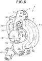
- FIG. 6 is a perspective view depicting the throttle opening sensor and the set plate
- FIG. 7 is an exploded view of the throttle opening sensor.
- the set plate 7 includes a front plate 71 as a front half body of the set plate 7 and a rear plate 72 as a rear half body of the set plate 7.
- the front plate 71 of the set plate 7 has an upper portion 71a and a lower portion 71b both fixed to the sensor case 41 by screws 74.
- the rear plate 72 is mounted to the front plate 71.
- the rear plate 72 has a lower portion 72b inserted into an opening portion 71d of the front plate 71, and an upper portion 72a fixed to the upper portion 71a of the front plate 71 by a screw 73.
- An arcuate portion 71c which serves as a halved tubular portion of the set plate 7, is provided between the upper portion 71a and the lower portion 71b which are plate portions of the front plate 71. Further, an arcuate portion 72c, which serves as another halved tubular portion of the set plate 7, is provided between the upper portion 72a and the lower portion 72b which are plate portions of the rear plate 72.
- the handlebar 2 can therefore be disposed between the arcuate portions 71c and 72c disposed at respective central portions of the front plate 71 and the rear plate 72, whereby the handlebar 2 is held by the set plate 7.
- the arcuate portion 72c of the rear plate 72 has a protrusion 72d formed therein.
- the throttle opening sensor 4 can be mounted at a predetermined position of the handlebar 2.
- the upper portion 71a of the front plate 71 is offset with respect to the lower portion 71b in the front-rear direction. As depicted in FIG. 4 , in a state in which the set plate 7 is mounted to the handlebar 2, the front plate 71 makes the upper portion 71a offset rearward and the lower portion 71b offset forward. That is, the lower portion 71b is positioned in front of a straight line L1 along the upper portion 71a in a side view.
- the connector 62a of the second switch 62 extends forward, extends downward and then further extends forward. This avoids interference between the connector 62a and the arcuate portion 72c of the rear plate 72.
- the connector 63a of the start switch 63 extends forward and reaches to a position below the arcuate portion 72c of the rear plate 72.
- the connector 63a is disposed at a position overlapping the handlebar 2 as viewed from above, and disposed at a position overlapping the lower portion 71b of the front plate 71 as viewed from the front side. That is, the connector 63a is disposed utilizing a space generated by offsetting the lower portion 71b of the front plate 71 forward.
- a rotor 43, a magnet 44 and a return spring 45 are arranged inside the sensor case 41 of the throttle opening sensor 4, and a cover 42 is mounted to the sensor case 41 and fixed by screws 48.
- the rotor 43 is engaged with the throttle pipe 5 and rotated integrally with the throttle pipe 5.
- the magnet 44 is mounted to the rotor 43.
- the return spring 45 is engaged with a side of the rotor 43 opposite to the side engaged with the throttle pipe 5.
- the return spring 45 biases the rotor 43 in a direction of closing the throttle pipe 5, i.e. clockwise as viewed from the left side.
- a circuit board 46 is attached to a left side surface on the front side of the sensor case 41.
- the circuit board 46 is in a vertically-long plate shape and has a surface attached to the sensor case 41, the surface being parallel to a surface on which a circuit is formed.
- the connector 47 is connected to the circuit board 46 via a cable.
- a cable for connecting to the connector 47 is attached to an upper portion of the circuit board 46 and is vertically routed from an upper portion to a lower portion of the throttle opening sensor 4. This allows the cable connecting the connector 47 and the circuit board 46 to be made long in the throttle opening sensor 4, thereby allowing curves of the cable to be gentle.
- the circuit board 46 and the magnet 44 mounted to the rotor 43 configure a detector that detects a displacement of the rotor 43.
- the magnet 44 is formed in an arcuate shape along the handlebar 2 and disposed in a front portion of the sensor case 41.
- the step portion 41a recessed inward is formed in a rear portion of the sensor case 41 opposite to the front portion.
- the magnet 44 of the rotor 43 and the circuit board 46 are disposed on the front side in the throttle opening sensor 4 in the front-rear direction of the motorcycle.
- the magnet 44 is in an arcuate shape having the central angle of approximately 90 degrees or less, and the opening of a throttle pipe of a motorcycle is generally 90 degrees or less. Accordingly, by disposing the magnet 44 on the front side, even when the throttle pipe 5 is rotated, the magnet 44 remains on the front side of the sensor case 41. The space required behind the rotor 43 is thus reduced. Further, by mounting the circuit board 46 on the front side of the sensor case 41 along with the magnet 44, the rear portion of the sensor case 41 can be reduced in size.
- the switch group can be disposed closely to the rear portion of the sensor case 41 without influencing the mechanism and actions of the throttle opening sensor 4. Further, by bringing the second switch 62 close to the step portion 41a when the second switch 62 is assembled to the switch cover 1c, the range within which the second switch 62 can be moved is increased.
- step portion 41a in the rear portion of the sensor case 41 enhances the rigidity of the rear portion of the sensor case 41.
- the set plate 7 for mounting the sensor case 41 to the handlebar 2 is configured by the front plate 71 and the rear plate 72, the set plate 7 can be easily formed by press-molding a metal plate.
- the thickness of the set plate 7 can be made thin, and a space occupied by the set plate 7 in a space in the vicinity of the throttle opening sensor 4 can be reduced.
- the upper portion 71a and the lower portion 71b are offset from each other in the front-rear direction. This increases a space in front of the upper portion 71a and a space behind the lower portion 71b. In a space inside the handle cover 1, a large space can be secured in which the switch group is disposed behind the lower portion 71b.
- the throttle opening detecting apparatus for a saddle riding vehicle which includes the handle cover 1, the first switch 61, the second switch 62, and the start switch 63, and the handlebar 2 and in which the throttle opening sensor 4 fixed to the handlebar 2 and detecting a displacement of the rotor 43 inside the sensor case 41 is included in the handle cover 1, at least one of the first switch 61, the second switch 62, and the start switch 63 can be disposed at a position facing the sensor case 41 inside the handle cover 1, and the sensor case 41 can have the step portion 41a formed on a side surface thereof on a side opposite to the throttle pipe 5 rotated integrally with the rotor 43.
- the throttle opening sensor 4 can be configured in a compact manner, and therefore, the switch group and the throttle opening sensor 4 can be appropriately arranged even in the handle cover 1.
- step portion 41a can be disposed behind the throttle pipe 5.
- the switch group and the throttle opening sensor 4 can be appropriately arranged even in the handle cover 1.
- the switch group can be disposed closely to the throttle opening sensor 4, enabling the operator to easily operate the switch group.
- the step portion 41a enhances the rigidity of a circumferential surface of the sensor case 41, which leads to reduction in thickness of the rear portion of the sensor case 41.
- the rear portion of the sensor case 41 can be further configured in a compact manner.
- step portion 41a can be formed in an arcuate shape.
- the sensor case 41 can be made compact so as to match the circular shape of the rotor 43.
- a space for arranging the switch group in the vertical direction behind the sensor case 41 can be secured.
- the set plate 7 holding the handlebar 2 may be connected to the sensor case 41, and the set plate 7 may be configured by two divided parts, which are divided in the front-rear direction, that is, the front plate 71 and the rear plate 72.
- the set plate 7 may have at the center thereof the arcuate portions 71c and 72c between which the handlebar 2 is fitted in, and at opposite ends of the arcuate portions 71c and 72c the upper portion 71a and the lower portion 71b of the front plate 71 to be connected to the sensor case 41.
- the upper portion 71a and the lower portion 71b may be disposed offset from each other in the front-rear direction with the handlebar 2 interposed therebetween.
- the throttle opening sensor 4 including the set plate 7 and the switch group can be configured in a compact manner.
- first switch 61, the second switch 62, and the start switch 63 may be disposed on an opposite side, with respect to the handlebar 2, to the side of the offset of the upper portion 71a and the lower portion 71b of the front plate 71.
- the switch group can be appropriately disposed.
- At least one of the connectors 61a, 62a, and 63a of the first switch 61, the second switch 62, and the start switch 63 may overlap the lower portion 71b of the front plate 71 as viewed from the front side.
- the lower portion 71b of the front plate 71 of the set plate 7 may be offset forward, and at least one of the connectors 61a, 62a, and 63a of the first switch 61, the second switch 62, and the start switch 63 may be disposed behind the lower portion 71b.
- circuit board 46 and the magnet 44 which are members for detecting a displacement of the rotor 43 of the throttle opening sensor 4 may be disposed on an opposite side to the step portion 41a with respect to the handlebar 2.
- circuit board 46 and the magnet 44 which are members for detecting a displacement of the rotor 43 may be disposed in front of the handlebar 2.
- circuit board 46 and the magnet 44 which are members for detecting a displacement of the rotor 43 are disposed between the handlebar 2 and the brake lever 3, and thus, the circuit board 46 and the magnet 44 are hardly affected by an external force.
- the present invention is not limited thereto.
- the present invention is applicable to any types of saddle riding vehicles including three-wheel saddle riding vehicles having two front or rear wheels and saddle riding vehicles having four or more wheels.
- a throttle opening detecting apparatus for a saddle riding vehicle which includes a handle cover 1, a handle switch group (61, 62, 63), and a handlebar 2, and in which a throttle opening sensor 4 fixed to the handlebar 2 and configured to detect a displacement of a rotor 43 in a sensor case 41 is included in the handle cover 1, at least one switch of the handle switch group (61, 62, 63) is disposed at a position facing the sensor case 41 in the handle cover 1, and the sensor case 41 has a step portion 41a formed on a side surface thereof on a side opposite to a throttle pipe 5 rotated integrally with the rotor 43.
Landscapes
- Engineering & Computer Science (AREA)
- Mechanical Engineering (AREA)
- Chemical & Material Sciences (AREA)
- Combustion & Propulsion (AREA)
- General Engineering & Computer Science (AREA)
- Steering Devices For Bicycles And Motorcycles (AREA)
- Control Of Throttle Valves Provided In The Intake System Or In The Exhaust System (AREA)
- Automatic Cycles, And Cycles In General (AREA)
Abstract
Description
- The present invention relates to a throttle opening detecting apparatus for a saddle riding vehicle.
- In a motorcycle, an opening sensor is used for detecting a throttle opening. The opening sensor is mounted to a handlebar and detects a displacement by rotation of a rotor fixed to a throttle pipe.
- As disclosed in Patent Document 1, a switch group is mounted to the handlebar together with the opening sensor.
- [Patent Document 1]
Japanese Patent Laid-open No.2017-133449 - A handlebar has an opening sensor configured integrally with a throttle pipe mounted thereto and a switch group mounted thereto. Accordingly, the switch group is disposed with respect to the throttle pipe with the opening sensor interposed therebetween.
- In order for an operator of the motorcycle to operate the switch group while driving, it is necessary that the switch group be appropriately disposed in a range in which a finger of the operator can reach in a state in which the operator grasps the throttle grip.
- Further, in a motorcycle having such a design as to cover a handlebar with a cowl or the like, it is demanded to configure a switch group as well as an opening sensor in a compact manner.
- It is also demanded to make the opening sensor hardly affected by an external force such as a magnetic force.
- The present invention has been made in view of the foregoing circumstances, and it is an object of the present invention to provide a throttle opening detecting apparatus for a saddle riding vehicle in which a throttle opening sensor and a switch group attached to a handlebar are configured in a compact manner and the opening sensor is hardly affected by an external force such as a magnetic force.
- According to the present invention, there is provided a throttle opening detecting apparatus for a saddle riding vehicle which includes a handle cover (1), a handle switch group (61, 62, 63), and a handlebar (2), and in which a throttle opening sensor (4) fixed to the handlebar (2) and detecting a displacement of a rotor (43) inside a sensor case (41) is included in the handle cover (1). In the throttle opening detecting apparatus, at least one switch of the handle switch group (61, 62, 63) is disposed at a position facing the sensor case (41) in the handle cover (1), and the sensor case (41) has a step portion (41a) formed on a side surface thereof on a side opposite to a throttle pipe (5) rotated integrally with the rotor (43).
- Further, in the invention described above, the step portion (41a) may be disposed behind the throttle pipe (5).
- Further, in the invention described above, the step portion (41a) may be formed in an arcuate shape.
- Further, in the invention described above, a set plate (7) holding the handlebar (2) may be connected to the sensor case (41), the set plate (7) may include two divided parts divided in a front-rear direction, that is, a front half body (71) and a rear half body (72), the set plate (7) may have at a center thereof halved tubular portions (71c, 72c) between which the handlebar (2) is fitted, and at opposite ends of the halved tubular portions (71c, 72c) plate portions (71a, 71b) to be connected to the sensor case (41), and the plate portions (71a, 71b) may be disposed offset from each other in the front-rear direction with the handlebar (2) interposed therebetween.
- Further, in the invention described above, at least some switches of the handle switch group (61, 62, 63) may be disposed on an opposite side, with respect to the handlebar (2), to a side of the offset of the plate portions (71a, 71b).
- Further, in the invention described above, at least one of connectors (61a, 62a, 63a) of the handle switch group (61, 62, 63) may overlap the plate portion (71b) as viewed from a front side.
- Further, in the invention described above, the plate portion (71b) of the set plate (7) may be offset forward, and at least one of connectors (61a, 62a, 63a) of the handle switch group (61, 62, 63) may be disposed behind the plate portion (71b).
- Further, in the invention described above, members (46, 44) detecting a displacement of the rotor (43) of the throttle opening sensor (4) may be disposed on an opposite side to the step portion (41a) with the handlebar (2) interposed therebetween.
- Further, in the invention described above, the members (46, 44) detecting a displacement of the rotor (43) may be disposed in front of the handlebar (2).
- According to the present invention, a throttle opening detecting apparatus for a saddle riding vehicle includes a handle cover, a handle switch group, and a handlebar, and in which a throttle opening sensor fixed to the handlebar and detecting a displacement of a rotor in a sensor case is included in the handle cover, at least one switch of the handle switch group is disposed at a position facing the sensor case in the handle cover, and the sensor case has a step portion formed on a side surface thereof on a side opposite to a throttle pipe rotated integrally with the rotor.
- With this configuration, even in a limited space inside the handle cover, the step portion enables appropriate disposing of the switches, and the sensor case within a range within which operability for a rider is secured.
- Further, in the invention described above, the step portion may be disposed behind the throttle pipe.
- With this configuration, the switches are disposed on the side of the operator, and the step portion is formed on the reverse side of the switches, thereby allowing a clearance for moving the switches on assembling or removing the switches to be generated.
- Further, in the invention described above, the step portion may be formed in an arcuate shape.
- With this configuration, a clearance for the multiple switches can be generated.
- Further, in the invention described above, a set plate holding the handlebar may be connected to the sensor case, the set plate may include two divided parts divided in a front-rear direction, that is, a front half body and a rear half body, the set plate may have at a center thereof halved tubular portions between which the handlebar is fitted in, and at opposite ends of the halved tubular portions plate portions to be connected to the sensor case, and the plate portions may be disposed offset from each other in the front-rear direction with the handlebar interposed therebetween.
- With this configuration, even in a limited space inside the handle cover, the switches and the throttle opening sensor can be appropriately disposed within a range within which operability for the rider is secured.
- Further, in the invention described above, at least some switches of the handle switch group may be disposed on an opposite side, with respect to the handlebar, to a side of the offset of the plate portions.
- With this configuration, in the proximity of the sensor case, a space for accommodating other components can be appropriately secured.
- Further, in the invention described above, at least one of connectors of the handle switch group may overlap the plate portion as viewed from a front side.
- With this configuration, space-saving arrangement of the connectors can be achieved.
- Further, in the invention described above, the plate portion of the set plate may be offset forward, and at least one of connectors of the handle switch group may be disposed behind the plate portion.
- With this configuration, terminals to be connected to the connectors can be disposed in a space generated by offsetting the plate. Therefore, even in a limited space inside the handle cover, it is easy to secure a space for connecting terminals.
- Further, in the invention described above, members detecting a displacement of the rotor of the throttle opening sensor may be disposed on an opposite side to the step portion with the handlebar interposed therebetween.
- With this configuration, even in a limited space inside the handle cover, the switches and the throttle opening sensor can be appropriately disposed within a range within which operability for the rider is secured.
- Further, in the invention described above, the throttle opening sensor may be disposed in front of the handlebar.
- The throttle opening sensor can be disposed between the brake lever and the handlebar so as to keep a distance from the outside, and thus, the throttle opening sensor is hardly affected by an external force.
-
-
FIG. 1 is a perspective view depicting a configuration of the vicinity of a handlebar of a motorcycle according to an embodiment of the present invention. -
FIG. 2 is a view depicting a configuration of the vicinity of a throttle pipe as viewed from the rear side. -
FIG. 3 is a perspective view depicting the configuration of the vicinity of the throttle pipe as viewed from the front side. -
FIG. 4 is a left side view depicting a mounting structure of a throttle opening sensor. -
FIG. 5 is a cross-sectional view taken along line V-V inFIG. 2 . -
FIG. 6 is a perspective view depicting the throttle opening sensor and a set plate. -
FIG. 7 is an exploded view of the throttle opening sensor. - An embodiment of the present invention will be described below with reference to the accompanying drawings.
-
FIG. 1 is a perspective view depicting a configuration of the vicinity of a handlebar of a motorcycle according to an embodiment of the present invention. In the drawings, symbol FR indicates the front direction of a vehicle body, symbol UP indicates the upward direction of the vehicle body, and symbol RH indicates the rightward direction of the vehicle body. - A
handlebar 2 of the motorcycle is covered with a handle cover 1. On a right end portion of thehandlebar 2, athrottle pipe 5 is mounted together with athrottle opening sensor 4. Thethrottle pipe 5 has agrip 21 mounted on an outer peripheral surface thereof. - A
brake lever 3 is disposed in front of thegrip 21 and mounted to thehandlebar 2 together with amaster cylinder 31. - The
throttle opening sensor 4 and themaster cylinder 31 are arranged inside the handle cover 1, and a front portion of thethrottle opening sensor 4 is covered with asensor portion cover 1b. - This prevents devices disposed inside the handle cover 1 from being exposed to rainwater and dust. Further, the handle cover 1 allows air to flow smoothly in the vicinity of the
handlebar 2. -
FIG. 2 is a view depicting the configuration of the vicinity of the throttle pipe as viewed from the rear side, andFIG. 3 is a perspective view depicting the configuration of the vicinity of the throttle pipe as viewed from the front side.FIG. 4 is a left side view depicting a mounting structure of the throttle opening sensor, andFIG. 5 is a cross-sectional view taken along line V-V inFIG. 2 . - The handle cover 1 includes at a right end portion thereof a
switch cover 1c in which a handle switch group of the motorcycle is arranged. The handle switch group includes afirst switch 61, asecond switch 62, and astart switch 63. - The
first switch 61 is a switch that can be used as a dimmer switch, a kill switch, or the like. Thesecond switch 62 is a switch that can be used as a light switch, position switch, or a hazard-warning-light switch. - It should be noted that the
start switch 63 is used on starting an engine. - The
throttle opening sensor 4 is disposed inside the handle cover 1 and in front of theswitch cover 1c. Theswitch cover 1c covers a rear surface of thethrottle opening sensor 4 ranging from an upper portion to a lower portion of thethrottle opening sensor 4. - As depicted in
FIG. 5 , theswitch cover 1c is disposed such that a rear surface of theswitch cover 1c is slightly oriented to the right side. This causes the switch group arranged in theswitch cover 1c to be disposed closely to the wrist of the right hand of an operator, enabling the operator to easily operate the switch group with his/her thumb. - The
throttle pipe 5 is mounted to thethrottle opening sensor 4 which can detect a rotation amount of thethrottle pipe 5. - As depicted in
FIG. 3 , a front side and a left side surface portion of thethrottle opening sensor 4 are covered with thesensor portion cover 1b, and aconnector 47 of thethrottle opening sensor 4 protrudes from a lower portion of a left side surface of thesensor portion cover 1b toward a left and obliquely lower side. A control unit (not depicted) of the motorcycle is connected to theconnector 47 via a cable and recognizes the rotation amount of thethrottle pipe 5. - The
first switch 61, thesecond switch 62, and thestart switch 63 are disposed behind thethrottle opening sensor 4, and thesecond switch 62 is disposed at a position facing thethrottle opening sensor 4 in a front-rear direction. Asensor case 41 of thethrottle opening sensor 4 has astep portion 41a formed at a left rear portion thereof. - The
sensor case 41 has a rear portion formed in a cylindrical shape centered at thehandlebar 2, with an outer peripheral surface of the rear portion on an outer side in a vehicle width direction larger than the outer peripheral surface on an inner side. This makes thestep portion 41a in an arcuate shape in the rear portion of thesensor case 41. - It should be noted that, since the
sensor case 41 has thestep portion 41a in the rear portion thereof, thestep portion 41a is disposed outside thethrottle pipe 5 with respect to thehandlebar 2 as a center. Accordingly, thestep portion 41a is positioned behind thethrottle pipe 5. - Further, operating portions for the
first switch 61, thesecond switch 62, and thestart switch 63 are disposed outside thethrottle opening sensor 4 with respect to thehandlebar 2 as a center. The operating portions for thefirst switch 61, thesecond switch 62, and thestart switch 63 are exposed from theswitch cover 1c. Accordingly, the switch group can be operated externally of the handle cover 1. -
Connectors first switch 61 and thesecond switch 62 respectively protrude from theswitch cover 1c toward thehandlebar 2. Aconnector 63a of thestart switch 63 extends rearward. It should be noted that, inFIG. 5 , aconnector 63b is theconnector 63a with its cover removed. - The
throttle opening sensor 4 is mounted to thehandlebar 2 by aset plate 7.
FIG. 6 is a perspective view depicting the throttle opening sensor and the set plate, andFIG. 7 is an exploded view of the throttle opening sensor. - The
set plate 7 includes afront plate 71 as a front half body of theset plate 7 and arear plate 72 as a rear half body of theset plate 7. Thefront plate 71 of theset plate 7 has anupper portion 71a and alower portion 71b both fixed to thesensor case 41 byscrews 74. - As depicted in
FIG. 4 andFIG. 6 , therear plate 72 is mounted to thefront plate 71. Therear plate 72 has alower portion 72b inserted into anopening portion 71d of thefront plate 71, and anupper portion 72a fixed to theupper portion 71a of thefront plate 71 by ascrew 73. - An
arcuate portion 71c, which serves as a halved tubular portion of theset plate 7, is provided between theupper portion 71a and thelower portion 71b which are plate portions of thefront plate 71. Further, anarcuate portion 72c, which serves as another halved tubular portion of theset plate 7, is provided between theupper portion 72a and thelower portion 72b which are plate portions of therear plate 72. - The
handlebar 2 can therefore be disposed between thearcuate portions front plate 71 and therear plate 72, whereby thehandlebar 2 is held by theset plate 7. - It should be noted that the
arcuate portion 72c of therear plate 72 has aprotrusion 72d formed therein. By inserting theprotrusion 72d in a positioning hole (not depicted) of thehandlebar 2, thethrottle opening sensor 4 can be mounted at a predetermined position of thehandlebar 2. - The
upper portion 71a of thefront plate 71 is offset with respect to thelower portion 71b in the front-rear direction. As depicted inFIG. 4 , in a state in which theset plate 7 is mounted to thehandlebar 2, thefront plate 71 makes theupper portion 71a offset rearward and thelower portion 71b offset forward. That is, thelower portion 71b is positioned in front of a straight line L1 along theupper portion 71a in a side view. - In a lower portion of the
switch cover 1c, theconnector 62a of thesecond switch 62 extends forward, extends downward and then further extends forward. This avoids interference between theconnector 62a and thearcuate portion 72c of therear plate 72. - In a lower portion of the
switch cover 1c, theconnector 63a of thestart switch 63 extends forward and reaches to a position below thearcuate portion 72c of therear plate 72. - The
connector 63a is disposed at a position overlapping thehandlebar 2 as viewed from above, and disposed at a position overlapping thelower portion 71b of thefront plate 71 as viewed from the front side. That is, theconnector 63a is disposed utilizing a space generated by offsetting thelower portion 71b of thefront plate 71 forward. - As depicted in
FIG. 7 , arotor 43, amagnet 44 and areturn spring 45 are arranged inside thesensor case 41 of thethrottle opening sensor 4, and acover 42 is mounted to thesensor case 41 and fixed byscrews 48. - The
rotor 43 is engaged with thethrottle pipe 5 and rotated integrally with thethrottle pipe 5. Themagnet 44 is mounted to therotor 43. Thereturn spring 45 is engaged with a side of therotor 43 opposite to the side engaged with thethrottle pipe 5. Thereturn spring 45 biases therotor 43 in a direction of closing thethrottle pipe 5, i.e. clockwise as viewed from the left side. - A
circuit board 46 is attached to a left side surface on the front side of thesensor case 41. Thecircuit board 46 is in a vertically-long plate shape and has a surface attached to thesensor case 41, the surface being parallel to a surface on which a circuit is formed. - The
connector 47 is connected to thecircuit board 46 via a cable. Specifically, a cable for connecting to theconnector 47 is attached to an upper portion of thecircuit board 46 and is vertically routed from an upper portion to a lower portion of thethrottle opening sensor 4. This allows the cable connecting theconnector 47 and thecircuit board 46 to be made long in thethrottle opening sensor 4, thereby allowing curves of the cable to be gentle. - In the
throttle opening sensor 4, thecircuit board 46 and themagnet 44 mounted to therotor 43 configure a detector that detects a displacement of therotor 43. Themagnet 44 is formed in an arcuate shape along thehandlebar 2 and disposed in a front portion of thesensor case 41. - By disposing the
circuit board 46 and themagnet 44 in the front portion of thesensor case 41, thestep portion 41a recessed inward is formed in a rear portion of thesensor case 41 opposite to the front portion. - Now, operations according to the embodiment of the present invention will be described below.
- As depicted in
FIG. 7 , themagnet 44 of therotor 43 and thecircuit board 46 are disposed on the front side in thethrottle opening sensor 4 in the front-rear direction of the motorcycle. Themagnet 44 is in an arcuate shape having the central angle of approximately 90 degrees or less, and the opening of a throttle pipe of a motorcycle is generally 90 degrees or less. Accordingly, by disposing themagnet 44 on the front side, even when thethrottle pipe 5 is rotated, themagnet 44 remains on the front side of thesensor case 41. The space required behind therotor 43 is thus reduced. Further, by mounting thecircuit board 46 on the front side of thesensor case 41 along with themagnet 44, the rear portion of thesensor case 41 can be reduced in size. - Since the
step portion 41a is disposed in the rear portion of thesensor case 41, the switch group can be disposed closely to the rear portion of thesensor case 41 without influencing the mechanism and actions of thethrottle opening sensor 4. Further, by bringing thesecond switch 62 close to thestep portion 41a when thesecond switch 62 is assembled to theswitch cover 1c, the range within which thesecond switch 62 can be moved is increased. - In addition, forming the
step portion 41a in the rear portion of thesensor case 41 enhances the rigidity of the rear portion of thesensor case 41. - Since the
set plate 7 for mounting thesensor case 41 to thehandlebar 2 is configured by thefront plate 71 and therear plate 72, theset plate 7 can be easily formed by press-molding a metal plate. - Further, compared with a case in which a plastic material is used, the thickness of the
set plate 7 can be made thin, and a space occupied by theset plate 7 in a space in the vicinity of thethrottle opening sensor 4 can be reduced. - In the
front plate 71 of theset plate 7, theupper portion 71a and thelower portion 71b are offset from each other in the front-rear direction. This increases a space in front of theupper portion 71a and a space behind thelower portion 71b. In a space inside the handle cover 1, a large space can be secured in which the switch group is disposed behind thelower portion 71b. - As described above, according to the embodiment to which the present invention is applied, in the throttle opening detecting apparatus for a saddle riding vehicle which includes the handle cover 1, the
first switch 61, thesecond switch 62, and thestart switch 63, and thehandlebar 2 and in which thethrottle opening sensor 4 fixed to thehandlebar 2 and detecting a displacement of therotor 43 inside thesensor case 41 is included in the handle cover 1, at least one of thefirst switch 61, thesecond switch 62, and thestart switch 63 can be disposed at a position facing thesensor case 41 inside the handle cover 1, and thesensor case 41 can have thestep portion 41a formed on a side surface thereof on a side opposite to thethrottle pipe 5 rotated integrally with therotor 43. - With this configuration, the
throttle opening sensor 4 can be configured in a compact manner, and therefore, the switch group and thethrottle opening sensor 4 can be appropriately arranged even in the handle cover 1. - Further, the
step portion 41a can be disposed behind thethrottle pipe 5. - With this configuration, the switch group and the
throttle opening sensor 4 can be appropriately arranged even in the handle cover 1. In addition, the switch group can be disposed closely to thethrottle opening sensor 4, enabling the operator to easily operate the switch group. Further, thestep portion 41a enhances the rigidity of a circumferential surface of thesensor case 41, which leads to reduction in thickness of the rear portion of thesensor case 41. As a result, the rear portion of thesensor case 41 can be further configured in a compact manner. - Further, the
step portion 41a can be formed in an arcuate shape. - With this configuration, the
sensor case 41 can be made compact so as to match the circular shape of therotor 43. In addition, a space for arranging the switch group in the vertical direction behind thesensor case 41 can be secured. - Further, the
set plate 7 holding thehandlebar 2 may be connected to thesensor case 41, and theset plate 7 may be configured by two divided parts, which are divided in the front-rear direction, that is, thefront plate 71 and therear plate 72. Theset plate 7 may have at the center thereof thearcuate portions handlebar 2 is fitted in, and at opposite ends of thearcuate portions upper portion 71a and thelower portion 71b of thefront plate 71 to be connected to thesensor case 41. Theupper portion 71a and thelower portion 71b may be disposed offset from each other in the front-rear direction with thehandlebar 2 interposed therebetween. - With this configuration, even in the handle cover 1, the
throttle opening sensor 4 including the setplate 7 and the switch group can be configured in a compact manner. - Further, at least some of the
first switch 61, thesecond switch 62, and thestart switch 63 may be disposed on an opposite side, with respect to thehandlebar 2, to the side of the offset of theupper portion 71a and thelower portion 71b of thefront plate 71. - With this configuration, even in the handle cover 1, the switch group can be appropriately disposed.
- Further, at least one of the
connectors first switch 61, thesecond switch 62, and thestart switch 63 may overlap thelower portion 71b of thefront plate 71 as viewed from the front side. - With this configuration, interference between the connectors of the switch group and the
set plate 7 can be avoided, the space for disposing the switch group can be secured, and mounting work can be facilitated. - Further, the
lower portion 71b of thefront plate 71 of theset plate 7 may be offset forward, and at least one of theconnectors first switch 61, thesecond switch 62, and thestart switch 63 may be disposed behind thelower portion 71b. - With this configuration, interference between the connectors of the switch group and the
set plate 7 can be avoided, the space for disposing the switch group can be secured, and mounting work can be facilitated. - Further, the
circuit board 46 and themagnet 44 which are members for detecting a displacement of therotor 43 of thethrottle opening sensor 4 may be disposed on an opposite side to thestep portion 41a with respect to thehandlebar 2. - With this configuration, in the proximity of the
throttle opening sensor 4, a space for disposing the switch group on the side of thestep portion 41a can be secured, and the switch group can be disposed closely to thethrottle opening sensor 4. - This allows the switch group to be brought close to the
throttle pipe 5, so that the switch group can be easily operated while at the same time operating thethrottle pipe 5. - Further, the
circuit board 46 and themagnet 44 which are members for detecting a displacement of therotor 43 may be disposed in front of thehandlebar 2. - With this configuration, the
circuit board 46 and themagnet 44 which are members for detecting a displacement of therotor 43 are disposed between thehandlebar 2 and thebrake lever 3, and thus, thecircuit board 46 and themagnet 44 are hardly affected by an external force. - The embodiment described above merely represents one aspect of the present invention, and modifications and applications may be arbitrarily made without departing from the spirit the present invention.
- While the embodiment has been described citing a motorcycle as an example of saddle riding vehicles, the present invention is not limited thereto. The present invention is applicable to any types of saddle riding vehicles including three-wheel saddle riding vehicles having two front or rear wheels and saddle riding vehicles having four or more wheels.
- It is an object of the present invention to provide a throttle opening detecting apparatus for a saddle riding vehicle in which a throttle opening sensor and a switch group mounted to a handlebar are configured in a compact manner and the opening sensor is hardly affected by an external force such as a magnetic force.
- In a throttle opening detecting apparatus for a saddle riding vehicle which includes a handle cover 1, a handle switch group (61, 62, 63), and a
handlebar 2, and in which athrottle opening sensor 4 fixed to thehandlebar 2 and configured to detect a displacement of arotor 43 in asensor case 41 is included in the handle cover 1, at least one switch of the handle switch group (61, 62, 63) is disposed at a position facing thesensor case 41 in the handle cover 1, and thesensor case 41 has astep portion 41a formed on a side surface thereof on a side opposite to athrottle pipe 5 rotated integrally with therotor 43. -
- 1 Handle cover
- 2 Handlebar
- 3 Brake lever
- 4 Throttle opening sensor
- 5 Throttle pipe
- 7 Set plate
- 41 Sensor case
- 41a Step portion
- 42 Cover
- 43 Rotor
- 44 Magnet
- 45 Return spring
- 46 Circuit board
- 47 Connector
- 61 First switch
- 61a Connector
- 62 Second switch
- 62a Connector
- 63 Start switch
- 63a Connector
- 71 Front plate
- 71a Upper portion
- 71b Lower portion
- 71c Arcuate portion
- 71d Opening portion
- 72 Rear plate
- 72a Upper portion
- 72b Lower portion
- 72c Arcuate portion
- 72d Protrusion
Claims (9)
- A throttle opening detecting apparatus for a saddle riding vehicle which includes a handle cover (1), a handle switch group (61, 62, 63), and a handlebar (2), and
in which a throttle opening sensor (4) fixed to the handlebar (2) and detecting a displacement of a rotor (43) in a sensor case (41) is included in the handle cover (1), characterized in that
at least one switch of the handle switch group (61, 62, 63) is disposed at a position facing the sensor case (41) in the handle cover (1), and
the sensor case (41) has a step portion (41a) formed on a side surface thereof on a side opposite to a throttle pipe (5) rotated integrally with the rotor (43). - The throttle opening detecting apparatus for a saddle riding vehicle according to claim 1, wherein the step portion (41a) is disposed behind the throttle pipe (5) .
- The throttle opening detecting apparatus for a saddle riding vehicle according to claim 1 or 2, wherein the step portion (41a) is formed in an arcuate shape.
- The throttle opening detecting apparatus for a saddle riding vehicle according to any one of claims 1 to 3,
wherein a set plate (7) holding the handlebar (2) is connected to the sensor case (41),
the set plate (7) includes two divided parts divided in a front-rear direction, that is, a front half body (71) and a rear half body (72),
the set plate (7) has at a center thereof halved tubular portions (71c, 72c) between which the handlebar (2) is fitted in, and at opposite ends of the halved tubular portions (71c, 72c) plate portions (71a, 71b) to be connected to the sensor case (41), and
the plate portions (71a, 71b) are disposed offset from each other in the front-rear direction with the handlebar (2) interposed therebetween. - The throttle opening detecting apparatus for a saddle riding vehicle according to claim 4, wherein at least some switches of the handle switch group (61, 62, 63) are disposed on an opposite side, with respect to the handlebar (2), to a side of the offset of the plate portions (71a, 71b).
- The throttle opening detecting apparatus for a saddle riding vehicle according to claim 5, wherein at least one of connectors (61a, 62a, 63a) of the handle switch group (61, 62, 63) overlaps the plate portion (71b) as viewed from a front side.
- The throttle opening detecting apparatus for a saddle riding vehicle according to claim 4, wherein the plate portion (71b) of the set plate (7) is offset forward, and at least one of connectors (61a, 62a, 63a) of the handle switch group (61, 62, 63) is disposed behind the plate portion (71b).
- The throttle opening detecting apparatus for a saddle riding vehicle according to any one of claims 1 to 7, wherein members (46, 44) detecting a displacement of the rotor (43) of the throttle opening sensor (4) are disposed on an opposite side to the step portion (41a) with the handlebar (2) interposed therebetween.
- The throttle opening detecting apparatus for a saddle riding vehicle according to claim 8, wherein the members (46, 44) detecting a displacement of the rotor (43) are disposed in front of the handlebar (2).
Applications Claiming Priority (1)
| Application Number | Priority Date | Filing Date | Title |
|---|---|---|---|
| JP2018045267A JP6655641B2 (en) | 2018-03-13 | 2018-03-13 | Throttle opening detection device for saddle type vehicle |
Publications (2)
| Publication Number | Publication Date |
|---|---|
| EP3546329A1 true EP3546329A1 (en) | 2019-10-02 |
| EP3546329B1 EP3546329B1 (en) | 2021-07-14 |
Family
ID=65635463
Family Applications (1)
| Application Number | Title | Priority Date | Filing Date |
|---|---|---|---|
| EP19159825.9A Active EP3546329B1 (en) | 2018-03-13 | 2019-02-27 | Throttle opening detecting apparatus for saddle riding vehicle |
Country Status (4)
| Country | Link |
|---|---|
| US (1) | US10703432B2 (en) |
| EP (1) | EP3546329B1 (en) |
| JP (1) | JP6655641B2 (en) |
| CN (1) | CN110273764B (en) |
Families Citing this family (6)
| Publication number | Priority date | Publication date | Assignee | Title |
|---|---|---|---|---|
| JP7337340B2 (en) * | 2019-06-04 | 2023-09-04 | 朝日電装株式会社 | throttle grip device |
| US20230026992A1 (en) * | 2019-12-10 | 2023-01-26 | Hirschmann Automotive Gmbh | Throttle with integrated switch block |
| CN113513417B (en) * | 2020-04-10 | 2023-11-24 | 本田技研工业株式会社 | throttle device |
| JP7553909B2 (en) * | 2020-12-04 | 2024-09-19 | 朝日電装株式会社 | Throttle control device |
| JP7750470B2 (en) * | 2020-12-04 | 2025-10-07 | 朝日電装株式会社 | Throttle operation device |
| JP2026000715A (en) * | 2024-06-18 | 2026-01-06 | 朝日電装株式会社 | Throttle grip device |
Citations (4)
| Publication number | Priority date | Publication date | Assignee | Title |
|---|---|---|---|---|
| US20130240285A1 (en) * | 2012-03-15 | 2013-09-19 | Yamaha Hatsudoki Kabushiki Kaisha | Saddle riding type vehicle |
| DE102013205035A1 (en) * | 2012-03-28 | 2013-10-02 | Honda Motor Co., Ltd. | Harness wiring structure of seat vehicle e.g. motorcycle, has handlebar-side terminal that is wired toward front lower side of chassis, so that wire harness is wired between handlebar-side terminal and vehicle chassis side terminal |
| JP2017133449A (en) | 2016-01-29 | 2017-08-03 | 本田技研工業株式会社 | Throttle opening detection device for saddle-ride type vehicles |
| US20170327172A1 (en) * | 2016-05-16 | 2017-11-16 | Honda Motor Co., Ltd. | Wiring structure of grip heater |
Family Cites Families (13)
| Publication number | Priority date | Publication date | Assignee | Title |
|---|---|---|---|---|
| JPH11344302A (en) * | 1998-05-29 | 1999-12-14 | Ntn Corp | Rotating angle detecting apparatus |
| JP3842024B2 (en) * | 2000-08-07 | 2006-11-08 | 本田技研工業株式会社 | Handle switch mounting structure |
| US6377016B1 (en) * | 2001-01-23 | 2002-04-23 | Samuel Y. T. Strong | Handlebar accelerator for an electrical bicycle |
| JP4850606B2 (en) * | 2006-07-27 | 2012-01-11 | アスモ株式会社 | Motor and wiper device |
| JP2009151025A (en) * | 2007-12-19 | 2009-07-09 | Toshiba Corp | Electronic device and image display device |
| JP2013203177A (en) * | 2012-03-28 | 2013-10-07 | Nippon Seiki Co Ltd | Position detection device |
| JP5712156B2 (en) * | 2012-03-28 | 2015-05-07 | ジヤトコ株式会社 | Mold structure for transmission case and transmission case |
| WO2014054355A1 (en) * | 2012-10-03 | 2014-04-10 | 日立マクセル株式会社 | Sealed cell and method for manufacturing same |
| JP6173204B2 (en) * | 2013-12-16 | 2017-08-02 | 東洋電装株式会社 | Throttle device assembly method |
| JP6085693B2 (en) * | 2014-01-23 | 2017-02-22 | アルプス電気株式会社 | Throttle device |
| JP6141784B2 (en) * | 2014-03-25 | 2017-06-07 | 本田技研工業株式会社 | Operation device for saddle riding type vehicle |
| JP6000307B2 (en) * | 2014-08-29 | 2016-09-28 | 本田技研工業株式会社 | Switch device for handle |
| US10377441B2 (en) * | 2016-12-01 | 2019-08-13 | Asahi Denso Co., Ltd. | Throttle grip apparatus |
-
2018
- 2018-03-13 JP JP2018045267A patent/JP6655641B2/en active Active
-
2019
- 2019-02-22 US US16/282,530 patent/US10703432B2/en active Active
- 2019-02-27 EP EP19159825.9A patent/EP3546329B1/en active Active
- 2019-03-01 CN CN201910155064.1A patent/CN110273764B/en active Active
Patent Citations (4)
| Publication number | Priority date | Publication date | Assignee | Title |
|---|---|---|---|---|
| US20130240285A1 (en) * | 2012-03-15 | 2013-09-19 | Yamaha Hatsudoki Kabushiki Kaisha | Saddle riding type vehicle |
| DE102013205035A1 (en) * | 2012-03-28 | 2013-10-02 | Honda Motor Co., Ltd. | Harness wiring structure of seat vehicle e.g. motorcycle, has handlebar-side terminal that is wired toward front lower side of chassis, so that wire harness is wired between handlebar-side terminal and vehicle chassis side terminal |
| JP2017133449A (en) | 2016-01-29 | 2017-08-03 | 本田技研工業株式会社 | Throttle opening detection device for saddle-ride type vehicles |
| US20170327172A1 (en) * | 2016-05-16 | 2017-11-16 | Honda Motor Co., Ltd. | Wiring structure of grip heater |
Also Published As
| Publication number | Publication date |
|---|---|
| JP2019157760A (en) | 2019-09-19 |
| US20190283834A1 (en) | 2019-09-19 |
| US10703432B2 (en) | 2020-07-07 |
| JP6655641B2 (en) | 2020-02-26 |
| CN110273764A (en) | 2019-09-24 |
| EP3546329B1 (en) | 2021-07-14 |
| CN110273764B (en) | 2022-02-22 |
Similar Documents
| Publication | Publication Date | Title |
|---|---|---|
| EP3546329B1 (en) | Throttle opening detecting apparatus for saddle riding vehicle | |
| US11383793B2 (en) | Control device for wirelessly controlling at least one component of a bicycle | |
| US10807675B2 (en) | Integrated bicycle control device | |
| US20190084640A1 (en) | Bicycle and stem assembly | |
| US11279435B2 (en) | Operation unit structure of straddle-type vehicle, and straddle-type vehicle | |
| EP3299266B1 (en) | Accessory socket structure of saddled vehicle | |
| US10960952B2 (en) | Handlebar switch device for saddled vehicle | |
| JP2015068131A (en) | Emergency unlocking device of vehicle | |
| CN112770963A (en) | Battery mounting/dismounting structure for saddle-ride type vehicle | |
| JP5236532B2 (en) | Switch device for handlebar | |
| JP2011046278A (en) | Switch device for handle bar | |
| CN112752707A (en) | Battery mounting/dismounting structure for saddle-ride type vehicle | |
| US9455100B2 (en) | Switch | |
| JP7560836B2 (en) | Handlebar switch device | |
| JP2013193477A (en) | Saddle riding type vehicle | |
| EP2492176B1 (en) | Front portion structure of saddle-ride type vehicle | |
| WO2020178861A2 (en) | Multi-function throttle of vehicle | |
| JP5095486B2 (en) | vehicle | |
| JP5878151B2 (en) | Vehicle smart lock module | |
| US20260008513A1 (en) | Bicycle actuating device and bicycle actuating system | |
| JP6484207B2 (en) | Communication device storage structure for saddle riding type vehicle | |
| EP2599695A1 (en) | Saddle riding type vehicle | |
| CN113513417A (en) | Throttle valve device | |
| JP2025117112A (en) | Saddle-type vehicle | |
| JP2024137623A (en) | Throttle control device |
Legal Events
| Date | Code | Title | Description |
|---|---|---|---|
| PUAI | Public reference made under article 153(3) epc to a published international application that has entered the european phase |
Free format text: ORIGINAL CODE: 0009012 |
|
| STAA | Information on the status of an ep patent application or granted ep patent |
Free format text: STATUS: REQUEST FOR EXAMINATION WAS MADE |
|
| 17P | Request for examination filed |
Effective date: 20190227 |
|
| AK | Designated contracting states |
Kind code of ref document: A1 Designated state(s): AL AT BE BG CH CY CZ DE DK EE ES FI FR GB GR HR HU IE IS IT LI LT LU LV MC MK MT NL NO PL PT RO RS SE SI SK SM TR |
|
| AX | Request for extension of the european patent |
Extension state: BA ME |
|
| STAA | Information on the status of an ep patent application or granted ep patent |
Free format text: STATUS: EXAMINATION IS IN PROGRESS |
|
| 17Q | First examination report despatched |
Effective date: 20200515 |
|
| GRAP | Despatch of communication of intention to grant a patent |
Free format text: ORIGINAL CODE: EPIDOSNIGR1 |
|
| STAA | Information on the status of an ep patent application or granted ep patent |
Free format text: STATUS: GRANT OF PATENT IS INTENDED |
|
| INTG | Intention to grant announced |
Effective date: 20210302 |
|
| GRAS | Grant fee paid |
Free format text: ORIGINAL CODE: EPIDOSNIGR3 |
|
| GRAA | (expected) grant |
Free format text: ORIGINAL CODE: 0009210 |
|
| STAA | Information on the status of an ep patent application or granted ep patent |
Free format text: STATUS: THE PATENT HAS BEEN GRANTED |
|
| AK | Designated contracting states |
Kind code of ref document: B1 Designated state(s): AL AT BE BG CH CY CZ DE DK EE ES FI FR GB GR HR HU IE IS IT LI LT LU LV MC MK MT NL NO PL PT RO RS SE SI SK SM TR |
|
| REG | Reference to a national code |
Ref country code: GB Ref legal event code: FG4D |
|
| REG | Reference to a national code |
Ref country code: IE Ref legal event code: FG4D |
|
| REG | Reference to a national code |
Ref country code: DE Ref legal event code: R096 Ref document number: 602019006023 Country of ref document: DE |
|
| REG | Reference to a national code |
Ref country code: AT Ref legal event code: REF Ref document number: 1410438 Country of ref document: AT Kind code of ref document: T Effective date: 20210815 |
|
| REG | Reference to a national code |
Ref country code: LT Ref legal event code: MG9D |
|
| REG | Reference to a national code |
Ref country code: NL Ref legal event code: MP Effective date: 20210714 |
|
| REG | Reference to a national code |
Ref country code: AT Ref legal event code: MK05 Ref document number: 1410438 Country of ref document: AT Kind code of ref document: T Effective date: 20210714 |
|
| PG25 | Lapsed in a contracting state [announced via postgrant information from national office to epo] |
Ref country code: RS Free format text: LAPSE BECAUSE OF FAILURE TO SUBMIT A TRANSLATION OF THE DESCRIPTION OR TO PAY THE FEE WITHIN THE PRESCRIBED TIME-LIMIT Effective date: 20210714 Ref country code: SE Free format text: LAPSE BECAUSE OF FAILURE TO SUBMIT A TRANSLATION OF THE DESCRIPTION OR TO PAY THE FEE WITHIN THE PRESCRIBED TIME-LIMIT Effective date: 20210714 Ref country code: ES Free format text: LAPSE BECAUSE OF FAILURE TO SUBMIT A TRANSLATION OF THE DESCRIPTION OR TO PAY THE FEE WITHIN THE PRESCRIBED TIME-LIMIT Effective date: 20210714 Ref country code: FI Free format text: LAPSE BECAUSE OF FAILURE TO SUBMIT A TRANSLATION OF THE DESCRIPTION OR TO PAY THE FEE WITHIN THE PRESCRIBED TIME-LIMIT Effective date: 20210714 Ref country code: PT Free format text: LAPSE BECAUSE OF FAILURE TO SUBMIT A TRANSLATION OF THE DESCRIPTION OR TO PAY THE FEE WITHIN THE PRESCRIBED TIME-LIMIT Effective date: 20211115 Ref country code: NO Free format text: LAPSE BECAUSE OF FAILURE TO SUBMIT A TRANSLATION OF THE DESCRIPTION OR TO PAY THE FEE WITHIN THE PRESCRIBED TIME-LIMIT Effective date: 20211014 Ref country code: NL Free format text: LAPSE BECAUSE OF FAILURE TO SUBMIT A TRANSLATION OF THE DESCRIPTION OR TO PAY THE FEE WITHIN THE PRESCRIBED TIME-LIMIT Effective date: 20210714 Ref country code: HR Free format text: LAPSE BECAUSE OF FAILURE TO SUBMIT A TRANSLATION OF THE DESCRIPTION OR TO PAY THE FEE WITHIN THE PRESCRIBED TIME-LIMIT Effective date: 20210714 Ref country code: AT Free format text: LAPSE BECAUSE OF FAILURE TO SUBMIT A TRANSLATION OF THE DESCRIPTION OR TO PAY THE FEE WITHIN THE PRESCRIBED TIME-LIMIT Effective date: 20210714 Ref country code: BG Free format text: LAPSE BECAUSE OF FAILURE TO SUBMIT A TRANSLATION OF THE DESCRIPTION OR TO PAY THE FEE WITHIN THE PRESCRIBED TIME-LIMIT Effective date: 20211014 Ref country code: LT Free format text: LAPSE BECAUSE OF FAILURE TO SUBMIT A TRANSLATION OF THE DESCRIPTION OR TO PAY THE FEE WITHIN THE PRESCRIBED TIME-LIMIT Effective date: 20210714 |
|
| PG25 | Lapsed in a contracting state [announced via postgrant information from national office to epo] |
Ref country code: PL Free format text: LAPSE BECAUSE OF FAILURE TO SUBMIT A TRANSLATION OF THE DESCRIPTION OR TO PAY THE FEE WITHIN THE PRESCRIBED TIME-LIMIT Effective date: 20210714 Ref country code: LV Free format text: LAPSE BECAUSE OF FAILURE TO SUBMIT A TRANSLATION OF THE DESCRIPTION OR TO PAY THE FEE WITHIN THE PRESCRIBED TIME-LIMIT Effective date: 20210714 Ref country code: GR Free format text: LAPSE BECAUSE OF FAILURE TO SUBMIT A TRANSLATION OF THE DESCRIPTION OR TO PAY THE FEE WITHIN THE PRESCRIBED TIME-LIMIT Effective date: 20211015 |
|
| REG | Reference to a national code |
Ref country code: DE Ref legal event code: R097 Ref document number: 602019006023 Country of ref document: DE |
|
| PG25 | Lapsed in a contracting state [announced via postgrant information from national office to epo] |
Ref country code: DK Free format text: LAPSE BECAUSE OF FAILURE TO SUBMIT A TRANSLATION OF THE DESCRIPTION OR TO PAY THE FEE WITHIN THE PRESCRIBED TIME-LIMIT Effective date: 20210714 |
|
| PLBE | No opposition filed within time limit |
Free format text: ORIGINAL CODE: 0009261 |
|
| STAA | Information on the status of an ep patent application or granted ep patent |
Free format text: STATUS: NO OPPOSITION FILED WITHIN TIME LIMIT |
|
| PG25 | Lapsed in a contracting state [announced via postgrant information from national office to epo] |
Ref country code: SM Free format text: LAPSE BECAUSE OF FAILURE TO SUBMIT A TRANSLATION OF THE DESCRIPTION OR TO PAY THE FEE WITHIN THE PRESCRIBED TIME-LIMIT Effective date: 20210714 Ref country code: SK Free format text: LAPSE BECAUSE OF FAILURE TO SUBMIT A TRANSLATION OF THE DESCRIPTION OR TO PAY THE FEE WITHIN THE PRESCRIBED TIME-LIMIT Effective date: 20210714 Ref country code: RO Free format text: LAPSE BECAUSE OF FAILURE TO SUBMIT A TRANSLATION OF THE DESCRIPTION OR TO PAY THE FEE WITHIN THE PRESCRIBED TIME-LIMIT Effective date: 20210714 Ref country code: EE Free format text: LAPSE BECAUSE OF FAILURE TO SUBMIT A TRANSLATION OF THE DESCRIPTION OR TO PAY THE FEE WITHIN THE PRESCRIBED TIME-LIMIT Effective date: 20210714 Ref country code: CZ Free format text: LAPSE BECAUSE OF FAILURE TO SUBMIT A TRANSLATION OF THE DESCRIPTION OR TO PAY THE FEE WITHIN THE PRESCRIBED TIME-LIMIT Effective date: 20210714 Ref country code: AL Free format text: LAPSE BECAUSE OF FAILURE TO SUBMIT A TRANSLATION OF THE DESCRIPTION OR TO PAY THE FEE WITHIN THE PRESCRIBED TIME-LIMIT Effective date: 20210714 |
|
| 26N | No opposition filed |
Effective date: 20220419 |
|
| PG25 | Lapsed in a contracting state [announced via postgrant information from national office to epo] |
Ref country code: IT Free format text: LAPSE BECAUSE OF FAILURE TO SUBMIT A TRANSLATION OF THE DESCRIPTION OR TO PAY THE FEE WITHIN THE PRESCRIBED TIME-LIMIT Effective date: 20210714 |
|
| REG | Reference to a national code |
Ref country code: DE Ref legal event code: R084 Ref document number: 602019006023 Country of ref document: DE |
|
| PG25 | Lapsed in a contracting state [announced via postgrant information from national office to epo] |
Ref country code: MC Free format text: LAPSE BECAUSE OF FAILURE TO SUBMIT A TRANSLATION OF THE DESCRIPTION OR TO PAY THE FEE WITHIN THE PRESCRIBED TIME-LIMIT Effective date: 20210714 |
|
| REG | Reference to a national code |
Ref country code: CH Ref legal event code: PL |
|
| REG | Reference to a national code |
Ref country code: BE Ref legal event code: MM Effective date: 20220228 |
|
| PG25 | Lapsed in a contracting state [announced via postgrant information from national office to epo] |
Ref country code: LU Free format text: LAPSE BECAUSE OF NON-PAYMENT OF DUE FEES Effective date: 20220227 |
|
| PG25 | Lapsed in a contracting state [announced via postgrant information from national office to epo] |
Ref country code: FR Free format text: LAPSE BECAUSE OF NON-PAYMENT OF DUE FEES Effective date: 20220228 |
|
| PG25 | Lapsed in a contracting state [announced via postgrant information from national office to epo] |
Ref country code: LI Free format text: LAPSE BECAUSE OF NON-PAYMENT OF DUE FEES Effective date: 20220228 Ref country code: IE Free format text: LAPSE BECAUSE OF NON-PAYMENT OF DUE FEES Effective date: 20220227 Ref country code: CH Free format text: LAPSE BECAUSE OF NON-PAYMENT OF DUE FEES Effective date: 20220228 |
|
| PG25 | Lapsed in a contracting state [announced via postgrant information from national office to epo] |
Ref country code: BE Free format text: LAPSE BECAUSE OF NON-PAYMENT OF DUE FEES Effective date: 20220228 |
|
| GBPC | Gb: european patent ceased through non-payment of renewal fee |
Effective date: 20230227 |
|
| PG25 | Lapsed in a contracting state [announced via postgrant information from national office to epo] |
Ref country code: GB Free format text: LAPSE BECAUSE OF NON-PAYMENT OF DUE FEES Effective date: 20230227 |
|
| PG25 | Lapsed in a contracting state [announced via postgrant information from national office to epo] |
Ref country code: GB Free format text: LAPSE BECAUSE OF NON-PAYMENT OF DUE FEES Effective date: 20230227 |
|
| REG | Reference to a national code |
Ref country code: DE Ref legal event code: R081 Ref document number: 602019006023 Country of ref document: DE Owner name: TOYO DENSO CO., LTD., JP Free format text: FORMER OWNER: HONDA MOTOR CO., LTD., TOKYO, JP |
|
| PG25 | Lapsed in a contracting state [announced via postgrant information from national office to epo] |
Ref country code: MK Free format text: LAPSE BECAUSE OF FAILURE TO SUBMIT A TRANSLATION OF THE DESCRIPTION OR TO PAY THE FEE WITHIN THE PRESCRIBED TIME-LIMIT Effective date: 20210714 Ref country code: CY Free format text: LAPSE BECAUSE OF FAILURE TO SUBMIT A TRANSLATION OF THE DESCRIPTION OR TO PAY THE FEE WITHIN THE PRESCRIBED TIME-LIMIT Effective date: 20210714 |
|
| PG25 | Lapsed in a contracting state [announced via postgrant information from national office to epo] |
Ref country code: HU Free format text: LAPSE BECAUSE OF FAILURE TO SUBMIT A TRANSLATION OF THE DESCRIPTION OR TO PAY THE FEE WITHIN THE PRESCRIBED TIME-LIMIT; INVALID AB INITIO Effective date: 20190227 |
|
| PG25 | Lapsed in a contracting state [announced via postgrant information from national office to epo] |
Ref country code: MT Free format text: LAPSE BECAUSE OF FAILURE TO SUBMIT A TRANSLATION OF THE DESCRIPTION OR TO PAY THE FEE WITHIN THE PRESCRIBED TIME-LIMIT Effective date: 20210714 |
|
| PG25 | Lapsed in a contracting state [announced via postgrant information from national office to epo] |
Ref country code: TR Free format text: LAPSE BECAUSE OF FAILURE TO SUBMIT A TRANSLATION OF THE DESCRIPTION OR TO PAY THE FEE WITHIN THE PRESCRIBED TIME-LIMIT Effective date: 20210714 |
|
| PGFP | Annual fee paid to national office [announced via postgrant information from national office to epo] |
Ref country code: DE Payment date: 20260102 Year of fee payment: 8 |