EP3546289B1 - Switching device for vehicle headlight, headlight system, vehicle, method of switching modes of vehicle headlight, and computer program product - Google Patents
Switching device for vehicle headlight, headlight system, vehicle, method of switching modes of vehicle headlight, and computer program product Download PDFInfo
- Publication number
- EP3546289B1 EP3546289B1 EP19163421.1A EP19163421A EP3546289B1 EP 3546289 B1 EP3546289 B1 EP 3546289B1 EP 19163421 A EP19163421 A EP 19163421A EP 3546289 B1 EP3546289 B1 EP 3546289B1
- Authority
- EP
- European Patent Office
- Prior art keywords
- mode
- vehicle
- switch
- headlight
- irradiation
- Prior art date
- Legal status (The legal status is an assumption and is not a legal conclusion. Google has not performed a legal analysis and makes no representation as to the accuracy of the status listed.)
- Active
Links
Images


Classifications
-
- B—PERFORMING OPERATIONS; TRANSPORTING
- B60—VEHICLES IN GENERAL
- B60Q—ARRANGEMENT OF SIGNALLING OR LIGHTING DEVICES, THE MOUNTING OR SUPPORTING THEREOF OR CIRCUITS THEREFOR, FOR VEHICLES IN GENERAL
- B60Q1/00—Arrangement of optical signalling or lighting devices, the mounting or supporting thereof or circuits therefor
- B60Q1/02—Arrangement of optical signalling or lighting devices, the mounting or supporting thereof or circuits therefor the devices being primarily intended to illuminate the way ahead or to illuminate other areas of way or environments
- B60Q1/04—Arrangement of optical signalling or lighting devices, the mounting or supporting thereof or circuits therefor the devices being primarily intended to illuminate the way ahead or to illuminate other areas of way or environments the devices being headlights
- B60Q1/14—Arrangement of optical signalling or lighting devices, the mounting or supporting thereof or circuits therefor the devices being primarily intended to illuminate the way ahead or to illuminate other areas of way or environments the devices being headlights having dimming means
- B60Q1/1415—Dimming circuits
- B60Q1/1423—Automatic dimming circuits, i.e. switching between high beam and low beam due to change of ambient light or light level in road traffic
-
- B—PERFORMING OPERATIONS; TRANSPORTING
- B60—VEHICLES IN GENERAL
- B60Q—ARRANGEMENT OF SIGNALLING OR LIGHTING DEVICES, THE MOUNTING OR SUPPORTING THEREOF OR CIRCUITS THEREFOR, FOR VEHICLES IN GENERAL
- B60Q1/00—Arrangement of optical signalling or lighting devices, the mounting or supporting thereof or circuits therefor
- B60Q1/02—Arrangement of optical signalling or lighting devices, the mounting or supporting thereof or circuits therefor the devices being primarily intended to illuminate the way ahead or to illuminate other areas of way or environments
- B60Q1/04—Arrangement of optical signalling or lighting devices, the mounting or supporting thereof or circuits therefor the devices being primarily intended to illuminate the way ahead or to illuminate other areas of way or environments the devices being headlights
- B60Q1/14—Arrangement of optical signalling or lighting devices, the mounting or supporting thereof or circuits therefor the devices being primarily intended to illuminate the way ahead or to illuminate other areas of way or environments the devices being headlights having dimming means
- B60Q1/1415—Dimming circuits
- B60Q1/1423—Automatic dimming circuits, i.e. switching between high beam and low beam due to change of ambient light or light level in road traffic
- B60Q1/143—Automatic dimming circuits, i.e. switching between high beam and low beam due to change of ambient light or light level in road traffic combined with another condition, e.g. using vehicle recognition from camera images or activation of wipers
-
- B—PERFORMING OPERATIONS; TRANSPORTING
- B60—VEHICLES IN GENERAL
- B60Q—ARRANGEMENT OF SIGNALLING OR LIGHTING DEVICES, THE MOUNTING OR SUPPORTING THEREOF OR CIRCUITS THEREFOR, FOR VEHICLES IN GENERAL
- B60Q1/00—Arrangement of optical signalling or lighting devices, the mounting or supporting thereof or circuits therefor
- B60Q1/0076—Switches therefor
-
- B—PERFORMING OPERATIONS; TRANSPORTING
- B60—VEHICLES IN GENERAL
- B60Q—ARRANGEMENT OF SIGNALLING OR LIGHTING DEVICES, THE MOUNTING OR SUPPORTING THEREOF OR CIRCUITS THEREFOR, FOR VEHICLES IN GENERAL
- B60Q1/00—Arrangement of optical signalling or lighting devices, the mounting or supporting thereof or circuits therefor
- B60Q1/02—Arrangement of optical signalling or lighting devices, the mounting or supporting thereof or circuits therefor the devices being primarily intended to illuminate the way ahead or to illuminate other areas of way or environments
- B60Q1/04—Arrangement of optical signalling or lighting devices, the mounting or supporting thereof or circuits therefor the devices being primarily intended to illuminate the way ahead or to illuminate other areas of way or environments the devices being headlights
- B60Q1/14—Arrangement of optical signalling or lighting devices, the mounting or supporting thereof or circuits therefor the devices being primarily intended to illuminate the way ahead or to illuminate other areas of way or environments the devices being headlights having dimming means
- B60Q1/1446—Arrangement of optical signalling or lighting devices, the mounting or supporting thereof or circuits therefor the devices being primarily intended to illuminate the way ahead or to illuminate other areas of way or environments the devices being headlights having dimming means controlled by mechanically actuated switches
- B60Q1/1453—Hand actuated switches
-
- B—PERFORMING OPERATIONS; TRANSPORTING
- B60—VEHICLES IN GENERAL
- B60Q—ARRANGEMENT OF SIGNALLING OR LIGHTING DEVICES, THE MOUNTING OR SUPPORTING THEREOF OR CIRCUITS THEREFOR, FOR VEHICLES IN GENERAL
- B60Q1/00—Arrangement of optical signalling or lighting devices, the mounting or supporting thereof or circuits therefor
- B60Q1/02—Arrangement of optical signalling or lighting devices, the mounting or supporting thereof or circuits therefor the devices being primarily intended to illuminate the way ahead or to illuminate other areas of way or environments
- B60Q1/04—Arrangement of optical signalling or lighting devices, the mounting or supporting thereof or circuits therefor the devices being primarily intended to illuminate the way ahead or to illuminate other areas of way or environments the devices being headlights
- B60Q1/14—Arrangement of optical signalling or lighting devices, the mounting or supporting thereof or circuits therefor the devices being primarily intended to illuminate the way ahead or to illuminate other areas of way or environments the devices being headlights having dimming means
- B60Q1/1446—Arrangement of optical signalling or lighting devices, the mounting or supporting thereof or circuits therefor the devices being primarily intended to illuminate the way ahead or to illuminate other areas of way or environments the devices being headlights having dimming means controlled by mechanically actuated switches
- B60Q1/1453—Hand actuated switches
- B60Q1/1461—Multifunction switches for dimming headlights and controlling additional devices, e.g. for controlling direction indicating lights
- B60Q1/1469—Multifunction switches for dimming headlights and controlling additional devices, e.g. for controlling direction indicating lights controlled by or attached to a single lever, e.g. steering column stalk switches
- B60Q1/1476—Multifunction switches for dimming headlights and controlling additional devices, e.g. for controlling direction indicating lights controlled by or attached to a single lever, e.g. steering column stalk switches comprising switch controlling means located near the free end of the lever, e.g. press buttons, rotatable rings
-
- F—MECHANICAL ENGINEERING; LIGHTING; HEATING; WEAPONS; BLASTING
- F21—LIGHTING
- F21S—NON-PORTABLE LIGHTING DEVICES; SYSTEMS THEREOF; VEHICLE LIGHTING DEVICES SPECIALLY ADAPTED FOR VEHICLE EXTERIORS
- F21S41/00—Illuminating devices specially adapted for vehicle exteriors, e.g. headlamps
- F21S41/10—Illuminating devices specially adapted for vehicle exteriors, e.g. headlamps characterised by the light source
- F21S41/14—Illuminating devices specially adapted for vehicle exteriors, e.g. headlamps characterised by the light source characterised by the type of light source
- F21S41/141—Light emitting diodes [LED]
Definitions
- the present invention relates to a switching device for a headlight provided on a vehicle, a headlight system for a vehicle, a vehicle, a method of switching modes of a vehicle headlight, and a computer program product.
- Non-Patent Document 1 discloses a vehicle with light emitting diode (LED) headlights, which has an adaptive mode, or Adaptive LED Headlight (ALH) mode for controlling an irradiation area of a headlight based on a detection result of a forward sensing camera.
- LED light emitting diode
- AH Adaptive LED Headlight
- DE 10 2013 021 874 A1 discloses a switching device for a vehicle headlight comprising a rotary switch enabling the selection of the modes Off, position light and forward lighting (high/low beam) and a pushbutton to activate or deactivate an automatic mode.
- An object of the present invention is improving a user's convenience on a vehicle having an ALH mode.
- the present invention is a switching device for a vehicle headlight according to claim 1, having a low beam mode , a high beam mode, and an adaptive mode for irradiating an area that is set based on a detection result of a detection device as irradiating modes for the vehicle headlight.
- the switching device includes a steering column lever switch supported on a steering column of a vehicle so as to be movable between stationary initial position and a predetermined stationary moved position by a moving operation input, an ALH switch configured to receive a switching operation input to set the adaptive mode, and a controller configured to change the irradiation mode of the headlight according to a position of the lever switch and the switching operation input received by the ALH switch.
- the controller is configured to change the irradiation mode, when the lever switch is in the initial position and the irradiation mode is set to the low beam mode, and the switching operation input on the ALH switch is received, to the adaptive mode.
- the controller is configured to change the irradiation mode, when the lever switch is in the initial position and the irradiation mode is set to the adaptive mode, and the switching operation input on the ALH switch is received, to the low beam mode.
- the controller is configured to set the irradiation mode, when the lever switch is in the predetermined moved position, to the high beam mode.
- the controller is configured to change the irradiation mode, when the switch is in the predetermined moved position and the irradiation mode is set to the high beam mode, and the switching operation input on the ALH switch is received, to the adaptive mode.
- the controller is configured to move the lever switch, when the switch is in the predetermined moved position and the irradiation mode is set to the high beam mode, and the switching operation input on the ALH switch is received, to the initial position.
- the low beam mode is a mode for irradiating a short distance area of the vehicle.
- the high beam mode is a mode for irradiating a long distance area of the vehicle.
- the low beam mode is a mode for irradiating a first distance area of a vehicle.
- the high beam mode is a mode for irradiating a second distance area of the vehicle.
- the first distance area is shorter than the second distance area.
- the controller is configured to change the irradiation mode, when the lever switch is in the initial position and the irradiation mode is set to the adaptive mode, and the moving operation input is performed on the lever switch to move the lever switch to the predetermined moved position, to the high beam mode.
- the controller is configured to change the irradiation mode, when the lever switch is in the predetermined moved position and the irradiation mode is set to the high beam mode, and the moving operation input is performed on the lever switch to move the lever switch to the initial position, the controller changes the irradiation mode to the low beam mode.
- controller is configured to control the vehicle headlight to change an area irradiated by the vehicle headlight in the adaptive mode.
- a headlight system for a vehicle includes a headlight and the above switching device.
- the headlight has a low beam mode, a high beam mode, and an adaptive mode for irradiating an area that is set based on a detection result of a detection device as irradiating modes for the headlight.
- the low beam mode is a mode for irradiating a first distance area of a vehicle.
- the high beam mode is a mode for irradiating a second distance area of the vehicle.
- the first distance area is shorter than the second distance area.
- a vehicle includes the above headlight system.
- the present invention is a method of switching modes of a vehicle headlight as defined in claim 11.
- the vehicle headlight has a low beam mode, a high beam mode, and an adaptive mode for irradiating an area that is set based on a detection result of a detection device as irradiating modes for the vehicle headlight.
- the vehicle headlight is configured to be controlled by the above switching device.
- the method includes changing the irradiation mode of the headlight according to a position of the lever switch and the switching operation input received by the ALH switch, changing the irradiation mode to the adaptive mode, when the lever switch is in the initial position and the irradiation mode is set to the low beam mode, and the switching operation input on the ALH switch is received, changing the irradiation mode, when the lever switch is in the initial position and the irradiation mode is set to the adaptive mode, and the switching operation input on the ALH switch is received, to the low beam mode, setting the irradiation mode, when the lever switch is in the predetermined moved position, to the high beam mode, changing the irradiation mode, when the switch is in the predetermined moved position and the irradiation mode is set to the high beam mode, and the switching operation input on the ALH switch is received, to the adaptive mode, and moving the lever switch, when the switch is in the predetermined moved position and the irradiation mode is set to the high beam mode, and the switching
- the low beam mode is a mode for irradiating a first distance area of a vehicle.
- the high beam mode is a mode for irradiating a second distance area of the vehicle.
- the first distance area is shorter than the second distance area.
- a computer program product includes computer-readable instructions which, when loaded and executed on a suitable system, perform the above method.
- the present invention is particularly a switching device for a vehicle headlight having a low beam mode for irradiating a short distance area of the vehicle, a high beam mode for irradiating a long distance area of the vehicle, and an ALH mode for irradiating an area that is set based on a detection result of a predetermined detection device as irradiating modes for the headlight.
- the switching device may include a steering column lever switch supported on a steering column of the vehicle so as to be movable between an initial position and a predetermined moved position by a moving operation input, an ALH switch configured to receive a switching operation input that sets the ALH mode, and a controller configured to change the irradiation mode of the headlight according to a position of the lever switch and the switching operation input received by the ALH switch.
- the controller changes the irradiation mode to the ALH mode.
- the controller When the lever switch is in the initial position and the irradiation mode is set to the ALH mode, and the switching operation input on the ALH switch is received, the controller changes the irradiation mode to the low beam mode. When the lever switch is in the predetermined moved position, the controller sets the irradiation mode to the high beam mode. Further, when the lever switch is in the predetermined moved position and the irradiation mode is set to the high beam mode, and the switching operation input on the ALH switch is received, the controller changes the irradiation mode to the ALH mode and also moves the lever switch to the initial position.
- the controller when the lever switch is in the initial position and the irradiation mode is set to the ALH mode, and the moving operation input is performed on the lever switch to move the lever to a predetermined moved position, the controller changes the irradiation mode to the high beam mode.
- the controller when the lever switch is in the predetermined moved position and the irradiation mode is set to the high beam mode, and the moving operation input is received on the lever switch to move the lever switch to the initial position, the controller changes the irradiation mode to the low beam mode.
- the mode can be switched to the ALH mode only by performing a single switching operation on the ALH switch. Therefore, the convenience of the user can be improved with the vehicle having the ALH mode.
- the ALH mode is set, since the lever switch is always located at the initial position, the user can easily recognize that the mode is set to the ALH mode.
- the change from the ALH mode to the high beam mode can be operated intuitively.
- the change from the high beam mode to the low beam mode can be operated intuitively.
- FIG. 1 is an outline drawing of a vehicle having a switching device for a vehicle headlight according to a first embodiment of the present invention.
- a vehicle 1 is particularly a vehicle having four wheels driven by an engine and a transmission, and a headlight 11 and a parking light (also referred to as a "sidelight") 12 are provided on the left and right of a front part of the vehicle 1.
- Headlight 11 particularly includes an LED (Light Emitting Diode) light divided into a plurality of blocks each having an LED positioned therein.
- the LED can be turned on/off for each block.
- the vehicle 1 includes, as irradiation modes of the headlight 11, a low beam mode for irradiating a short distance area of the vehicle 1 with a low beam, a high beam mode for irradiating a long distance area of the vehicle 1 with a high beam, and an ALH (Adaptive LED Headlight) mode for generating and irradiating a beam corresponding to the area set based on a detection result of a forward sensing camera 20.
- ALH Adaptive LED Headlight
- the distribution of light emitted by the headlights is changed, for example in pattern and intensity, by controllably varying the pattern and intensity of the individual LEDs which are lighted up, based upon the travelling conditions in the environment surrounding, and particularly forward of, the vehicle.
- ALH mode is sometimes referred to as adaptive high beam control, adaptive driving headlights, etc. in other contexts.
- short distance area refers to an area, as viewed from above, on the plane on which the vehicle is positioned that is illuminated by the headlights in the low beam mode
- long distance area refers to an area, as viewed from above, on the plane on which the vehicle is positioned that is illuminated by the headlights in the high beam mode.
- the short distance of the short distance mode and long distance of the long distance mode are measured from a front of the vehicle itself to a furthest point of each respective the illuminated area in front of the vehicle in each mode. It will be appreciated that the short distance is shorter than the long distance, since the headlights in the high beam mode project further than in the low beam mode.
- controller 100 typically includes a microprocessor with associated nonvolatile memory that store programs configured to execute the functions described herein using portions of volatile memory.
- the microprocessor may be an application specific integrated circuit (ASIC), a central processing unit (CPU), or other suitable form of processor.
- the forward sensing camera 20 is an example of a predetermined detection device and is provided on an upper indoor side of a windshield.
- the forward sensing camera 20 captures a moving image and outputs it to the controller 100.
- the irradiation area of the headlight 11 is automatically changed based on the detection result of the forward sensing camera 20. For example, based on the detection result of the forward sensing camera 20, a short distance area of the vehicle 1 is irradiated similarly to the low beam mode, a long distance area of the vehicle 1 is irradiated similarly to the high beam mode, illumination is reduced to a part of the long distance area when high beams are on, or the irradiation area when low beams are on is enlarged in the vehicle width direction.
- the irradiation area of the headlight 11 can be controlled, for example, by controlling the turning on and/or off the LEDs of the headlight 11 for each block.
- FIG. 2 is a drawing schematically showing an appearance of a steering wheel part.
- a steering column lever switch 41 (also referred herein as “lever switch”) is particularly arranged in front of a steering wheel 30 provided in the passenger compartment.
- the steering column lever switch 41 may be provided on either right or left side of the steering column.
- FIG. 3 is an outline drawing of the lever switch 41.
- the lever switch 41 has a lever shape and is particularly supported by a supporting part 41a provided on a base 31 of a steering device at one end.
- the lever switch 41 is supported on the steering column of the vehicle so as to be movable between an initial position and a predetermined moved position by a moving operation input, such as movement by the hand of a user, as described below.
- FIG. 4 is a diagram illustrating movements of the lever switch 41.
- the lever switch 41 is particularly supported by the supporting part 41a so as to be movable (for example, in a swingable fashion) in a longitudinal direction of the vehicle about the one end side. It will be noted that the lever switch 41 is movable into and out of the page in FIG. 3 , which corresponds to towards the top and bottom of the page in FIG. 4 , as shown. Specifically, the supporting part 41a particularly supports the lever switch 41 movably between a Hi position and a Pass position across a Lo position.
- the Lo position is an example of an initial position
- the Hi position is an example of a predetermined moved position.
- the supporting part 41a holds the lever switch 41 at the Hi position. Further, when the lever switch 41 is moved to the Pass position by the user operation, the supporting part 41a moves the lever switch 41 to the Lo position without holding it at the Pass position. That is, the movement of the lever switch 41 between the Hi position and the Lo position is stationary and the movement from the Lo position to the Pass position is momentary.
- the supporting part 41a may perform the above described hold by only a mechanical part (i.e., a mechanism) or may perform the above described hold by the mechanical part and an electric part such as a motor (i.e., an electromechanical system).
- the supporting part 41a When the lever switch 41 is in the Hi position, the Lo position, or the Pass position, the supporting part 41a particularly performs not only the supporting function but also forms a circuit corresponding to each. According to this, the controller 100 can detect the current position of the lever switch 41.
- a lamp switch 42 is particularly provided on a tip end side of the lever switch 41.
- the lamp switch 42 is particularly rotatable about the longitudinal direction of the lever, and a triangular selection mark M1 is provided thereon.
- a circuit corresponding to each is particularly formed. According to this, the controller 100 can detect the current position of the lamp switch 42.
- the selection mark M1 of the lamp switch 42 is set to the OFF mark M2, the AUTO mark M3, the parking light mark M4, or the head lamp mark M5, it indicates that the lamp switch 42 is in the OFF position, the AUTO position, the parking light position, or the head lamp position.
- An ALH switch 43 is particularly provided on the tip end surface of the lever switch 41.
- the ALH switch 43 may be a push button type switch that can be pushed-in along a longitudinal axis direction of the lever (i.e., toward the steering column).
- the ALH switch 43 is particularly energized in a direction projecting from the tip end surface in the long axis direction of the lever. According to this, after the ALH switch 43 is pushed with a finger at a reference position shown in FIG. 3 , when the finger is released, it returns to the reference position. While the ALH switch 43 is pushed in, an ON circuit is formed. According to this, the controller 100 can detect that a push-in operation was performed to the ALH switch 43.
- FIG. 5 is a diagram showing a control system.
- vehicle 1 particularly includes the controller 100 that controls an irradiation state of the headlight 11.
- the lever switch 41, the lamp switch 42, the ALH switch 43, the forward sensing camera 20, the headlight 11, and the parking light 12 are electrically connected to the controller 100.
- the controller 100 particularly detects the positions of the lever switch 41, the lamp switch 42, and the ALH switch 43 and also receives as inputs the moving images captured by the forward sensing camera 20. Then, the controller 100 particularly controls the irradiation of the headlight 11 based on the detected positions of the respective switches and the moving images captured by the forward sensing camera 20.
- the irradiation states of the headlight 11 and the parking light 12 are different depending on whether the power switch of the vehicle 1 is in the ON position, the OFF position, or the ACC position, however it is assumed that the power switch is in the ON position in the following description.
- the controller 100 turns on neither the headlight 11 or the parking light 12.
- the controller 100 automatically turns on/off the headlight 11 and the parking light 12 according to the illuminance detected by an illuminance sensor (not shown). Moreover, when it is in the AUTO position, the ON/OFF state of the ALH function is controlled according to the position of the lever switch 41 and the position of the ALH switch 43.
- the controller 100 particularly turns on the parking light 12 when the lamp switch 42 is in the parking light position.
- the controller 100 When the lamp switch 42 is in the headlight position, the controller 100 particularly turns on the headlight 11 and the parking light 12.
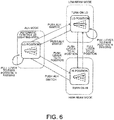
- FIG. 6 is a diagram illustrating irradiation control of the headlight 11 by the controller 100.
- the controller 100 controls the irradiation of the headlight 11 as shown in FIG. 6 according to the position of the lever switch 41 and the position of the ALH switch 43.
- the controller 100 sets the irradiation mode to the high beam mode.
- the controller 100 changes the irradiation mode to the low beam mode.
- the controller 100 changes the irradiation mode to the ALH mode.
- the controller 100 changes the irradiation mode to the low beam mode.
- the controller 100 changes the irradiation mode to the ALH mode and also moves the lever switch 41 to the Lo position.
- the controller 100 changes the irradiation mode to the high beam mode.
- the controller 100 When the lever switch 41 is in the low position and the irradiation mode is set to the low beam mode or the ALH mode, if the operation to pull the lever switch 41 to the Pass position is performed, the controller 100 performs a passing irradiation. Since the lever switch 41 is energized to the Lo position side, when the user's hand is released, it automatically returns to the Lo position.
- the push-in operation to the ALH switch 43 is performed once while the current irradiation mode is in the low beam or high beam mode, it is switched to the ALH mode. According to this, even when the current irradiation mode is in either the low beam mode or the high beam mode, it can be switched to the ALH mode only by performing the push-in operation to the ALH switch 43 once. Therefore, the convenience for the user of the vehicle 1 having the ALH mode can be improved. In particular, when the ALH mode is set, since the lever switch 41 is always located at the Lo position, the user can easily recognize that the mode is set to the ALH mode. Therefore, also on this point, the convenience for the user can be improved.
- the irradiation mode is changed to the high beam mode. Therefore, the change from the ALH mode to the high beam mode can be performed intuitively by a single operation.
- the change from the high beam mode to the low beam mode can be performed by a single operation to the lever switch 41 similar to a conventional case.
- the Lo position of the ALH mode can be used as a standard position.
- the switching control of the irradiation mode described in FIG. 6 is performed.
- the switching control of the irradiation mode can be also performed similar to that described in FIG. 6 .
- the switching device for the vehicle headlight of the present embodiment described above has the following configurations and features.
- the switching device for a vehicle headlight of the present embodiment having a low beam mode for irradiating a short distance area of a vehicle 1, a high beam mode for irradiating a long distance area of the vehicle 1, an ALH mode for irradiating an area set based on a detection result of a predetermined detection device, as irradiating modes for a headlight 11, comprises a lever switch 41 movably supported in a Lo position (an initial position) and a Hi position (a predetermined moved position), an ALH switch 43 for accepting a push-in operation (a switching operation) of setting of the ALH mode, and a controller 100 for changing an irradiation mode of the headlight 11 according to an operation (moving operation input) of the lever switch 41 and an operation (switching operation input) of the ALH switch 43.
- the controller 100 changes the irradiation mode to the ALH mode.
- the lever switch 41 is in the Lo position (the initial position) and the irradiation mode is set to the ALH mode
- the controller 100 changes the irradiation mode to the low beam mode.
- the lever switch 41 is in the Hi position (the predetermined moved position)
- the controller 100 sets the high beam mode.
- the controller 100 changes the irradiation mode to the ALH mode and also moves the lever switch 41 to the Lo position (the initial position).
- the controller 100 changes the irradiation mode to the high beam mode.
- the change from the ALH mode to the high beam mode can be operated intuitively.
- the controller 100 changes the irradiation mode to the low beam mode.
- the change from the high beam mode to the low beam mode can be operated intuitively.
- the switching device of the vehicle headlight of the present invention can be widely used for a vehicle having a vehicle headlight.
Landscapes
- Engineering & Computer Science (AREA)
- Mechanical Engineering (AREA)
- Physics & Mathematics (AREA)
- Microelectronics & Electronic Packaging (AREA)
- Optics & Photonics (AREA)
- General Engineering & Computer Science (AREA)
- Lighting Device Outwards From Vehicle And Optical Signal (AREA)
- Switches With Compound Operations (AREA)
Description
- The present invention relates to a switching device for a headlight provided on a vehicle, a headlight system for a vehicle, a vehicle, a method of switching modes of a vehicle headlight, and a computer program product.
- Non-Patent
Document 1 discloses a vehicle with light emitting diode (LED) headlights, which has an adaptive mode, or Adaptive LED Headlight (ALH) mode for controlling an irradiation area of a headlight based on a detection result of a forward sensing camera. - Mazda Roadster Instruction Manual 1st edition (November 2017 Published by Mazda Co., Ltd., Page. 202)
-
DE 10 2013 021 874 A1 discloses a switching device for a vehicle headlight comprising a rotary switch enabling the selection of the modes Off, position light and forward lighting (high/low beam) and a pushbutton to activate or deactivate an automatic mode. - For a conventional vehicle, in order to switch from a low beam mode to an ALH mode, it is necessary to switch a lamp switch to an AUTO position and further to move a lever switch, that is, a steering column lever switch mounted to a steering column of a vehicle, from a low beam position to a high beam position.
- An object of the present invention is improving a user's convenience on a vehicle having an ALH mode.
- The present invention is a switching device for a vehicle headlight according to
claim 1, having a low beam mode , a high beam mode, and an adaptive mode for irradiating an area that is set based on a detection result of a detection device as irradiating modes for the vehicle headlight. The switching device includes a steering column lever switch supported on a steering column of a vehicle so as to be movable between stationary initial position and a predetermined stationary moved position by a moving operation input, an ALH switch configured to receive a switching operation input to set the adaptive mode, and a controller configured to change the irradiation mode of the headlight according to a position of the lever switch and the switching operation input received by the ALH switch. The controller is configured to change the irradiation mode, when the lever switch is in the initial position and the irradiation mode is set to the low beam mode, and the switching operation input on the ALH switch is received, to the adaptive mode. The controller is configured to change the irradiation mode, when the lever switch is in the initial position and the irradiation mode is set to the adaptive mode, and the switching operation input on the ALH switch is received, to the low beam mode. The controller is configured to set the irradiation mode, when the lever switch is in the predetermined moved position, to the high beam mode. The controller is configured to change the irradiation mode, when the switch is in the predetermined moved position and the irradiation mode is set to the high beam mode, and the switching operation input on the ALH switch is received, to the adaptive mode. The controller is configured to move the lever switch, when the switch is in the predetermined moved position and the irradiation mode is set to the high beam mode, and the switching operation input on the ALH switch is received, to the initial position. - Particularly, the low beam mode is a mode for irradiating a short distance area of the vehicle.
- Further particularly, the high beam mode is a mode for irradiating a long distance area of the vehicle.
- Further particularly, the low beam mode is a mode for irradiating a first distance area of a vehicle. The high beam mode is a mode for irradiating a second distance area of the vehicle. The first distance area is shorter than the second distance area.
- Further particularly, the controller is configured to change the irradiation mode, when the lever switch is in the initial position and the irradiation mode is set to the adaptive mode, and the moving operation input is performed on the lever switch to move the lever switch to the predetermined moved position, to the high beam mode.
- Further particularly, the controller is configured to change the irradiation mode, when the lever switch is in the predetermined moved position and the irradiation mode is set to the high beam mode, and the moving operation input is performed on the lever switch to move the lever switch to the initial position, the controller changes the irradiation mode to the low beam mode.
- Further particularly, the controller is configured to control the vehicle headlight to change an area irradiated by the vehicle headlight in the adaptive mode.
- Further particularly, a headlight system for a vehicle includes a headlight and the above switching device. The headlight has a low beam mode, a high beam mode, and an adaptive mode for irradiating an area that is set based on a detection result of a detection device as irradiating modes for the headlight.
- Further particularly, the low beam mode is a mode for irradiating a first distance area of a vehicle. The high beam mode is a mode for irradiating a second distance area of the vehicle. The first distance area is shorter than the second distance area.
- Further particularly, a vehicle includes the above headlight system.
- Further particularly, the present invention is a method of switching modes of a vehicle headlight as defined in
claim 11. The vehicle headlight has a low beam mode, a high beam mode, and an adaptive mode for irradiating an area that is set based on a detection result of a detection device as irradiating modes for the vehicle headlight. The vehicle headlight is configured to be controlled by the above switching device. The method includes changing the irradiation mode of the headlight according to a position of the lever switch and the switching operation input received by the ALH switch, changing the irradiation mode to the adaptive mode, when the lever switch is in the initial position and the irradiation mode is set to the low beam mode, and the switching operation input on the ALH switch is received, changing the irradiation mode, when the lever switch is in the initial position and the irradiation mode is set to the adaptive mode, and the switching operation input on the ALH switch is received, to the low beam mode, setting the irradiation mode, when the lever switch is in the predetermined moved position, to the high beam mode, changing the irradiation mode, when the switch is in the predetermined moved position and the irradiation mode is set to the high beam mode, and the switching operation input on the ALH switch is received, to the adaptive mode, and moving the lever switch, when the switch is in the predetermined moved position and the irradiation mode is set to the high beam mode, and the switching operation input on the ALH switch is received, to the initial position. - Further particularly, the low beam mode is a mode for irradiating a first distance area of a vehicle. The high beam mode is a mode for irradiating a second distance area of the vehicle. The first distance area is shorter than the second distance area.
- Further particularly, a computer program product includes computer-readable instructions which, when loaded and executed on a suitable system, perform the above method.
- The present invention, according to a first aspect, is particularly a switching device for a vehicle headlight having a low beam mode for irradiating a short distance area of the vehicle, a high beam mode for irradiating a long distance area of the vehicle, and an ALH mode for irradiating an area that is set based on a detection result of a predetermined detection device as irradiating modes for the headlight. The switching device may include a steering column lever switch supported on a steering column of the vehicle so as to be movable between an initial position and a predetermined moved position by a moving operation input, an ALH switch configured to receive a switching operation input that sets the ALH mode, and a controller configured to change the irradiation mode of the headlight according to a position of the lever switch and the switching operation input received by the ALH switch. When the lever switch is in the initial position and the irradiation mode is set to the low beam mode, and the switching operation input on the ALH switch is received, the controller changes the irradiation mode to the ALH mode. When the lever switch is in the initial position and the irradiation mode is set to the ALH mode, and the switching operation input on the ALH switch is received, the controller changes the irradiation mode to the low beam mode. When the lever switch is in the predetermined moved position, the controller sets the irradiation mode to the high beam mode. Further, when the lever switch is in the predetermined moved position and the irradiation mode is set to the high beam mode, and the switching operation input on the ALH switch is received, the controller changes the irradiation mode to the ALH mode and also moves the lever switch to the initial position.
- According particularly to a second aspect, when the lever switch is in the initial position and the irradiation mode is set to the ALH mode, and the moving operation input is performed on the lever switch to move the lever to a predetermined moved position, the controller changes the irradiation mode to the high beam mode.
- According particularly to a third aspect, when the lever switch is in the predetermined moved position and the irradiation mode is set to the high beam mode, and the moving operation input is received on the lever switch to move the lever switch to the initial position, the controller changes the irradiation mode to the low beam mode.
- According to the first aspect above, even when the current irradiation mode is in either the low beam or the high beam mode, the mode can be switched to the ALH mode only by performing a single switching operation on the ALH switch. Therefore, the convenience of the user can be improved with the vehicle having the ALH mode. In particular, when the ALH mode is set, since the lever switch is always located at the initial position, the user can easily recognize that the mode is set to the ALH mode.
- According to the second aspect, the change from the ALH mode to the high beam mode can be operated intuitively.
- According to the third aspect, the change from the high beam mode to the low beam mode can be operated intuitively.
-
-
FIG. 1 is an outline drawing of a vehicle having a switching device for a vehicle headlight according to a first embodiment of the present invention. -
FIG. 2 is a drawing schematically showing an appearance of a steering wheel part. -
FIG. 3 is an outline drawing of a steering column lever switch. -
FIG. 4 is a diagram illustrating movements of a steering column lever switch. -
FIG. 5 is a diagram showing a control system. -
FIG. 6 is a diagram illustrating irradiation controls of a headlight by a controller. - Hereinafter, a switching device for a vehicle headlight according to an embodiment of the present invention will be described.
-
FIG. 1 is an outline drawing of a vehicle having a switching device for a vehicle headlight according to a first embodiment of the present invention. - A
vehicle 1 is particularly a vehicle having four wheels driven by an engine and a transmission, and aheadlight 11 and a parking light (also referred to as a "sidelight") 12 are provided on the left and right of a front part of thevehicle 1. -
Headlight 11 particularly includes an LED (Light Emitting Diode) light divided into a plurality of blocks each having an LED positioned therein. The LED can be turned on/off for each block. - The
vehicle 1 includes, as irradiation modes of theheadlight 11, a low beam mode for irradiating a short distance area of thevehicle 1 with a low beam, a high beam mode for irradiating a long distance area of thevehicle 1 with a high beam, and an ALH (Adaptive LED Headlight) mode for generating and irradiating a beam corresponding to the area set based on a detection result of aforward sensing camera 20. In the ALH mode, the distribution of light emitted by the headlights is changed, for example in pattern and intensity, by controllably varying the pattern and intensity of the individual LEDs which are lighted up, based upon the travelling conditions in the environment surrounding, and particularly forward of, the vehicle. ALH mode is sometimes referred to as adaptive high beam control, adaptive driving headlights, etc. in other contexts. - As used herein the term "short distance area" refers to an area, as viewed from above, on the plane on which the vehicle is positioned that is illuminated by the headlights in the low beam mode, while "long distance area" refers to an area, as viewed from above, on the plane on which the vehicle is positioned that is illuminated by the headlights in the high beam mode. The short distance of the short distance mode and long distance of the long distance mode are measured from a front of the vehicle itself to a furthest point of each respective the illuminated area in front of the vehicle in each mode. It will be appreciated that the short distance is shorter than the long distance, since the headlights in the high beam mode project further than in the low beam mode. Switching of the irradiation mode of the
headlight 11 is controlled by acontroller 100 according to a user's operation with respect to various switches and the like which will be described later. It will be appreciated thatcontroller 100 typically includes a microprocessor with associated nonvolatile memory that store programs configured to execute the functions described herein using portions of volatile memory. The microprocessor may be an application specific integrated circuit (ASIC), a central processing unit (CPU), or other suitable form of processor. - The
forward sensing camera 20 is an example of a predetermined detection device and is provided on an upper indoor side of a windshield. Theforward sensing camera 20 captures a moving image and outputs it to thecontroller 100. - In the ALH mode, the irradiation area of the
headlight 11 is automatically changed based on the detection result of theforward sensing camera 20. For example, based on the detection result of theforward sensing camera 20, a short distance area of thevehicle 1 is irradiated similarly to the low beam mode, a long distance area of thevehicle 1 is irradiated similarly to the high beam mode, illumination is reduced to a part of the long distance area when high beams are on, or the irradiation area when low beams are on is enlarged in the vehicle width direction. The irradiation area of theheadlight 11 can be controlled, for example, by controlling the turning on and/or off the LEDs of theheadlight 11 for each block. -
FIG. 2 is a drawing schematically showing an appearance of a steering wheel part. - A steering column lever switch 41 (also referred herein as "lever switch") is particularly arranged in front of a
steering wheel 30 provided in the passenger compartment. The steeringcolumn lever switch 41 may be provided on either right or left side of the steering column. -
FIG. 3 is an outline drawing of thelever switch 41. - The
lever switch 41 has a lever shape and is particularly supported by a supportingpart 41a provided on abase 31 of a steering device at one end. Thelever switch 41 is supported on the steering column of the vehicle so as to be movable between an initial position and a predetermined moved position by a moving operation input, such as movement by the hand of a user, as described below. -
FIG. 4 is a diagram illustrating movements of thelever switch 41. - The
lever switch 41 is particularly supported by the supportingpart 41a so as to be movable (for example, in a swingable fashion) in a longitudinal direction of the vehicle about the one end side. It will be noted that thelever switch 41 is movable into and out of the page inFIG. 3 , which corresponds to towards the top and bottom of the page inFIG. 4 , as shown. Specifically, the supportingpart 41a particularly supports thelever switch 41 movably between a Hi position and a Pass position across a Lo position. The Lo position is an example of an initial position, and the Hi position is an example of a predetermined moved position. When thelever switch 41 is moved to the Lo position by a user operation, the supportingpart 41a holds thelever switch 41 at the Lo position. Moreover, when thelever switch 41 is moved to the Hi position by the user operation, the supportingpart 41a holds thelever switch 41 at the Hi position. Further, when thelever switch 41 is moved to the Pass position by the user operation, the supportingpart 41a moves thelever switch 41 to the Lo position without holding it at the Pass position. That is, the movement of thelever switch 41 between the Hi position and the Lo position is stationary and the movement from the Lo position to the Pass position is momentary. The supportingpart 41a may perform the above described hold by only a mechanical part (i.e., a mechanism) or may perform the above described hold by the mechanical part and an electric part such as a motor (i.e., an electromechanical system). - When the
lever switch 41 is in the Hi position, the Lo position, or the Pass position, the supportingpart 41a particularly performs not only the supporting function but also forms a circuit corresponding to each. According to this, thecontroller 100 can detect the current position of thelever switch 41. - Returning to
FIG. 3 , alamp switch 42 is particularly provided on a tip end side of thelever switch 41. Thelamp switch 42 is particularly rotatable about the longitudinal direction of the lever, and a triangular selection mark M1 is provided thereon. When thelamp switch 42 is rotated to set the selection mark M1 to an OFF mark M2, an AUTO mark M3, a parking light mark M4, and a head lamp mark M5, a circuit corresponding to each is particularly formed. According to this, thecontroller 100 can detect the current position of thelamp switch 42. Moreover, hereinafter, when the selection mark M1 of thelamp switch 42 is set to the OFF mark M2, the AUTO mark M3, the parking light mark M4, or the head lamp mark M5, it indicates that thelamp switch 42 is in the OFF position, the AUTO position, the parking light position, or the head lamp position. - An
ALH switch 43 is particularly provided on the tip end surface of thelever switch 41. TheALH switch 43 may be a push button type switch that can be pushed-in along a longitudinal axis direction of the lever (i.e., toward the steering column). TheALH switch 43 is particularly energized in a direction projecting from the tip end surface in the long axis direction of the lever. According to this, after theALH switch 43 is pushed with a finger at a reference position shown inFIG. 3 , when the finger is released, it returns to the reference position. While theALH switch 43 is pushed in, an ON circuit is formed. According to this, thecontroller 100 can detect that a push-in operation was performed to theALH switch 43. -
FIG. 5 is a diagram showing a control system. - As discussed above,
vehicle 1 particularly includes thecontroller 100 that controls an irradiation state of theheadlight 11. Thelever switch 41, thelamp switch 42, theALH switch 43, theforward sensing camera 20, theheadlight 11, and theparking light 12 are electrically connected to thecontroller 100. Thecontroller 100 particularly detects the positions of thelever switch 41, thelamp switch 42, and theALH switch 43 and also receives as inputs the moving images captured by theforward sensing camera 20. Then, thecontroller 100 particularly controls the irradiation of theheadlight 11 based on the detected positions of the respective switches and the moving images captured by theforward sensing camera 20. The irradiation states of theheadlight 11 and theparking light 12 are different depending on whether the power switch of thevehicle 1 is in the ON position, the OFF position, or the ACC position, however it is assumed that the power switch is in the ON position in the following description. - Specifically, when the
lamp switch 42 is in the OFF position, thecontroller 100 turns on neither theheadlight 11 or theparking light 12. - When the
lamp switch 42 is in the AUTO position, thecontroller 100 automatically turns on/off theheadlight 11 and theparking light 12 according to the illuminance detected by an illuminance sensor (not shown). Moreover, when it is in the AUTO position, the ON/OFF state of the ALH function is controlled according to the position of thelever switch 41 and the position of theALH switch 43. - The
controller 100 particularly turns on theparking light 12 when thelamp switch 42 is in the parking light position. - When the
lamp switch 42 is in the headlight position, thecontroller 100 particularly turns on theheadlight 11 and theparking light 12. -
FIG. 6 is a diagram illustrating irradiation control of theheadlight 11 by thecontroller 100. - When the
lamp switch 42 is in the AUTO position, thecontroller 100 controls the irradiation of theheadlight 11 as shown inFIG. 6 according to the position of thelever switch 41 and the position of theALH switch 43. - That is, when the
lever switch 41 is in the Lo position and the irradiation mode is set to the low beam mode, if the operation to push thelever switch 41 to the Hi position is performed, thecontroller 100 sets the irradiation mode to the high beam mode. - When the
lever switch 41 is in the Hi position and the irradiation mode is set to the high beam mode, if the operation to pull thelever switch 41 to the Lo position is performed, thecontroller 100 changes the irradiation mode to the low beam mode. - When the
lever switch 41 is in the Lo position and the irradiation mode is set to the low beam mode, if the push-in operation to theALH switch 43 is performed, thecontroller 100 changes the irradiation mode to the ALH mode. - When the
lever switch 41 is in the Lo position and the irradiation mode is set to the ALH mode, if the push-in operation to theALH switch 43 is performed, thecontroller 100 changes the irradiation mode to the low beam mode. - When the
lever switch 41 is in the Hi position and the irradiation mode is set to the high beam mode, if the push-in operation to theALH switch 43 is performed, thecontroller 100 changes the irradiation mode to the ALH mode and also moves thelever switch 41 to the Lo position. - When the
lever switch 41 is in the Lo position and the irradiation mode is set to the ALH mode, if the operation to push thelever switch 41 to the Hi position is performed, thecontroller 100 changes the irradiation mode to the high beam mode. - When the
lever switch 41 is in the low position and the irradiation mode is set to the low beam mode or the ALH mode, if the operation to pull thelever switch 41 to the Pass position is performed, thecontroller 100 performs a passing irradiation. Since thelever switch 41 is energized to the Lo position side, when the user's hand is released, it automatically returns to the Lo position. - According to the present embodiment, if the push-in operation to the
ALH switch 43 is performed once while the current irradiation mode is in the low beam or high beam mode, it is switched to the ALH mode. According to this, even when the current irradiation mode is in either the low beam mode or the high beam mode, it can be switched to the ALH mode only by performing the push-in operation to theALH switch 43 once. Therefore, the convenience for the user of thevehicle 1 having the ALH mode can be improved. In particular, when the ALH mode is set, since thelever switch 41 is always located at the Lo position, the user can easily recognize that the mode is set to the ALH mode. Therefore, also on this point, the convenience for the user can be improved. - Moreover, according to the present embodiment, when the operation to push the
lever switch 41 to the Hi position is performed while the irradiation mode is set to the ALH mode, the irradiation mode is changed to the high beam mode. Therefore, the change from the ALH mode to the high beam mode can be performed intuitively by a single operation. - Further, the change from the high beam mode to the low beam mode can be performed by a single operation to the
lever switch 41 similar to a conventional case. - Moreover, by adopting the above described configuration, as is clearly shown in
FIG. 6 , since it is possible to change from the ALH mode to the low beam mode or to the high beam mode by a single operation respectively, the Lo position of the ALH mode can be used as a standard position. - In the
embodiment 1, when thelamp switch 42 is in the AUTO position, the switching control of the irradiation mode described inFIG. 6 is performed. However, even when thelamp switch 42 is in the headlight position, the switching control of the irradiation mode can be also performed similar to that described inFIG. 6 . - The switching device for the vehicle headlight of the present embodiment described above has the following configurations and features.
- Therefore, the switching device for a vehicle headlight of the present embodiment having a low beam mode for irradiating a short distance area of a
vehicle 1, a high beam mode for irradiating a long distance area of thevehicle 1, an ALH mode for irradiating an area set based on a detection result of a predetermined detection device, as irradiating modes for aheadlight 11, comprises alever switch 41 movably supported in a Lo position (an initial position) and a Hi position (a predetermined moved position), anALH switch 43 for accepting a push-in operation (a switching operation) of setting of the ALH mode, and acontroller 100 for changing an irradiation mode of theheadlight 11 according to an operation (moving operation input) of thelever switch 41 and an operation (switching operation input) of theALH switch 43. - When the
lever switch 41 is in the Lo position (the initial position) and the irradiation mode is set to the low beam mode, if the push-in operation (the switching operation) to theALH switch 43 is performed, thecontroller 100 changes the irradiation mode to the ALH mode. When thelever switch 41 is in the Lo position (the initial position) and the irradiation mode is set to the ALH mode, if the push-in operation (the switching operation) to theALH switch 43 is performed, thecontroller 100 changes the irradiation mode to the low beam mode. When thelever switch 41 is in the Hi position (the predetermined moved position), thecontroller 100 sets the high beam mode. Further, when thelever switch 41 is in the Hi position (the predetermined moved position) and the irradiation mode is set to the high beam mode, if the push-in operation (the switching operation input) to theALH switch 43 is performed, thecontroller 100 changes the irradiation mode to the ALH mode and also moves thelever switch 41 to the Lo position (the initial position). - According to this configuration, convenience for the user of the
vehicle 1 having the ALH mode can be improved. - Moreover, on the switching device for the vehicle headlight according to the present embodiment, when the
lever switch 41 is in the Lo position (the initial position) and the irradiation mode is set to the ALH mode, if the operation to push thelever switch 41 to the Hi position (the moving operation to the predetermined moving position) is performed, thecontroller 100 changes the irradiation mode to the high beam mode. - According to this, the change from the ALH mode to the high beam mode can be operated intuitively.
- Moreover, on the switching device for the vehicle headlight according to the present embodiment, when the
lever switch 41 is in the Hi position (the predetermined moving position) and the irradiation mode is set to the high beam mode, if the operation to pull thelever switch 41 to the Lo position (the moving operation to the initial position) performed, thecontroller 100 changes the irradiation mode to the low beam mode. - According to this, the change from the high beam mode to the low beam mode can be operated intuitively.
- The switching device of the vehicle headlight of the present invention can be widely used for a vehicle having a vehicle headlight.
- It should be understood that the embodiments herein are illustrative and not restrictive, since the scope of the invention is defined by the appended claims.
-
- 1
- Vehicle
- 11
- Headlight
- 12
- Parking light (sidelight)
- 20
- Forward sensing camera
- 30
- Steering wheels
- 31
- Base
- 41
- Lever switch
- 42
- Lamp switch
- 43
- ALH switch
- 100
- Controller
Claims (13)
- A switching device for a vehicle headlight (11) having a low beam mode, a high beam mode, and an adaptive mode for irradiating an area that is set based on a detection result of a detection device as irradiating modes for the vehicle headlight (11), the switching device comprising:a steering column lever switch (41) supported on a steering column of a vehicle (1) so as to be movable by a moving operation input between a stationary initial position and a predetermined stationary moved position,a switch (43) configured to receive a switching operation input to set the adaptive mode, anda controller (100) configured to change the irradiation mode of the headlight (11) according to a position of the lever switch (41) and the switching operation input received by the switch (43),wherein the controller (100) is configured to change the irradiation mode to the adaptive mode, when the lever switch (41) is in the initial position and the irradiation mode is set to the low beam mode, and the switching operation input on the switch (43) is received,wherein the controller (100) is configured to change the irradiation mode to the low beam mode, when the lever switch (41) is in the initial position and the irradiation mode is set to the adaptive mode, and the switching operation input on the switch (43) is received,wherein the controller (100) is configured to set the irradiation mode to the high beam mode, when the lever switch (41) is in the predetermined moved position,wherein the controller (100) is configured to change the irradiation mode to the adaptive mode and to move the lever switch (41) to the initial position, when the lever switch (41) is in the predetermined moved position and the irradiation mode is set to the high beam mode, and the switching operation input on the switch (43) is received.
- The switching device for the vehicle headlight (11) according claim 1, wherein the low beam mode is a mode for irradiating a short distance area of a vehicle (1).
- The switching device for the vehicle headlight (11) according claim 1 or 2, wherein the high beam mode is a mode for irradiating a long distance area of the vehicle (1).
- The switching device for the vehicle headlight (11) according any one of the preceding claims, wherein
the low beam mode is a mode for irradiating a first distance area of a vehicle (1),
the high beam mode is a mode for irradiating a second distance area of the vehicle (1), and
the first distance area is shorter than the second distance area. - The switching device for the vehicle headlight (11) according to any one of the preceding claims,
wherein the controller (100) is configured to change the irradiation mode to the high beam mode, when the lever switch (41) is in the initial position and the irradiation mode is set to the adaptive mode, and the moving operation input is performed on the lever switch (41) to move the lever switch (41) to the predetermined moved position. - The switching device for the vehicle headlight (11) according to any one of the preceding claims,
wherein the controller (100) is configured to change the irradiation mode to the low beam mode, when the lever switch (41) is in the predetermined moved position and the irradiation mode is set to the high beam mode, and the moving operation input is performed on the lever switch (41) to move the lever switch (41) to the initial position. - The switching device for the vehicle headlight (11) according to any one of the preceding claims, wherein the controller (100) is configured to control the vehicle headlight (11) to change an area irradiated by the vehicle headlight (11) in the adaptive mode.
- A headlight system for a vehicle (1), comprising:a headlight (11) having a low beam mode, a high beam mode, and an adaptive mode for irradiating an area that is set based on a detection result of a detection device as irradiating modes for the headlight (11); andthe switching device according to any one of the preceding claims.
- The headlight system according to claim 8, wherein
the low beam mode is a mode for irradiating a first distance area of a vehicle (1),
the high beam mode is a mode for irradiating a second distance area of the vehicle (1), and
the first distance area is shorter than the second distance area. - A vehicle (1) comprising the headlight system according to claim 8 or 9.
- A method of switching modes of a vehicle headlight (11) having a low beam mode, a high beam mode, and an adaptive mode for irradiating an area that is set based on a detection result of a detection device as irradiating modes for the vehicle headlight (11), wherein the vehicle headlight (1) is configured to be controlled by a switching device according to any one of claims 1 to 7, the method comprising:changing the irradiation mode of the headlight (11) according to a position of the lever switch (41) and the switching operation input received by the switch (43);changing the irradiation mode to the adaptive mode, when the lever switch (41) is in the initial position and the irradiation mode is set to the low beam mode, and the switching operation input on the switch (43) is received;changing the irradiation mode to the low beam mode, when the lever switch (41) is in the initial position and the irradiation mode is set to the adaptive mode, and the switching operation input on the switch (43) is received;setting the irradiation mode, when the lever switch (41) is in the predetermined moved position, to the high beam mode;changing the irradiation mode to the adaptive mode and moving the lever switch (41) to the initial position, when the switch (41) is in the predetermined moved position and the irradiation mode is set to the high beam mode, and the switching operation input on the switch (43) is received.
- The method according to claim 11, wherein
the low beam mode is a mode for irradiating a first distance area of a vehicle (1),
the high beam mode is a mode for irradiating a second distance area of the vehicle (1), and
the first distance area is shorter than the second distance area. - A computer program product comprising computer-readable instructions which, when loaded and executed on a suitable system, perform a method according to claim 11 or 12.
Applications Claiming Priority (1)
| Application Number | Priority Date | Filing Date | Title |
|---|---|---|---|
| JP2018055099A JP7110650B2 (en) | 2018-03-22 | 2018-03-22 | Vehicle headlight switch device |
Publications (2)
| Publication Number | Publication Date |
|---|---|
| EP3546289A1 EP3546289A1 (en) | 2019-10-02 |
| EP3546289B1 true EP3546289B1 (en) | 2020-10-21 |
Family
ID=65894853
Family Applications (1)
| Application Number | Title | Priority Date | Filing Date |
|---|---|---|---|
| EP19163421.1A Active EP3546289B1 (en) | 2018-03-22 | 2019-03-18 | Switching device for vehicle headlight, headlight system, vehicle, method of switching modes of vehicle headlight, and computer program product |
Country Status (4)
| Country | Link |
|---|---|
| US (1) | US10464471B2 (en) |
| EP (1) | EP3546289B1 (en) |
| JP (1) | JP7110650B2 (en) |
| CN (1) | CN110293899B (en) |
Families Citing this family (4)
| Publication number | Priority date | Publication date | Assignee | Title |
|---|---|---|---|---|
| JP7585000B2 (en) * | 2020-11-16 | 2024-11-18 | カワサキモータース株式会社 | Saddle-type vehicle and light control method thereof |
| JP7655067B2 (en) | 2021-04-23 | 2025-04-02 | 市光工業株式会社 | Vehicle lighting fixtures |
| JP7697285B2 (en) | 2021-06-18 | 2025-06-24 | スズキ株式会社 | Vehicle headlamp mode selection device |
| KR20240036381A (en) * | 2022-09-13 | 2024-03-20 | 현대자동차주식회사 | Auto leveling system and method for headlamp |
Family Cites Families (26)
| Publication number | Priority date | Publication date | Assignee | Title |
|---|---|---|---|---|
| JPH05278518A (en) * | 1992-03-31 | 1993-10-26 | Mazda Motor Corp | Vehicle headlight lighting control device |
| US5977494A (en) * | 1995-09-08 | 1999-11-02 | Yazaki Corporation | Symmetrically mounted switches on steering wheel column body including wiring connection and control unit |
| US7653215B2 (en) * | 1997-04-02 | 2010-01-26 | Gentex Corporation | System for controlling exterior vehicle lights |
| US6861809B2 (en) * | 1998-09-18 | 2005-03-01 | Gentex Corporation | Headlamp control to prevent glare |
| US8120652B2 (en) * | 1997-04-02 | 2012-02-21 | Gentex Corporation | System for controlling vehicle equipment |
| US6049171A (en) * | 1998-09-18 | 2000-04-11 | Gentex Corporation | Continuously variable headlamp control |
| DE10037760A1 (en) * | 2000-08-03 | 2002-02-14 | Eaton Corp | Reset device for a switch of a motor vehicle |
| JP3753932B2 (en) * | 2000-08-09 | 2006-03-08 | 株式会社小糸製作所 | Vehicle headlight system |
| US6774323B2 (en) * | 2002-09-23 | 2004-08-10 | Lear Corporation | Multi-function rotary vehicle switch mounted to a fixed stalk |
| US7541743B2 (en) * | 2002-12-13 | 2009-06-02 | Ford Global Technologies, Llc | Adaptive vehicle communication controlled lighting system |
| US8045760B2 (en) * | 2003-02-21 | 2011-10-25 | Gentex Corporation | Automatic vehicle exterior light control systems |
| DE10331776B3 (en) * | 2003-07-11 | 2005-05-04 | Siemens Ag | operating device |
| DE102006022022A1 (en) * | 2006-03-03 | 2007-09-06 | Daimlerchrysler Ag | Method and device for controlling the light functions in headlamps for road vehicles |
| JP2008114655A (en) * | 2006-11-01 | 2008-05-22 | Denso Corp | Vehicle lighting control device |
| DE102007017028A1 (en) * | 2007-04-11 | 2008-10-16 | Daimler Ag | Method and device for operating the lighting device of a road vehicle |
| DE102007035289A1 (en) * | 2007-07-27 | 2009-01-29 | Audi Ag | Motor vehicle comprises illumination device with manual switching of full beam and low beam, where assistance system is provided for automatic change between full beam and low beam |
| JP2009255639A (en) * | 2008-04-14 | 2009-11-05 | Denso Corp | Automatic lighting device for vehicle |
| CN103201137B (en) * | 2010-11-24 | 2015-09-09 | 丰田自动车株式会社 | The control method of Vehicular illumination device and headlight for automobile |
| JP5454526B2 (en) * | 2011-07-25 | 2014-03-26 | トヨタ自動車株式会社 | Vehicle light distribution control device and method |
| JP2013047058A (en) * | 2011-08-29 | 2013-03-07 | Denso Corp | Vehicle headlight control device |
| CN104583012B (en) * | 2012-08-02 | 2018-01-05 | 金泰克斯公司 | System and method for controlling exterior vehicle lights in response to detection of a pickup truck |
| JP2015009570A (en) * | 2013-06-26 | 2015-01-19 | 富士重工業株式会社 | Headlight control device |
| JP6191330B2 (en) * | 2013-08-20 | 2017-09-06 | 日産自動車株式会社 | Vehicle lighting control device |
| DE102013021874B4 (en) * | 2013-12-21 | 2019-10-10 | Audi Ag | Light control unit for a motor vehicle and motor vehicle |
| CN105202444A (en) * | 2014-06-26 | 2015-12-30 | 中强光电股份有限公司 | Lighting device for vehicle |
| US10317034B2 (en) * | 2017-10-26 | 2019-06-11 | Osram Sylvania Inc. | Integrated automotive adaptive driving beam headlamp and calibration method |
-
2018
- 2018-03-22 JP JP2018055099A patent/JP7110650B2/en active Active
-
2019
- 2019-03-07 CN CN201910172377.8A patent/CN110293899B/en active Active
- 2019-03-18 EP EP19163421.1A patent/EP3546289B1/en active Active
- 2019-03-22 US US16/361,539 patent/US10464471B2/en active Active
Non-Patent Citations (1)
| Title |
|---|
| None * |
Also Published As
| Publication number | Publication date |
|---|---|
| CN110293899B (en) | 2022-11-15 |
| JP2019166925A (en) | 2019-10-03 |
| US10464471B2 (en) | 2019-11-05 |
| EP3546289A1 (en) | 2019-10-02 |
| US20190291633A1 (en) | 2019-09-26 |
| JP7110650B2 (en) | 2022-08-02 |
| CN110293899A (en) | 2019-10-01 |
Similar Documents
| Publication | Publication Date | Title |
|---|---|---|
| EP3546289B1 (en) | Switching device for vehicle headlight, headlight system, vehicle, method of switching modes of vehicle headlight, and computer program product | |
| US7824085B2 (en) | Vehicular illumination device | |
| JP5233627B2 (en) | Vehicle lighting device | |
| US20080246404A1 (en) | Vehicle headlight beam controls | |
| US9815400B2 (en) | Headlight control device and headlight | |
| JP6350402B2 (en) | Vehicle headlamp control device | |
| US10821883B2 (en) | Headlamp control device for vehicle | |
| US20080192496A1 (en) | Lamp System For Vehicle | |
| EP2682306A2 (en) | Vehicle lamp system | |
| JP2008114655A (en) | Vehicle lighting control device | |
| JP2015209002A (en) | Illumination control system | |
| EP4001072B1 (en) | Straddle vehicle and light control method thereof | |
| JP2013109911A (en) | Lighting device | |
| JP2018020615A (en) | Parking support device | |
| WO2019194212A1 (en) | Vehicular light switch and vehicular light system | |
| JP2020026170A (en) | Vehicle lamp and lighting control method thereof | |
| JP2008114800A (en) | Vehicle lighting device | |
| KR102632934B1 (en) | Interior ramp apparatus of vehicle and control method thereof | |
| JP2009096249A (en) | Vehicle lighting device | |
| JP6409847B2 (en) | Vehicle headlight control device | |
| JP4735555B2 (en) | Vehicle lighting device | |
| KR20130068536A (en) | Lighting apparatus | |
| JP2014177186A (en) | Lighting control unit of vehicular headlamps and vehicular headlamp system | |
| JP6062774B2 (en) | Maneuvering support device | |
| KR20150072620A (en) | Lamp for vehicle |
Legal Events
| Date | Code | Title | Description |
|---|---|---|---|
| PUAI | Public reference made under article 153(3) epc to a published international application that has entered the european phase |
Free format text: ORIGINAL CODE: 0009012 |
|
| STAA | Information on the status of an ep patent application or granted ep patent |
Free format text: STATUS: THE APPLICATION HAS BEEN PUBLISHED |
|
| AK | Designated contracting states |
Kind code of ref document: A1 Designated state(s): AL AT BE BG CH CY CZ DE DK EE ES FI FR GB GR HR HU IE IS IT LI LT LU LV MC MK MT NL NO PL PT RO RS SE SI SK SM TR |
|
| AX | Request for extension of the european patent |
Extension state: BA ME |
|
| STAA | Information on the status of an ep patent application or granted ep patent |
Free format text: STATUS: REQUEST FOR EXAMINATION WAS MADE |
|
| 17P | Request for examination filed |
Effective date: 20200123 |
|
| RBV | Designated contracting states (corrected) |
Designated state(s): AL AT BE BG CH CY CZ DE DK EE ES FI FR GB GR HR HU IE IS IT LI LT LU LV MC MK MT NL NO PL PT RO RS SE SI SK SM TR |
|
| RIC1 | Information provided on ipc code assigned before grant |
Ipc: B60Q 1/14 20060101AFI20200212BHEP Ipc: B60Q 1/00 20060101ALI20200212BHEP |
|
| GRAP | Despatch of communication of intention to grant a patent |
Free format text: ORIGINAL CODE: EPIDOSNIGR1 |
|
| STAA | Information on the status of an ep patent application or granted ep patent |
Free format text: STATUS: GRANT OF PATENT IS INTENDED |
|
| INTG | Intention to grant announced |
Effective date: 20200331 |
|
| RIN1 | Information on inventor provided before grant (corrected) |
Inventor name: YAMAOKA, MANABU Inventor name: OHTSUBO, TOMONORI Inventor name: SUEISHI, KATSUYA Inventor name: SATO, KEIICHI Inventor name: YAMAMOTO, KEIICHIROU |
|
| GRAS | Grant fee paid |
Free format text: ORIGINAL CODE: EPIDOSNIGR3 |
|
| GRAJ | Information related to disapproval of communication of intention to grant by the applicant or resumption of examination proceedings by the epo deleted |
Free format text: ORIGINAL CODE: EPIDOSDIGR1 |
|
| GRAL | Information related to payment of fee for publishing/printing deleted |
Free format text: ORIGINAL CODE: EPIDOSDIGR3 |
|
| STAA | Information on the status of an ep patent application or granted ep patent |
Free format text: STATUS: REQUEST FOR EXAMINATION WAS MADE |
|
| INTC | Intention to grant announced (deleted) | ||
| GRAR | Information related to intention to grant a patent recorded |
Free format text: ORIGINAL CODE: EPIDOSNIGR71 |
|
| STAA | Information on the status of an ep patent application or granted ep patent |
Free format text: STATUS: GRANT OF PATENT IS INTENDED |
|
| GRAA | (expected) grant |
Free format text: ORIGINAL CODE: 0009210 |
|
| STAA | Information on the status of an ep patent application or granted ep patent |
Free format text: STATUS: THE PATENT HAS BEEN GRANTED |
|
| AK | Designated contracting states |
Kind code of ref document: B1 Designated state(s): AL AT BE BG CH CY CZ DE DK EE ES FI FR GB GR HR HU IE IS IT LI LT LU LV MC MK MT NL NO PL PT RO RS SE SI SK SM TR |
|
| INTG | Intention to grant announced |
Effective date: 20200914 |
|
| REG | Reference to a national code |
Ref country code: GB Ref legal event code: FG4D |
|
| REG | Reference to a national code |
Ref country code: CH Ref legal event code: EP |
|
| REG | Reference to a national code |
Ref country code: IE Ref legal event code: FG4D |
|
| REG | Reference to a national code |
Ref country code: AT Ref legal event code: REF Ref document number: 1325519 Country of ref document: AT Kind code of ref document: T Effective date: 20201115 |
|
| REG | Reference to a national code |
Ref country code: DE Ref legal event code: R096 Ref document number: 602019000996 Country of ref document: DE |
|
| REG | Reference to a national code |
Ref country code: AT Ref legal event code: MK05 Ref document number: 1325519 Country of ref document: AT Kind code of ref document: T Effective date: 20201021 |
|
| REG | Reference to a national code |
Ref country code: NL Ref legal event code: MP Effective date: 20201021 |
|
| PG25 | Lapsed in a contracting state [announced via postgrant information from national office to epo] |
Ref country code: PT Free format text: LAPSE BECAUSE OF FAILURE TO SUBMIT A TRANSLATION OF THE DESCRIPTION OR TO PAY THE FEE WITHIN THE PRESCRIBED TIME-LIMIT Effective date: 20210222 Ref country code: RS Free format text: LAPSE BECAUSE OF FAILURE TO SUBMIT A TRANSLATION OF THE DESCRIPTION OR TO PAY THE FEE WITHIN THE PRESCRIBED TIME-LIMIT Effective date: 20201021 Ref country code: FI Free format text: LAPSE BECAUSE OF FAILURE TO SUBMIT A TRANSLATION OF THE DESCRIPTION OR TO PAY THE FEE WITHIN THE PRESCRIBED TIME-LIMIT Effective date: 20201021 Ref country code: GR Free format text: LAPSE BECAUSE OF FAILURE TO SUBMIT A TRANSLATION OF THE DESCRIPTION OR TO PAY THE FEE WITHIN THE PRESCRIBED TIME-LIMIT Effective date: 20210122 Ref country code: NO Free format text: LAPSE BECAUSE OF FAILURE TO SUBMIT A TRANSLATION OF THE DESCRIPTION OR TO PAY THE FEE WITHIN THE PRESCRIBED TIME-LIMIT Effective date: 20210121 |
|
| REG | Reference to a national code |
Ref country code: LT Ref legal event code: MG4D |
|
| PG25 | Lapsed in a contracting state [announced via postgrant information from national office to epo] |
Ref country code: BG Free format text: LAPSE BECAUSE OF FAILURE TO SUBMIT A TRANSLATION OF THE DESCRIPTION OR TO PAY THE FEE WITHIN THE PRESCRIBED TIME-LIMIT Effective date: 20210121 Ref country code: PL Free format text: LAPSE BECAUSE OF FAILURE TO SUBMIT A TRANSLATION OF THE DESCRIPTION OR TO PAY THE FEE WITHIN THE PRESCRIBED TIME-LIMIT Effective date: 20201021 Ref country code: LV Free format text: LAPSE BECAUSE OF FAILURE TO SUBMIT A TRANSLATION OF THE DESCRIPTION OR TO PAY THE FEE WITHIN THE PRESCRIBED TIME-LIMIT Effective date: 20201021 Ref country code: IS Free format text: LAPSE BECAUSE OF FAILURE TO SUBMIT A TRANSLATION OF THE DESCRIPTION OR TO PAY THE FEE WITHIN THE PRESCRIBED TIME-LIMIT Effective date: 20210221 Ref country code: SE Free format text: LAPSE BECAUSE OF FAILURE TO SUBMIT A TRANSLATION OF THE DESCRIPTION OR TO PAY THE FEE WITHIN THE PRESCRIBED TIME-LIMIT Effective date: 20201021 Ref country code: ES Free format text: LAPSE BECAUSE OF FAILURE TO SUBMIT A TRANSLATION OF THE DESCRIPTION OR TO PAY THE FEE WITHIN THE PRESCRIBED TIME-LIMIT Effective date: 20201021 Ref country code: AT Free format text: LAPSE BECAUSE OF FAILURE TO SUBMIT A TRANSLATION OF THE DESCRIPTION OR TO PAY THE FEE WITHIN THE PRESCRIBED TIME-LIMIT Effective date: 20201021 |
|
| PG25 | Lapsed in a contracting state [announced via postgrant information from national office to epo] |
Ref country code: NL Free format text: LAPSE BECAUSE OF FAILURE TO SUBMIT A TRANSLATION OF THE DESCRIPTION OR TO PAY THE FEE WITHIN THE PRESCRIBED TIME-LIMIT Effective date: 20201021 Ref country code: HR Free format text: LAPSE BECAUSE OF FAILURE TO SUBMIT A TRANSLATION OF THE DESCRIPTION OR TO PAY THE FEE WITHIN THE PRESCRIBED TIME-LIMIT Effective date: 20201021 |
|
| REG | Reference to a national code |
Ref country code: DE Ref legal event code: R097 Ref document number: 602019000996 Country of ref document: DE |
|
| PG25 | Lapsed in a contracting state [announced via postgrant information from national office to epo] |
Ref country code: CZ Free format text: LAPSE BECAUSE OF FAILURE TO SUBMIT A TRANSLATION OF THE DESCRIPTION OR TO PAY THE FEE WITHIN THE PRESCRIBED TIME-LIMIT Effective date: 20201021 Ref country code: EE Free format text: LAPSE BECAUSE OF FAILURE TO SUBMIT A TRANSLATION OF THE DESCRIPTION OR TO PAY THE FEE WITHIN THE PRESCRIBED TIME-LIMIT Effective date: 20201021 Ref country code: SM Free format text: LAPSE BECAUSE OF FAILURE TO SUBMIT A TRANSLATION OF THE DESCRIPTION OR TO PAY THE FEE WITHIN THE PRESCRIBED TIME-LIMIT Effective date: 20201021 Ref country code: SK Free format text: LAPSE BECAUSE OF FAILURE TO SUBMIT A TRANSLATION OF THE DESCRIPTION OR TO PAY THE FEE WITHIN THE PRESCRIBED TIME-LIMIT Effective date: 20201021 Ref country code: LT Free format text: LAPSE BECAUSE OF FAILURE TO SUBMIT A TRANSLATION OF THE DESCRIPTION OR TO PAY THE FEE WITHIN THE PRESCRIBED TIME-LIMIT Effective date: 20201021 Ref country code: RO Free format text: LAPSE BECAUSE OF FAILURE TO SUBMIT A TRANSLATION OF THE DESCRIPTION OR TO PAY THE FEE WITHIN THE PRESCRIBED TIME-LIMIT Effective date: 20201021 |
|
| PLBE | No opposition filed within time limit |
Free format text: ORIGINAL CODE: 0009261 |
|
| STAA | Information on the status of an ep patent application or granted ep patent |
Free format text: STATUS: NO OPPOSITION FILED WITHIN TIME LIMIT |
|
| PG25 | Lapsed in a contracting state [announced via postgrant information from national office to epo] |
Ref country code: DK Free format text: LAPSE BECAUSE OF FAILURE TO SUBMIT A TRANSLATION OF THE DESCRIPTION OR TO PAY THE FEE WITHIN THE PRESCRIBED TIME-LIMIT Effective date: 20201021 |
|
| 26N | No opposition filed |
Effective date: 20210722 |
|
| PG25 | Lapsed in a contracting state [announced via postgrant information from national office to epo] |
Ref country code: AL Free format text: LAPSE BECAUSE OF FAILURE TO SUBMIT A TRANSLATION OF THE DESCRIPTION OR TO PAY THE FEE WITHIN THE PRESCRIBED TIME-LIMIT Effective date: 20201021 Ref country code: MC Free format text: LAPSE BECAUSE OF FAILURE TO SUBMIT A TRANSLATION OF THE DESCRIPTION OR TO PAY THE FEE WITHIN THE PRESCRIBED TIME-LIMIT Effective date: 20201021 Ref country code: IT Free format text: LAPSE BECAUSE OF FAILURE TO SUBMIT A TRANSLATION OF THE DESCRIPTION OR TO PAY THE FEE WITHIN THE PRESCRIBED TIME-LIMIT Effective date: 20201021 |
|
| PG25 | Lapsed in a contracting state [announced via postgrant information from national office to epo] |
Ref country code: SI Free format text: LAPSE BECAUSE OF FAILURE TO SUBMIT A TRANSLATION OF THE DESCRIPTION OR TO PAY THE FEE WITHIN THE PRESCRIBED TIME-LIMIT Effective date: 20201021 |
|
| REG | Reference to a national code |
Ref country code: BE Ref legal event code: MM Effective date: 20210331 |
|
| PG25 | Lapsed in a contracting state [announced via postgrant information from national office to epo] |
Ref country code: FR Free format text: LAPSE BECAUSE OF NON-PAYMENT OF DUE FEES Effective date: 20210331 Ref country code: IE Free format text: LAPSE BECAUSE OF NON-PAYMENT OF DUE FEES Effective date: 20210318 Ref country code: LU Free format text: LAPSE BECAUSE OF NON-PAYMENT OF DUE FEES Effective date: 20210318 |
|
| PG25 | Lapsed in a contracting state [announced via postgrant information from national office to epo] |
Ref country code: IS Free format text: LAPSE BECAUSE OF FAILURE TO SUBMIT A TRANSLATION OF THE DESCRIPTION OR TO PAY THE FEE WITHIN THE PRESCRIBED TIME-LIMIT Effective date: 20210221 |
|
| PG25 | Lapsed in a contracting state [announced via postgrant information from national office to epo] |
Ref country code: BE Free format text: LAPSE BECAUSE OF NON-PAYMENT OF DUE FEES Effective date: 20210331 |
|
| REG | Reference to a national code |
Ref country code: CH Ref legal event code: PL |
|
| PG25 | Lapsed in a contracting state [announced via postgrant information from national office to epo] |
Ref country code: LI Free format text: LAPSE BECAUSE OF NON-PAYMENT OF DUE FEES Effective date: 20220331 Ref country code: CH Free format text: LAPSE BECAUSE OF NON-PAYMENT OF DUE FEES Effective date: 20220331 |
|
| PG25 | Lapsed in a contracting state [announced via postgrant information from national office to epo] |
Ref country code: CY Free format text: LAPSE BECAUSE OF FAILURE TO SUBMIT A TRANSLATION OF THE DESCRIPTION OR TO PAY THE FEE WITHIN THE PRESCRIBED TIME-LIMIT Effective date: 20201021 |
|
| PG25 | Lapsed in a contracting state [announced via postgrant information from national office to epo] |
Ref country code: HU Free format text: LAPSE BECAUSE OF FAILURE TO SUBMIT A TRANSLATION OF THE DESCRIPTION OR TO PAY THE FEE WITHIN THE PRESCRIBED TIME-LIMIT; INVALID AB INITIO Effective date: 20190318 |
|
| GBPC | Gb: european patent ceased through non-payment of renewal fee |
Effective date: 20230318 |
|
| PG25 | Lapsed in a contracting state [announced via postgrant information from national office to epo] |
Ref country code: GB Free format text: LAPSE BECAUSE OF NON-PAYMENT OF DUE FEES Effective date: 20230318 |
|
| PG25 | Lapsed in a contracting state [announced via postgrant information from national office to epo] |
Ref country code: GB Free format text: LAPSE BECAUSE OF NON-PAYMENT OF DUE FEES Effective date: 20230318 |
|
| PG25 | Lapsed in a contracting state [announced via postgrant information from national office to epo] |
Ref country code: MK Free format text: LAPSE BECAUSE OF FAILURE TO SUBMIT A TRANSLATION OF THE DESCRIPTION OR TO PAY THE FEE WITHIN THE PRESCRIBED TIME-LIMIT Effective date: 20201021 |
|
| PG25 | Lapsed in a contracting state [announced via postgrant information from national office to epo] |
Ref country code: TR Free format text: LAPSE BECAUSE OF FAILURE TO SUBMIT A TRANSLATION OF THE DESCRIPTION OR TO PAY THE FEE WITHIN THE PRESCRIBED TIME-LIMIT Effective date: 20201021 |
|
| PG25 | Lapsed in a contracting state [announced via postgrant information from national office to epo] |
Ref country code: MT Free format text: LAPSE BECAUSE OF FAILURE TO SUBMIT A TRANSLATION OF THE DESCRIPTION OR TO PAY THE FEE WITHIN THE PRESCRIBED TIME-LIMIT Effective date: 20201021 |
|
| PGFP | Annual fee paid to national office [announced via postgrant information from national office to epo] |
Ref country code: DE Payment date: 20260128 Year of fee payment: 8 |