EP3546286A1 - Transverse member for the loading deck of vehicle transporters - Google Patents
Transverse member for the loading deck of vehicle transporters Download PDFInfo
- Publication number
- EP3546286A1 EP3546286A1 EP18208002.8A EP18208002A EP3546286A1 EP 3546286 A1 EP3546286 A1 EP 3546286A1 EP 18208002 A EP18208002 A EP 18208002A EP 3546286 A1 EP3546286 A1 EP 3546286A1
- Authority
- EP
- European Patent Office
- Prior art keywords
- latch
- transverse
- box
- guide element
- transverse member
- Prior art date
- Legal status (The legal status is an assumption and is not a legal conclusion. Google has not performed a legal analysis and makes no representation as to the accuracy of the status listed.)
- Granted
Links
Images





Classifications
-
- B—PERFORMING OPERATIONS; TRANSPORTING
- B60—VEHICLES IN GENERAL
- B60P—VEHICLES ADAPTED FOR LOAD TRANSPORTATION OR TO TRANSPORT, TO CARRY, OR TO COMPRISE SPECIAL LOADS OR OBJECTS
- B60P3/00—Vehicles adapted to transport, to carry or to comprise special loads or objects
- B60P3/06—Vehicles adapted to transport, to carry or to comprise special loads or objects for carrying vehicles
- B60P3/07—Vehicles adapted to transport, to carry or to comprise special loads or objects for carrying vehicles for carrying road vehicles
- B60P3/073—Vehicle retainers
- B60P3/075—Vehicle retainers for wheels, hubs, or axle shafts
- B60P3/077—Wheel cradles, chocks, or wells
Definitions
- the present invention generally regards vehicle transporters and in particular it regards a loading deck consisting of removable transverse members.
- Such transverse members typically comprise an elongated box-like body, consisting of apertures for the engagement of stop devices of the vehicles transported on the vehicle transporters.
- the box-like body is provided - at its ends - with projecting members for engagement to the vehicle transporter, respectively fixed and mobile, and the movable engagement member consists of a latch displaceable inside the box-like body of the transverse member from an advanced lock position to a receded unlock position, against the action of thrust elastic means.
- the object of the present invention is to provide a transverse member for loading decks of vehicle transporters capable of guaranteeing high reliability even following an extended use.
- a further object of the invention is to provide a transverse member that is particularly robust as well as efficient and flexible to use.
- a specific object of the invention is to provide a transverse member for loading decks of vehicle transporters of the type defined above that enables ensuring an optimal safety level against risks of unintentional removal arising from an inadvertent displacement of the latch from the advanced lock position to the receded unlock position.
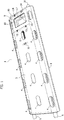
- the transverse member according to the first embodiment of the invention designated to be used to form - with similar transverse members - the loading deck of a vehicle transporter, comprises a robust elongated box-like body 1 formed by a base 2 and an upper wall 3 whose respective longitudinal edges are permanently joined to each other.
- the upper wall 3 is formed with slot-like holes 4 for the engagement of hooks for anchoring stop devices for vehicle wheels, per se known and not described in detail.
- a fixed engagement member applied transversely to an end of the box-like body 1 of the transverse member and having a pair of projecting longitudinal pins 6 suitable to cooperate with the loading deck of the vehicle transporter is indicated with 5.
- the box-like body 1 contains a movable engagement member indicated in its entirety with 7, displaceable from an advanced lock position to a receded unlock position relatively to the loading deck of the vehicle transporter, against the action of a single compression helical spring 8.
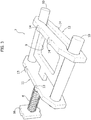
- the movable engagement member 7 consists of a latch formed by a robust annular quadrangular element 9 at whose opposite lateral edges there are fixed two cylindrical longitudinal pins 10 axially slidable through a first transverse element 11 and a second transverse element 12 spaced apart and anchored, through respective appendages 13, 14, to the walls 2 and 3 of the box-like body 1.
- a longitudinal rod 15 that traverses the first transverse element 11 and, at its free end, an abutment 16 also fixed to the walls 2, 3 of the box-like body 1.
- the compression helical spring 8 is wound on the rod 15 and reacts between the transverse guide element 11 and the abutment 16.
- the second transverse guide element 12 is positioned at the end of the transverse member opposite to the fixed engagement member 5, so that the pins 10 of the latch 7 project outside the box-like body 1, under the action of the spring 8, in an advanced lock position of the transverse member.
- the further removal of the latch 7, or the removal thereof from the transverse member, is prevented by a stop 17 for example consisting of a simple screw, suitable to abut against the transverse guide element 12 in the advanced lock position of the latch 7.
- the receding of the latch 7 from the advanced lock position to the receded unlock position, against the action of the spring 8, can be easily carried out by accessing to the quadrangular element 9 through respective windows 18, 19 formed in the walls 2, 3 of the box-like body 1.
- the second embodiment of the latch according to the invention also comprises a robust elongated box-like body 101 formed by a base or bottom wall 102 and by an upper wall 103 whose respective longitudinal edges are permanently joined to each other, for example by welding.
- the walls 102 and 103 are formed with slot-like holes 104 of which those of the upper wall 103 serve for the engagement of hooks for anchoring stop devices for vehicle wheels, per se known and not described in detail.
- a fixed engagement member applied transversely to an end of the box-like body 1 of the transverse member and having a pair of projecting longitudinal pins 106 suitable to cooperate with the loading deck of the vehicle transporter, for anchoring an end of the transverse member, is indicated with 105.
- the box-like body 101 contains a movable engagement member indicated in its entirety with 107, which - as observable hereinafter - is displaceable from an advanced lock position to a receded unlock position relatively to the loading deck of the vehicle transporter.
- the movable engagement member 107 consists in a latch formed by a robust annular quadrangular element 109 at whose opposite lateral edges there are fixed two cylindrical longitudinal pins 110 axially slidable through a first transverse element 111, double in this case, and a second transverse element 112 spaced apart and anchored, through respective appendages 113, 114, to the walls 102 and 103 of the box-like body 101.
- a central element 115 and two lateral elements 116 Projecting on the rear side of the quadrangular element 109 are a central element 115 and two lateral elements 116 which slidably traverse respective apertures of the second transverse guide element 112. Wound on the two lateral elements 116 are respective compression helical springs 117 which react against the second transverse guide element 112 for keeping the latch 107 in an advanced position in which the ends of its pins 112 project outside the box-like body 101, so as to obtain the lock condition of the transverse member relatively to the deck of the vehicle transporter.
- the latch 107 can be receded, with the aim of releasing the transverse member from the deck of the vehicle transporter, by operating manually by means of one or the other of two windows 118, 119 respectively formed in the upper wall 103 and in the base 102, up to disengaging the pins 110 from the deck against the action of the springs 117.
- the invention provides for a manually releasable safety stop, consisting of a swinging lever 120 pivoted on a central area of the quadrangular element 109 around a vertical pin 121.
- the swinging lever 120 is rotatable between an operative angular position represented in figures 1 to 4 , in which it frontally abuts against the second transverse guide element 112, and an inoperative angular position in which it does not interfere with a transverse element 112 and it thus allows the voluntary manual recession of the latch 107 against the action of the springs 117.
- a pin spring 123 wound on the pin 121 tends to hold the lever 120 stably in the operative angular position.
- a stop projecting from the quadrangular element 109 and suitable to abut, in the advanced lock position of the latch 107, against the first transverse guide element 111 is indicated with 122.
Landscapes
- Engineering & Computer Science (AREA)
- Health & Medical Sciences (AREA)
- Public Health (AREA)
- Transportation (AREA)
- Mechanical Engineering (AREA)
- Lock And Its Accessories (AREA)
Abstract
Description
- The present invention generally regards vehicle transporters and in particular it regards a loading deck consisting of removable transverse members.
- Such transverse members typically comprise an elongated box-like body, consisting of apertures for the engagement of stop devices of the vehicles transported on the vehicle transporters. The box-like body is provided - at its ends - with projecting members for engagement to the vehicle transporter, respectively fixed and mobile, and the movable engagement member consists of a latch displaceable inside the box-like body of the transverse member from an advanced lock position to a receded unlock position, against the action of thrust elastic means.
- A transverse member thus made is described and illustrated in the European patent application n°
EP-3345787A1 on behalf of the Applicant. - The object of the present invention is to provide a transverse member for loading decks of vehicle transporters capable of guaranteeing high reliability even following an extended use.
- A further object of the invention is to provide a transverse member that is particularly robust as well as efficient and flexible to use.
- A specific object of the invention is to provide a transverse member for loading decks of vehicle transporters of the type defined above that enables ensuring an optimal safety level against risks of unintentional removal arising from an inadvertent displacement of the latch from the advanced lock position to the receded unlock position.
- According to the invention, these objects are mainly attained due to the characteristics defined in
claim 1. Further secondary characteristics are indicated in the dependent claims. - The invention will now be described in detail with reference to the attached drawings, provided purely by way of non-limiting example, wherein:
-
figure 1 is a schematic perspective view of a transverse member for loading decks of vehicle transporters according to a first embodiment of the invention, -
figure 2 is an exploded perspective view of the transverse member offigure 1 , -
figure 3 is a perspective view, and in larger scale, of the mobile latch of the transverse member offigures 1 and2 , -
figure 4 is an exploded perspective view of the latch offigure 3 , -
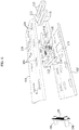
figure 5 is a schematic perspective view of a second embodiment of the transverse member for loading decks of vehicle transporters according to the invention, -
figure 6 is an exploded view offigure 5 , -
figure 7 shows - in larger scale - a detail offigure 6 , -
figure 8 perspectively shows the detail offigure 7 in a first condition or lock condition, and -
figure 9 is a view similar tofigure 8 in a second condition or unlock condition. - Initially referring to
figures 1 to 4 of the drawings, the transverse member according to the first embodiment of the invention, designated to be used to form - with similar transverse members - the loading deck of a vehicle transporter, comprises a robust elongated box-like body 1 formed by abase 2 and anupper wall 3 whose respective longitudinal edges are permanently joined to each other. - The
upper wall 3 is formed with slot-like holes 4 for the engagement of hooks for anchoring stop devices for vehicle wheels, per se known and not described in detail. - A fixed engagement member applied transversely to an end of the box-
like body 1 of the transverse member and having a pair of projectinglongitudinal pins 6 suitable to cooperate with the loading deck of the vehicle transporter is indicated with 5. - On the opposite side, the box-
like body 1 contains a movable engagement member indicated in its entirety with 7, displaceable from an advanced lock position to a receded unlock position relatively to the loading deck of the vehicle transporter, against the action of a single compressionhelical spring 8. - Referring more in detail to
figures 3 and4 , themovable engagement member 7 consists of a latch formed by a robust annularquadrangular element 9 at whose opposite lateral edges there are fixed two cylindricallongitudinal pins 10 axially slidable through a firsttransverse element 11 and a secondtransverse element 12 spaced apart and anchored, throughrespective appendages walls like body 1. - Fixed at the median area of the rear edge of the
quadrangular element 9 is alongitudinal rod 15 that traverses the firsttransverse element 11 and, at its free end, anabutment 16 also fixed to thewalls like body 1. The compressionhelical spring 8 is wound on therod 15 and reacts between thetransverse guide element 11 and theabutment 16. - The second
transverse guide element 12 is positioned at the end of the transverse member opposite to thefixed engagement member 5, so that thepins 10 of thelatch 7 project outside the box-like body 1, under the action of thespring 8, in an advanced lock position of the transverse member. The further removal of thelatch 7, or the removal thereof from the transverse member, is prevented by astop 17 for example consisting of a simple screw, suitable to abut against thetransverse guide element 12 in the advanced lock position of thelatch 7. - The receding of the
latch 7 from the advanced lock position to the receded unlock position, against the action of thespring 8, can be easily carried out by accessing to thequadrangular element 9 throughrespective windows walls like body 1. - Now, with reference to
figures 5 to 9 of the drawings, the second embodiment of the latch according to the invention also comprises a robust elongated box-like body 101 formed by a base orbottom wall 102 and by anupper wall 103 whose respective longitudinal edges are permanently joined to each other, for example by welding. - The
walls like holes 104 of which those of theupper wall 103 serve for the engagement of hooks for anchoring stop devices for vehicle wheels, per se known and not described in detail. - A fixed engagement member applied transversely to an end of the box-
like body 1 of the transverse member and having a pair of projectinglongitudinal pins 106 suitable to cooperate with the loading deck of the vehicle transporter, for anchoring an end of the transverse member, is indicated with 105. - On the opposite side, the box-
like body 101 contains a movable engagement member indicated in its entirety with 107, which - as observable hereinafter - is displaceable from an advanced lock position to a receded unlock position relatively to the loading deck of the vehicle transporter. - Referring more in detail to
figures 7 and8 , themovable engagement member 107 consists in a latch formed by a robust annularquadrangular element 109 at whose opposite lateral edges there are fixed two cylindricallongitudinal pins 110 axially slidable through a firsttransverse element 111, double in this case, and a secondtransverse element 112 spaced apart and anchored, throughrespective appendages walls like body 101. - Projecting on the rear side of the
quadrangular element 109 are acentral element 115 and twolateral elements 116 which slidably traverse respective apertures of the secondtransverse guide element 112. Wound on the twolateral elements 116 are respective compressionhelical springs 117 which react against the secondtransverse guide element 112 for keeping thelatch 107 in an advanced position in which the ends of itspins 112 project outside the box-like body 101, so as to obtain the lock condition of the transverse member relatively to the deck of the vehicle transporter. - The
latch 107 can be receded, with the aim of releasing the transverse member from the deck of the vehicle transporter, by operating manually by means of one or the other of twowindows upper wall 103 and in thebase 102, up to disengaging thepins 110 from the deck against the action of thesprings 117. - In order to make such operation voluntary, or to avoid risks of inadvertent recession of the
latch 107 towards the receded unlock position, the invention provides for a manually releasable safety stop, consisting of a swinginglever 120 pivoted on a central area of thequadrangular element 109 around avertical pin 121. The swinginglever 120 is rotatable between an operative angular position represented infigures 1 to 4 , in which it frontally abuts against the secondtransverse guide element 112, and an inoperative angular position in which it does not interfere with atransverse element 112 and it thus allows the voluntary manual recession of thelatch 107 against the action of thesprings 117. Apin spring 123 wound on thepin 121 tends to hold thelever 120 stably in the operative angular position. - A stop projecting from the
quadrangular element 109 and suitable to abut, in the advanced lock position of thelatch 107, against the firsttransverse guide element 111 is indicated with 122. - Obviously, the construction details and the embodiments may widely vary with respect to what has been described and illustrated, without departing from the scope of protection of the present invention as defined in the claims that follow.
Claims (7)
- Transverse member for the loading deck of vehicle transporters, comprising an elongated box-like body (1; 100) formed with apertures (104) for engagement of stop devices for vehicle wheels, said box-like body (101) being provided at the ends thereof with respectively a fixed and a movable projecting engaging member (105, 107), the movable engaging member (107) consisting of a latch displaceable inside the box-like body (1; 101) from an advanced lock position to a receded unlock position against the action of thrust elastic means (17; 108), characterised in that the latch (7; 107) consists of a quadrangular element (9; 109) at whose opposite lateral edges there are fixed two cylindrical pins (10, 10; 110, 110) slidable through a first and a second transverse guide element (11, 12; 111, 112) fixed inside the box-like body (1; 101) .
- Transverse member according to claim 1, characterised in that fixed at the median area of the rear edge of the quadrangular element (9) is a longitudinal rod (15) which traverses the first transverse guide element (11) and wound on which is a compression helical spring (8) reacting between said first transverse guide element (11) and an abutment (16) fixed in said box-like body (1), and the median area of the front edge of the quadrangular element (9) bearing a stop (17) suitable to abut against said second transverse guide element (12) in said advanced lock position of the latch (7).
- Transverse member according to claim 2, characterised in that said releasable safety stop (20) is accessible from outside through at least one window (18, 19) of the box-like body (1).
- Transverse member according to claim 1, characterised in that the latch (117) is provided with a safety stop (120) that can be released manually to prevent it from being displaced from the advanced position to the receded position.
- Transverse member according to claim 4, characterised in that the safety stop consists in a swinging lever (120) pivoted on said quadrangular element (109) and rotatable between an operative angular position in which it frontally abuts against said second transverse guide element (112), and an inoperative angular position, a return spring (123) being operatively associated to said swinging lever (120) tending to hold it in said operative position.
- Transverse member according to claim 5, characterised in that projecting from the rear side of said quadrangular element (109) of the latch (107) are a central element (115) and two lateral elements (116) which slidably traverse said second transverse guide element (112), respective compression helical springs (117) reacting against said second transverse guide element (112) being wound on said two lateral elements (116) .
- Transverse member according claim 5 or 6, characterised in that projecting from the front side of said quadrangular element (109) of the latch (107) is a stop (122) which is designed to abut, in said advanced lock position of the latch (107), against said first transverse guide element (111).
Applications Claiming Priority (2)
| Application Number | Priority Date | Filing Date | Title |
|---|---|---|---|
| IT202018000002249U IT201800002249U1 (en) | 2018-03-28 | 2018-03-28 | CROSSBAR FOR LOADING DECK OF BISARCHE |
| IT102018000004674A IT201800004674A1 (en) | 2018-04-18 | 2018-04-18 | CROSSBAR FOR LOADING DECK OF BISARCHE |
Publications (2)
| Publication Number | Publication Date |
|---|---|
| EP3546286A1 true EP3546286A1 (en) | 2019-10-02 |
| EP3546286B1 EP3546286B1 (en) | 2022-03-30 |
Family
ID=67733955
Family Applications (1)
| Application Number | Title | Priority Date | Filing Date |
|---|---|---|---|
| EP18208002.8A Active EP3546286B1 (en) | 2018-03-28 | 2018-11-23 | Transverse member for the loading deck of vehicle transporters |
Country Status (1)
| Country | Link |
|---|---|
| EP (1) | EP3546286B1 (en) |
Citations (4)
| Publication number | Priority date | Publication date | Assignee | Title |
|---|---|---|---|---|
| US3888191A (en) * | 1974-07-15 | 1975-06-10 | Cast Metal Ind Inc | Vehicle holddown |
| FR2725946A1 (en) * | 1994-10-24 | 1996-04-26 | Lohr Ind | Vehicle chock, for use on transporters with perforated carrying surfaces, |
| CN101817338A (en) * | 2010-05-04 | 2010-09-01 | 浙江双友物流器械股份有限公司 | Tyre stopper for automobile tyre |
| EP3345787A1 (en) | 2017-01-10 | 2018-07-11 | Officina Meccanica Migliore Livio | Transverse member for the loading deck of a vehicle transporter |
Family Cites Families (1)
| Publication number | Priority date | Publication date | Assignee | Title |
|---|---|---|---|---|
| US9079523B2 (en) * | 2013-03-04 | 2015-07-14 | Holland, L.P. | Low profile wheel chocking system and chock construction |
-
2018
- 2018-11-23 EP EP18208002.8A patent/EP3546286B1/en active Active
Patent Citations (4)
| Publication number | Priority date | Publication date | Assignee | Title |
|---|---|---|---|---|
| US3888191A (en) * | 1974-07-15 | 1975-06-10 | Cast Metal Ind Inc | Vehicle holddown |
| FR2725946A1 (en) * | 1994-10-24 | 1996-04-26 | Lohr Ind | Vehicle chock, for use on transporters with perforated carrying surfaces, |
| CN101817338A (en) * | 2010-05-04 | 2010-09-01 | 浙江双友物流器械股份有限公司 | Tyre stopper for automobile tyre |
| EP3345787A1 (en) | 2017-01-10 | 2018-07-11 | Officina Meccanica Migliore Livio | Transverse member for the loading deck of a vehicle transporter |
Also Published As
| Publication number | Publication date |
|---|---|
| EP3546286B1 (en) | 2022-03-30 |
Similar Documents
| Publication | Publication Date | Title |
|---|---|---|
| US3090600A (en) | Vehicle load retainer | |
| US9809358B2 (en) | Self-latching interbox connector for automatic securement of a top container to a bottom container | |
| US4274172A (en) | Ramps | |
| US3063667A (en) | Retractable supports for cargo | |
| US4256425A (en) | Latch assembly for dunnage bars | |
| US9702175B2 (en) | Hinge and locking device | |
| US4327501A (en) | Square adapter for level | |
| US2854132A (en) | Key case | |
| EP3546286B1 (en) | Transverse member for the loading deck of vehicle transporters | |
| US7441848B2 (en) | Automatic homing mechanism for a multi-sectional slide | |
| US4163425A (en) | Load anchoring systems for flatbed | |
| KR102102836B1 (en) | Apparatus for loading and unloading of freight | |
| US2192861A (en) | Collapsible mop | |
| CN104271411A (en) | Belt retractor, and method for locking a belt retractor | |
| US20160272102A1 (en) | Lift Platform With Lock and Release System | |
| US2279329A (en) | Ladder | |
| US2926350A (en) | Collapsible antenna | |
| US20120165161A1 (en) | Folding treadmill positioning structure | |
| IL283113B1 (en) | A device for deploying a deployable component especially a handle for a weapon system | |
| US4518184A (en) | Device for remotely passing a cord in or around an anchoring member | |
| US10549417B2 (en) | Saw horse having quick release deployable supports | |
| US4465329A (en) | Storage cabinet travel lock | |
| US2755122A (en) | Window brace | |
| NL2015815B1 (en) | A ratchet strap. | |
| US3040922A (en) | Articulated arm structure |
Legal Events
| Date | Code | Title | Description |
|---|---|---|---|
| PUAI | Public reference made under article 153(3) epc to a published international application that has entered the european phase |
Free format text: ORIGINAL CODE: 0009012 |
|
| STAA | Information on the status of an ep patent application or granted ep patent |
Free format text: STATUS: THE APPLICATION HAS BEEN PUBLISHED |
|
| AK | Designated contracting states |
Kind code of ref document: A1 Designated state(s): AL AT BE BG CH CY CZ DE DK EE ES FI FR GB GR HR HU IE IS IT LI LT LU LV MC MK MT NL NO PL PT RO RS SE SI SK SM TR |
|
| AX | Request for extension of the european patent |
Extension state: BA ME |
|
| STAA | Information on the status of an ep patent application or granted ep patent |
Free format text: STATUS: REQUEST FOR EXAMINATION WAS MADE |
|
| 17P | Request for examination filed |
Effective date: 20191231 |
|
| RBV | Designated contracting states (corrected) |
Designated state(s): AL AT BE BG CH CY CZ DE DK EE ES FI FR GB GR HR HU IE IS IT LI LT LU LV MC MK MT NL NO PL PT RO RS SE SI SK SM TR |
|
| GRAP | Despatch of communication of intention to grant a patent |
Free format text: ORIGINAL CODE: EPIDOSNIGR1 |
|
| STAA | Information on the status of an ep patent application or granted ep patent |
Free format text: STATUS: GRANT OF PATENT IS INTENDED |
|
| INTG | Intention to grant announced |
Effective date: 20211020 |
|
| GRAS | Grant fee paid |
Free format text: ORIGINAL CODE: EPIDOSNIGR3 |
|
| GRAA | (expected) grant |
Free format text: ORIGINAL CODE: 0009210 |
|
| STAA | Information on the status of an ep patent application or granted ep patent |
Free format text: STATUS: THE PATENT HAS BEEN GRANTED |
|
| AK | Designated contracting states |
Kind code of ref document: B1 Designated state(s): AL AT BE BG CH CY CZ DE DK EE ES FI FR GB GR HR HU IE IS IT LI LT LU LV MC MK MT NL NO PL PT RO RS SE SI SK SM TR |
|
| REG | Reference to a national code |
Ref country code: GB Ref legal event code: FG4D |
|
| REG | Reference to a national code |
Ref country code: CH Ref legal event code: EP |
|
| REG | Reference to a national code |
Ref country code: AT Ref legal event code: REF Ref document number: 1478897 Country of ref document: AT Kind code of ref document: T Effective date: 20220415 |
|
| REG | Reference to a national code |
Ref country code: DE Ref legal event code: R096 Ref document number: 602018032892 Country of ref document: DE |
|
| REG | Reference to a national code |
Ref country code: IE Ref legal event code: FG4D |
|
| REG | Reference to a national code |
Ref country code: LT Ref legal event code: MG9D |
|
| PG25 | Lapsed in a contracting state [announced via postgrant information from national office to epo] |
Ref country code: SE Free format text: LAPSE BECAUSE OF FAILURE TO SUBMIT A TRANSLATION OF THE DESCRIPTION OR TO PAY THE FEE WITHIN THE PRESCRIBED TIME-LIMIT Effective date: 20220330 Ref country code: RS Free format text: LAPSE BECAUSE OF FAILURE TO SUBMIT A TRANSLATION OF THE DESCRIPTION OR TO PAY THE FEE WITHIN THE PRESCRIBED TIME-LIMIT Effective date: 20220330 Ref country code: NO Free format text: LAPSE BECAUSE OF FAILURE TO SUBMIT A TRANSLATION OF THE DESCRIPTION OR TO PAY THE FEE WITHIN THE PRESCRIBED TIME-LIMIT Effective date: 20220630 Ref country code: LT Free format text: LAPSE BECAUSE OF FAILURE TO SUBMIT A TRANSLATION OF THE DESCRIPTION OR TO PAY THE FEE WITHIN THE PRESCRIBED TIME-LIMIT Effective date: 20220330 Ref country code: HR Free format text: LAPSE BECAUSE OF FAILURE TO SUBMIT A TRANSLATION OF THE DESCRIPTION OR TO PAY THE FEE WITHIN THE PRESCRIBED TIME-LIMIT Effective date: 20220330 Ref country code: BG Free format text: LAPSE BECAUSE OF FAILURE TO SUBMIT A TRANSLATION OF THE DESCRIPTION OR TO PAY THE FEE WITHIN THE PRESCRIBED TIME-LIMIT Effective date: 20220630 |
|
| REG | Reference to a national code |
Ref country code: NL Ref legal event code: MP Effective date: 20220330 |
|
| REG | Reference to a national code |
Ref country code: AT Ref legal event code: MK05 Ref document number: 1478897 Country of ref document: AT Kind code of ref document: T Effective date: 20220330 |
|
| PG25 | Lapsed in a contracting state [announced via postgrant information from national office to epo] |
Ref country code: LV Free format text: LAPSE BECAUSE OF FAILURE TO SUBMIT A TRANSLATION OF THE DESCRIPTION OR TO PAY THE FEE WITHIN THE PRESCRIBED TIME-LIMIT Effective date: 20220330 Ref country code: GR Free format text: LAPSE BECAUSE OF FAILURE TO SUBMIT A TRANSLATION OF THE DESCRIPTION OR TO PAY THE FEE WITHIN THE PRESCRIBED TIME-LIMIT Effective date: 20220701 Ref country code: FI Free format text: LAPSE BECAUSE OF FAILURE TO SUBMIT A TRANSLATION OF THE DESCRIPTION OR TO PAY THE FEE WITHIN THE PRESCRIBED TIME-LIMIT Effective date: 20220330 |
|
| PG25 | Lapsed in a contracting state [announced via postgrant information from national office to epo] |
Ref country code: NL Free format text: LAPSE BECAUSE OF FAILURE TO SUBMIT A TRANSLATION OF THE DESCRIPTION OR TO PAY THE FEE WITHIN THE PRESCRIBED TIME-LIMIT Effective date: 20220330 |
|
| PG25 | Lapsed in a contracting state [announced via postgrant information from national office to epo] |
Ref country code: SM Free format text: LAPSE BECAUSE OF FAILURE TO SUBMIT A TRANSLATION OF THE DESCRIPTION OR TO PAY THE FEE WITHIN THE PRESCRIBED TIME-LIMIT Effective date: 20220330 Ref country code: SK Free format text: LAPSE BECAUSE OF FAILURE TO SUBMIT A TRANSLATION OF THE DESCRIPTION OR TO PAY THE FEE WITHIN THE PRESCRIBED TIME-LIMIT Effective date: 20220330 Ref country code: RO Free format text: LAPSE BECAUSE OF FAILURE TO SUBMIT A TRANSLATION OF THE DESCRIPTION OR TO PAY THE FEE WITHIN THE PRESCRIBED TIME-LIMIT Effective date: 20220330 Ref country code: PT Free format text: LAPSE BECAUSE OF FAILURE TO SUBMIT A TRANSLATION OF THE DESCRIPTION OR TO PAY THE FEE WITHIN THE PRESCRIBED TIME-LIMIT Effective date: 20220801 Ref country code: ES Free format text: LAPSE BECAUSE OF FAILURE TO SUBMIT A TRANSLATION OF THE DESCRIPTION OR TO PAY THE FEE WITHIN THE PRESCRIBED TIME-LIMIT Effective date: 20220330 Ref country code: EE Free format text: LAPSE BECAUSE OF FAILURE TO SUBMIT A TRANSLATION OF THE DESCRIPTION OR TO PAY THE FEE WITHIN THE PRESCRIBED TIME-LIMIT Effective date: 20220330 Ref country code: CZ Free format text: LAPSE BECAUSE OF FAILURE TO SUBMIT A TRANSLATION OF THE DESCRIPTION OR TO PAY THE FEE WITHIN THE PRESCRIBED TIME-LIMIT Effective date: 20220330 Ref country code: AT Free format text: LAPSE BECAUSE OF FAILURE TO SUBMIT A TRANSLATION OF THE DESCRIPTION OR TO PAY THE FEE WITHIN THE PRESCRIBED TIME-LIMIT Effective date: 20220330 |
|
| PG25 | Lapsed in a contracting state [announced via postgrant information from national office to epo] |
Ref country code: PL Free format text: LAPSE BECAUSE OF FAILURE TO SUBMIT A TRANSLATION OF THE DESCRIPTION OR TO PAY THE FEE WITHIN THE PRESCRIBED TIME-LIMIT Effective date: 20220330 Ref country code: IS Free format text: LAPSE BECAUSE OF FAILURE TO SUBMIT A TRANSLATION OF THE DESCRIPTION OR TO PAY THE FEE WITHIN THE PRESCRIBED TIME-LIMIT Effective date: 20220730 Ref country code: AL Free format text: LAPSE BECAUSE OF FAILURE TO SUBMIT A TRANSLATION OF THE DESCRIPTION OR TO PAY THE FEE WITHIN THE PRESCRIBED TIME-LIMIT Effective date: 20220330 |
|
| REG | Reference to a national code |
Ref country code: DE Ref legal event code: R097 Ref document number: 602018032892 Country of ref document: DE |
|
| PG25 | Lapsed in a contracting state [announced via postgrant information from national office to epo] |
Ref country code: DK Free format text: LAPSE BECAUSE OF FAILURE TO SUBMIT A TRANSLATION OF THE DESCRIPTION OR TO PAY THE FEE WITHIN THE PRESCRIBED TIME-LIMIT Effective date: 20220330 |
|
| PLBE | No opposition filed within time limit |
Free format text: ORIGINAL CODE: 0009261 |
|
| STAA | Information on the status of an ep patent application or granted ep patent |
Free format text: STATUS: NO OPPOSITION FILED WITHIN TIME LIMIT |
|
| 26N | No opposition filed |
Effective date: 20230103 |
|
| PG25 | Lapsed in a contracting state [announced via postgrant information from national office to epo] |
Ref country code: SI Free format text: LAPSE BECAUSE OF FAILURE TO SUBMIT A TRANSLATION OF THE DESCRIPTION OR TO PAY THE FEE WITHIN THE PRESCRIBED TIME-LIMIT Effective date: 20220330 |
|
| PG25 | Lapsed in a contracting state [announced via postgrant information from national office to epo] |
Ref country code: MC Free format text: LAPSE BECAUSE OF FAILURE TO SUBMIT A TRANSLATION OF THE DESCRIPTION OR TO PAY THE FEE WITHIN THE PRESCRIBED TIME-LIMIT Effective date: 20220330 |
|
| REG | Reference to a national code |
Ref country code: CH Ref legal event code: PL |
|
| PG25 | Lapsed in a contracting state [announced via postgrant information from national office to epo] |
Ref country code: LI Free format text: LAPSE BECAUSE OF NON-PAYMENT OF DUE FEES Effective date: 20221130 Ref country code: CH Free format text: LAPSE BECAUSE OF NON-PAYMENT OF DUE FEES Effective date: 20221130 |
|
| PG25 | Lapsed in a contracting state [announced via postgrant information from national office to epo] |
Ref country code: LU Free format text: LAPSE BECAUSE OF NON-PAYMENT OF DUE FEES Effective date: 20221123 |
|
| PG25 | Lapsed in a contracting state [announced via postgrant information from national office to epo] |
Ref country code: IE Free format text: LAPSE BECAUSE OF NON-PAYMENT OF DUE FEES Effective date: 20221123 |
|
| PG25 | Lapsed in a contracting state [announced via postgrant information from national office to epo] |
Ref country code: HU Free format text: LAPSE BECAUSE OF FAILURE TO SUBMIT A TRANSLATION OF THE DESCRIPTION OR TO PAY THE FEE WITHIN THE PRESCRIBED TIME-LIMIT; INVALID AB INITIO Effective date: 20181123 |
|
| PG25 | Lapsed in a contracting state [announced via postgrant information from national office to epo] |
Ref country code: CY Free format text: LAPSE BECAUSE OF FAILURE TO SUBMIT A TRANSLATION OF THE DESCRIPTION OR TO PAY THE FEE WITHIN THE PRESCRIBED TIME-LIMIT Effective date: 20220330 |
|
| PG25 | Lapsed in a contracting state [announced via postgrant information from national office to epo] |
Ref country code: MK Free format text: LAPSE BECAUSE OF FAILURE TO SUBMIT A TRANSLATION OF THE DESCRIPTION OR TO PAY THE FEE WITHIN THE PRESCRIBED TIME-LIMIT Effective date: 20220330 |
|
| PG25 | Lapsed in a contracting state [announced via postgrant information from national office to epo] |
Ref country code: MT Free format text: LAPSE BECAUSE OF FAILURE TO SUBMIT A TRANSLATION OF THE DESCRIPTION OR TO PAY THE FEE WITHIN THE PRESCRIBED TIME-LIMIT Effective date: 20220330 |
|
| PG25 | Lapsed in a contracting state [announced via postgrant information from national office to epo] |
Ref country code: TR Free format text: LAPSE BECAUSE OF FAILURE TO SUBMIT A TRANSLATION OF THE DESCRIPTION OR TO PAY THE FEE WITHIN THE PRESCRIBED TIME-LIMIT Effective date: 20220330 |
|
| PGFP | Annual fee paid to national office [announced via postgrant information from national office to epo] |
Ref country code: DE Payment date: 20251126 Year of fee payment: 8 |
|
| PGFP | Annual fee paid to national office [announced via postgrant information from national office to epo] |
Ref country code: GB Payment date: 20251125 Year of fee payment: 8 |
|
| PGFP | Annual fee paid to national office [announced via postgrant information from national office to epo] |
Ref country code: IT Payment date: 20251107 Year of fee payment: 8 |
|
| PGFP | Annual fee paid to national office [announced via postgrant information from national office to epo] |
Ref country code: FR Payment date: 20251124 Year of fee payment: 8 |
|
| PGFP | Annual fee paid to national office [announced via postgrant information from national office to epo] |
Ref country code: BE Payment date: 20251124 Year of fee payment: 8 |