EP3345787A1 - Transverse member for the loading deck of a vehicle transporter - Google Patents
Transverse member for the loading deck of a vehicle transporter Download PDFInfo
- Publication number
- EP3345787A1 EP3345787A1 EP18150634.6A EP18150634A EP3345787A1 EP 3345787 A1 EP3345787 A1 EP 3345787A1 EP 18150634 A EP18150634 A EP 18150634A EP 3345787 A1 EP3345787 A1 EP 3345787A1
- Authority
- EP
- European Patent Office
- Prior art keywords
- box
- latch
- transverse member
- fitted
- bolt
- Prior art date
- Legal status (The legal status is an assumption and is not a legal conclusion. Google has not performed a legal analysis and makes no representation as to the accuracy of the status listed.)
- Withdrawn
Links
- 230000005764 inhibitory process Effects 0.000 claims description 3
- 230000002401 inhibitory effect Effects 0.000 claims 1
- 238000010276 construction Methods 0.000 description 2
- 238000004519 manufacturing process Methods 0.000 description 2
- 238000004873 anchoring Methods 0.000 description 1
- 230000006835 compression Effects 0.000 description 1
- 238000007906 compression Methods 0.000 description 1
- 230000037431 insertion Effects 0.000 description 1
- 238000003780 insertion Methods 0.000 description 1
- 238000003698 laser cutting Methods 0.000 description 1
Images


Classifications
-
- B—PERFORMING OPERATIONS; TRANSPORTING
- B60—VEHICLES IN GENERAL
- B60P—VEHICLES ADAPTED FOR LOAD TRANSPORTATION OR TO TRANSPORT, TO CARRY, OR TO COMPRISE SPECIAL LOADS OR OBJECTS
- B60P3/00—Vehicles adapted to transport, to carry or to comprise special loads or objects
- B60P3/06—Vehicles adapted to transport, to carry or to comprise special loads or objects for carrying vehicles
- B60P3/07—Vehicles adapted to transport, to carry or to comprise special loads or objects for carrying vehicles for carrying road vehicles
- B60P3/073—Vehicle retainers
- B60P3/075—Vehicle retainers for wheels, hubs, or axle shafts
- B60P3/077—Wheel cradles, chocks, or wells
Definitions
- the present invention generally regards vehicle transporters and in particular it regards a loading deck made up of removable transverse members.
- transverse members typically comprise an elongated box-like body formed at the upper part with apertures for engaging a device for stopping vehicle wheels, and provided - at the ends thereof - with respectively fixed and movable members for engagement to the vehicle transporter, which enable the quick fitting and removal of the transverse member.
- the movable engagement member of the transverse member is constituted by a releasable latch biased by a spring fitted into the box-like body and displaceable from an advanced position to a receded position relative to the box-like body, against the action of the spring.
- the transverse member is provided with means for preventing the removal of the latch from the box-like body which, in a currently applied solution, consist of springing hindering appendages integrally formed on the sides of the latch, for example obtained through laser-cutting.
- the object of the present invention is to overcome the aforementioned drawback and provide a transverse member for the loading deck of a vehicle transporter of the type described above that is easy and economic to manufacture and capable of guaranteeing maximum safety against the risk of inadvertent exit of the latch from the body of the transverse member.
- the aforementioned inhibition means consist of a bolt formed by a screw fitted through a hole of the upper side of the box-like body and a through hole of the latch, and a nut fitted through a hole of the lower side of the box-like body and screwed with the screw.
- the bolt is contained in a cavity of the body of the transverse member and, in the advanced position of the latch, it abuts against the end wall of the box-like body.
- the manufacturing of the latch, and thus of the transverse member is considerably simpler even considering the fact that the holes through which the screw and the nut are fitted are usually provided for on the upper side and on the lower side of the box-like body of the transverse member. Furthermore, the bolt which serves as a stop for the latch when the latter is in the advanced position is considerably more robust with respect to the aforementioned inhibition systems of the prior art, thus offering greater safety and reliability in use.
- the transverse member according to the invention designated to be used to form - with similar transverse members - the loading deck of a vehicle transporter, comprises a robust elongated box-like body 1 having a base 2, an upper wall 3 and end walls 4, 5.
- the upper wall 3 is formed with slot-like holes 6 for the engagement of hooks for anchoring stop devices, for vehicle wheels, per se known and not described in detail.
- a fixed engagement member 7 designated to be engaged with the structure of the loading deck of the vehicle transporter projects from the end wall 4.
- a movable engagement member 8 constituted by a releasable latch, shown in detail in figures 6 and 7 , permanently fitted into the box-like body 1 and displaceable from an advanced position to a receded position against the action of a compression helical spring 9, projects from the other end wall 5.
- the latch 8 is formed by a robust annular element 10 from whose one end the notches 11 traversing the end wall 5 of the transverse member 1 project for the releasable engagement with the structure of the loading deck of the vehicle transporter, and from whose opposite end a stem 12 on which the helical spring 9 is wound, extends.
- the end of the latch 8 from which the notches 11 project is also formed with an inner appendage 13 having a vertical through hole 19 for the insertion of a bolt 14.
- the bolt 14 comprises a screw, whose head is indicated with 15, and a nut 16.
- the head of the screw 15 and the nut 16 abut - from within the transverse member 1 - against the end wall 5 of the body 1, thus preventing the inadvertent exit and unintentional removal of the latch 8 from the transverse member 1.
- the latch 8 As regards the mounting of the latch 8, it is firstly inserted into the transverse member 1 and then aligned between the through hole 19 of the appendage 13 and a pair of holes 17, 18 respectively provided for on the lower wall 2 and on the upper wall 3 of the box-like body 1. These two holes 17, 18 are normally provided previously, hence the application of the bolt 14 does not entail any particular complications. Once the latch 8 has been mounted, it is pushed by the spring 9 to the advanced position thereof in which, as mentioned, its exit from the transverse member is prevented by the bolt 14.
Landscapes
- Engineering & Computer Science (AREA)
- Health & Medical Sciences (AREA)
- Public Health (AREA)
- Transportation (AREA)
- Mechanical Engineering (AREA)
- Fittings On The Vehicle Exterior For Carrying Loads, And Devices For Holding Or Mounting Articles (AREA)
- Pharmaceuticals Containing Other Organic And Inorganic Compounds (AREA)
- Nitrogen Condensed Heterocyclic Rings (AREA)
- Management, Administration, Business Operations System, And Electronic Commerce (AREA)
Abstract
Transverse member for the loading deck of a vehicle transporter comprising an elongated box-like body (1) from whose end walls (4, 5) respectively fixed and movable engagement members (7, 8) project. The movable engagement member is constituted by a releasable latch (8) biased by a spring (9) whose removal from the box-like body (1) is prevented by a bolt (14) which abuts against the corresponding end wall (5) of the box-like body (1) in the advanced position of the latch (8).
Description
- The present invention generally regards vehicle transporters and in particular it regards a loading deck made up of removable transverse members. Such transverse members typically comprise an elongated box-like body formed at the upper part with apertures for engaging a device for stopping vehicle wheels, and provided - at the ends thereof - with respectively fixed and movable members for engagement to the vehicle transporter, which enable the quick fitting and removal of the transverse member.
- Typically, the movable engagement member of the transverse member is constituted by a releasable latch biased by a spring fitted into the box-like body and displaceable from an advanced position to a receded position relative to the box-like body, against the action of the spring. Furthermore, the transverse member is provided with means for preventing the removal of the latch from the box-like body which, in a currently applied solution, consist of springing hindering appendages integrally formed on the sides of the latch, for example obtained through laser-cutting. Once the latch has been fitted into the box-like body of the transverse member, these appendages abut, in the advanced position of the latch, against the wall of the corresponding end of the transverse member.
- Besides being expensive from a construction point of view, this solution is poorly reliable due to the risk of the springing appendages breaking.
- The object of the present invention is to overcome the aforementioned drawback and provide a transverse member for the loading deck of a vehicle transporter of the type described above that is easy and economic to manufacture and capable of guaranteeing maximum safety against the risk of inadvertent exit of the latch from the body of the transverse member.
- According to the invention, this object is attained due to the fact that the aforementioned inhibition means consist of a bolt formed by a screw fitted through a hole of the upper side of the box-like body and a through hole of the latch, and a nut fitted through a hole of the lower side of the box-like body and screwed with the screw. The bolt is contained in a cavity of the body of the transverse member and, in the advanced position of the latch, it abuts against the end wall of the box-like body.
- Thanks to this solution idea, the manufacturing of the latch, and thus of the transverse member, is considerably simpler even considering the fact that the holes through which the screw and the nut are fitted are usually provided for on the upper side and on the lower side of the box-like body of the transverse member. Furthermore, the bolt which serves as a stop for the latch when the latter is in the advanced position is considerably more robust with respect to the aforementioned inhibition systems of the prior art, thus offering greater safety and reliability in use.
- The invention will now be described in detail with reference to the attached drawings, provided purely by way of non-limiting example, wherein:
-
figure 1 is a schematic perspective view of a transverse member for loading decks of vehicle transporters according to the invention, -
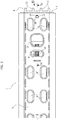
figure 2 is a top plan view offigure 1 , -
figure 3 is a front elevational view according to arrow III offigure 2 , -
figure 4 is a longitudinal sectional view according to line IV-IV offigure 2 , -
figure 5 is a cross-sectional view according to line V-V offigure 4 , -
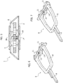
figures 6 and 7 are two respectively top and bottom perspective views of the latch of the transverse member. - Initially referring to
figures 1 and2 , the transverse member according to the invention, designated to be used to form - with similar transverse members - the loading deck of a vehicle transporter, comprises a robust elongated box-like body 1 having abase 2, anupper wall 3 andend walls - The
upper wall 3 is formed with slot-like holes 6 for the engagement of hooks for anchoring stop devices, for vehicle wheels, per se known and not described in detail. - A fixed
engagement member 7 designated to be engaged with the structure of the loading deck of the vehicle transporter projects from theend wall 4. Amovable engagement member 8 constituted by a releasable latch, shown in detail infigures 6 and 7 , permanently fitted into the box-like body 1 and displaceable from an advanced position to a receded position against the action of a compressionhelical spring 9, projects from theother end wall 5. - Referring further in detail to
figures 6 and 7 , thelatch 8 is formed by a robustannular element 10 from whose one end thenotches 11 traversing theend wall 5 of thetransverse member 1 project for the releasable engagement with the structure of the loading deck of the vehicle transporter, and from whose opposite end astem 12 on which thehelical spring 9 is wound, extends. - The end of the
latch 8 from which thenotches 11 project is also formed with aninner appendage 13 having a vertical throughhole 19 for the insertion of abolt 14. - The
bolt 14 comprises a screw, whose head is indicated with 15, and anut 16. In the advanced position of thelatch 8, the head of thescrew 15 and thenut 16 abut - from within the transverse member 1 - against theend wall 5 of thebody 1, thus preventing the inadvertent exit and unintentional removal of thelatch 8 from thetransverse member 1. - As regards the mounting of the
latch 8, it is firstly inserted into thetransverse member 1 and then aligned between the throughhole 19 of theappendage 13 and a pair ofholes lower wall 2 and on theupper wall 3 of the box-like body 1. These twoholes bolt 14 does not entail any particular complications. Once thelatch 8 has been mounted, it is pushed by thespring 9 to the advanced position thereof in which, as mentioned, its exit from the transverse member is prevented by thebolt 14. - Obviously, the construction details and the embodiments may widely vary with respect to what has been described and illustrated, without departing from the scope of protection of the invention as described in the claim that follows.
Claims (1)
- Transverse member for the loading deck of a vehicle transporter, comprising an elongated box-like body (1) formed on the upper side (3) thereof with apertures (6) for the engagement of a stop device for vehicle wheels, said box-like body (1) being provided with end walls (4, 5) from which respectively fixed and movable members (7, 8) for engagement to the vehicle transporter project, the movable engagement member being constituted by a releasable latch (8) biased by a spring (9), fitted within the box-like body (1) and displaceable from an advanced position to a receded position relative to the box-like body (1) against the action of said spring (9), and wherein means for inhibiting the removal of the latch (8) from the box-like body (1) of the transverse member are provided, characterised in that said inhibition means consist of a bolt (14) formed by a screw (15) fitted through a hole (18) of the upper side (3) of the box-like body (1) and a through hole (19) of the latch (8), and a nut (16) fitted through a hole (17) of the lower side (2) of the box-like body (1), said bolt (14) abutting against the corresponding end wall (5) of the box-like body (1) in the advanced position of the latch (8).
Applications Claiming Priority (1)
| Application Number | Priority Date | Filing Date | Title |
|---|---|---|---|
| IT102017000001791A IT201700001791A1 (en) | 2017-01-10 | 2017-01-10 | CROSSBAR FOR BISARCHE LOADING PLAN |
Publications (1)
| Publication Number | Publication Date |
|---|---|
| EP3345787A1 true EP3345787A1 (en) | 2018-07-11 |
Family
ID=58671808
Family Applications (1)
| Application Number | Title | Priority Date | Filing Date |
|---|---|---|---|
| EP18150634.6A Withdrawn EP3345787A1 (en) | 2017-01-10 | 2018-01-08 | Transverse member for the loading deck of a vehicle transporter |
Country Status (2)
| Country | Link |
|---|---|
| EP (1) | EP3345787A1 (en) |
| IT (1) | IT201700001791A1 (en) |
Cited By (1)
| Publication number | Priority date | Publication date | Assignee | Title |
|---|---|---|---|---|
| EP3546286A1 (en) | 2018-03-28 | 2019-10-02 | Officina Meccanica Migliore Livio | Transverse member for the loading deck of vehicle transporters |
Citations (3)
| Publication number | Priority date | Publication date | Assignee | Title |
|---|---|---|---|---|
| US3841235A (en) * | 1973-04-05 | 1974-10-15 | Broderick & Bascom Rope Co | Wheeled vehicle tie-down device |
| US3888191A (en) * | 1974-07-15 | 1975-06-10 | Cast Metal Ind Inc | Vehicle holddown |
| US20140248102A1 (en) * | 2013-03-04 | 2014-09-04 | Andrew J. Morin | Low Profile Wheel Chocking System and Chock Construction |
-
2017
- 2017-01-10 IT IT102017000001791A patent/IT201700001791A1/en unknown
-
2018
- 2018-01-08 EP EP18150634.6A patent/EP3345787A1/en not_active Withdrawn
Patent Citations (3)
| Publication number | Priority date | Publication date | Assignee | Title |
|---|---|---|---|---|
| US3841235A (en) * | 1973-04-05 | 1974-10-15 | Broderick & Bascom Rope Co | Wheeled vehicle tie-down device |
| US3888191A (en) * | 1974-07-15 | 1975-06-10 | Cast Metal Ind Inc | Vehicle holddown |
| US20140248102A1 (en) * | 2013-03-04 | 2014-09-04 | Andrew J. Morin | Low Profile Wheel Chocking System and Chock Construction |
Cited By (1)
| Publication number | Priority date | Publication date | Assignee | Title |
|---|---|---|---|---|
| EP3546286A1 (en) | 2018-03-28 | 2019-10-02 | Officina Meccanica Migliore Livio | Transverse member for the loading deck of vehicle transporters |
Also Published As
| Publication number | Publication date |
|---|---|
| IT201700001791A1 (en) | 2018-07-10 |
Similar Documents
| Publication | Publication Date | Title |
|---|---|---|
| US9882365B2 (en) | Cradle clamp bracket assembly | |
| US9205553B2 (en) | Tool suspension device | |
| AU2016228214B2 (en) | Tensioning device for chains | |
| US6733221B2 (en) | Insert nut for a screw nut joint | |
| EP3345787A1 (en) | Transverse member for the loading deck of a vehicle transporter | |
| US3241799A (en) | Apertured panel hook lock | |
| RU2686568C2 (en) | Tow recovery eye and tow system of vehicle | |
| US20150294605A1 (en) | Truck Bed Stake Pocket Flag Pole Mount | |
| EP1980444A2 (en) | Fixing device for additional mats in a motor vehicle | |
| WO2013064149A1 (en) | Means for strapping a load on a transport platform | |
| US20140376997A1 (en) | System enabling the attachment of an object to an element having attachment groove(s), and attachment device for such a system | |
| GB2501227A (en) | A coupler for connecting a scaffolding element to a vertical scaffold member | |
| US9642279B2 (en) | Rail mounting structure | |
| US2408366A (en) | Toggle bolt | |
| KR101278828B1 (en) | Connector for aluminium profile | |
| WO2014188148A1 (en) | Ground stabilising arrangement | |
| US20180213935A1 (en) | Impact protection device clip | |
| EP3287317B1 (en) | Semitrailer side edge including elements allowing for cargo locking | |
| US20140090237A1 (en) | Device for securing a cap screw to an element that is to be attached to another element | |
| US1732033A (en) | Cable clamp | |
| US9233721B2 (en) | Coupling assembly | |
| EP2881596B1 (en) | Mounting wedge | |
| US20060283434A1 (en) | Metal support column shipping assembly | |
| US20070175703A1 (en) | Scaffold deck and self-locking hook | |
| US1629503A (en) | Lock nut |
Legal Events
| Date | Code | Title | Description |
|---|---|---|---|
| PUAI | Public reference made under article 153(3) epc to a published international application that has entered the european phase |
Free format text: ORIGINAL CODE: 0009012 |
|
| AK | Designated contracting states |
Kind code of ref document: A1 Designated state(s): AL AT BE BG CH CY CZ DE DK EE ES FI FR GB GR HR HU IE IS IT LI LT LU LV MC MK MT NL NO PL PT RO RS SE SI SK SM TR |
|
| AX | Request for extension of the european patent |
Extension state: BA ME |
|
| STAA | Information on the status of an ep patent application or granted ep patent |
Free format text: STATUS: THE APPLICATION HAS BEEN WITHDRAWN |
|
| 18W | Application withdrawn |
Effective date: 20180927 |