EP3546285A1 - Automobile headrest and automobile seat - Google Patents
Automobile headrest and automobile seat Download PDFInfo
- Publication number
- EP3546285A1 EP3546285A1 EP18873668.0A EP18873668A EP3546285A1 EP 3546285 A1 EP3546285 A1 EP 3546285A1 EP 18873668 A EP18873668 A EP 18873668A EP 3546285 A1 EP3546285 A1 EP 3546285A1
- Authority
- EP
- European Patent Office
- Prior art keywords
- speaker
- cavity
- cover board
- automotive
- automotive headrest
- Prior art date
- Legal status (The legal status is an assumption and is not a legal conclusion. Google has not performed a legal analysis and makes no representation as to the accuracy of the status listed.)
- Granted
Links
Images
Classifications
-
- B—PERFORMING OPERATIONS; TRANSPORTING
- B60—VEHICLES IN GENERAL
- B60N—SEATS SPECIALLY ADAPTED FOR VEHICLES; VEHICLE PASSENGER ACCOMMODATION NOT OTHERWISE PROVIDED FOR
- B60N2/00—Seats specially adapted for vehicles; Arrangement or mounting of seats in vehicles
- B60N2/80—Head-rests
- B60N2/879—Head-rests with additional features not related to head-rest positioning, e.g. heating or cooling devices or loudspeakers
-
- H—ELECTRICITY
- H04—ELECTRIC COMMUNICATION TECHNIQUE
- H04R—LOUDSPEAKERS, MICROPHONES, GRAMOPHONE PICK-UPS OR LIKE ACOUSTIC ELECTROMECHANICAL TRANSDUCERS; ELECTRIC HEARING AIDS; PUBLIC ADDRESS SYSTEMS
- H04R1/00—Details of transducers, loudspeakers or microphones
- H04R1/02—Casings; Cabinets ; Supports therefor; Mountings therein
- H04R1/025—Arrangements for fixing loudspeaker transducers, e.g. in a box, furniture
-
- H—ELECTRICITY
- H04—ELECTRIC COMMUNICATION TECHNIQUE
- H04R—LOUDSPEAKERS, MICROPHONES, GRAMOPHONE PICK-UPS OR LIKE ACOUSTIC ELECTROMECHANICAL TRANSDUCERS; ELECTRIC HEARING AIDS; PUBLIC ADDRESS SYSTEMS
- H04R1/00—Details of transducers, loudspeakers or microphones
- H04R1/20—Arrangements for obtaining desired frequency or directional characteristics
- H04R1/32—Arrangements for obtaining desired frequency or directional characteristics for obtaining desired directional characteristic only
- H04R1/40—Arrangements for obtaining desired frequency or directional characteristics for obtaining desired directional characteristic only by combining a number of identical transducers
- H04R1/403—Arrangements for obtaining desired frequency or directional characteristics for obtaining desired directional characteristic only by combining a number of identical transducers loud-speakers
-
- H—ELECTRICITY
- H04—ELECTRIC COMMUNICATION TECHNIQUE
- H04R—LOUDSPEAKERS, MICROPHONES, GRAMOPHONE PICK-UPS OR LIKE ACOUSTIC ELECTROMECHANICAL TRANSDUCERS; ELECTRIC HEARING AIDS; PUBLIC ADDRESS SYSTEMS
- H04R3/00—Circuits for transducers
- H04R3/12—Circuits for transducers for distributing signals to two or more loudspeakers
-
- H—ELECTRICITY
- H04—ELECTRIC COMMUNICATION TECHNIQUE
- H04R—LOUDSPEAKERS, MICROPHONES, GRAMOPHONE PICK-UPS OR LIKE ACOUSTIC ELECTROMECHANICAL TRANSDUCERS; ELECTRIC HEARING AIDS; PUBLIC ADDRESS SYSTEMS
- H04R2499/00—Aspects covered by H04R or H04S not otherwise provided for in their subgroups
- H04R2499/10—General applications
- H04R2499/13—Acoustic transducers and sound field adaptation in vehicles
Definitions
- the present invention relates to the field of automotive spare parts, in particular to an automotive headrest and an automotive seat.
- the existing automotive seat mainly includes a backrest and a headrest, and the headrest is mounted on the automotive seat.
- most of the traditional automotive seats do not have a sounding unit, and when the occupants need to listen to music and answer the phone, it is generally realized by car audio. However, this way has the problem of poor privacy.
- Chinese Patent CN206141387U provides an automotive electronic headrest comprising a headrest frame, a main headrest and two side headrests, the headrest frame comprising a main support and two side extension supports connected to opposite sides of the main support, the main headrest being sheathed on the main support, and the two side head headrests being respectively sheathed on the corresponding side extension supports.
- Each of the side headrests is provided with at least one audio assembly and at least one microphone assembly.
- the present invention is intended to provide an improved automotive headrest and an automotive seat with this improved automotive headrest, which has good privacy, a simple structure, a small size, and a good visual field.
- the present invention provides an automotive headrest comprising a support and a headrest body disposed on the support, the headrest body has a first cavity and a second cavity independent of another, and the first cavity and the second cavity are provided with a speaker unit respectively, and the two speaker units are located on the left and right sides of the headrest body respectively.
- the headrest body comprises a front cover board, a left side portion of the front cover board has a left mounting portion, and a right side portion of the front cover board has a right mounting portion, each of the speaker units respectively comprises a speaker, and the left mounting portion is provided with a left mounting hole communicating with the first cavity, the right mounting portion is provided with a right mounting hole communicating with the second cavity, and the speaker on the left side is mounted in the left mounting hole, and the speaker on the right side is mounted in the right mounting hole.
- the left mounting portion is further provided with a left echo tube, which extends through the left mounting portion and extends rearward to communicate with the first cavity
- the right mounting portion is further provided with a right echo tube, which extends through the right mounting portion and extends rearward to communicate with the second cavity.
- each of the speaker units further comprises a mesh cover, a sound gathering cover and a speaker cover board sequentially provided on a front surface of the speaker, the mesh cover is covered on the front surface of the speaker, positions on the sound gathering cover and the speaker cover board corresponding to the mesh cover are respectively provided with through holes for sound propagation.
- a center line of the through hole of the speaker unit on the left side and a center line of the through hole of the speaker unit on the left side forms an angle greater than 0 and less than 180 degrees with a traveling direction of an automobile respectively.
- both the angles are 45 degrees.
- the speaker unit on the left side and the speaker unit on the right side are symmetrical.
- shapes of a left portion and a right portion of the front cover board are adapted to a left rear side and a right rear side of a head of an occupant respectively.
- the left portion of the front cover board gradually extends forward from a middle part of the front cover board to a left edge thereof
- the right portion of the front cover board gradually extends forward from a middle part of the front cover board to a right edge thereof.
- first cavity and the second cavity are filled with a sound absorbing material (such as sound-absorbing cotton).
- the present invention provides an automotive seat comprising a backrest, and it further comprises the above mentioned automotive headrest, and the automotive headrest is disposed on an upper portion of the backrest.
- the present invention has the following advantages over the prior art: by arranging the speaker unit at the left and right sides of the headrest respectively, only one headrest can realize the function, which has good privacy, simple structure, small size, low cost, high comfort, and good visual field.
- orientation words mentioned in the present invention are defined by the conventional viewing angle of the headrest.
- “left” and “right” correspond to the left side and the right side of the paper surface in Fig. 1 , respectively
- “front” and “rear” are defined according to the traveling direction of an automobile.
- the present embodiment provides an automotive seat comprising a backrest and an automotive headrest disposed on an upper portion of the backrest.
- the automotive headrest comprises a support 200 and a headrest body 100 disposed on the support 200, and a lower portion of the support 200 is fixedly connected to the backrest, and an upper portion of the support 200 is fixedly connected to the headrest body 100.
- Fig. 1 - 5 the automotive headrest comprises a support 200 and a headrest body 100 disposed on the support 200, and a lower portion of the support 200 is fixedly connected to the backrest, and an upper portion of the support 200 is fixedly connected to the headrest body 100.
- the support 200 is a rod of an inverted U shape, an upper end portion of the support 200 is located within the headrest body 100, and two end portions of the support 200 extend out from a lower portion of the headrest body 100, and the left and right lower end portions of the support 200 and the headrest body 100 are seal fitted via a left seal gasket 113 and a right seal gasket 114, respectively.
- the headrest body is provided with a first cavity and a second cavity mutually independent, the first cavity and the second cavity are provided with a speaker unit respectively, the two speaker units are located on left and right sides of the headrest body respectively, and the speaker unit on the left side and the speaker unit on the right side are bilaterally symmetrical with respect to a central line of the headrest body in an up-down direction (shown by a straight line C in Fig. 1 ). Due to that the first cavity and the second cavity are mutually independent, the two are not communicated with each other, and prevent the sound of the speaker units provided in the two cavities from rewinding, as shown in Fig. 3 .
- the headrest body also has other cavities therein, and all cavities including the first cavity and the second cavity are filled with sound absorbing materials such as sound-absorbing cotton, thereby reducing the sound pressure level of the two sides and the back.
- the pillow body 100 comprises a rear cover board 101 and a front cover board 102 that are connected with each other, and a left cover board 105 and a right cover board 106 for closing the rear cover board 101 and the front cover board 102.
- a left partition board 103 is disposed between the left side portions of the rear cover board 101 and the front cover board 102 to form the independent first cavity between the front cover board 102, the left cover board 105 and the left partition board 103;
- a right partition board 104 is disposed between the right side portions of the rear cover board 101 and the front cover board 102 to form the independent second cavity between the front cover board 102, the right cover board 106 and the right partition board 104; the front and rear cavities are partitioned by the left partition board 103 and the right partition board 104 to further reduce the sound pressure level of the back.
- the shapes of the left portion and the right portion of the front cover board 102 are adapted to a left rear side and a right rear side of the head of an occupant respectively, specifically are arc-shaped, so that the left portion of the front cover board 102 gradually extends forward from a middle part of the front cover board 102 to a left edge thereof, and the right portion of the front cover board 102 gradually extends forward from a middle part of the front cover board 102 to a right edge thereof, that is, the left and right edges of the front cover board 102 are slightly convex forward, and can block the sound of the speaker from propagating to the outside, and are more comfortable without blocking the viewing field at the same time.
- the left side portion and the right side portion of the front cover board 102 have a left mounting portion 117 and a right mounting portion 118 respectively, each of the speaker units comprises a speaker 115 or 116 respectively, and the left mounting portion 117 is provided with a mounting hole 117a communicating with the first cavity, and the right mounting portion 118 are provided with a right mounting hole 118a communicating with the second cavity, and the left speaker 115 is mounted within the left mounting hole 117a, and the right speaker 116 is mounted within the right mounting hole 118a. As shown in Figs.
- the left mounting portion 117 is further provided with a left echo tube 119, which passes through the left mounting portion 117 and extends rearwardly to communicate with the first cavity
- the right mounting portion 118 is further provided with a right echo tube 120, which passes through the right mounting portion 118 and extends rearwardly to communicate with the second cavity.
- the left speaker units further comprises a left mesh cover 107, a left sound gathering cover 109 and a left speaker cover board 111 sequentially provided on a front surface of the left speaker 115;
- the right speaker units further comprises a right mesh cover 108, a right sound gathering cover 110 and a right speaker cover board 112 sequentially provided on a front surface of the right speaker 116; wherein, the mesh covers are covered on the front surfaces of the speakers, positions on the sound gathering covers and the speaker cover boards corresponding to the mesh covers are provided with through holes 121 for sound propagation respectively.
- the sound gathering covers form a sound gathering structure, so that the sound emitted by the left speaker 115 and the right speaker 116 is more directional.
- a center line of the through hole 121 of the left speaker unit 115 and a center line of the through hole 121 of the left speaker unit 116 forms an angle greater than 0 and less than 180 degrees with a traveling direction of an automobile respectively, in particular, both the angles on the two sides are 45 degrees. That is, the pointing angles of the speaker are positioned at 45 degrees. According to the suitable range of different kinds of human ear, the measurements are averaged.
- the automotive headrest provided by the present embodiment has no DSP (digital signal processing) algorithm, and physical decompression and the control of the sound pressure level are achieved only through the design of the structure, thereby canceling out the sound and reducing the cost.
- the left speaker 115 and the right speaker 116 are positioned as close as possible to the ear, and can also be assisted by other devices that gather sound close to the ear, such as sleeving a headset soft cover over the speakers.
- connections between the components of the headrest body, between the components of the speakers, and between the headrest components and the speaker components employ detachably connection via hook components, and also may utilize other connection manners such as glue fixing.
- the automotive headrest provided by the present embodiment has the following advantages: the function of the private conversation can be realized only by the structural design, as shown in the performance test data in FIG. 6 ; the cost is low, the development of the DSP algorithm is not required, and the sound pressure is reduced only by the physical method, the shape is simple and comfortable, and the function can be realized by only one headrest, and the material cost is low.
Landscapes
- Engineering & Computer Science (AREA)
- Health & Medical Sciences (AREA)
- Otolaryngology (AREA)
- Physics & Mathematics (AREA)
- Acoustics & Sound (AREA)
- Signal Processing (AREA)
- Mechanical Engineering (AREA)
- Aviation & Aerospace Engineering (AREA)
- Transportation (AREA)
- General Health & Medical Sciences (AREA)
- Chair Legs, Seat Parts, And Backrests (AREA)
- Seats For Vehicles (AREA)
- Fittings On The Vehicle Exterior For Carrying Loads, And Devices For Holding Or Mounting Articles (AREA)
Abstract
Description
- The present application claims priority from Chinese Patent Application No.
CN201721450022.3 - The present invention relates to the field of automotive spare parts, in particular to an automotive headrest and an automotive seat.
- The existing automotive seat mainly includes a backrest and a headrest, and the headrest is mounted on the automotive seat. At present, most of the traditional automotive seats do not have a sounding unit, and when the occupants need to listen to music and answer the phone, it is generally realized by car audio. However, this way has the problem of poor privacy.
- Aiming at this problem, Chinese Patent
CN206141387U provides an automotive electronic headrest comprising a headrest frame, a main headrest and two side headrests, the headrest frame comprising a main support and two side extension supports connected to opposite sides of the main support, the main headrest being sheathed on the main support, and the two side head headrests being respectively sheathed on the corresponding side extension supports. Each of the side headrests is provided with at least one audio assembly and at least one microphone assembly. Although the automotive electronic headrest provided by the this patent solves the above problems to some extent, it has two side headrests, which results in a large overall volume of the headrest, which wastes cost and affects the appearance, especially affects visual field on the left and right sides. - Aiming at the above mentioned problems, the present invention is intended to provide an improved automotive headrest and an automotive seat with this improved automotive headrest, which has good privacy, a simple structure, a small size, and a good visual field.
- According to one aspect of the present invention, the present invention provides an automotive headrest comprising a support and a headrest body disposed on the support, the headrest body has a first cavity and a second cavity independent of another, and the first cavity and the second cavity are provided with a speaker unit respectively, and the two speaker units are located on the left and right sides of the headrest body respectively.
- Further, the headrest body comprises a front cover board, a left side portion of the front cover board has a left mounting portion, and a right side portion of the front cover board has a right mounting portion, each of the speaker units respectively comprises a speaker, and the left mounting portion is provided with a left mounting hole communicating with the first cavity, the right mounting portion is provided with a right mounting hole communicating with the second cavity, and the speaker on the left side is mounted in the left mounting hole, and the speaker on the right side is mounted in the right mounting hole.
- Further, the left mounting portion is further provided with a left echo tube, which extends through the left mounting portion and extends rearward to communicate with the first cavity, and the right mounting portion is further provided with a right echo tube, which extends through the right mounting portion and extends rearward to communicate with the second cavity.
- Further, each of the speaker units further comprises a mesh cover, a sound gathering cover and a speaker cover board sequentially provided on a front surface of the speaker, the mesh cover is covered on the front surface of the speaker, positions on the sound gathering cover and the speaker cover board corresponding to the mesh cover are respectively provided with through holes for sound propagation.
- Further, a center line of the through hole of the speaker unit on the left side and a center line of the through hole of the speaker unit on the left side forms an angle greater than 0 and less than 180 degrees with a traveling direction of an automobile respectively.
- More further, both the angles are 45 degrees.
- Further, the speaker unit on the left side and the speaker unit on the right side are symmetrical.
- Further, the shapes of a left portion and a right portion of the front cover board are adapted to a left rear side and a right rear side of a head of an occupant respectively.
- Further, the left portion of the front cover board gradually extends forward from a middle part of the front cover board to a left edge thereof, and the right portion of the front cover board gradually extends forward from a middle part of the front cover board to a right edge thereof.
- Further, the first cavity and the second cavity are filled with a sound absorbing material (such as sound-absorbing cotton).
- According to another aspect of the present invention, the present invention provides an automotive seat comprising a backrest, and it further comprises the above mentioned automotive headrest, and the automotive headrest is disposed on an upper portion of the backrest.
- Due to the use of the above technical solutions, the present invention has the following advantages over the prior art:
by arranging the speaker unit at the left and right sides of the headrest respectively, only one headrest can realize the function, which has good privacy, simple structure, small size, low cost, high comfort, and good visual field. - For explaining the technical solutions of the present invention more clearly, the accompanying drawings used to describe the embodiments are simply introduced in the following. Apparently, the below described drawings merely show a part of the embodiments of the present invention, and those skilled in the art can obtain other drawings according to the accompanying drawings without creative work.
-
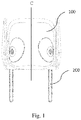
Fig. 1 is a front view of an automotive headrest according to the present invention; -
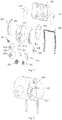
Fig. 2 is an exploded view of the automotive headrest according to the present invention; -
Fig. 3 is a part sectional view of the automotive headrest according to the present invention; -
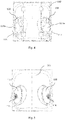
Fig. 4 is a rear view of a front cover board and speaker units according to the present invention; -
Fig. 5 is a view of the front cover board, the speaker units and the sound gathering cover according to the present invention; -
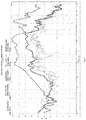
Fig. 6 is a test chart of the sound performance of the automotive headrest according to the present invention; - In the following, the preferable embodiments of the present invention are explained in detail combining with the accompanying drawings so that the advantages and features of the present invention can be easily understood by the skilled persons in the art. It is should be noted that the explanation on these implementations is to help understanding of the present invention, and is not intended to limit the present invention. Further, the technical features involved in the various embodiments of the present invention described below may be combined with each other as long as they do not conflict with each other.
- The orientation words mentioned in the present invention are defined by the conventional viewing angle of the headrest. For example, "left" and "right" correspond to the left side and the right side of the paper surface in
Fig. 1 , respectively, and "front" and "rear" are defined according to the traveling direction of an automobile. - The present embodiment provides an automotive seat comprising a backrest and an automotive headrest disposed on an upper portion of the backrest. Referring to
Figs. 1 - 5 , the automotive headrest comprises asupport 200 and aheadrest body 100 disposed on thesupport 200, and a lower portion of thesupport 200 is fixedly connected to the backrest, and an upper portion of thesupport 200 is fixedly connected to theheadrest body 100. Specifically as shown inFig. 2 , thesupport 200 is a rod of an inverted U shape, an upper end portion of thesupport 200 is located within theheadrest body 100, and two end portions of thesupport 200 extend out from a lower portion of theheadrest body 100, and the left and right lower end portions of thesupport 200 and theheadrest body 100 are seal fitted via aleft seal gasket 113 and aright seal gasket 114, respectively. - The headrest body is provided with a first cavity and a second cavity mutually independent, the first cavity and the second cavity are provided with a speaker unit respectively, the two speaker units are located on left and right sides of the headrest body respectively, and the speaker unit on the left side and the speaker unit on the right side are bilaterally symmetrical with respect to a central line of the headrest body in an up-down direction (shown by a straight line C in
Fig. 1 ). Due to that the first cavity and the second cavity are mutually independent, the two are not communicated with each other, and prevent the sound of the speaker units provided in the two cavities from rewinding, as shown inFig. 3 . In addition to the first cavity and the second cavity, the headrest body also has other cavities therein, and all cavities including the first cavity and the second cavity are filled with sound absorbing materials such as sound-absorbing cotton, thereby reducing the sound pressure level of the two sides and the back. - A structure of the headrest body and the speaker units is specifically as shown in
Fig. 2 . Thepillow body 100 comprises arear cover board 101 and afront cover board 102 that are connected with each other, and aleft cover board 105 and aright cover board 106 for closing therear cover board 101 and thefront cover board 102. Aleft partition board 103 is disposed between the left side portions of therear cover board 101 and thefront cover board 102 to form the independent first cavity between thefront cover board 102, theleft cover board 105 and theleft partition board 103; aright partition board 104 is disposed between the right side portions of therear cover board 101 and thefront cover board 102 to form the independent second cavity between thefront cover board 102, theright cover board 106 and theright partition board 104; the front and rear cavities are partitioned by theleft partition board 103 and theright partition board 104 to further reduce the sound pressure level of the back. The shapes of the left portion and the right portion of thefront cover board 102 are adapted to a left rear side and a right rear side of the head of an occupant respectively, specifically are arc-shaped, so that the left portion of thefront cover board 102 gradually extends forward from a middle part of thefront cover board 102 to a left edge thereof, and the right portion of thefront cover board 102 gradually extends forward from a middle part of thefront cover board 102 to a right edge thereof, that is, the left and right edges of thefront cover board 102 are slightly convex forward, and can block the sound of the speaker from propagating to the outside, and are more comfortable without blocking the viewing field at the same time. The left side portion and the right side portion of thefront cover board 102 have aleft mounting portion 117 and aright mounting portion 118 respectively, each of the speaker units comprises aspeaker left mounting portion 117 is provided with amounting hole 117a communicating with the first cavity, and theright mounting portion 118 are provided with aright mounting hole 118a communicating with the second cavity, and theleft speaker 115 is mounted within theleft mounting hole 117a, and theright speaker 116 is mounted within theright mounting hole 118a. As shown inFigs. 2 - 4 , theleft mounting portion 117 is further provided with aleft echo tube 119, which passes through theleft mounting portion 117 and extends rearwardly to communicate with the first cavity, and theright mounting portion 118 is further provided with aright echo tube 120, which passes through theright mounting portion 118 and extends rearwardly to communicate with the second cavity. Through theecho tubes - As shown in
Fig. 2 , the left speaker units further comprises aleft mesh cover 107, a leftsound gathering cover 109 and a leftspeaker cover board 111 sequentially provided on a front surface of theleft speaker 115; the right speaker units further comprises aright mesh cover 108, a rightsound gathering cover 110 and a rightspeaker cover board 112 sequentially provided on a front surface of theright speaker 116; wherein, the mesh covers are covered on the front surfaces of the speakers, positions on the sound gathering covers and the speaker cover boards corresponding to the mesh covers are provided with throughholes 121 for sound propagation respectively. As shown inFig. 5 , the sound gathering covers form a sound gathering structure, so that the sound emitted by theleft speaker 115 and theright speaker 116 is more directional. A center line of the throughhole 121 of theleft speaker unit 115 and a center line of the throughhole 121 of theleft speaker unit 116 forms an angle greater than 0 and less than 180 degrees with a traveling direction of an automobile respectively, in particular, both the angles on the two sides are 45 degrees. That is, the pointing angles of the speaker are positioned at 45 degrees. According to the suitable range of different kinds of human ear, the measurements are averaged. - In addition, the automotive headrest provided by the present embodiment has no DSP (digital signal processing) algorithm, and physical decompression and the control of the sound pressure level are achieved only through the design of the structure, thereby canceling out the sound and reducing the cost. The
left speaker 115 and theright speaker 116 are positioned as close as possible to the ear, and can also be assisted by other devices that gather sound close to the ear, such as sleeving a headset soft cover over the speakers. - It should also be noted that the connections between the components of the headrest body, between the components of the speakers, and between the headrest components and the speaker components employ detachably connection via hook components, and also may utilize other connection manners such as glue fixing.
- The automotive headrest provided by the present embodiment has the following advantages: the function of the private conversation can be realized only by the structural design, as shown in the performance test data in
FIG. 6 ; the cost is low, the development of the DSP algorithm is not required, and the sound pressure is reduced only by the physical method, the shape is simple and comfortable, and the function can be realized by only one headrest, and the material cost is low. - The embodiments described above are only for illustrating the technical concepts and features of the present invention, are preferred embodiments, and are intended to make those skilled in the art being able to understand the present invention and thereby implement it, and should not be concluded to limit the protective scope of this disclosure.
100 - headrest body; 200 - support; 101 - rear cover board; 102 - front cover board; 103 - left partition board; 104 - right partition board; 105 - left cover board; 106 - right cover board; 107 - left mesh cover; 108 - right mesh cover; 109 - left sound gathering cover; 110 - right sound gathering cover; 111 - left speaker cover board; 112 - right speaker cover board; 113 - left seal gasket; 114 - right seal gasket; 115 - left speaker; 116 - right speaker; 117 - left mounting portion; 117a - left mounting hole; 118 - right mounting portion; 118a - right mounting hole; 119 - left echo tube; 120 - right echo tube; 121 - through hole.
Claims (12)
- An automotive headrest, comprising a support and a headrest body disposed on the support, is characterized in that, the headrest body has a first cavity and a second cavity independent of one another, the first cavity and the second cavity are provided with a speaker unit respectively, and the two speaker units are located on left and right sides of the headrest body respectively.
- The automotive headrest according to claim 1, is characterized in that, the headrest body comprises a front cover board, a left side portion of the front cover board has a left mounting portion, and a right side portion of the front cover board has a right mounting portion, each of the speaker units respectively comprises a speaker, and the left mounting portion is provided with a left mounting hole communicating with the first cavity, the right mounting portion is provided with a right mounting hole communicating with the second cavity, and the speaker on the left side is mounted in the left mounting hole, and the speaker on the right side is mounted in the right mounting hole.
- The automotive headrest according to claim 2, is characterized in that, the left mounting portion is further provided with a left echo tube, which extends through the left mounting portion and extends rearward to communicate with the first cavity, and the right mounting portion is further provided with a right echo tube, which extends through the right mounting portion and extends rearward to communicate with the second cavity.
- The automotive headrest according to claim 2, is characterized in that, each of the speaker units further comprises a mesh cover, a sound gathering cover and a speaker cover board sequentially provided on a front surface of the speaker, the mesh cover is covered on the front surface of the speaker, positions on the sound gathering cover and the speaker cover board corresponding to the mesh cover are respectively provided with through holes for sound propagation.
- The automotive headrest according to claim 4, is characterized in that, a center line of the through hole of the speaker unit on the left side and a center line of the through hole of the speaker unit on the left side forms an angle greater than 0 and less than 180 degrees with a traveling direction of an automobile respectively.
- The automotive headrest according to claim 5, is characterized in that, both the angles are 45 degrees.
- The automotive headrest according to claim 4, is characterized in that, the speaker unit on the left side and the speaker unit on the right side are symmetrical.
- The automotive headrest according to claim 2, is characterized in that, the shapes of a left portion and a right portion of the front cover board are adapted to a left rear side and a right rear side of a head of an occupant respectively.
- The automotive headrest according to claim 8, is characterized in that, the left portion of the front cover board gradually extends forward from a middle part of the front cover board to a left edge thereof, and the right portion of the front cover board gradually extends forward from a middle part of the front cover board to a right edge thereof.
- The automotive headrest according to claim 1, is characterized in that, the first cavity and the second cavity are filled with a sound absorbing material.
- The automotive headrest according to claim 10, is characterized in that, the sound absorbing material is sound-absorbing cotton.
- An automotive seat, comprising a backrest, is characterized in that, it further comprises the automotive headrest according to any one of claims 1 - 11, and the automotive headrest is disposed on an upper portion of the backrest.
Applications Claiming Priority (2)
| Application Number | Priority Date | Filing Date | Title |
|---|---|---|---|
| CN201721450022.3U CN207328217U (en) | 2017-11-03 | 2017-11-03 | A kind of automotive headrest and automotive seat |
| PCT/CN2018/105488 WO2019085657A1 (en) | 2017-11-03 | 2018-09-13 | Automobile headrest and automobile seat |
Publications (3)
| Publication Number | Publication Date |
|---|---|
| EP3546285A1 true EP3546285A1 (en) | 2019-10-02 |
| EP3546285A4 EP3546285A4 (en) | 2020-04-01 |
| EP3546285B1 EP3546285B1 (en) | 2023-11-15 |
Family
ID=62364545
Family Applications (1)
| Application Number | Title | Priority Date | Filing Date |
|---|---|---|---|
| EP18873668.0A Active EP3546285B1 (en) | 2017-11-03 | 2018-09-13 | Automobile headrest and automobile seat |
Country Status (5)
| Country | Link |
|---|---|
| US (1) | US10960803B2 (en) |
| EP (1) | EP3546285B1 (en) |
| JP (1) | JP7008724B2 (en) |
| CN (1) | CN207328217U (en) |
| WO (1) | WO2019085657A1 (en) |
Families Citing this family (7)
| Publication number | Priority date | Publication date | Assignee | Title |
|---|---|---|---|---|
| CN207328217U (en) * | 2017-11-03 | 2018-05-08 | 苏州上声电子股份有限公司 | A kind of automotive headrest and automotive seat |
| CN110481401A (en) * | 2018-05-15 | 2019-11-22 | 中国船舶重工集团公司第七一一研究所 | Active noise reduction headrest |
| CN109159734A (en) * | 2018-09-20 | 2019-01-08 | 无锡吉兴汽车声学部件科技有限公司 | Automobile active noise reduction headrest |
| US11535136B2 (en) * | 2019-03-08 | 2022-12-27 | Harman International Industries, Incorporated | Headrest with integrated nose and loudspeaker enclosure |
| JP2021095037A (en) * | 2019-12-18 | 2021-06-24 | トヨタ自動車株式会社 | Vehicular seat and vehicular headrest |
| CN112677848B (en) * | 2021-01-08 | 2025-03-25 | 廊坊华安汽车装备有限公司 | Automobile seat headrest |
| CN113442810B (en) * | 2021-07-31 | 2022-10-11 | 重庆长安汽车股份有限公司 | Seat stereo headrest structure |
Family Cites Families (17)
| Publication number | Priority date | Publication date | Assignee | Title |
|---|---|---|---|---|
| US3512605A (en) * | 1967-08-31 | 1970-05-19 | David D Mccorkle | Stereo speaker headrest for an automobile seat |
| US3944020A (en) * | 1974-07-17 | 1976-03-16 | Ronald Leroy Brown | Speaker headrest for motor vehicles |
| US4638884A (en) * | 1985-07-11 | 1987-01-27 | Willis S. Cole | Chambered headrest mounting for stereophonic loudspeakers |
| JPS62193390U (en) * | 1986-05-30 | 1987-12-09 | ||
| JPH06245286A (en) * | 1993-02-19 | 1994-09-02 | Sony Corp | Speaker |
| US7899201B2 (en) | 2006-05-30 | 2011-03-01 | Polycom, Inc. | Speaker with acoustic damped port |
| JP5301194B2 (en) | 2008-04-01 | 2013-09-25 | トヨタ紡織株式会社 | Headrest |
| CN201895624U (en) * | 2010-11-12 | 2011-07-13 | 浙江吉利汽车研究院有限公司 | Novel automobile seat |
| JP6285165B2 (en) * | 2013-11-11 | 2018-02-28 | 株式会社デルタツーリング | Acoustic device and headrest |
| CN105745119B (en) * | 2013-11-19 | 2020-05-12 | 歌乐株式会社 | Headrest device and sound collecting device |
| EP3162622B1 (en) * | 2014-06-27 | 2019-04-24 | Clarion Co., Ltd. | Acoustic device |
| JP6440998B2 (en) * | 2014-08-25 | 2018-12-19 | 株式会社タチエス | Headrest and vehicle seat |
| WO2016117687A1 (en) * | 2015-01-23 | 2016-07-28 | 株式会社デルタツーリング | Method for manufacturing headrest, and headrest |
| US10271119B2 (en) * | 2015-02-14 | 2019-04-23 | Delta Tooling Co., Ltd. | Headrest having speaker |
| CN105835734B (en) * | 2016-03-19 | 2019-02-01 | 汉得利(常州)电子股份有限公司 | Novel on-vehicle vibration radiation headrest surround sound system |
| CN206141387U (en) | 2016-10-20 | 2017-05-03 | 比亚迪股份有限公司 | Automotive electronics headrest and car seat |
| CN207328217U (en) * | 2017-11-03 | 2018-05-08 | 苏州上声电子股份有限公司 | A kind of automotive headrest and automotive seat |
-
2017
- 2017-11-03 CN CN201721450022.3U patent/CN207328217U/en active Active
-
2018
- 2018-09-13 EP EP18873668.0A patent/EP3546285B1/en active Active
- 2018-09-13 JP JP2019554416A patent/JP7008724B2/en active Active
- 2018-09-13 US US16/483,268 patent/US10960803B2/en active Active
- 2018-09-13 WO PCT/CN2018/105488 patent/WO2019085657A1/en not_active Ceased
Also Published As
| Publication number | Publication date |
|---|---|
| WO2019085657A1 (en) | 2019-05-09 |
| CN207328217U (en) | 2018-05-08 |
| US10960803B2 (en) | 2021-03-30 |
| JP2020512236A (en) | 2020-04-23 |
| EP3546285A4 (en) | 2020-04-01 |
| EP3546285B1 (en) | 2023-11-15 |
| JP7008724B2 (en) | 2022-01-25 |
| US20200010002A1 (en) | 2020-01-09 |
Similar Documents
| Publication | Publication Date | Title |
|---|---|---|
| EP3546285A1 (en) | Automobile headrest and automobile seat | |
| KR102640919B1 (en) | Loudspeaker arrangement | |
| US20220266734A1 (en) | Vehicle Headrest | |
| JP4264068B2 (en) | Acoustic wave induction in vehicles | |
| JPS61131998A (en) | Acoustic device | |
| JP2009260524A (en) | Speaker system | |
| KR20000068694A (en) | Device including a built-in electroacoustic transducer for optimum speech reproduction | |
| JP2023027196A (en) | sound emitting device | |
| EP2840568A1 (en) | Acoustically active head rest | |
| US12225337B2 (en) | Near to the ear subwoofer | |
| US9967672B2 (en) | Audio system | |
| JP2002191469A (en) | Seat and headrest | |
| JPS6340091B2 (en) | ||
| WO2020080311A1 (en) | Acoustic output device | |
| JP2001095646A (en) | Headrest | |
| JP2004016711A (en) | Headrest with built-in speaker | |
| US20260067613A1 (en) | Sound reproducing device, acoustic system, and mobile device | |
| CN222080628U (en) | Car audio systems and cars | |
| KR200299113Y1 (en) | Speaker an addition seat | |
| CN206596166U (en) | The structure of the earphone | |
| JP6556257B2 (en) | Volume control device, volume control method, and program | |
| CN115179832A (en) | Automobile headrest and sound system | |
| KR830000934Y1 (en) | Speaker unit for in-vehicle | |
| JP2004168267A (en) | On-vehicle speaker device |
Legal Events
| Date | Code | Title | Description |
|---|---|---|---|
| STAA | Information on the status of an ep patent application or granted ep patent |
Free format text: STATUS: THE INTERNATIONAL PUBLICATION HAS BEEN MADE |
|
| PUAI | Public reference made under article 153(3) epc to a published international application that has entered the european phase |
Free format text: ORIGINAL CODE: 0009012 |
|
| STAA | Information on the status of an ep patent application or granted ep patent |
Free format text: STATUS: REQUEST FOR EXAMINATION WAS MADE |
|
| 17P | Request for examination filed |
Effective date: 20190613 |
|
| AK | Designated contracting states |
Kind code of ref document: A1 Designated state(s): AL AT BE BG CH CY CZ DE DK EE ES FI FR GB GR HR HU IE IS IT LI LT LU LV MC MK MT NL NO PL PT RO RS SE SI SK SM TR |
|
| AX | Request for extension of the european patent |
Extension state: BA ME |
|
| A4 | Supplementary search report drawn up and despatched |
Effective date: 20200228 |
|
| RIC1 | Information provided on ipc code assigned before grant |
Ipc: B60N 2/879 20180101AFI20200224BHEP |
|
| DAV | Request for validation of the european patent (deleted) | ||
| DAX | Request for extension of the european patent (deleted) | ||
| STAA | Information on the status of an ep patent application or granted ep patent |
Free format text: STATUS: EXAMINATION IS IN PROGRESS |
|
| 17Q | First examination report despatched |
Effective date: 20220316 |
|
| GRAP | Despatch of communication of intention to grant a patent |
Free format text: ORIGINAL CODE: EPIDOSNIGR1 |
|
| STAA | Information on the status of an ep patent application or granted ep patent |
Free format text: STATUS: GRANT OF PATENT IS INTENDED |
|
| GRAJ | Information related to disapproval of communication of intention to grant by the applicant or resumption of examination proceedings by the epo deleted |
Free format text: ORIGINAL CODE: EPIDOSDIGR1 |
|
| STAA | Information on the status of an ep patent application or granted ep patent |
Free format text: STATUS: EXAMINATION IS IN PROGRESS |
|
| INTG | Intention to grant announced |
Effective date: 20230704 |
|
| INTG | Intention to grant announced |
Effective date: 20230711 |
|
| GRAP | Despatch of communication of intention to grant a patent |
Free format text: ORIGINAL CODE: EPIDOSNIGR1 |
|
| STAA | Information on the status of an ep patent application or granted ep patent |
Free format text: STATUS: GRANT OF PATENT IS INTENDED |
|
| INTC | Intention to grant announced (deleted) | ||
| INTG | Intention to grant announced |
Effective date: 20230816 |
|
| GRAS | Grant fee paid |
Free format text: ORIGINAL CODE: EPIDOSNIGR3 |
|
| GRAA | (expected) grant |
Free format text: ORIGINAL CODE: 0009210 |
|
| STAA | Information on the status of an ep patent application or granted ep patent |
Free format text: STATUS: THE PATENT HAS BEEN GRANTED |
|
| AK | Designated contracting states |
Kind code of ref document: B1 Designated state(s): AL AT BE BG CH CY CZ DE DK EE ES FI FR GB GR HR HU IE IS IT LI LT LU LV MC MK MT NL NO PL PT RO RS SE SI SK SM TR |
|
| REG | Reference to a national code |
Ref country code: CH Ref legal event code: EP Ref country code: GB Ref legal event code: FG4D |
|
| REG | Reference to a national code |
Ref country code: DE Ref legal event code: R096 Ref document number: 602018061273 Country of ref document: DE |
|
| REG | Reference to a national code |
Ref country code: IE Ref legal event code: FG4D |
|
| REG | Reference to a national code |
Ref country code: LT Ref legal event code: MG9D |
|
| REG | Reference to a national code |
Ref country code: NL Ref legal event code: MP Effective date: 20231115 |
|
| PG25 | Lapsed in a contracting state [announced via postgrant information from national office to epo] |
Ref country code: GR Free format text: LAPSE BECAUSE OF FAILURE TO SUBMIT A TRANSLATION OF THE DESCRIPTION OR TO PAY THE FEE WITHIN THE PRESCRIBED TIME-LIMIT Effective date: 20240216 |
|
| PG25 | Lapsed in a contracting state [announced via postgrant information from national office to epo] |
Ref country code: IS Free format text: LAPSE BECAUSE OF FAILURE TO SUBMIT A TRANSLATION OF THE DESCRIPTION OR TO PAY THE FEE WITHIN THE PRESCRIBED TIME-LIMIT Effective date: 20240315 |
|
| PG25 | Lapsed in a contracting state [announced via postgrant information from national office to epo] |
Ref country code: LT Free format text: LAPSE BECAUSE OF FAILURE TO SUBMIT A TRANSLATION OF THE DESCRIPTION OR TO PAY THE FEE WITHIN THE PRESCRIBED TIME-LIMIT Effective date: 20231115 |
|
| REG | Reference to a national code |
Ref country code: AT Ref legal event code: MK05 Ref document number: 1631478 Country of ref document: AT Kind code of ref document: T Effective date: 20231115 |
|
| PG25 | Lapsed in a contracting state [announced via postgrant information from national office to epo] |
Ref country code: NL Free format text: LAPSE BECAUSE OF FAILURE TO SUBMIT A TRANSLATION OF THE DESCRIPTION OR TO PAY THE FEE WITHIN THE PRESCRIBED TIME-LIMIT Effective date: 20231115 |
|
| PG25 | Lapsed in a contracting state [announced via postgrant information from national office to epo] |
Ref country code: AT Free format text: LAPSE BECAUSE OF FAILURE TO SUBMIT A TRANSLATION OF THE DESCRIPTION OR TO PAY THE FEE WITHIN THE PRESCRIBED TIME-LIMIT Effective date: 20231115 |
|
| PG25 | Lapsed in a contracting state [announced via postgrant information from national office to epo] |
Ref country code: ES Free format text: LAPSE BECAUSE OF FAILURE TO SUBMIT A TRANSLATION OF THE DESCRIPTION OR TO PAY THE FEE WITHIN THE PRESCRIBED TIME-LIMIT Effective date: 20231115 |
|
| PG25 | Lapsed in a contracting state [announced via postgrant information from national office to epo] |
Ref country code: NL Free format text: LAPSE BECAUSE OF FAILURE TO SUBMIT A TRANSLATION OF THE DESCRIPTION OR TO PAY THE FEE WITHIN THE PRESCRIBED TIME-LIMIT Effective date: 20231115 Ref country code: LT Free format text: LAPSE BECAUSE OF FAILURE TO SUBMIT A TRANSLATION OF THE DESCRIPTION OR TO PAY THE FEE WITHIN THE PRESCRIBED TIME-LIMIT Effective date: 20231115 Ref country code: IS Free format text: LAPSE BECAUSE OF FAILURE TO SUBMIT A TRANSLATION OF THE DESCRIPTION OR TO PAY THE FEE WITHIN THE PRESCRIBED TIME-LIMIT Effective date: 20240315 Ref country code: GR Free format text: LAPSE BECAUSE OF FAILURE TO SUBMIT A TRANSLATION OF THE DESCRIPTION OR TO PAY THE FEE WITHIN THE PRESCRIBED TIME-LIMIT Effective date: 20240216 Ref country code: ES Free format text: LAPSE BECAUSE OF FAILURE TO SUBMIT A TRANSLATION OF THE DESCRIPTION OR TO PAY THE FEE WITHIN THE PRESCRIBED TIME-LIMIT Effective date: 20231115 Ref country code: BG Free format text: LAPSE BECAUSE OF FAILURE TO SUBMIT A TRANSLATION OF THE DESCRIPTION OR TO PAY THE FEE WITHIN THE PRESCRIBED TIME-LIMIT Effective date: 20240215 Ref country code: AT Free format text: LAPSE BECAUSE OF FAILURE TO SUBMIT A TRANSLATION OF THE DESCRIPTION OR TO PAY THE FEE WITHIN THE PRESCRIBED TIME-LIMIT Effective date: 20231115 Ref country code: PT Free format text: LAPSE BECAUSE OF FAILURE TO SUBMIT A TRANSLATION OF THE DESCRIPTION OR TO PAY THE FEE WITHIN THE PRESCRIBED TIME-LIMIT Effective date: 20240315 |
|
| PG25 | Lapsed in a contracting state [announced via postgrant information from national office to epo] |
Ref country code: SE Free format text: LAPSE BECAUSE OF FAILURE TO SUBMIT A TRANSLATION OF THE DESCRIPTION OR TO PAY THE FEE WITHIN THE PRESCRIBED TIME-LIMIT Effective date: 20231115 Ref country code: RS Free format text: LAPSE BECAUSE OF FAILURE TO SUBMIT A TRANSLATION OF THE DESCRIPTION OR TO PAY THE FEE WITHIN THE PRESCRIBED TIME-LIMIT Effective date: 20231115 Ref country code: PL Free format text: LAPSE BECAUSE OF FAILURE TO SUBMIT A TRANSLATION OF THE DESCRIPTION OR TO PAY THE FEE WITHIN THE PRESCRIBED TIME-LIMIT Effective date: 20231115 Ref country code: NO Free format text: LAPSE BECAUSE OF FAILURE TO SUBMIT A TRANSLATION OF THE DESCRIPTION OR TO PAY THE FEE WITHIN THE PRESCRIBED TIME-LIMIT Effective date: 20240215 Ref country code: LV Free format text: LAPSE BECAUSE OF FAILURE TO SUBMIT A TRANSLATION OF THE DESCRIPTION OR TO PAY THE FEE WITHIN THE PRESCRIBED TIME-LIMIT Effective date: 20231115 Ref country code: HR Free format text: LAPSE BECAUSE OF FAILURE TO SUBMIT A TRANSLATION OF THE DESCRIPTION OR TO PAY THE FEE WITHIN THE PRESCRIBED TIME-LIMIT Effective date: 20231115 |
|
| PG25 | Lapsed in a contracting state [announced via postgrant information from national office to epo] |
Ref country code: DK Free format text: LAPSE BECAUSE OF FAILURE TO SUBMIT A TRANSLATION OF THE DESCRIPTION OR TO PAY THE FEE WITHIN THE PRESCRIBED TIME-LIMIT Effective date: 20231115 |
|
| PG25 | Lapsed in a contracting state [announced via postgrant information from national office to epo] |
Ref country code: CZ Free format text: LAPSE BECAUSE OF FAILURE TO SUBMIT A TRANSLATION OF THE DESCRIPTION OR TO PAY THE FEE WITHIN THE PRESCRIBED TIME-LIMIT Effective date: 20231115 |
|
| PG25 | Lapsed in a contracting state [announced via postgrant information from national office to epo] |
Ref country code: SK Free format text: LAPSE BECAUSE OF FAILURE TO SUBMIT A TRANSLATION OF THE DESCRIPTION OR TO PAY THE FEE WITHIN THE PRESCRIBED TIME-LIMIT Effective date: 20231115 |
|
| PG25 | Lapsed in a contracting state [announced via postgrant information from national office to epo] |
Ref country code: SM Free format text: LAPSE BECAUSE OF FAILURE TO SUBMIT A TRANSLATION OF THE DESCRIPTION OR TO PAY THE FEE WITHIN THE PRESCRIBED TIME-LIMIT Effective date: 20231115 Ref country code: SK Free format text: LAPSE BECAUSE OF FAILURE TO SUBMIT A TRANSLATION OF THE DESCRIPTION OR TO PAY THE FEE WITHIN THE PRESCRIBED TIME-LIMIT Effective date: 20231115 Ref country code: RO Free format text: LAPSE BECAUSE OF FAILURE TO SUBMIT A TRANSLATION OF THE DESCRIPTION OR TO PAY THE FEE WITHIN THE PRESCRIBED TIME-LIMIT Effective date: 20231115 Ref country code: EE Free format text: LAPSE BECAUSE OF FAILURE TO SUBMIT A TRANSLATION OF THE DESCRIPTION OR TO PAY THE FEE WITHIN THE PRESCRIBED TIME-LIMIT Effective date: 20231115 Ref country code: DK Free format text: LAPSE BECAUSE OF FAILURE TO SUBMIT A TRANSLATION OF THE DESCRIPTION OR TO PAY THE FEE WITHIN THE PRESCRIBED TIME-LIMIT Effective date: 20231115 Ref country code: CZ Free format text: LAPSE BECAUSE OF FAILURE TO SUBMIT A TRANSLATION OF THE DESCRIPTION OR TO PAY THE FEE WITHIN THE PRESCRIBED TIME-LIMIT Effective date: 20231115 |
|
| REG | Reference to a national code |
Ref country code: DE Ref legal event code: R097 Ref document number: 602018061273 Country of ref document: DE |
|
| PLBE | No opposition filed within time limit |
Free format text: ORIGINAL CODE: 0009261 |
|
| STAA | Information on the status of an ep patent application or granted ep patent |
Free format text: STATUS: NO OPPOSITION FILED WITHIN TIME LIMIT |
|
| 26N | No opposition filed |
Effective date: 20240819 |
|
| PG25 | Lapsed in a contracting state [announced via postgrant information from national office to epo] |
Ref country code: SI Free format text: LAPSE BECAUSE OF FAILURE TO SUBMIT A TRANSLATION OF THE DESCRIPTION OR TO PAY THE FEE WITHIN THE PRESCRIBED TIME-LIMIT Effective date: 20231115 |
|
| PG25 | Lapsed in a contracting state [announced via postgrant information from national office to epo] |
Ref country code: SI Free format text: LAPSE BECAUSE OF FAILURE TO SUBMIT A TRANSLATION OF THE DESCRIPTION OR TO PAY THE FEE WITHIN THE PRESCRIBED TIME-LIMIT Effective date: 20231115 |
|
| PG25 | Lapsed in a contracting state [announced via postgrant information from national office to epo] |
Ref country code: MC Free format text: LAPSE BECAUSE OF FAILURE TO SUBMIT A TRANSLATION OF THE DESCRIPTION OR TO PAY THE FEE WITHIN THE PRESCRIBED TIME-LIMIT Effective date: 20231115 |
|
| REG | Reference to a national code |
Ref country code: CH Ref legal event code: PL |
|
| PG25 | Lapsed in a contracting state [announced via postgrant information from national office to epo] |
Ref country code: LU Free format text: LAPSE BECAUSE OF NON-PAYMENT OF DUE FEES Effective date: 20240913 |
|
| GBPC | Gb: european patent ceased through non-payment of renewal fee |
Effective date: 20240913 |
|
| PG25 | Lapsed in a contracting state [announced via postgrant information from national office to epo] |
Ref country code: GB Free format text: LAPSE BECAUSE OF NON-PAYMENT OF DUE FEES Effective date: 20240913 |
|
| REG | Reference to a national code |
Ref country code: BE Ref legal event code: MM Effective date: 20240930 |
|
| PG25 | Lapsed in a contracting state [announced via postgrant information from national office to epo] |
Ref country code: BE Free format text: LAPSE BECAUSE OF NON-PAYMENT OF DUE FEES Effective date: 20240930 |
|
| PG25 | Lapsed in a contracting state [announced via postgrant information from national office to epo] |
Ref country code: CH Free format text: LAPSE BECAUSE OF NON-PAYMENT OF DUE FEES Effective date: 20240930 |
|
| PG25 | Lapsed in a contracting state [announced via postgrant information from national office to epo] |
Ref country code: IE Free format text: LAPSE BECAUSE OF NON-PAYMENT OF DUE FEES Effective date: 20240913 |
|
| PG25 | Lapsed in a contracting state [announced via postgrant information from national office to epo] |
Ref country code: FI Free format text: LAPSE BECAUSE OF FAILURE TO SUBMIT A TRANSLATION OF THE DESCRIPTION OR TO PAY THE FEE WITHIN THE PRESCRIBED TIME-LIMIT Effective date: 20231115 |
|
| PGFP | Annual fee paid to national office [announced via postgrant information from national office to epo] |
Ref country code: IT Payment date: 20250923 Year of fee payment: 8 |
|
| PGFP | Annual fee paid to national office [announced via postgrant information from national office to epo] |
Ref country code: FR Payment date: 20250929 Year of fee payment: 8 |
|
| PGFP | Annual fee paid to national office [announced via postgrant information from national office to epo] |
Ref country code: DE Payment date: 20250929 Year of fee payment: 8 |
|
| PG25 | Lapsed in a contracting state [announced via postgrant information from national office to epo] |
Ref country code: CY Free format text: LAPSE BECAUSE OF FAILURE TO SUBMIT A TRANSLATION OF THE DESCRIPTION OR TO PAY THE FEE WITHIN THE PRESCRIBED TIME-LIMIT; INVALID AB INITIO Effective date: 20180913 |
|
| PG25 | Lapsed in a contracting state [announced via postgrant information from national office to epo] |
Ref country code: HU Free format text: LAPSE BECAUSE OF FAILURE TO SUBMIT A TRANSLATION OF THE DESCRIPTION OR TO PAY THE FEE WITHIN THE PRESCRIBED TIME-LIMIT; INVALID AB INITIO Effective date: 20180913 |