EP3546274A1 - Vehicle, vehicle slope assist system, and control method thereof - Google Patents
Vehicle, vehicle slope assist system, and control method thereof Download PDFInfo
- Publication number
- EP3546274A1 EP3546274A1 EP17874203.7A EP17874203A EP3546274A1 EP 3546274 A1 EP3546274 A1 EP 3546274A1 EP 17874203 A EP17874203 A EP 17874203A EP 3546274 A1 EP3546274 A1 EP 3546274A1
- Authority
- EP
- European Patent Office
- Prior art keywords
- vehicle
- auxiliary system
- ramp
- ramp auxiliary
- torque
- Prior art date
- Legal status (The legal status is an assumption and is not a legal conclusion. Google has not performed a legal analysis and makes no representation as to the accuracy of the status listed.)
- Withdrawn
Links
- 238000000034 method Methods 0.000 title claims abstract description 39
- 230000004913 activation Effects 0.000 claims abstract description 65
- 230000003213 activating effect Effects 0.000 claims abstract description 15
- 238000010586 diagram Methods 0.000 description 9
- 230000008569 process Effects 0.000 description 4
- 238000004891 communication Methods 0.000 description 2
- 238000005516 engineering process Methods 0.000 description 2
- 230000005484 gravity Effects 0.000 description 2
- 230000008094 contradictory effect Effects 0.000 description 1
- 230000010354 integration Effects 0.000 description 1
- 238000012986 modification Methods 0.000 description 1
- 230000004048 modification Effects 0.000 description 1
Images


Classifications
-
- B—PERFORMING OPERATIONS; TRANSPORTING
- B60—VEHICLES IN GENERAL
- B60L—PROPULSION OF ELECTRICALLY-PROPELLED VEHICLES; SUPPLYING ELECTRIC POWER FOR AUXILIARY EQUIPMENT OF ELECTRICALLY-PROPELLED VEHICLES; ELECTRODYNAMIC BRAKE SYSTEMS FOR VEHICLES IN GENERAL; MAGNETIC SUSPENSION OR LEVITATION FOR VEHICLES; MONITORING OPERATING VARIABLES OF ELECTRICALLY-PROPELLED VEHICLES; ELECTRIC SAFETY DEVICES FOR ELECTRICALLY-PROPELLED VEHICLES
- B60L15/00—Methods, circuits, or devices for controlling the traction-motor speed of electrically-propelled vehicles
- B60L15/20—Methods, circuits, or devices for controlling the traction-motor speed of electrically-propelled vehicles for control of the vehicle or its driving motor to achieve a desired performance, e.g. speed, torque, programmed variation of speed
- B60L15/2072—Methods, circuits, or devices for controlling the traction-motor speed of electrically-propelled vehicles for control of the vehicle or its driving motor to achieve a desired performance, e.g. speed, torque, programmed variation of speed for drive off
- B60L15/2081—Methods, circuits, or devices for controlling the traction-motor speed of electrically-propelled vehicles for control of the vehicle or its driving motor to achieve a desired performance, e.g. speed, torque, programmed variation of speed for drive off for drive off on a slope
-
- B—PERFORMING OPERATIONS; TRANSPORTING
- B60—VEHICLES IN GENERAL
- B60L—PROPULSION OF ELECTRICALLY-PROPELLED VEHICLES; SUPPLYING ELECTRIC POWER FOR AUXILIARY EQUIPMENT OF ELECTRICALLY-PROPELLED VEHICLES; ELECTRODYNAMIC BRAKE SYSTEMS FOR VEHICLES IN GENERAL; MAGNETIC SUSPENSION OR LEVITATION FOR VEHICLES; MONITORING OPERATING VARIABLES OF ELECTRICALLY-PROPELLED VEHICLES; ELECTRIC SAFETY DEVICES FOR ELECTRICALLY-PROPELLED VEHICLES
- B60L15/00—Methods, circuits, or devices for controlling the traction-motor speed of electrically-propelled vehicles
- B60L15/20—Methods, circuits, or devices for controlling the traction-motor speed of electrically-propelled vehicles for control of the vehicle or its driving motor to achieve a desired performance, e.g. speed, torque, programmed variation of speed
- B60L15/2009—Methods, circuits, or devices for controlling the traction-motor speed of electrically-propelled vehicles for control of the vehicle or its driving motor to achieve a desired performance, e.g. speed, torque, programmed variation of speed for braking
- B60L15/2018—Methods, circuits, or devices for controlling the traction-motor speed of electrically-propelled vehicles for control of the vehicle or its driving motor to achieve a desired performance, e.g. speed, torque, programmed variation of speed for braking for braking on a slope
-
- B—PERFORMING OPERATIONS; TRANSPORTING
- B60—VEHICLES IN GENERAL
- B60L—PROPULSION OF ELECTRICALLY-PROPELLED VEHICLES; SUPPLYING ELECTRIC POWER FOR AUXILIARY EQUIPMENT OF ELECTRICALLY-PROPELLED VEHICLES; ELECTRODYNAMIC BRAKE SYSTEMS FOR VEHICLES IN GENERAL; MAGNETIC SUSPENSION OR LEVITATION FOR VEHICLES; MONITORING OPERATING VARIABLES OF ELECTRICALLY-PROPELLED VEHICLES; ELECTRIC SAFETY DEVICES FOR ELECTRICALLY-PROPELLED VEHICLES
- B60L2220/00—Electrical machine types; Structures or applications thereof
- B60L2220/40—Electrical machine applications
- B60L2220/42—Electrical machine applications with use of more than one motor
-
- B—PERFORMING OPERATIONS; TRANSPORTING
- B60—VEHICLES IN GENERAL
- B60L—PROPULSION OF ELECTRICALLY-PROPELLED VEHICLES; SUPPLYING ELECTRIC POWER FOR AUXILIARY EQUIPMENT OF ELECTRICALLY-PROPELLED VEHICLES; ELECTRODYNAMIC BRAKE SYSTEMS FOR VEHICLES IN GENERAL; MAGNETIC SUSPENSION OR LEVITATION FOR VEHICLES; MONITORING OPERATING VARIABLES OF ELECTRICALLY-PROPELLED VEHICLES; ELECTRIC SAFETY DEVICES FOR ELECTRICALLY-PROPELLED VEHICLES
- B60L2220/00—Electrical machine types; Structures or applications thereof
- B60L2220/40—Electrical machine applications
- B60L2220/44—Wheel Hub motors, i.e. integrated in the wheel hub
-
- B—PERFORMING OPERATIONS; TRANSPORTING
- B60—VEHICLES IN GENERAL
- B60L—PROPULSION OF ELECTRICALLY-PROPELLED VEHICLES; SUPPLYING ELECTRIC POWER FOR AUXILIARY EQUIPMENT OF ELECTRICALLY-PROPELLED VEHICLES; ELECTRODYNAMIC BRAKE SYSTEMS FOR VEHICLES IN GENERAL; MAGNETIC SUSPENSION OR LEVITATION FOR VEHICLES; MONITORING OPERATING VARIABLES OF ELECTRICALLY-PROPELLED VEHICLES; ELECTRIC SAFETY DEVICES FOR ELECTRICALLY-PROPELLED VEHICLES
- B60L2220/00—Electrical machine types; Structures or applications thereof
- B60L2220/40—Electrical machine applications
- B60L2220/46—Wheel motors, i.e. motor connected to only one wheel
-
- B—PERFORMING OPERATIONS; TRANSPORTING
- B60—VEHICLES IN GENERAL
- B60L—PROPULSION OF ELECTRICALLY-PROPELLED VEHICLES; SUPPLYING ELECTRIC POWER FOR AUXILIARY EQUIPMENT OF ELECTRICALLY-PROPELLED VEHICLES; ELECTRODYNAMIC BRAKE SYSTEMS FOR VEHICLES IN GENERAL; MAGNETIC SUSPENSION OR LEVITATION FOR VEHICLES; MONITORING OPERATING VARIABLES OF ELECTRICALLY-PROPELLED VEHICLES; ELECTRIC SAFETY DEVICES FOR ELECTRICALLY-PROPELLED VEHICLES
- B60L2240/00—Control parameters of input or output; Target parameters
- B60L2240/10—Vehicle control parameters
- B60L2240/12—Speed
-
- B—PERFORMING OPERATIONS; TRANSPORTING
- B60—VEHICLES IN GENERAL
- B60L—PROPULSION OF ELECTRICALLY-PROPELLED VEHICLES; SUPPLYING ELECTRIC POWER FOR AUXILIARY EQUIPMENT OF ELECTRICALLY-PROPELLED VEHICLES; ELECTRODYNAMIC BRAKE SYSTEMS FOR VEHICLES IN GENERAL; MAGNETIC SUSPENSION OR LEVITATION FOR VEHICLES; MONITORING OPERATING VARIABLES OF ELECTRICALLY-PROPELLED VEHICLES; ELECTRIC SAFETY DEVICES FOR ELECTRICALLY-PROPELLED VEHICLES
- B60L2240/00—Control parameters of input or output; Target parameters
- B60L2240/40—Drive Train control parameters
- B60L2240/42—Drive Train control parameters related to electric machines
- B60L2240/421—Speed
-
- B—PERFORMING OPERATIONS; TRANSPORTING
- B60—VEHICLES IN GENERAL
- B60L—PROPULSION OF ELECTRICALLY-PROPELLED VEHICLES; SUPPLYING ELECTRIC POWER FOR AUXILIARY EQUIPMENT OF ELECTRICALLY-PROPELLED VEHICLES; ELECTRODYNAMIC BRAKE SYSTEMS FOR VEHICLES IN GENERAL; MAGNETIC SUSPENSION OR LEVITATION FOR VEHICLES; MONITORING OPERATING VARIABLES OF ELECTRICALLY-PROPELLED VEHICLES; ELECTRIC SAFETY DEVICES FOR ELECTRICALLY-PROPELLED VEHICLES
- B60L2240/00—Control parameters of input or output; Target parameters
- B60L2240/40—Drive Train control parameters
- B60L2240/42—Drive Train control parameters related to electric machines
- B60L2240/423—Torque
-
- B—PERFORMING OPERATIONS; TRANSPORTING
- B60—VEHICLES IN GENERAL
- B60L—PROPULSION OF ELECTRICALLY-PROPELLED VEHICLES; SUPPLYING ELECTRIC POWER FOR AUXILIARY EQUIPMENT OF ELECTRICALLY-PROPELLED VEHICLES; ELECTRODYNAMIC BRAKE SYSTEMS FOR VEHICLES IN GENERAL; MAGNETIC SUSPENSION OR LEVITATION FOR VEHICLES; MONITORING OPERATING VARIABLES OF ELECTRICALLY-PROPELLED VEHICLES; ELECTRIC SAFETY DEVICES FOR ELECTRICALLY-PROPELLED VEHICLES
- B60L2240/00—Control parameters of input or output; Target parameters
- B60L2240/40—Drive Train control parameters
- B60L2240/46—Drive Train control parameters related to wheels
- B60L2240/461—Speed
-
- B—PERFORMING OPERATIONS; TRANSPORTING
- B60—VEHICLES IN GENERAL
- B60L—PROPULSION OF ELECTRICALLY-PROPELLED VEHICLES; SUPPLYING ELECTRIC POWER FOR AUXILIARY EQUIPMENT OF ELECTRICALLY-PROPELLED VEHICLES; ELECTRODYNAMIC BRAKE SYSTEMS FOR VEHICLES IN GENERAL; MAGNETIC SUSPENSION OR LEVITATION FOR VEHICLES; MONITORING OPERATING VARIABLES OF ELECTRICALLY-PROPELLED VEHICLES; ELECTRIC SAFETY DEVICES FOR ELECTRICALLY-PROPELLED VEHICLES
- B60L2240/00—Control parameters of input or output; Target parameters
- B60L2240/40—Drive Train control parameters
- B60L2240/46—Drive Train control parameters related to wheels
- B60L2240/463—Torque
-
- B—PERFORMING OPERATIONS; TRANSPORTING
- B60—VEHICLES IN GENERAL
- B60L—PROPULSION OF ELECTRICALLY-PROPELLED VEHICLES; SUPPLYING ELECTRIC POWER FOR AUXILIARY EQUIPMENT OF ELECTRICALLY-PROPELLED VEHICLES; ELECTRODYNAMIC BRAKE SYSTEMS FOR VEHICLES IN GENERAL; MAGNETIC SUSPENSION OR LEVITATION FOR VEHICLES; MONITORING OPERATING VARIABLES OF ELECTRICALLY-PROPELLED VEHICLES; ELECTRIC SAFETY DEVICES FOR ELECTRICALLY-PROPELLED VEHICLES
- B60L2240/00—Control parameters of input or output; Target parameters
- B60L2240/40—Drive Train control parameters
- B60L2240/46—Drive Train control parameters related to wheels
- B60L2240/465—Slip
-
- B—PERFORMING OPERATIONS; TRANSPORTING
- B60—VEHICLES IN GENERAL
- B60L—PROPULSION OF ELECTRICALLY-PROPELLED VEHICLES; SUPPLYING ELECTRIC POWER FOR AUXILIARY EQUIPMENT OF ELECTRICALLY-PROPELLED VEHICLES; ELECTRODYNAMIC BRAKE SYSTEMS FOR VEHICLES IN GENERAL; MAGNETIC SUSPENSION OR LEVITATION FOR VEHICLES; MONITORING OPERATING VARIABLES OF ELECTRICALLY-PROPELLED VEHICLES; ELECTRIC SAFETY DEVICES FOR ELECTRICALLY-PROPELLED VEHICLES
- B60L2240/00—Control parameters of input or output; Target parameters
- B60L2240/40—Drive Train control parameters
- B60L2240/48—Drive Train control parameters related to transmissions
-
- B—PERFORMING OPERATIONS; TRANSPORTING
- B60—VEHICLES IN GENERAL
- B60L—PROPULSION OF ELECTRICALLY-PROPELLED VEHICLES; SUPPLYING ELECTRIC POWER FOR AUXILIARY EQUIPMENT OF ELECTRICALLY-PROPELLED VEHICLES; ELECTRODYNAMIC BRAKE SYSTEMS FOR VEHICLES IN GENERAL; MAGNETIC SUSPENSION OR LEVITATION FOR VEHICLES; MONITORING OPERATING VARIABLES OF ELECTRICALLY-PROPELLED VEHICLES; ELECTRIC SAFETY DEVICES FOR ELECTRICALLY-PROPELLED VEHICLES
- B60L2240/00—Control parameters of input or output; Target parameters
- B60L2240/60—Navigation input
- B60L2240/62—Vehicle position
-
- B—PERFORMING OPERATIONS; TRANSPORTING
- B60—VEHICLES IN GENERAL
- B60L—PROPULSION OF ELECTRICALLY-PROPELLED VEHICLES; SUPPLYING ELECTRIC POWER FOR AUXILIARY EQUIPMENT OF ELECTRICALLY-PROPELLED VEHICLES; ELECTRODYNAMIC BRAKE SYSTEMS FOR VEHICLES IN GENERAL; MAGNETIC SUSPENSION OR LEVITATION FOR VEHICLES; MONITORING OPERATING VARIABLES OF ELECTRICALLY-PROPELLED VEHICLES; ELECTRIC SAFETY DEVICES FOR ELECTRICALLY-PROPELLED VEHICLES
- B60L2240/00—Control parameters of input or output; Target parameters
- B60L2240/60—Navigation input
- B60L2240/64—Road conditions
- B60L2240/642—Slope of road
-
- B—PERFORMING OPERATIONS; TRANSPORTING
- B60—VEHICLES IN GENERAL
- B60L—PROPULSION OF ELECTRICALLY-PROPELLED VEHICLES; SUPPLYING ELECTRIC POWER FOR AUXILIARY EQUIPMENT OF ELECTRICALLY-PROPELLED VEHICLES; ELECTRODYNAMIC BRAKE SYSTEMS FOR VEHICLES IN GENERAL; MAGNETIC SUSPENSION OR LEVITATION FOR VEHICLES; MONITORING OPERATING VARIABLES OF ELECTRICALLY-PROPELLED VEHICLES; ELECTRIC SAFETY DEVICES FOR ELECTRICALLY-PROPELLED VEHICLES
- B60L2250/00—Driver interactions
- B60L2250/26—Driver interactions by pedal actuation
-
- B—PERFORMING OPERATIONS; TRANSPORTING
- B60—VEHICLES IN GENERAL
- B60L—PROPULSION OF ELECTRICALLY-PROPELLED VEHICLES; SUPPLYING ELECTRIC POWER FOR AUXILIARY EQUIPMENT OF ELECTRICALLY-PROPELLED VEHICLES; ELECTRODYNAMIC BRAKE SYSTEMS FOR VEHICLES IN GENERAL; MAGNETIC SUSPENSION OR LEVITATION FOR VEHICLES; MONITORING OPERATING VARIABLES OF ELECTRICALLY-PROPELLED VEHICLES; ELECTRIC SAFETY DEVICES FOR ELECTRICALLY-PROPELLED VEHICLES
- B60L2260/00—Operating Modes
- B60L2260/20—Drive modes; Transition between modes
- B60L2260/22—Standstill, e.g. zero speed
-
- B—PERFORMING OPERATIONS; TRANSPORTING
- B60—VEHICLES IN GENERAL
- B60L—PROPULSION OF ELECTRICALLY-PROPELLED VEHICLES; SUPPLYING ELECTRIC POWER FOR AUXILIARY EQUIPMENT OF ELECTRICALLY-PROPELLED VEHICLES; ELECTRODYNAMIC BRAKE SYSTEMS FOR VEHICLES IN GENERAL; MAGNETIC SUSPENSION OR LEVITATION FOR VEHICLES; MONITORING OPERATING VARIABLES OF ELECTRICALLY-PROPELLED VEHICLES; ELECTRIC SAFETY DEVICES FOR ELECTRICALLY-PROPELLED VEHICLES
- B60L2260/00—Operating Modes
- B60L2260/20—Drive modes; Transition between modes
- B60L2260/26—Transition between different drive modes
-
- Y—GENERAL TAGGING OF NEW TECHNOLOGICAL DEVELOPMENTS; GENERAL TAGGING OF CROSS-SECTIONAL TECHNOLOGIES SPANNING OVER SEVERAL SECTIONS OF THE IPC; TECHNICAL SUBJECTS COVERED BY FORMER USPC CROSS-REFERENCE ART COLLECTIONS [XRACs] AND DIGESTS
- Y02—TECHNOLOGIES OR APPLICATIONS FOR MITIGATION OR ADAPTATION AGAINST CLIMATE CHANGE
- Y02T—CLIMATE CHANGE MITIGATION TECHNOLOGIES RELATED TO TRANSPORTATION
- Y02T10/00—Road transport of goods or passengers
- Y02T10/60—Other road transportation technologies with climate change mitigation effect
- Y02T10/64—Electric machine technologies in electromobility
-
- Y—GENERAL TAGGING OF NEW TECHNOLOGICAL DEVELOPMENTS; GENERAL TAGGING OF CROSS-SECTIONAL TECHNOLOGIES SPANNING OVER SEVERAL SECTIONS OF THE IPC; TECHNICAL SUBJECTS COVERED BY FORMER USPC CROSS-REFERENCE ART COLLECTIONS [XRACs] AND DIGESTS
- Y02—TECHNOLOGIES OR APPLICATIONS FOR MITIGATION OR ADAPTATION AGAINST CLIMATE CHANGE
- Y02T—CLIMATE CHANGE MITIGATION TECHNOLOGIES RELATED TO TRANSPORTATION
- Y02T10/00—Road transport of goods or passengers
- Y02T10/60—Other road transportation technologies with climate change mitigation effect
- Y02T10/72—Electric energy management in electromobility
-
- Y—GENERAL TAGGING OF NEW TECHNOLOGICAL DEVELOPMENTS; GENERAL TAGGING OF CROSS-SECTIONAL TECHNOLOGIES SPANNING OVER SEVERAL SECTIONS OF THE IPC; TECHNICAL SUBJECTS COVERED BY FORMER USPC CROSS-REFERENCE ART COLLECTIONS [XRACs] AND DIGESTS
- Y02—TECHNOLOGIES OR APPLICATIONS FOR MITIGATION OR ADAPTATION AGAINST CLIMATE CHANGE
- Y02T—CLIMATE CHANGE MITIGATION TECHNOLOGIES RELATED TO TRANSPORTATION
- Y02T90/00—Enabling technologies or technologies with a potential or indirect contribution to GHG emissions mitigation
- Y02T90/10—Technologies relating to charging of electric vehicles
- Y02T90/16—Information or communication technologies improving the operation of electric vehicles
Definitions
- This application relates to the technical field of vehicles and particularly relates to a control method of a ramp auxiliary system of a vehicle, a ramp auxiliary system of a vehicle, and a vehicle.
- This application aims to solve at least one of the technical problems in the above technology to some extent. Therefore, this application is directed to a control method of a ramp auxiliary system of a vehicle, and the control method can accurately and comprehensively judge the running state of the vehicle in advance and can automatically drive the vehicle in time to prevent the vehicle from slipping, thereby improving the safety of the vehicle.
- This application is also directed to a ramp auxiliary system of a vehicle.
- This application is further directed to a vehicle.
- a first embodiment of this application provides a control method of a ramp auxiliary system of a vehicle, wherein the vehicle is driven by a rim motor.
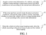
- the method includes: acquiring current state information of the vehicle; judging whether the ramp auxiliary system meets preset activation conditions or not according to the current state information, wherein the preset activation conditions are used for activating the ramp auxiliary system; activating the ramp auxiliary system if the ramp auxiliary system meets the preset activation conditions; judging whether to control the vehicle to be in a torque keeping mode or not according to the current state information, wherein the torque for driving the vehicle is kept unchanged in the torque keeping mode; and when the vehicle is in the torque keeping mode, driving the vehicle according to the preset torque to prevent the vehicle from slipping.
- the control method of the ramp auxiliary system of the vehicle includes: when the ramp auxiliary system meets the preset activation conditions, activating the ramp auxiliary system; judging whether to control the vehicle to be in the torque keeping mode or not according to the current state information of the vehicle; and when the vehicle is in the torque keeping mode, driving the vehicle according to the preset torque to prevent the vehicle from slipping. Therefore, the running state of the vehicle can be accurately and comprehensively judged in advance, and driving control can be automatically performed on the vehicle in time to prevent the vehicle from slipping, thereby improving the safety of the vehicle.
- a second embodiment of this application provides a ramp auxiliary system of a vehicle, wherein the vehicle is driven by a rim motor.
- the system includes an acquisition module which is used for acquiring current state information of the vehicle; a judgment module which is used for judging whether the ramp auxiliary system meets preset activation conditions or not according to the current state information, wherein the preset activation conditions are used for activating the ramp auxiliary system; an activation module which is used for activating the ramp auxiliary system when the ramp auxiliary system meets the preset activation conditions; and a control module which is used for judging whether to control the vehicle to be in a torque keeping mode or not according to the current state information when the ramp auxiliary system is activated, and driving the vehicle according to preset torque when the vehicle is in the torque keeping mode to prevent the vehicle from slipping, wherein the torque for driving the vehicle is kept unchanged in the torque keeping mode.
- the activation module activates the ramp auxiliary system, and the control module judges whether to control the vehicle to be in the torque keeping mode or not according to the current state information of the vehicle; and when the vehicle is in the torque keeping mode, the control module drives the vehicle according to the preset torque to prevent the vehicle from slipping. Therefore, the running state of the vehicle can be accurately and comprehensively judged in advance, and driving control can be automatically performed on the vehicle in time to prevent the vehicle from slipping, thereby improving the safety of the vehicle.
- a third embodiment of this application provides a vehicle, and the vehicle includes the ramp auxiliary system of the vehicle according to the second embodiment of this application.
- the running state of the vehicle according to the embodiment of this application can be accurately and comprehensively judged in advance, and driving control can be automatically performed in time to prevent the vehicle from slipping, thereby improving the safety.
- a fourth embodiment of this application provides a computer storage medium used for storing a computer instruction, wherein when the computer instruction is executed by a controller of equipment, the control method of the ramp auxiliary system of the vehicle is executed.
- Fig. 1 is a flow diagram of a control method of a ramp auxiliary system of a vehicle according to one embodiment of this application.
- the vehicle according to the embodiment of this application may be driven by rim motors, and each wheel of the vehicle may be correspondingly provided with one rim motor.
- a front left wheel 2fl is driven or braked by a rim motor 3fl
- a front right wheel 2fr is driven or braked by a rim motor 3fr
- a rear left wheel 2rl is driven or braked by a rim motor 3rl
- a rear right wheel 2rr is driven or braked by a rim motor 3rr.
- the control method of the ramp auxiliary system of the vehicle includes the followings.
- the preset activation conditions are used for activating the ramp auxiliary system.
- the current state information of the vehicle includes at least one of the current gear of the vehicle, the current vehicle speed of the vehicle, the current slope of the vehicle, accelerator pedal information of the vehicle, brake pedal information of the vehicle, rotation speed information of the rim motors, orientation information of a head of the vehicle and the like.
- the vehicle according to the embodiment of this application also may include wheel speed sensors 1fl, 1fr, 1rl and 1rr which are arranged corresponding to each wheel and are used for respectively acquiring current rotation speeds of the front left wheel 2fl, the front right wheel 2fr, the rear left wheel 2rl and the rear right wheel 2rr. After the current rotation speeds of the wheels are acquired, the current vehicle speed of the vehicle may be further acquired according to the relationship between the rotation speeds of the wheels and the vehicle speed.
- the vehicle also may include an ECU (Electronic Control Unit) and an MCU (Motor Control Unit).
- the MCU may control the magnitude and direction of driving force and brake force of each rim motor, and the MCU also may acquire rotation speed information of each rim motor.
- the MCU may acquire the rotation speed of a single rim motor and also may acquire the rotation speeds of multiple or all of the rim motors.
- the current gear of the vehicle, the current slope of the vehicle, the accelerator pedal information of the vehicle, the brake pedal information of the vehicle and the orientation information of the head of the vehicle may be respectively acquired by the ECU through a gear sensor, a slope sensor, an accelerator pedal sensor, a brake pedal sensor and a gravity sensor.
- the ramp auxiliary system may be controlled to be in an activation standby state according to the current gear of the vehicle and the current slope of the vehicle. After the ramp auxiliary system is in the activation standby state, whether the ramp auxiliary system meets the preset conditions (namely conditions of triggering activation) or not may be judged according to the current vehicle speed of the vehicle, the accelerator pedal information of the vehicle and the brake pedal information of the vehicle, and if so, the ramp auxiliary system is judged to meet the preset activation conditions.
- the activation standby state is used for indicating that the ramp auxiliary system is already started and waits for activation.
- the ramp auxiliary system may be controlled to be in the activation standby state.
- the ramp auxiliary system is in the activation standby state, if the current vehicle speed of the vehicle is zero, and when the accelerator pedal of the vehicle is not stepped on and the brake pedal of the vehicle is stepped on, brake force is greater than slip force of the vehicle on a ramp, namely the preset conditions are met, the ramp auxiliary system is judged to meet the preset activation conditions.
- whether to control the vehicle to be in the torque keeping mode or not may be further judged according to the current state information. Specifically, whether the entire driving force of the vehicle is greater than the slip force of the vehicle on the ramp or not may be judged according to the accelerator pedal information of the vehicle, the brake pedal information of the vehicle, the current gear of the vehicle, the rotation speed information of the rim motors and the orientation information of the head of the vehicle.
- the slip force is equal to a downward component force of the self-gravity of the vehicle along the slope minus an upward friction force along the slope; and when the vehicle normally starts, the slip force is equal to the downward component force of the self-gravity of the vehicle along the slope plus a downward friction force along the slope.
- the slip state includes a front slip state due to downhill reversing and a rear slip state due to uphill starting.
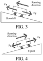
- Fig. 3 shows a stress condition when the vehicle stands on the ramp, the head of the vehicle is downward and the vehicle is ready to reverse.
- the vehicle In a reversing starting process, within a period of time that the brake pedal is loosened and the accelerator pedal is stepped on, the vehicle is subjected to upward driving force Fu parallel to the ramp and slip force Fg, wherein the slip force Fg is a resultant force of the downward component force of the self-gravity of the vehicle along the slope and the friction force of the pavement to the vehicle.
- the entire vehicle is subjected to the resultant force downward along the slope, the vehicle is short of power, and may result in a slipping downward tendency of the vehicle, that is, the vehicle may be in a front slip state due to downhill reversing.
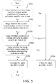
- Fig. 4 shows a stress condition when the vehicle stands on the ramp, the head of the vehicle is upward and the vehicle is ready to start.
- the vehicle In a starting process, within a period of time that the brake pedal is loosened and the accelerator pedal is stepped on, the vehicle is subjected to the upward driving force Fu parallel to the ramp and the slip force Fg, wherein the slip force Fg is the resultant force of the downward component force of the self-gravity of the vehicle along the slope and the friction force of the pavement to the vehicle.
- the entire vehicle is subjected to the resultant force downward along the slope, the vehicle is short of power, and may result in a slipping downward tendency of the vehicle, that is, the vehicle may be in a rear slip state due to uphill starting.
- the preset torque may be calibrated according to the slip force of the vehicle on different ramps. It should be understood that when the vehicle is driven according to the preset torque, the vehicle may be kept to not slide down, namely the vehicle does not slip.
- the ramp auxiliary system when the vehicle is driven according to the preset torque, whether the driving force corresponding to the entire actual output torque of the vehicle is greater than the slip force of the vehicle on the ramp or not is also judged, wherein if the driving force corresponding to the entire actual output torque of the vehicle is greater than the slip force of the vehicle on the ramp, the ramp auxiliary system is closed; if the driving force corresponding to the entire actual output torque of the vehicle is less than or equal to the slip force of the vehicle on the ramp, whether the time that the vehicle is in the torque keeping mode reaches preset time or not is judged; and if the time that the vehicle is in the torque keeping mode reaches the preset time, the ramp auxiliary system is closed.
- the control method of the ramp auxiliary system of the vehicle includes: when the ramp auxiliary system meets the preset activation conditions, activating the ramp auxiliary system; judging whether to control the vehicle to be in the torque keeping mode or not according to the current state information of the vehicle; and when the vehicle is in the torque keeping mode, driving the vehicle according to the preset torque to prevent the vehicle from slipping. Therefore, the running state of the vehicle may be accurately and comprehensively judged in advance, and driving control may be automatically performed on the vehicle in time to prevent the vehicle from slipping, thereby improving the safety of the vehicle.
- judging whether the ramp auxiliary system meets the preset activation conditions or not specifically may specifically include:
- control method of the ramp auxiliary system of the vehicle also may include the following steps:
- this application also provides a ramp auxiliary system of a vehicle.
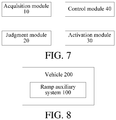
- the ramp auxiliary system of the vehicle includes an acquisition module 10, a judgment module 20, an activation module 30 and a control module 40,
- the acquisition module 10 is used for acquiring current state information of the vehicle; the judgment module 20 is used for judging whether the ramp auxiliary system meets preset activation conditions or not according to the current state information, wherein the preset activation conditions are used for activating the ramp auxiliary system; the activation module 30 is used for activating the ramp auxiliary system when the ramp auxiliary system meets the preset activation conditions; and the control module 40 is used for judging whether to control the vehicle to be in a torque keeping mode or not according to the current state information when the ramp auxiliary system is activated, and driving the vehicle according to preset torque when the vehicle is in the torque keeping mode, to prevent the vehicle from slipping, wherein the torque for driving the vehicle is kept unchanged in the torque keeping mode.
- the current state information of the vehicle includes at least one of the current gear of the vehicle, the current vehicle speed of the vehicle, the current slope of the vehicle, the accelerator pedal information of the vehicle, the brake pedal information of the vehicle, the rotation speed information of the rim motors, the orientation information of the head of the vehicle and the like.
- the vehicle according to the embodiment of this application also may include wheel speed sensors 1fl, 1fr, 1rl and 1rr which are arranged corresponding to each wheel and are used for respectively acquiring current rotation speeds of a front left wheel 2fl, a front right wheel 2fr, a rear left wheel 2rl and a rear right wheel 2rr. After the current rotation speeds of the wheels are acquired, the current vehicle speed of the vehicle may be further acquired according to the relationship between the rotation speeds of the wheels and the vehicle speed.
- wheel speed sensors 1fl, 1fr, 1rl and 1rr which are arranged corresponding to each wheel and are used for respectively acquiring current rotation speeds of a front left wheel 2fl, a front right wheel 2fr, a rear left wheel 2rl and a rear right wheel 2rr.
- the vehicle also may include an ECU and an MCU.
- the MCU may control the magnitude and direction of the driving force and brake force of each rim motor, and the MCU also may acquire the rotation speed information of each rim motor, wherein the MCU may acquire the rotation speed of a single rim motor and also can acquire the rotation speeds of a plurality of rim motors or all rim motors.
- the current gear of the vehicle, the current slope of the vehicle, the accelerator pedal information of the vehicle, the brake pedal information of the vehicle and the orientation information of the head of the vehicle may be respectively acquired by the ECU through a gear sensor, a slope sensor, an accelerator pedal sensor, a brake pedal sensor and a gravity sensor.
- the judgment module 20 may control the ramp auxiliary system to be in an activation standby state according to the current gear of the vehicle and the current slope of the vehicle. After the ramp auxiliary system is in the activation standby state, the judgment module 20 may judge whether the ramp auxiliary system meets the preset conditions (conditions of triggering activation) or not according to the current vehicle speed of the vehicle, the accelerator pedal information of the vehicle and the brake pedal information of the vehicle, and judge that the ramp auxiliary system meets the preset activation conditions when the conditions of triggering activation are met.
- the activation standby state is used for indicating that the ramp auxiliary system is already started and waits for activation.
- the judgment module 20 may control the ramp auxiliary system to be in the activation standby state. After the ramp auxiliary system is in the activation standby state, if the current vehicle speed of the vehicle is zero, and when the accelerator pedal of the vehicle is not stepped on and the brake pedal of the vehicle is stepped on, brake force is greater than the slip force of the vehicle on a ramp, namely the preset conditions are met, the judgment module 20 may judge that the ramp auxiliary system meets the preset activation conditions.
- the control module 40 may further judge whether to control the vehicle to be in a torque keeping mode or not according to the current state information. Specifically, the control module 40 may judge whether the entire driving force of the vehicle is greater than the slip force of the vehicle on the ramp or not according to the accelerator pedal information of the vehicle, the brake pedal information, the current gear of the vehicle, the rotation speed information of the rim motors and the orientation information of the head of the vehicle.
- the slip force is equal to the downward component force of the self-gravity of the vehicle along the slope minus the upward friction force along the slope; when the vehicle normally starts, the slip force is equal to the downward component force of the self-gravity of the vehicle along the slope plus the downward friction force along the slope.
- the control module 40 judges that the vehicle may be in a slip state and controls the vehicle to be in the torque keeping mode, wherein the slip state includes a front slip state due to downhill reversing and a rear slip state due to uphill starting.
- Fig. 3 shows a stress condition when the vehicle stands on the ramp, the head of the vehicle is downward and the vehicle is ready to reverse.
- the vehicle In a reversing starting process, within a period of time that the brake pedal is loosened and the accelerator pedal is stepped on, the vehicle is subjected to upward driving force Fu parallel to the ramp and slip force Fg, wherein the slip force Fg is a resultant force of the downward component force of the self-gravity of the vehicle along the slope and the friction force of the pavement to the vehicle.
- the entire vehicle is subjected to the resultant force downward along the slope, the vehicle is short of power, and may result in a slipping downward tendency of the vehicle, that is, the vehicle may be in a front slip state due to downhill reversing.
- Fig. 4 shows a stress condition when the vehicle stands on the ramp, the head of the vehicle is upward and the vehicle is ready to start.
- the vehicle In a starting process, within a period of time that the brake pedal is loosened and the accelerator pedal is stepped on, the vehicle is subjected to the upward driving force Fu parallel to the ramp and the slip force Fg, wherein the slip force Fg is a resultant force of the downward component force of the self-gravity of the vehicle along the slope and the friction force of the pavement to the vehicle.
- the entire vehicle is subjected to the resultant force downward along the slope, the vehicle is short of power, and may result in a slipping downward tendency of the vehicle, that is, the vehicle may be in a rear slip state due to uphill starting.
- the preset torque value may be calibrated according to the slip force of the vehicle on different ramps. It should be understood that when the vehicle is subjected to driving control according to the preset torque value, the vehicle can be kept to not slide down, namely the vehicle does not slip.
- control module 40 when the control module 40 drives the vehicle according to the preset torque, whether the driving force corresponding to the entire actual output torque of the vehicle is greater than the slip force of the vehicle on the ramp or not is also judged, wherein if the driving force corresponding to the entire actual output torque of the vehicle is greater than the slip force of the vehicle on the ramp, the control module 40 closes the ramp auxiliary system; if the driving force corresponding to the entire actual output torque of the vehicle is less than or equal to the slip force of the vehicle on the ramp, the control module 40 judges whether the time that the vehicle is in the torque keeping mode reaches preset time or not; and if the time that the vehicle is in the torque keeping mode reaches the preset time, the control module closes the ramp auxiliary system.
- the activation module activates the ramp auxiliary system, and the control module judges whether to control the vehicle to be in the torque keeping mode or not according to the current state information of the vehicle; and when the vehicle is in the torque keeping mode, the control module performs driving control according to the preset torque to prevent the vehicle from slipping. Therefore, the running state of the vehicle can be accurately and comprehensively judged in advance, and driving control can be automatically performed on the vehicle in time to prevent the vehicle from slipping, thereby improving the safety of the vehicle.
- this application also provides a vehicle.
- the vehicle 200 includes the ramp auxiliary system 100 provided by the above embodiment of this application, and the specific implementation mode may refer to the above embodiment. In order to avoid redundancy, the descriptions thereof are omitted herein.
- the running state of the vehicle according to the embodiment of this application can be accurately and comprehensively judged in advance, and driving control can be automatically performed on the vehicle in time to prevent the vehicle from slipping, thereby improving the safety of the vehicle.
- this application also provides a computer storage medium used for storing a computer instruction.
- the computer instruction is executed by a controller of equipment, the control method of the ramp auxiliary system of the vehicle is executed.
- orientations or position relationships indicated by terms such as “center”, “longitudinal”, “transverse”, “length”, “width”, “thickness”, “up”, “down”, “front”, “back”, “left”, “right”, “vertical”, “horizontal”, “top”, “bottom”, “inner”, “outer”, “clockwise”, “counterclockwise”, “axial”, “radial”, and “circumferential” are orientations or position relationship shown based on the accompanying drawings, and are merely used for describing this application and simplifying the description, rather than indicating or implying that the apparatus or element should have a particular orientation or be constructed and operated in a particular orientation, and therefore, should not be construed as a limitation on this application.
- first and second are used only for description purposes, and shall not be understood as indicating or suggesting relative importance or implicitly indicating a quantity of indicated technical features. Therefore, features modified by “first “ and “second” may explicitly or implicitly include one or more features. In descriptions of this application, “multiple” means two or more, unless otherwise defined clearly and specifically.
- mount should be understood in a generalized manner, for example, may be understood as fixed connection, detachable connection, or integration; or may be understood as mechanical connection, electrical connection, or mutual communication; or may be understood as direct connection, or indirect connection by means of a medium, or internal communication of two elements or a mutual relationship between two elements.
- fix should be understood in a generalized manner, for example, may be understood as fixed connection, detachable connection, or integration; or may be understood as mechanical connection, electrical connection, or mutual communication; or may be understood as direct connection, or indirect connection by means of a medium, or internal communication of two elements or a mutual relationship between two elements.
Landscapes
- Engineering & Computer Science (AREA)
- Power Engineering (AREA)
- Transportation (AREA)
- Mechanical Engineering (AREA)
- Electric Propulsion And Braking For Vehicles (AREA)
- Hybrid Electric Vehicles (AREA)
- Control Of Transmission Device (AREA)
Abstract
Description
- This application is based on and claims priority to Chinese Patent Application No.
201611069046.4, filed on November 28, 2016 - This application relates to the technical field of vehicles and particularly relates to a control method of a ramp auxiliary system of a vehicle, a ramp auxiliary system of a vehicle, and a vehicle.
- With the popularity of new energy vehicles, more and more drivers are concerned about the running comfort of vehicles. Specific to the problem of slip due to ramp starting, in related technologies, a method for controlling the starting of a vehicle on a ramp is not reliable enough, and the safety of the vehicle is difficult to ensure.
- This application aims to solve at least one of the technical problems in the above technology to some extent. Therefore, this application is directed to a control method of a ramp auxiliary system of a vehicle, and the control method can accurately and comprehensively judge the running state of the vehicle in advance and can automatically drive the vehicle in time to prevent the vehicle from slipping, thereby improving the safety of the vehicle.
- This application is also directed to a ramp auxiliary system of a vehicle.
- This application is further directed to a vehicle.
- In order to achieve the above objectives, a first embodiment of this application provides a control method of a ramp auxiliary system of a vehicle, wherein the vehicle is driven by a rim motor. The method includes: acquiring current state information of the vehicle; judging whether the ramp auxiliary system meets preset activation conditions or not according to the current state information, wherein the preset activation conditions are used for activating the ramp auxiliary system; activating the ramp auxiliary system if the ramp auxiliary system meets the preset activation conditions; judging whether to control the vehicle to be in a torque keeping mode or not according to the current state information, wherein the torque for driving the vehicle is kept unchanged in the torque keeping mode; and when the vehicle is in the torque keeping mode, driving the vehicle according to the preset torque to prevent the vehicle from slipping.
- The control method of the ramp auxiliary system of the vehicle according to the embodiment of this application includes: when the ramp auxiliary system meets the preset activation conditions, activating the ramp auxiliary system; judging whether to control the vehicle to be in the torque keeping mode or not according to the current state information of the vehicle; and when the vehicle is in the torque keeping mode, driving the vehicle according to the preset torque to prevent the vehicle from slipping. Therefore, the running state of the vehicle can be accurately and comprehensively judged in advance, and driving control can be automatically performed on the vehicle in time to prevent the vehicle from slipping, thereby improving the safety of the vehicle.
- In order to achieve the above objectives, a second embodiment of this application provides a ramp auxiliary system of a vehicle, wherein the vehicle is driven by a rim motor. The system includes an acquisition module which is used for acquiring current state information of the vehicle; a judgment module which is used for judging whether the ramp auxiliary system meets preset activation conditions or not according to the current state information, wherein the preset activation conditions are used for activating the ramp auxiliary system; an activation module which is used for activating the ramp auxiliary system when the ramp auxiliary system meets the preset activation conditions; and a control module which is used for judging whether to control the vehicle to be in a torque keeping mode or not according to the current state information when the ramp auxiliary system is activated, and driving the vehicle according to preset torque when the vehicle is in the torque keeping mode to prevent the vehicle from slipping, wherein the torque for driving the vehicle is kept unchanged in the torque keeping mode.
- When the ramp auxiliary system of the vehicle according to the embodiment of this application meets the preset activation conditions, the activation module activates the ramp auxiliary system, and the control module judges whether to control the vehicle to be in the torque keeping mode or not according to the current state information of the vehicle; and when the vehicle is in the torque keeping mode, the control module drives the vehicle according to the preset torque to prevent the vehicle from slipping. Therefore, the running state of the vehicle can be accurately and comprehensively judged in advance, and driving control can be automatically performed on the vehicle in time to prevent the vehicle from slipping, thereby improving the safety of the vehicle.
- In order to achieve the above objectives, a third embodiment of this application provides a vehicle, and the vehicle includes the ramp auxiliary system of the vehicle according to the second embodiment of this application.
- The running state of the vehicle according to the embodiment of this application can be accurately and comprehensively judged in advance, and driving control can be automatically performed in time to prevent the vehicle from slipping, thereby improving the safety.
- In order to achieve the above objectives, a fourth embodiment of this application provides a computer storage medium used for storing a computer instruction, wherein when the computer instruction is executed by a controller of equipment, the control method of the ramp auxiliary system of the vehicle is executed.
- Additional aspects and advantages of embodiments of this application will be given in part in the following descriptions, become apparent in part from the following descriptions, or be learned from the practice of the embodiments of this application.
-
-
Fig. 1 is a flow diagram of a control method of a ramp auxiliary system of a vehicle according to one embodiment of this application; -
Fig. 2 is a structural schematic diagram of a vehicle according to one embodiment of this application; -
Fig. 3 is a stress schematic diagram of a downhill reversing vehicle according to one embodiment of this application; -
Fig. 4 is a stress schematic diagram of an uphill starting vehicle according to one embodiment of this application; -
Fig. 5 is a flow diagram of a control method of a ramp auxiliary system of a vehicle according to one specific embodiment of this application; -
Fig. 6 is a flow diagram of a control method of a ramp auxiliary system of a vehicle according to another specific embodiment of this application; -
Fig. 7 is a block diagram of a ramp auxiliary system of a vehicle according to one embodiment of this application; and -
Fig. 8 is a block diagram of a vehicle according to one embodiment of this application. - The following describes in detail embodiments of this application. Examples of the embodiments are shown in the accompanying drawings, where reference signs that are the same or similar from beginning to end represent same or similar components or components that have same or similar functions. The embodiments described below with reference to the accompanying drawings are exemplary, and are used for explaining rather than limiting this application.
- A vehicle, a ramp auxiliary system of the vehicle and a control method thereof according to the embodiments of this application are described below with reference to the accompanying drawings.
-
Fig. 1 is a flow diagram of a control method of a ramp auxiliary system of a vehicle according to one embodiment of this application. - It should be noted that the vehicle according to the embodiment of this application may be driven by rim motors, and each wheel of the vehicle may be correspondingly provided with one rim motor. As shown in
Fig. 2 , a front left wheel 2fl is driven or braked by a rim motor 3fl, a front right wheel 2fr is driven or braked by a rim motor 3fr, a rear left wheel 2rl is driven or braked by a rim motor 3rl, and a rear right wheel 2rr is driven or braked by a rim motor 3rr. - As shown in
Fig. 1 , the control method of the ramp auxiliary system of the vehicle according to the embodiment of this application includes the followings. - S1, acquire current state information of the vehicle, and judge whether the ramp auxiliary system meets preset activation conditions or not according to the current state information.
- In one embodiment of this application, the preset activation conditions are used for activating the ramp auxiliary system.
- In one embodiment of this application, the current state information of the vehicle includes at least one of the current gear of the vehicle, the current vehicle speed of the vehicle, the current slope of the vehicle, accelerator pedal information of the vehicle, brake pedal information of the vehicle, rotation speed information of the rim motors, orientation information of a head of the vehicle and the like.
- As shown in
Fig. 2 , the vehicle according to the embodiment of this application also may include wheel speed sensors 1fl, 1fr, 1rl and 1rr which are arranged corresponding to each wheel and are used for respectively acquiring current rotation speeds of the front left wheel 2fl, the front right wheel 2fr, the rear left wheel 2rl and the rear right wheel 2rr. After the current rotation speeds of the wheels are acquired, the current vehicle speed of the vehicle may be further acquired according to the relationship between the rotation speeds of the wheels and the vehicle speed. - As shown in
Fig. 2 , the vehicle according to the embodiment of this application also may include an ECU (Electronic Control Unit) and an MCU (Motor Control Unit). The MCU may control the magnitude and direction of driving force and brake force of each rim motor, and the MCU also may acquire rotation speed information of each rim motor. The MCU may acquire the rotation speed of a single rim motor and also may acquire the rotation speeds of multiple or all of the rim motors. In one embodiment of this application, the current gear of the vehicle, the current slope of the vehicle, the accelerator pedal information of the vehicle, the brake pedal information of the vehicle and the orientation information of the head of the vehicle may be respectively acquired by the ECU through a gear sensor, a slope sensor, an accelerator pedal sensor, a brake pedal sensor and a gravity sensor. - In one embodiment of this application, the ramp auxiliary system may be controlled to be in an activation standby state according to the current gear of the vehicle and the current slope of the vehicle. After the ramp auxiliary system is in the activation standby state, whether the ramp auxiliary system meets the preset conditions (namely conditions of triggering activation) or not may be judged according to the current vehicle speed of the vehicle, the accelerator pedal information of the vehicle and the brake pedal information of the vehicle, and if so, the ramp auxiliary system is judged to meet the preset activation conditions. The activation standby state is used for indicating that the ramp auxiliary system is already started and waits for activation.
- Specifically, if the current gear of the vehicle is D or R and the current slope of the vehicle is not zero, the ramp auxiliary system may be controlled to be in the activation standby state. After the ramp auxiliary system is in the activation standby state, if the current vehicle speed of the vehicle is zero, and when the accelerator pedal of the vehicle is not stepped on and the brake pedal of the vehicle is stepped on, brake force is greater than slip force of the vehicle on a ramp, namely the preset conditions are met, the ramp auxiliary system is judged to meet the preset activation conditions.
- S2, if the ramp auxiliary system meets the preset activation conditions, activate the ramp auxiliary system, and judge whether to control the vehicle to be in a torque keeping mode or not according to the current state information of the vehicle, wherein torque for driving the vehicle is kept unchanged in the torque keeping mode.
- After the ramp auxiliary system is activated, whether to control the vehicle to be in the torque keeping mode or not may be further judged according to the current state information. Specifically, whether the entire driving force of the vehicle is greater than the slip force of the vehicle on the ramp or not may be judged according to the accelerator pedal information of the vehicle, the brake pedal information of the vehicle, the current gear of the vehicle, the rotation speed information of the rim motors and the orientation information of the head of the vehicle. When the vehicle stands on the ramp, the slip force is equal to a downward component force of the self-gravity of the vehicle along the slope minus an upward friction force along the slope; and when the vehicle normally starts, the slip force is equal to the downward component force of the self-gravity of the vehicle along the slope plus a downward friction force along the slope. If the entire driving force is less than or equal to the slip force, judge that the vehicle may be in a slip state, and the vehicle is controlled to be in the torque keeping mode, wherein the slip state includes a front slip state due to downhill reversing and a rear slip state due to uphill starting.
-
Fig. 3 shows a stress condition when the vehicle stands on the ramp, the head of the vehicle is downward and the vehicle is ready to reverse. In a reversing starting process, within a period of time that the brake pedal is loosened and the accelerator pedal is stepped on, the vehicle is subjected to upward driving force Fu parallel to the ramp and slip force Fg, wherein the slip force Fg is a resultant force of the downward component force of the self-gravity of the vehicle along the slope and the friction force of the pavement to the vehicle. When the driving force Fu is less than the slip force Fg, the entire vehicle is subjected to the resultant force downward along the slope, the vehicle is short of power, and may result in a slipping downward tendency of the vehicle, that is, the vehicle may be in a front slip state due to downhill reversing. -
Fig. 4 shows a stress condition when the vehicle stands on the ramp, the head of the vehicle is upward and the vehicle is ready to start. In a starting process, within a period of time that the brake pedal is loosened and the accelerator pedal is stepped on, the vehicle is subjected to the upward driving force Fu parallel to the ramp and the slip force Fg, wherein the slip force Fg is the resultant force of the downward component force of the self-gravity of the vehicle along the slope and the friction force of the pavement to the vehicle. When the driving force Fu is less than the slip force Fg, the entire vehicle is subjected to the resultant force downward along the slope, the vehicle is short of power, and may result in a slipping downward tendency of the vehicle, that is, the vehicle may be in a rear slip state due to uphill starting. - S3, when the vehicle is in the torque keeping mode, drive the vehicle according to the preset torque to prevent the vehicle from slipping.
- In one embodiment of this application, the preset torque may be calibrated according to the slip force of the vehicle on different ramps. It should be understood that when the vehicle is driven according to the preset torque, the vehicle may be kept to not slide down, namely the vehicle does not slip.
- In addition, in one embodiment of this application, when the vehicle is driven according to the preset torque, whether the driving force corresponding to the entire actual output torque of the vehicle is greater than the slip force of the vehicle on the ramp or not is also judged, wherein if the driving force corresponding to the entire actual output torque of the vehicle is greater than the slip force of the vehicle on the ramp, the ramp auxiliary system is closed; if the driving force corresponding to the entire actual output torque of the vehicle is less than or equal to the slip force of the vehicle on the ramp, whether the time that the vehicle is in the torque keeping mode reaches preset time or not is judged; and if the time that the vehicle is in the torque keeping mode reaches the preset time, the ramp auxiliary system is closed.
- The control method of the ramp auxiliary system of the vehicle according to the embodiment of this application includes: when the ramp auxiliary system meets the preset activation conditions, activating the ramp auxiliary system; judging whether to control the vehicle to be in the torque keeping mode or not according to the current state information of the vehicle; and when the vehicle is in the torque keeping mode, driving the vehicle according to the preset torque to prevent the vehicle from slipping. Therefore, the running state of the vehicle may be accurately and comprehensively judged in advance, and driving control may be automatically performed on the vehicle in time to prevent the vehicle from slipping, thereby improving the safety of the vehicle.
- In one specific embodiment of this application, as shown in
Fig. 5 , in the control method of the ramp auxiliary system of the vehicle, judging whether the ramp auxiliary system meets the preset activation conditions or not specifically may specifically include: - S501, judge whether the current ramp auxiliary system meets the conditions of being in an activation standby state or not; if so, execute S502; and if not, execute step S506, end the present judgment, and then, perform the next judgment.
- S502, judge whether the current ramp auxiliary system is in the activation standby state or not; if so, execute step S503; and if not, execute step S506, end the present judgment, and then, perform the next judgment.
- S503, judge whether the conditions of closing the ramp auxiliary system are met or not; if not, execute step S504; and if so, execute step S506.
- S504, judge whether the ramp auxiliary system meets the conditions of triggering activation or not; if so, execute step S505; and if not, execute step S506.
- S505, activate the ramp auxiliary system.
- S506, close the ramp auxiliary system.
- In one specific embodiment of this application, as shown in
Fig. 6 , the control method of the ramp auxiliary system of the vehicle also may include the following steps: - S601, judge whether the ramp auxiliary system is activated or not; if so, execute step S602; if not, end a procedure.
- S602, judge whether the vehicle is in a torque keeping mode or not; if so, execute step S603; and if not, end the procedure.
- S603, drive the vehicle according to preset torque.
- S604, judge whether entire driving force is greater than slip force or not; if so, end the procedure; and if not, execute step S605.
- S605, judge whether the time that the vehicle is in the torque keeping mode reaches preset time or not; if so, end the procedure; and if not, execute step S606.
- S606, judge whether to keep the torque keeping mode or not, wherein the conditions of judging whether to keep the torque keeping mode or not may be identical to the conditions of judging whether to control the vehicle to be in the torque keeping mode or not; if so, return to step S603; and if not, end the procedure.
- In order to realize the control method of the ramp auxiliary system of the vehicle according to the above embodiment, this application also provides a ramp auxiliary system of a vehicle.
- As shown in
Fig. 7 , the ramp auxiliary system of the vehicle according to the embodiment of this application includes anacquisition module 10, ajudgment module 20, anactivation module 30 and acontrol module 40, - wherein the
acquisition module 10 is used for acquiring current state information of the vehicle; thejudgment module 20 is used for judging whether the ramp auxiliary system meets preset activation conditions or not according to the current state information, wherein the preset activation conditions are used for activating the ramp auxiliary system; theactivation module 30 is used for activating the ramp auxiliary system when the ramp auxiliary system meets the preset activation conditions; and thecontrol module 40 is used for judging whether to control the vehicle to be in a torque keeping mode or not according to the current state information when the ramp auxiliary system is activated, and driving the vehicle according to preset torque when the vehicle is in the torque keeping mode, to prevent the vehicle from slipping, wherein the torque for driving the vehicle is kept unchanged in the torque keeping mode. - In one embodiment of this application, the current state information of the vehicle includes at least one of the current gear of the vehicle, the current vehicle speed of the vehicle, the current slope of the vehicle, the accelerator pedal information of the vehicle, the brake pedal information of the vehicle, the rotation speed information of the rim motors, the orientation information of the head of the vehicle and the like.
- As shown in
Fig. 2 , the vehicle according to the embodiment of this application also may include wheel speed sensors 1fl, 1fr, 1rl and 1rr which are arranged corresponding to each wheel and are used for respectively acquiring current rotation speeds of a front left wheel 2fl, a front right wheel 2fr, a rear left wheel 2rl and a rear right wheel 2rr. After the current rotation speeds of the wheels are acquired, the current vehicle speed of the vehicle may be further acquired according to the relationship between the rotation speeds of the wheels and the vehicle speed. - As shown in
Fig. 2 , the vehicle according to the embodiment of this application also may include an ECU and an MCU. The MCU may control the magnitude and direction of the driving force and brake force of each rim motor, and the MCU also may acquire the rotation speed information of each rim motor, wherein the MCU may acquire the rotation speed of a single rim motor and also can acquire the rotation speeds of a plurality of rim motors or all rim motors. In one embodiment of this application, the current gear of the vehicle, the current slope of the vehicle, the accelerator pedal information of the vehicle, the brake pedal information of the vehicle and the orientation information of the head of the vehicle may be respectively acquired by the ECU through a gear sensor, a slope sensor, an accelerator pedal sensor, a brake pedal sensor and a gravity sensor. - In one embodiment of this application, the
judgment module 20 may control the ramp auxiliary system to be in an activation standby state according to the current gear of the vehicle and the current slope of the vehicle. After the ramp auxiliary system is in the activation standby state, thejudgment module 20 may judge whether the ramp auxiliary system meets the preset conditions (conditions of triggering activation) or not according to the current vehicle speed of the vehicle, the accelerator pedal information of the vehicle and the brake pedal information of the vehicle, and judge that the ramp auxiliary system meets the preset activation conditions when the conditions of triggering activation are met. The activation standby state is used for indicating that the ramp auxiliary system is already started and waits for activation. - Specifically, if the current gear of the vehicle is D or R and the current slope of the vehicle is not zero, the
judgment module 20 may control the ramp auxiliary system to be in the activation standby state. After the ramp auxiliary system is in the activation standby state, if the current vehicle speed of the vehicle is zero, and when the accelerator pedal of the vehicle is not stepped on and the brake pedal of the vehicle is stepped on, brake force is greater than the slip force of the vehicle on a ramp, namely the preset conditions are met, thejudgment module 20 may judge that the ramp auxiliary system meets the preset activation conditions. - After the ramp auxiliary system is activated, the
control module 40 may further judge whether to control the vehicle to be in a torque keeping mode or not according to the current state information. Specifically, thecontrol module 40 may judge whether the entire driving force of the vehicle is greater than the slip force of the vehicle on the ramp or not according to the accelerator pedal information of the vehicle, the brake pedal information, the current gear of the vehicle, the rotation speed information of the rim motors and the orientation information of the head of the vehicle. When the vehicle stands on the ramp, the slip force is equal to the downward component force of the self-gravity of the vehicle along the slope minus the upward friction force along the slope; when the vehicle normally starts, the slip force is equal to the downward component force of the self-gravity of the vehicle along the slope plus the downward friction force along the slope. If the entire driving force is less than or equal to the slip force, thecontrol module 40 judges that the vehicle may be in a slip state and controls the vehicle to be in the torque keeping mode, wherein the slip state includes a front slip state due to downhill reversing and a rear slip state due to uphill starting. -
Fig. 3 shows a stress condition when the vehicle stands on the ramp, the head of the vehicle is downward and the vehicle is ready to reverse. In a reversing starting process, within a period of time that the brake pedal is loosened and the accelerator pedal is stepped on, the vehicle is subjected to upward driving force Fu parallel to the ramp and slip force Fg, wherein the slip force Fg is a resultant force of the downward component force of the self-gravity of the vehicle along the slope and the friction force of the pavement to the vehicle. When the driving force Fu is less than the slip force Fg, the entire vehicle is subjected to the resultant force downward along the slope, the vehicle is short of power, and may result in a slipping downward tendency of the vehicle, that is, the vehicle may be in a front slip state due to downhill reversing. -
Fig. 4 shows a stress condition when the vehicle stands on the ramp, the head of the vehicle is upward and the vehicle is ready to start. In a starting process, within a period of time that the brake pedal is loosened and the accelerator pedal is stepped on, the vehicle is subjected to the upward driving force Fu parallel to the ramp and the slip force Fg, wherein the slip force Fg is a resultant force of the downward component force of the self-gravity of the vehicle along the slope and the friction force of the pavement to the vehicle. When the driving force Fu is less than the slip force Fg, the entire vehicle is subjected to the resultant force downward along the slope, the vehicle is short of power, and may result in a slipping downward tendency of the vehicle, that is, the vehicle may be in a rear slip state due to uphill starting. - In one embodiment of this application, the preset torque value may be calibrated according to the slip force of the vehicle on different ramps. It should be understood that when the vehicle is subjected to driving control according to the preset torque value, the vehicle can be kept to not slide down, namely the vehicle does not slip.
- In addition, in one embodiment of this application, when the
control module 40 drives the vehicle according to the preset torque, whether the driving force corresponding to the entire actual output torque of the vehicle is greater than the slip force of the vehicle on the ramp or not is also judged, wherein if the driving force corresponding to the entire actual output torque of the vehicle is greater than the slip force of the vehicle on the ramp, thecontrol module 40 closes the ramp auxiliary system; if the driving force corresponding to the entire actual output torque of the vehicle is less than or equal to the slip force of the vehicle on the ramp, thecontrol module 40 judges whether the time that the vehicle is in the torque keeping mode reaches preset time or not; and if the time that the vehicle is in the torque keeping mode reaches the preset time, the control module closes the ramp auxiliary system. - When the ramp auxiliary system of the vehicle according to the embodiment of this application meets the preset activation conditions, the activation module activates the ramp auxiliary system, and the control module judges whether to control the vehicle to be in the torque keeping mode or not according to the current state information of the vehicle; and when the vehicle is in the torque keeping mode, the control module performs driving control according to the preset torque to prevent the vehicle from slipping. Therefore, the running state of the vehicle can be accurately and comprehensively judged in advance, and driving control can be automatically performed on the vehicle in time to prevent the vehicle from slipping, thereby improving the safety of the vehicle.
- Corresponding to the above embodiment, this application also provides a vehicle.
- As shown in
Fig. 8 , thevehicle 200 according to the embodiment of this application includes the rampauxiliary system 100 provided by the above embodiment of this application, and the specific implementation mode may refer to the above embodiment. In order to avoid redundancy, the descriptions thereof are omitted herein. - The running state of the vehicle according to the embodiment of this application can be accurately and comprehensively judged in advance, and driving control can be automatically performed on the vehicle in time to prevent the vehicle from slipping, thereby improving the safety of the vehicle.
- Corresponding to the above embodiment, this application also provides a computer storage medium used for storing a computer instruction. When the computer instruction is executed by a controller of equipment, the control method of the ramp auxiliary system of the vehicle is executed.
- In the description of this application, it should be understood that, orientations or position relationships indicated by terms such as "center", "longitudinal", "transverse", "length", "width", "thickness", "up", "down", "front", "back", "left", "right", "vertical", "horizontal", "top", "bottom", "inner", "outer", "clockwise", "counterclockwise", "axial", "radial", and "circumferential" are orientations or position relationship shown based on the accompanying drawings, and are merely used for describing this application and simplifying the description, rather than indicating or implying that the apparatus or element should have a particular orientation or be constructed and operated in a particular orientation, and therefore, should not be construed as a limitation on this application.
- In addition, terms "first" and "second" are used only for description purposes, and shall not be understood as indicating or suggesting relative importance or implicitly indicating a quantity of indicated technical features. Therefore, features modified by "first " and "second " may explicitly or implicitly include one or more features. In descriptions of this application, "multiple" means two or more, unless otherwise defined clearly and specifically.
- In this application, unless otherwise clearly stipulated and limited, terms "mount", "connect", and "fix" should be understood in a generalized manner, for example, may be understood as fixed connection, detachable connection, or integration; or may be understood as mechanical connection, electrical connection, or mutual communication; or may be understood as direct connection, or indirect connection by means of a medium, or internal communication of two elements or a mutual relationship between two elements. A person of ordinary skill in the art may understand specific meanings of the terms in this application according to specific situations.
- In the descriptions of this specification, descriptions such as reference terms "an embodiment", "some embodiments", "example", "specific example", or "some examples" intend to indicate that specific features, structures, materials, or characteristics described with reference to embodiments or examples are included in at least one embodiment or example of this application. In this specification, schematic descriptions of the foregoing terms do not need to aim at a same embodiment or example. In addition, in a case that is not mutually contradictory, persons skilled in the art can combine or group different embodiments or examples that are described in this specification and features of the different embodiments or examples.
- Although the embodiments of this application are shown and described above, it can be understood that, the foregoing embodiments are exemplary, and cannot be construed as a limitation to this application. Within the scope of this application, a person of ordinary skill in the art may make changes, modifications, replacement, and variations to the foregoing embodiments.
Claims (14)
- A control method of a ramp auxiliary system of a vehicle, wherein the vehicle is driven by a rim motor, and the method comprises:acquiring current state information of the vehicle;judging whether the ramp auxiliary system meets preset activation conditions or not according to the current state information, wherein the preset activation conditions are used for activating the ramp auxiliary system;activating the ramp auxiliary system if the ramp auxiliary system meets the preset activation conditions;judging whether to control the vehicle to be in a torque keeping mode or not according to the current state information, wherein torque for driving the vehicle is kept unchanged in the torque keeping mode; andwhen the vehicle is in the torque keeping mode, driving the vehicle according to the preset torque to prevent the vehicle from slipping.
- The control method of the ramp auxiliary system of the vehicle according to claim 1, wherein the current state information of the vehicle includes at least one of the current gear of the vehicle, the current vehicle speed of the vehicle, the current slope of the vehicle, accelerator pedal information of the vehicle, brake pedal information of the vehicle, rotation speed information of the rim motor and orientation information of a head of the vehicle.
- The control method of the ramp auxiliary system of the vehicle according to claim 2, wherein judging whether the ramp auxiliary system meets the preset activation conditions or not according to the current state information comprises:controlling the ramp auxiliary system to be in an activation standby state according to the current gear of the vehicle and the current slope of the vehicle, wherein the activation standby state is used for indicating that the ramp auxiliary system is already started and waits for activation;after the ramp auxiliary system is in the activation standby state, judging whether the current vehicle speed of the vehicle, the accelerator pedal information of the vehicle and the brake pedal information of the vehicle meet the preset conditions or not; andif so, then judging that the ramp auxiliary system meets the preset activation conditions.
- The control method of the ramp auxiliary system of the vehicle according to claim 3, wherein the preset conditions comprises: the current vehicle speed of the vehicle is zero, and when an accelerator pedal of the vehicle is not stepped on and a brake pedal of the vehicle is stepped on, brake force is greater than slip force of the vehicle on a ramp.
- The control method of the ramp auxiliary system of the vehicle according to claim 2, wherein judging whether to control the vehicle to be in the torque keeping mode or not according to the current state information comprises:judging whether an entire driving force of the vehicle is greater than the slip force of the vehicle on a ramp or not according to the accelerator pedal information of the vehicle, the brake pedal information, the current gear of the vehicle, the rotation speed information of the rim motor and the orientation information of the head of the vehicle; andif the entire driving force is less than or equal to the slip force, then judging that the vehicle may be in a slip state, and controlling the vehicle to be in the torque keeping mode, wherein the slip state includes a front slip state due to downhill reversing and a rear slip state due to uphill starting.
- The control method of the ramp auxiliary system of the vehicle according to any one of claims 1 to 5, further comprising: when the vehicle is subjected to driving control by a preset torque value, to judge whether the driving force corresponding to entire actual output torque of the vehicle is greater than the slip force of the vehicle on the ramp or not;if the driving force corresponding to the entire actual output torque of the vehicle is greater than the slip force of the vehicle on the ramp, then closing the ramp auxiliary system;if the driving force corresponding to the entire actual output torque of the vehicle is less than or equal to the slip force of the vehicle on the ramp, then judging whether the time that the vehicle is in the torque keeping mode reaches preset time or not; andif the time that the vehicle is in the torque keeping mode reaches the preset time, then closing the ramp auxiliary system.
- A ramp auxiliary system of a vehicle, wherein the vehicle is driven by a rim motor, and the system comprises:an acquisition module which is used for acquiring current state information of the vehicle;a judgment module which is used for judging whether the ramp auxiliary system meets preset activation conditions or not according to the current state information, wherein the preset activation conditions are used for activating the ramp auxiliary system;an activation module which is used for activating the ramp auxiliary system when the ramp auxiliary system meets the preset activation conditions; anda control module which is used for judging whether to control the vehicle to be in a torque keeping mode or not according to the current state information when the ramp auxiliary system is activated, and driving the vehicle according to preset torque when the vehicle is in the torque keeping mode, to prevent the vehicle from slipping, wherein the torque for driving the vehicle is kept unchanged in the torque keeping mode.
- The ramp auxiliary system of the vehicle according to claim 7, wherein the current state information of the vehicle comprises at least one of the current gear of the vehicle, the current vehicle speed of the vehicle, the current slope of the vehicle, accelerator pedal information of the vehicle, brake pedal information of the vehicle, rotation speed information of the rim motor and orientation information of a head of the vehicle.
- The ramp auxiliary system of the vehicle according to claim 8, wherein the judgment module is used for controlling the ramp auxiliary system to be in an activation standby state according to the current gear of the vehicle and the current slope of the vehicle, the activation standby state is used for indicating that the ramp auxiliary system is already started and waits for activation, and the judgment module is used for judging whether the ramp auxiliary system meets the preset conditions or not according to the current vehicle speed of the vehicle, the accelerator pedal information of the vehicle and the brake pedal information of the vehicle after the ramp auxiliary system is in the activation standby state, and judging that the ramp auxiliary system meets the preset activation conditions when the preset conditions are met.
- The ramp auxiliary system of the vehicle according to claim 9, wherein the preset conditions comprise: the current vehicle speed of the vehicle is zero, and when an accelerator pedal of the vehicle is not stepped on and a brake pedal of the vehicle is stepped on, brake force is greater than slip force of the vehicle on a ramp.
- The ramp auxiliary system of the vehicle according to claim 8, wherein the control module is used for judging whether entire driving force of the vehicle is greater than slip force of the vehicle on a ramp or not according to the accelerator pedal information of the vehicle, the brake pedal information, the current gear of the vehicle, the rotation speed information of the rim motor and the orientation information of the head of the vehicle, judging that the vehicle may be in a slip state when the entire driving force is less than or equal to the slip force, and controlling the vehicle to be in a torque keeping mode, wherein the slip state includes a front slip state due to downhill reversing and a rear slip state due to uphill starting.
- The ramp auxiliary system of the vehicle according to any one of claims 7 to 11, wherein when the control module performs driving control on the vehicle by a preset torque value, the control module also judges whether driving force corresponding to entire actual output torque of the vehicle is greater than the slip force of the vehicle on the ramp or not, wherein if the driving force corresponding to the entire actual output torque of the vehicle is greater than the slip force of the vehicle on the ramp, the control module closes the ramp auxiliary system; if the driving force corresponding to the entire actual output torque of the vehicle is less than or equal to the slip force of the vehicle on the ramp, the control module judges whether the time that the vehicle is in the torque keeping mode reaches preset time or not; and if the time that the vehicle is in the torque keeping mode reaches the preset time, the control module closes the ramp auxiliary system.
- A vehicle, comprising the ramp auxiliary system of the vehicle according to any one of claims 7 to 12.
- A computer storage medium used for storing a computer instruction, wherein when the computer instruction is executed by a controller of equipment, the control method of the ramp auxiliary system of the vehicle according to any one of claims 1 to 6 is executed.
Applications Claiming Priority (2)
| Application Number | Priority Date | Filing Date | Title |
|---|---|---|---|
| CN201611069046.4A CN108116269B (en) | 2016-11-28 | 2016-11-28 | Vehicle, ramp assist system for vehicle, and control method thereof |
| PCT/CN2017/110845 WO2018095242A1 (en) | 2016-11-28 | 2017-11-14 | Vehicle, vehicle slope assist system, and control method thereof |
Publications (2)
| Publication Number | Publication Date |
|---|---|
| EP3546274A1 true EP3546274A1 (en) | 2019-10-02 |
| EP3546274A4 EP3546274A4 (en) | 2019-12-11 |
Family
ID=62195745
Family Applications (1)
| Application Number | Title | Priority Date | Filing Date |
|---|---|---|---|
| EP17874203.7A Withdrawn EP3546274A4 (en) | 2016-11-28 | 2017-11-14 | Vehicle, vehicle slope assist system, and control method thereof |
Country Status (5)
| Country | Link |
|---|---|
| US (1) | US20200055409A1 (en) |
| EP (1) | EP3546274A4 (en) |
| KR (1) | KR20190059967A (en) |
| CN (1) | CN108116269B (en) |
| WO (1) | WO2018095242A1 (en) |
Cited By (4)
| Publication number | Priority date | Publication date | Assignee | Title |
|---|---|---|---|---|
| CN111231695A (en) * | 2020-01-17 | 2020-06-05 | 浙江飞碟汽车制造有限公司 | Ramp auxiliary control method for driving motor system for pure electric truck |
| CN112622640A (en) * | 2021-01-05 | 2021-04-09 | 潍柴动力股份有限公司 | Ramp parking method and vehicle |
| WO2022184398A1 (en) * | 2021-03-05 | 2022-09-09 | Bayerische Motoren Werke Aktiengesellschaft | Method and control device for operating a roadbound all-wheel vehicle |
| EP4686597A1 (en) * | 2024-08-01 | 2026-02-04 | Robert Bosch GmbH | Method, apparatus, controller, vehicle and program product for controlling vehicle on ramp |
Families Citing this family (35)
| Publication number | Priority date | Publication date | Assignee | Title |
|---|---|---|---|---|
| CN108725259A (en) * | 2018-06-26 | 2018-11-02 | 南京恒天领锐汽车有限公司 | A kind of big slope starting control system of novel 4 wheel driven pure electric coach |
| CN110303901B (en) * | 2019-07-12 | 2022-06-14 | 重庆长安新能源汽车科技有限公司 | Automobile ramp auxiliary braking method and device and electric automobile |
| CN110435443B (en) * | 2019-08-19 | 2021-08-27 | 安徽江淮汽车集团股份有限公司 | Ramp auxiliary control method, device, equipment and storage medium |
| CN111169441B (en) * | 2020-01-09 | 2022-03-08 | 宁波吉利汽车研究开发有限公司 | Automatic parking control method, system and terminal |
| CN113771639B (en) * | 2020-06-08 | 2024-01-30 | 北京新能源汽车股份有限公司 | Torque control method and device and vehicle |
| CN111746303A (en) * | 2020-07-09 | 2020-10-09 | 长泰鑫顺泰实业发展有限公司 | Electric automobile control method |
| CN111907340A (en) * | 2020-07-14 | 2020-11-10 | 宝能(广州)汽车研究院有限公司 | Braking method for vehicle, motor controller and vehicle |
| CN112009264B (en) * | 2020-08-13 | 2021-12-28 | 吉利汽车研究院(宁波)有限公司 | Control method and device for preventing vehicle from sliding down slope and vehicle |
| CN112373450B (en) * | 2020-11-10 | 2022-04-05 | 上海拿森汽车电子有限公司 | Control method and device for vehicle auxiliary turning |
| CN112428985A (en) * | 2020-11-19 | 2021-03-02 | 宝能(广州)汽车研究院有限公司 | Downhill assist control method and vehicle employing the same |
| CN112498126B (en) * | 2020-12-16 | 2023-01-17 | 芜湖杰诺瑞汽车电器系统有限公司 | Zero-rotation-speed control method for automobile electric drive system |
| CN112622641B (en) * | 2021-01-07 | 2022-11-04 | 广西宁达汽车科技有限公司 | Vehicle control method, device and system |
| CN115071424B (en) * | 2021-03-01 | 2024-03-19 | 观致汽车有限公司 | Vehicle control method and vehicle |
| CN112895914B (en) * | 2021-03-01 | 2024-04-19 | 宜宾丰川动力科技有限公司 | Vehicle control method and device and controller of electronic equipment |
| CN115139797B (en) * | 2021-03-31 | 2024-09-10 | 比亚迪股份有限公司 | Vehicle control method, vehicle and computer readable storage medium |
| CN113119751B (en) * | 2021-05-12 | 2022-11-01 | 湖南三一智能控制设备有限公司 | Vehicle slope starting method and device, vehicle, electronic equipment and storage medium |
| CN115465112A (en) * | 2021-06-11 | 2022-12-13 | 格力博(江苏)股份有限公司 | Vehicle brake control method and system |
| CN113479073B (en) * | 2021-08-02 | 2024-05-17 | 潍柴动力股份有限公司 | Anti-slip control method and device, whole vehicle controller and storage medium |
| CN113788025B (en) * | 2021-08-27 | 2023-06-27 | 东风汽车集团股份有限公司 | Ramp detection method and device and vehicle |
| CN113829898B (en) * | 2021-11-15 | 2023-09-12 | 合众新能源汽车股份有限公司 | Vehicle control method and vehicle |
| CN114179627A (en) * | 2021-12-07 | 2022-03-15 | 惠州市深业新能源科技有限公司 | Electric vehicle with auxiliary function of starting on half slope and starting method thereof |
| CN114179621B (en) * | 2021-12-23 | 2023-04-28 | 奇瑞商用车(安徽)有限公司 | Method and device for controlling descent control of abrupt slope of vehicle |
| CN114475562B (en) * | 2021-12-28 | 2024-05-28 | 东风汽车集团股份有限公司 | A brake assist control method and system for following vehicles on a congested slope |
| CN114407897A (en) * | 2022-01-20 | 2022-04-29 | 东风汽车股份有限公司 | Vehicle ramp auxiliary function trigger control method, recording medium and system |
| CN114537396B (en) * | 2022-03-16 | 2026-04-28 | 安徽江淮汽车集团股份有限公司 | Adaptive control method and system for hill start assist function in automatic transmission commercial vehicles |
| CN115071445B (en) * | 2022-08-03 | 2026-01-02 | 奇瑞新能源汽车股份有限公司 | New energy vehicle crawl control method and system |
| CN115431986A (en) * | 2022-10-13 | 2022-12-06 | 贵州翰凯斯智能技术有限公司 | Transportation tool assisting method and device and storage medium |
| CN115648964B (en) * | 2022-10-28 | 2025-07-22 | 智新科技股份有限公司 | Electric automobile anti-slip control method and system based on motor controller |
| CN115675115B (en) * | 2022-11-01 | 2026-01-02 | 奇瑞新能源汽车股份有限公司 | Methods, devices, electric vehicles and storage media for providing ramp assist for electric vehicles |
| CN115817480A (en) * | 2022-11-29 | 2023-03-21 | 重庆长安汽车股份有限公司 | Adaptive cruise anti-slope-sliding control method and device, electronic equipment and storage medium |
| CN115771405A (en) * | 2022-12-05 | 2023-03-10 | 优跑汽车技术(上海)有限公司 | Control method, system and vehicle for starting a vehicle on a slope |
| CN116872899A (en) * | 2023-08-16 | 2023-10-13 | 奇瑞新能源汽车股份有限公司 | A pure electric vehicle CST system and control method |
| CN117141455A (en) * | 2023-09-12 | 2023-12-01 | 长城汽车股份有限公司 | Energy management control method, device, storage medium and vehicle for hybrid vehicle |
| CN117429275B (en) * | 2023-11-29 | 2024-07-19 | 深圳熙斯特新能源技术有限公司 | Motor torque control method, device, medium and equipment for electric vehicle on ramp |
| CN118722264A (en) * | 2024-07-19 | 2024-10-01 | 东风商用车有限公司 | A ramp assist system for medium and heavy trucks based on electric vehicles |
Family Cites Families (13)
| Publication number | Priority date | Publication date | Assignee | Title |
|---|---|---|---|---|
| CN101209682B (en) * | 2006-12-26 | 2010-09-29 | 比亚迪股份有限公司 | Motor output torque control system and control method in electric vehicle climbing state |
| JP5594748B2 (en) * | 2010-10-15 | 2014-09-24 | 日立建機株式会社 | Hybrid construction machinery |
| CN101966822A (en) * | 2010-10-26 | 2011-02-09 | 上海中科深江电动车辆有限公司 | Back-sliding prevention control method of pure electric vehicle via idle speed |
| CN102431530B (en) * | 2011-10-28 | 2013-12-25 | 吉林大学 | Intelligent parking braking and auxiliary starting control method |
| DE102012223867A1 (en) * | 2012-12-19 | 2014-06-26 | Bayerische Motoren Werke Aktiengesellschaft | Method for holding motor vehicle on inclined surface, involves holding motor vehicle by motoring torque that is generated by electric drive machine of motor vehicle, where efficiency of electric drive system is monitored |
| CN103879306B (en) * | 2014-04-09 | 2016-06-08 | 奇瑞新能源汽车技术有限公司 | A kind of automobile ramp subsystem and control method thereof |
| CN103895531B (en) * | 2014-04-18 | 2016-04-20 | 清华大学苏州汽车研究院(吴江) | Pure electric vehicle uphill starting control method |
| CN104057840A (en) * | 2014-06-19 | 2014-09-24 | 江铃汽车股份有限公司 | Ramp parking starting assistance system of electric automobile |
| JP6357045B2 (en) * | 2014-07-31 | 2018-07-11 | 日立オートモティブシステムズ株式会社 | Brake device |
| CN204323098U (en) * | 2014-11-17 | 2015-05-13 | 万向电动汽车有限公司 | Electronlmobil uphill starting ancillary system |
| CN104590052B (en) * | 2014-12-31 | 2017-12-19 | 北京新能源汽车股份有限公司 | Control method for preventing vehicle from sliding during hill start |
| CN105313861B (en) * | 2015-11-10 | 2020-08-04 | 中国北方车辆研究所 | Hill start assisting system for load-carrying vehicle and control method thereof |
| CN105711590A (en) * | 2016-05-03 | 2016-06-29 | 重庆长安汽车股份有限公司 | Hill-starting assisting control method and device |
-
2016
- 2016-11-28 CN CN201611069046.4A patent/CN108116269B/en active Active
-
2017
- 2017-11-14 US US16/461,285 patent/US20200055409A1/en not_active Abandoned
- 2017-11-14 KR KR1020197013157A patent/KR20190059967A/en not_active Withdrawn
- 2017-11-14 EP EP17874203.7A patent/EP3546274A4/en not_active Withdrawn
- 2017-11-14 WO PCT/CN2017/110845 patent/WO2018095242A1/en not_active Ceased
Cited By (4)
| Publication number | Priority date | Publication date | Assignee | Title |
|---|---|---|---|---|
| CN111231695A (en) * | 2020-01-17 | 2020-06-05 | 浙江飞碟汽车制造有限公司 | Ramp auxiliary control method for driving motor system for pure electric truck |
| CN112622640A (en) * | 2021-01-05 | 2021-04-09 | 潍柴动力股份有限公司 | Ramp parking method and vehicle |
| WO2022184398A1 (en) * | 2021-03-05 | 2022-09-09 | Bayerische Motoren Werke Aktiengesellschaft | Method and control device for operating a roadbound all-wheel vehicle |
| EP4686597A1 (en) * | 2024-08-01 | 2026-02-04 | Robert Bosch GmbH | Method, apparatus, controller, vehicle and program product for controlling vehicle on ramp |
Also Published As
| Publication number | Publication date |
|---|---|
| CN108116269B (en) | 2020-08-07 |
| US20200055409A1 (en) | 2020-02-20 |
| WO2018095242A1 (en) | 2018-05-31 |
| KR20190059967A (en) | 2019-05-31 |
| EP3546274A4 (en) | 2019-12-11 |
| CN108116269A (en) | 2018-06-05 |
Similar Documents
| Publication | Publication Date | Title |
|---|---|---|
| EP3546274A1 (en) | Vehicle, vehicle slope assist system, and control method thereof | |
| CN106926745B (en) | Pure electric automobile starting crawling and anti-slip by slope strategy | |
| CN108162799B (en) | Method for preventing electric automobile from sliding down slope | |
| CN106163852B (en) | Method for driving an electric motor in a series hybrid vehicle or a fully electric vehicle with at least two separately driven axles | |
| CN104071030B (en) | A kind of control method under pure electric automobile park mode | |
| CN105459847A (en) | Hill starting auxiliary system for electric vehicle and control method thereof | |
| CN204323098U (en) | Electronlmobil uphill starting ancillary system | |
| US8521387B2 (en) | Method for assisting with hill starts | |
| CN107662522A (en) | Anti-skid control method, system and the vehicle of vehicle | |
| JP2007326427A (en) | Vehicle control device | |
| CN112622636A (en) | Anti-slope-sliding control method and device and vehicle | |
| CN102220914A (en) | Multi-phase engine stop position control | |
| CN105799550B (en) | Slope-sliding-prevention control method for pure electric vehicle | |
| CN106553632A (en) | A kind of control method of the vehicle from static starting | |
| MX2012005119A (en) | Traction systems for electrically powered vehicles. | |
| CN106926746B (en) | The control method that electric car is wriggled is realized based on drive control device | |
| CN107415946A (en) | Adaptive cruise torque control method and device and automobile | |
| CN111169291B (en) | Vehicle creep torque control method and device and vehicle | |
| CN112009265A (en) | Creep and slope sliding prevention integrated control method and system for pure electric commercial vehicle | |
| CN102923110B (en) | Electronic parking brake system capable of achieving sectional releasing for vehicles and control method thereof | |
| CN101565054A (en) | Electric power steering device | |
| CN106828193B (en) | Hill starting control method and electric automobile | |
| CN106976411A (en) | Upward slope householder method and device | |
| US10160445B2 (en) | Shift control method for hybrid electric vehicle | |
| CN111645534B (en) | Slope-sliding-prevention control method and control system for pure electric vehicle |
Legal Events
| Date | Code | Title | Description |
|---|---|---|---|
| STAA | Information on the status of an ep patent application or granted ep patent |
Free format text: STATUS: THE INTERNATIONAL PUBLICATION HAS BEEN MADE |
|
| PUAI | Public reference made under article 153(3) epc to a published international application that has entered the european phase |
Free format text: ORIGINAL CODE: 0009012 |
|
| STAA | Information on the status of an ep patent application or granted ep patent |
Free format text: STATUS: REQUEST FOR EXAMINATION WAS MADE |
|
| 17P | Request for examination filed |
Effective date: 20190607 |
|
| AK | Designated contracting states |
Kind code of ref document: A1 Designated state(s): AL AT BE BG CH CY CZ DE DK EE ES FI FR GB GR HR HU IE IS IT LI LT LU LV MC MK MT NL NO PL PT RO RS SE SI SK SM TR |
|
| AX | Request for extension of the european patent |
Extension state: BA ME |
|
| A4 | Supplementary search report drawn up and despatched |
Effective date: 20191107 |
|
| RIC1 | Information provided on ipc code assigned before grant |
Ipc: B60L 15/20 20060101AFI20191101BHEP |
|
| DAV | Request for validation of the european patent (deleted) | ||
| DAX | Request for extension of the european patent (deleted) | ||
| STAA | Information on the status of an ep patent application or granted ep patent |
Free format text: STATUS: THE APPLICATION HAS BEEN WITHDRAWN |
|
| 18W | Application withdrawn |
Effective date: 20200525 |