EP3546252A1 - Tyre - Google Patents
Tyre Download PDFInfo
- Publication number
- EP3546252A1 EP3546252A1 EP19160607.8A EP19160607A EP3546252A1 EP 3546252 A1 EP3546252 A1 EP 3546252A1 EP 19160607 A EP19160607 A EP 19160607A EP 3546252 A1 EP3546252 A1 EP 3546252A1
- Authority
- EP
- European Patent Office
- Prior art keywords
- section line
- marks
- tyre
- mark
- surface portion
- Prior art date
- Legal status (The legal status is an assumption and is not a legal conclusion. Google has not performed a legal analysis and makes no representation as to the accuracy of the status listed.)
- Granted
Links
- 230000003247 decreasing effect Effects 0.000 claims abstract description 5
- 238000010586 diagram Methods 0.000 description 2
- 230000000694 effects Effects 0.000 description 2
- 238000011156 evaluation Methods 0.000 description 1
- 238000000034 method Methods 0.000 description 1
- 230000000007 visual effect Effects 0.000 description 1
Images


Classifications
-
- B—PERFORMING OPERATIONS; TRANSPORTING
- B60—VEHICLES IN GENERAL
- B60C—VEHICLE TYRES; TYRE INFLATION; TYRE CHANGING; CONNECTING VALVES TO INFLATABLE ELASTIC BODIES IN GENERAL; DEVICES OR ARRANGEMENTS RELATED TO TYRES
- B60C13/00—Tyre sidewalls; Protecting, decorating, marking, or the like, thereof
- B60C13/001—Decorating, marking or the like
-
- B—PERFORMING OPERATIONS; TRANSPORTING
- B60—VEHICLES IN GENERAL
- B60C—VEHICLE TYRES; TYRE INFLATION; TYRE CHANGING; CONNECTING VALVES TO INFLATABLE ELASTIC BODIES IN GENERAL; DEVICES OR ARRANGEMENTS RELATED TO TYRES
- B60C13/00—Tyre sidewalls; Protecting, decorating, marking, or the like, thereof
- B60C13/02—Arrangement of grooves or ribs
Definitions
- the present invention relates to a tyre having improved legibility of a concave mark.
- one or more marks which are letters, symbols, and the like indicating the manufacturer name, brand name, size, and the like of the tyre are formed.
- they are usually formed in a convex shape which is one step higher than the surface of the sidewall portion.
- the marks are formed in a concave shape recessed from the surface of the sidewall portion.
- the concave marks are formed to be shallow, therefore, they have poor legibility than the convex marks.
- the surface of the sidewall portion is convexly curved.
- Japanese Unexamined Patent Publication No. 2013-129233 has proposed improving legibility by disposing rubber having a different color on inner surfaces of the concave marks.
- the use of the rubber having the different color causes an increase in the types of rubber and an increase in the number of process by attaching the rubber, therefore, it is possible that the cost is increased.
- An object of the present invention is to provide a tyre capable of improving the legibility of concave marks without using rubber having a different color and the like.
- a tyre comprises a sidewall portion provided with a mark indicating portion having one or more marks, wherein the mark indicating portion comprises a reference surface provided on a surface of the sidewall portion and the one or more marks formed on the reference surface in a concave manner, a surface of the or each mark is divided into a first surface portion and a second surface portion by a section line crossing the surface of the or each mark, and each of the first surface portion and the second surface portion is inclined in a direction in which a depth thereof from the reference surface is decreased as it goes away from the section line.
- the section line extends on the surface of the or each mark in a tyre circumferential direction or diagonally.
- a depth of the section line from the reference surface is constant.
- the section line is a straight line or an arcuate curved line.
- each of the first surface portion and the second surface portion is a flat surface or a concave or convex curved surface.
- the mark indicating portion is provided with a base portion projecting from the surface of the sidewall portion at a constant height, and a surface of the base portion forms the reference surface.
- the section line extends diagonally, for example, the first surface portion and the second surface portion are inclined in opposite directions with respect to both a tyre radial direction and the tyre circumferential direction.
- a tyre 1 in this embodiment is provided with one or more mark indicating portions 3 in at least one of sidewall portions 2.
- Each of the mark indicating portions 3 is provided with a reference surface (X) provided on a surface (2s) of a respective one of the sidewall portions 2 and one or more marks 4 formed on the reference surface (x) in a concave manner.
- each of the mark indicating portions 3 is provided with a base portion 5 which projects stepwise from the surface (2s) of a respective one of the sidewall portions 2 at a constant height (H5) (that is, a top surface of the base portion is not inclined with respect to the surface (2s)) and a surface (5s) of the base portion 5 forms the reference surface (X).
- Each of the marks 4 is a letter, a symbol, a figure, and the like for representing the manufacturer name, brand name, size, and the like of the tyre, and in this embodiment, a case is shown in which a brand name consisting of a plurality of the marks 4 is formed on the reference surface (X).
- each of the marks 4 is formed in a concave shape recessed from the reference surface (X).
- a surface (4s) (bottom surface) of each of the marks 4 is divided into a first surface portion 11 and a second surface portion 12 by a section line 10 crossing the surface (4s).
- the section line 10 in this embodiment has a constant depth (Dx) from the reference surface (X). It is preferred that the depth (Dx) is equal to or less than the height (H5) of the base portion 5 from the surface (2s) of a respective one of the sidewall portions 2 from the point of view of securing strength of the sidewall portions 2. Note that the depth (Dx) may vary in a length direction of the section line 10. In this case, it is preferred that the section line 10 is formed in an arcuate shape in which the depth (Dx) is decreased gradually and smoothly from a center in the length direction toward both ends thereof.
- the section line 10 in this embodiment extends in a tyre circumferential direction.
- the section line 10 is curved so as to extend in an arc shape centered on an axis of the tyre.
- the section lines 10 of a plurality of the marks 4 which is arranged within one mark indicating portion 3 are positioned on one circumferential line around the axis of the tyre.
- a distance (La) in a tyre radial direction between an outermost end in the tyre radial direction of each of the marks 4 and the section line 10 thereof is in a range of from 0.8 to 1.2 times a distance (Lb) in the tyre radial direction between an innermost end in the tyre radial direction of each of the marks 4 and the section line 10 thereof. If it is out of this range, the balance between the first surface portion 11 and the second surface portion 12 is deteriorated, therefore, design property is deteriorated.
- Each of the first surface portion 11 and the second surface portion 12 is inclined in a direction in which a depth thereof from the reference surface (X) is decreased as it goes away from the section line 10.
- the first surface portion 11 and the second surface portion 12 are inclined in opposite directions to each other (upward and downward) with respect to the tyre radial direction.
- the surfaces (4s) of the marks 4 reflect light, therefore, it is possible that the legibility is increased.
- each of the surfaces (4s) is inclined in a V-shape, therefore, a change is given to the appearance of the marks 4, thereby, the stereoscopic effect is increased. Therefore, it is possible that the design property and the legibility are improved.
- Each of the first surface portion 11 and the second surface portion 12 can be formed as a flat surface. However, it can also be formed as a curved surface curved in a concave shape or a convex shape, for example.
- Fig. 4A is a front view of one of the marks 4 in another embodiment and Fig. 4B is a cross-sectional view thereof taken along B-B line.
- the section line 10 extends diagonally on the surface (4s) of the one of the marks 4.
- extending diagonally is defined as follows. As shown in Figs. 5A and 5B , when the smallest parallelogram among parallelograms (including the rectangles) surrounding one of the marks 4 is defined as a parallelogram (A), extending diagonally means extending in a direction so as to connect between diagonal neighborhoods (B) of the parallelogram (A).
- the parallelogram (A) includes an upper side (a1) and a lower side (a2) extending in the tyre circumferential direction.
- each of the diagonal neighborhoods (B) means a range in which a distance from a respective one of diagonals (b) of the parallelogram (A) is 10% or less of a length of a diagonal line (c).
- the section line 10 extends in a direction so as to connect between the diagonals (b). As shown in Fig. 4A , the section line 10 in this embodiment is formed in an arcuate curved line in a front view of each of the marks 4. However, it can also be formed in a straight line.
- the first surface portion 11 is inclined toward an upper left direction F1 and the second surface portion 12 is inclined toward a lower right direction F2.
- the first surface portion 11 and the second surface portion 12 are inclined with respect to both the tyre circumferential direction and the tyre radial direction.
- the surfaces (4s) of the marks 4 reflect light, therefore, it is possible that the legibility is increased.
- the first surface portion 11 and the second surface portion 12 have components that are inclined in opposite directions to each other with respect to the tyre circumferential direction, therefore, the reflecting surfaces appear changing and sparkling when the tyre rotates. Thereby, it is possible that the visibility is further improved as compared with the case where the section line 10 extends in the tyre circumferential direction.
- an inclination angle of the first surface portion 11 with respect to the reference surface (X) is the same as an inclination angle of the second surface portion 12 with respect to the reference surface (X) from a point of view of the design property. Further, from the point of view of the design property, it is preferred that a ratio (J1/J2) between an area (J1) of the first surface portion 11 and an area (J2) of the second surface portion 12 is in a range of from 0.7 to 1.3 when the surface (4s) is viewed from the front.
- each of the mark indicating portions 3 it is possible that the marks 4 are directly formed on the surface (2s) of a respective one of the sidewall portions 2 without having the base portion 5 formed thereon.
- the surface (2s) of the sidewall portion 2 forms the reference surface (X).
- the surface (2s) of each of the sidewall portions 2 is provided with a rib and the like having a small height and surrounding each of the mark indicating portions 3.
- Tyres provided with the mark indicating portions on the surface of the sidewall portions were made by way of test according to the specifications listed in Table 1, and then the legibility of the marks was compared.
- Example 1 the section line extends in the tyre circumferential direction, therefore, the first surface portion and the second surface portion are inclined in the tyre radial direction in a V-shape. Further, in Example 2, in each of the marks, the section line extends diagonally, therefore, the first surface portion is inclined in the direction F1 and the second surface portion is inclined in the direction F2 (shown in Fig. 4A ) so as to form a V-shape. Note that a depth of each of the marks of the Reference 1 and each of the depths (Dx) of the section lines in the Examples 1 and 2 are equal to the height (H5) of each of the base portions. Further, in a plan view, each of the section lines is formed in an arcuate curved line. Furthermore, in each of the marks, the first surface portion and the second surface portion which are divided by the section line are each formed as a flat surface.
- legibility was evaluated by a visual observation and the evaluation is indicated by an index based on the Reference 1 being 100, wherein a larger numerical value is better.
Landscapes
- Engineering & Computer Science (AREA)
- Mechanical Engineering (AREA)
- Tires In General (AREA)
Abstract
Description
- The present invention relates to a tyre having improved legibility of a concave mark.
- On a surface of at least one of the sidewall portions of the tyre, one or more marks which are letters, symbols, and the like indicating the manufacturer name, brand name, size, and the like of the tyre are formed. In order to improve the legibility of the marks, they are usually formed in a convex shape which is one step higher than the surface of the sidewall portion.
- However, convex marks have a problem of large air resistance.
- Therefore, in recent years, there has been a demand that the marks are formed in a concave shape recessed from the surface of the sidewall portion. However, the concave marks are formed to be shallow, therefore, they have poor legibility than the convex marks. Further, in a tyre meridian section, the surface of the sidewall portion is convexly curved. Thereby, when bottom surfaces of the marks are flat, depending on the placement position, the bottom surfaces face downward or upward, therefore, the legibility tends to be further deteriorated.
- Note that Japanese Unexamined Patent Publication No.
2013-129233 - An object of the present invention is to provide a tyre capable of improving the legibility of concave marks without using rubber having a different color and the like.
- In one aspect of the present invention, a tyre comprises a sidewall portion provided with a mark indicating portion having one or more marks, wherein the mark indicating portion comprises a reference surface provided on a surface of the sidewall portion and the one or more marks formed on the reference surface in a concave manner, a surface of the or each mark is divided into a first surface portion and a second surface portion by a section line crossing the surface of the or each mark, and each of the first surface portion and the second surface portion is inclined in a direction in which a depth thereof from the reference surface is decreased as it goes away from the section line.
- In another aspect of the invention, it is preferred that the section line extends on the surface of the or each mark in a tyre circumferential direction or diagonally.
- In another aspect of the invention, it is preferred that a depth of the section line from the reference surface is constant.
- In another aspect of the invention, it is preferred that the section line is a straight line or an arcuate curved line.
- In another aspect of the invention, it is preferred that each of the first surface portion and the second surface portion is a flat surface or a concave or convex curved surface.
- In another aspect of the invention, it is preferred that the mark indicating portion is provided with a base portion projecting from the surface of the sidewall portion at a constant height, and a surface of the base portion forms the reference surface.
- Further, when the section line extends diagonally, for example, the first surface portion and the second surface portion are inclined in opposite directions with respect to both a tyre radial direction and the tyre circumferential direction. Thereby, it is possible that effects of both cases where the section line extends in the tyre circumferential direction and where the section line extends in the tyre radial direction are exerted, therefore, it is possible that the legibility is further improved.
-
-
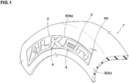
Fig. 1 is a partial perspective view of a tyre according to an embodiment of the present invention. -
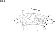
Fig. 2 is an enlarged partial perspective view of marks. -
Fig. 3A is a front view of one of the marks. -
Fig. 3B is a cross-sectional view of the one of the marks taken along A-A line ofFig. 3A . -
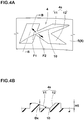
Fig. 4A is a front view of one of the marks according to another embodiment. -
Fig. 4B a cross-sectional view of the one of the marks according to another embodiment taken along B-B line ofFig. 4A . -
Fig. 5A is a diagram illustrating a diagonal line. -
Fig. 5B is a diagram illustrating a diagonal line. - An embodiment of the present invention will now be described below in detail.
- As shown in
Fig. 1 , a tyre 1 in this embodiment is provided with one or moremark indicating portions 3 in at least one ofsidewall portions 2. - Each of the
mark indicating portions 3 is provided with a reference surface (X) provided on a surface (2s) of a respective one of thesidewall portions 2 and one ormore marks 4 formed on the reference surface (x) in a concave manner. In this embodiment, each of themark indicating portions 3 is provided with abase portion 5 which projects stepwise from the surface (2s) of a respective one of thesidewall portions 2 at a constant height (H5) (that is, a top surface of the base portion is not inclined with respect to the surface (2s)) and a surface (5s) of thebase portion 5 forms the reference surface (X). - Each of the
marks 4 is a letter, a symbol, a figure, and the like for representing the manufacturer name, brand name, size, and the like of the tyre, and in this embodiment, a case is shown in which a brand name consisting of a plurality of themarks 4 is formed on the reference surface (X). - As shown in
Figs. 2 ,3A, and 3B , each of themarks 4 is formed in a concave shape recessed from the reference surface (X). A surface (4s) (bottom surface) of each of themarks 4 is divided into afirst surface portion 11 and asecond surface portion 12 by asection line 10 crossing the surface (4s). - The
section line 10 in this embodiment has a constant depth (Dx) from the reference surface (X). It is preferred that the depth (Dx) is equal to or less than the height (H5) of thebase portion 5 from the surface (2s) of a respective one of thesidewall portions 2 from the point of view of securing strength of thesidewall portions 2. Note that the depth (Dx) may vary in a length direction of thesection line 10. In this case, it is preferred that thesection line 10 is formed in an arcuate shape in which the depth (Dx) is decreased gradually and smoothly from a center in the length direction toward both ends thereof. - The
section line 10 in this embodiment extends in a tyre circumferential direction. Specifically, thesection line 10 is curved so as to extend in an arc shape centered on an axis of the tyre. In particular, it is preferred that thesection lines 10 of a plurality of themarks 4 which is arranged within onemark indicating portion 3 are positioned on one circumferential line around the axis of the tyre. - As shown in
Fig. 3A , in a case where thesection line 10 extends in the tyre circumferential direction, in a front view, it is preferred that a distance (La) in a tyre radial direction between an outermost end in the tyre radial direction of each of themarks 4 and thesection line 10 thereof is in a range of from 0.8 to 1.2 times a distance (Lb) in the tyre radial direction between an innermost end in the tyre radial direction of each of themarks 4 and thesection line 10 thereof. If it is out of this range, the balance between thefirst surface portion 11 and thesecond surface portion 12 is deteriorated, therefore, design property is deteriorated. - Each of the
first surface portion 11 and thesecond surface portion 12 is inclined in a direction in which a depth thereof from the reference surface (X) is decreased as it goes away from thesection line 10. - when the
section line 10 extends in the tyre circumferential direction, thefirst surface portion 11 and thesecond surface portion 12 are inclined in opposite directions to each other (upward and downward) with respect to the tyre radial direction. Thereby, irrespective of the positions on the surfaces (2s) of thesidewall portions 2 at which themarks 4 are arranged, the surfaces (4s) of themarks 4 reflect light, therefore, it is possible that the legibility is increased. Moreover, each of the surfaces (4s) is inclined in a V-shape, therefore, a change is given to the appearance of themarks 4, thereby, the stereoscopic effect is increased. Therefore, it is possible that the design property and the legibility are improved. - Each of the
first surface portion 11 and thesecond surface portion 12 can be formed as a flat surface. However, it can also be formed as a curved surface curved in a concave shape or a convex shape, for example. -
Fig. 4A is a front view of one of themarks 4 in another embodiment andFig. 4B is a cross-sectional view thereof taken along B-B line. In this example, when the one of themarks 4 is viewed from the front, thesection line 10 extends diagonally on the surface (4s) of the one of themarks 4. - Here, "extending diagonally" is defined as follows. As shown in
Figs. 5A and 5B , when the smallest parallelogram among parallelograms (including the rectangles) surrounding one of themarks 4 is defined as a parallelogram (A), extending diagonally means extending in a direction so as to connect between diagonal neighborhoods (B) of the parallelogram (A). Here, the parallelogram (A) includes an upper side (a1) and a lower side (a2) extending in the tyre circumferential direction. Further, each of the diagonal neighborhoods (B) means a range in which a distance from a respective one of diagonals (b) of the parallelogram (A) is 10% or less of a length of a diagonal line (c). It is preferred that thesection line 10 extends in a direction so as to connect between the diagonals (b). As shown inFig. 4A , thesection line 10 in this embodiment is formed in an arcuate curved line in a front view of each of themarks 4. However, it can also be formed in a straight line. - In a case where the
section line 10 is inclined toward upper right as in this embodiment (Fig. 4A ), thefirst surface portion 11 is inclined toward an upper left direction F1 and thesecond surface portion 12 is inclined toward a lower right direction F2. In other words, thefirst surface portion 11 and thesecond surface portion 12 are inclined with respect to both the tyre circumferential direction and the tyre radial direction. - Therefore, irrespective of the positions on the surfaces (2s) of the
sidewall portions 2 at which themarks 4 are arranged, the surfaces (4s) of themarks 4 reflect light, therefore, it is possible that the legibility is increased. Further, thefirst surface portion 11 and thesecond surface portion 12 have components that are inclined in opposite directions to each other with respect to the tyre circumferential direction, therefore, the reflecting surfaces appear changing and sparkling when the tyre rotates. Thereby, it is possible that the visibility is further improved as compared with the case where thesection line 10 extends in the tyre circumferential direction. - Although not shown, in a cross section taken orthogonal to the
section line 10, it is preferred that an inclination angle of thefirst surface portion 11 with respect to the reference surface (X) is the same as an inclination angle of thesecond surface portion 12 with respect to the reference surface (X) from a point of view of the design property. Further, from the point of view of the design property, it is preferred that a ratio (J1/J2) between an area (J1) of thefirst surface portion 11 and an area (J2) of thesecond surface portion 12 is in a range of from 0.7 to 1.3 when the surface (4s) is viewed from the front. - In each of the
mark indicating portions 3, it is possible that themarks 4 are directly formed on the surface (2s) of a respective one of thesidewall portions 2 without having thebase portion 5 formed thereon. In this case, the surface (2s) of thesidewall portion 2 forms the reference surface (X). In this case, in order to distinguish themark indicating portions 3 from other portions, it is preferred that the surface (2s) of each of thesidewall portions 2 is provided with a rib and the like having a small height and surrounding each of themark indicating portions 3. - while detailed description has been made of the tyre as especially preferred embodiments of the present invention, the present invention can be embodied in various forms without being limited to the illustrated embodiments.
- Tyres provided with the mark indicating portions on the surface of the sidewall portions were made by way of test according to the specifications listed in Table 1, and then the legibility of the marks was compared.
- In Reference 1, no section line is provided and each of the surfaces (bottom surfaces) of the marks are formed as a flat surface.
- In Example 1, the section line extends in the tyre circumferential direction, therefore, the first surface portion and the second surface portion are inclined in the tyre radial direction in a V-shape. Further, in Example 2, in each of the marks, the section line extends diagonally, therefore, the first surface portion is inclined in the direction F1 and the second surface portion is inclined in the direction F2 (shown in
Fig. 4A ) so as to form a V-shape. Note that a depth of each of the marks of the Reference 1 and each of the depths (Dx) of the section lines in the Examples 1 and 2 are equal to the height (H5) of each of the base portions. Further, in a plan view, each of the section lines is formed in an arcuate curved line. Furthermore, in each of the marks, the first surface portion and the second surface portion which are divided by the section line are each formed as a flat surface. - The legibility was evaluated by a visual observation and the evaluation is indicated by an index based on the Reference 1 being 100, wherein a larger numerical value is better.
Table 1 Ref.1 Ex.1 Ex.2 < Mark indicating portion > Base portion Present Mark Present (concave) • Presence or Absence of Section line Absence Presence • Direction of Section line - Tyre circumferential direction diagonal direction • Inclination of Surface Not inclined Inclined (v-shape) Legibility 100 110 115 - As shown in Table 1, it was confirmed that the tyres as the Examples showed excellent legibility of the marks.
Claims (7)
- A tyre comprising a sidewall portion provided with a mark indicating portion having one or more marks, wherein
the mark indicating portion comprises a reference surface provided on a surface of the sidewall portion and the one or more marks formed on the reference surface in a concave manner,
a surface of the or each mark is divided into a first surface portion and a second surface portion by a section line crossing the surface of the or each mark, and
each of the first surface portion and the second surface portion is inclined in a direction in which a depth thereof from the reference surface is decreased as it goes away from the section line. - The tyre according to claim 1, wherein
the section line extends on the surface of the or each mark in a tyre circumferential direction. - The tyre according to claim 1, wherein
the section line extends diagonally on the surface of the or each mark. - The tyre according to any one of claims 1 to 3, wherein
a depth of the section line from the reference surface is constant. - The tyre according to any one of claims 1 to 4, wherein
the section line is a straight line or an arcuate curved line. - The tyre according to any one of claims 1 to 5, wherein
each of the first surface portion and the second surface portion is a flat surface or a concave or convex curved surface. - The tyre according to any one of claims 1 to 6, wherein
the mark indicating portion is provided with a base portion projecting from the surface of the sidewall portion at a constant height, and
a surface of the base portion forms the reference surface.
Applications Claiming Priority (1)
| Application Number | Priority Date | Filing Date | Title |
|---|---|---|---|
| JP2018058490A JP7040200B2 (en) | 2018-03-26 | 2018-03-26 | tire |
Publications (2)
| Publication Number | Publication Date |
|---|---|
| EP3546252A1 true EP3546252A1 (en) | 2019-10-02 |
| EP3546252B1 EP3546252B1 (en) | 2020-09-23 |
Family
ID=65686741
Family Applications (1)
| Application Number | Title | Priority Date | Filing Date |
|---|---|---|---|
| EP19160607.8A Active EP3546252B1 (en) | 2018-03-26 | 2019-03-04 | Tyre |
Country Status (3)
| Country | Link |
|---|---|
| US (1) | US20190291517A1 (en) |
| EP (1) | EP3546252B1 (en) |
| JP (1) | JP7040200B2 (en) |
Citations (5)
| Publication number | Priority date | Publication date | Assignee | Title |
|---|---|---|---|---|
| JP3007825B2 (en) * | 1995-09-28 | 2000-02-07 | 住友ゴム工業株式会社 | Pneumatic tire |
| JP2008273505A (en) * | 2007-04-05 | 2008-11-13 | Toyo Tire & Rubber Co Ltd | Pneumatic tire |
| US20110253278A1 (en) * | 2008-06-17 | 2011-10-20 | The Yokohama Rubber Co., Ltd. | Pneumatic tire |
| JP2013129233A (en) | 2011-12-20 | 2013-07-04 | Yokohama Rubber Co Ltd:The | Pneumatic tire and method for manufacturing the same |
| EP2740613A1 (en) * | 2011-08-04 | 2014-06-11 | Bridgestone Corporation | Tire |
Family Cites Families (5)
| Publication number | Priority date | Publication date | Assignee | Title |
|---|---|---|---|---|
| LU80687A1 (en) * | 1977-12-23 | 1979-04-13 | Dunlop Ltd | SHALLOW GROUND PATTERNS ON TIRE SIDES |
| CA2056572A1 (en) * | 1990-12-10 | 1992-06-11 | Aristides E. Makris | Character for a tire |
| US20080283169A1 (en) * | 2007-02-22 | 2008-11-20 | Toyo Tire & Rubber Co., Ltd. | Pneumatic Tire |
| US20120060994A1 (en) * | 2009-06-01 | 2012-03-15 | Satoshi Hayashi | Pneumatic tire |
| JP5520334B2 (en) * | 2012-04-04 | 2014-06-11 | 住友ゴム工業株式会社 | Pneumatic tire |
-
2018
- 2018-03-26 JP JP2018058490A patent/JP7040200B2/en active Active
-
2019
- 2019-03-04 EP EP19160607.8A patent/EP3546252B1/en active Active
- 2019-03-05 US US16/292,686 patent/US20190291517A1/en not_active Abandoned
Patent Citations (5)
| Publication number | Priority date | Publication date | Assignee | Title |
|---|---|---|---|---|
| JP3007825B2 (en) * | 1995-09-28 | 2000-02-07 | 住友ゴム工業株式会社 | Pneumatic tire |
| JP2008273505A (en) * | 2007-04-05 | 2008-11-13 | Toyo Tire & Rubber Co Ltd | Pneumatic tire |
| US20110253278A1 (en) * | 2008-06-17 | 2011-10-20 | The Yokohama Rubber Co., Ltd. | Pneumatic tire |
| EP2740613A1 (en) * | 2011-08-04 | 2014-06-11 | Bridgestone Corporation | Tire |
| JP2013129233A (en) | 2011-12-20 | 2013-07-04 | Yokohama Rubber Co Ltd:The | Pneumatic tire and method for manufacturing the same |
Also Published As
| Publication number | Publication date |
|---|---|
| JP7040200B2 (en) | 2022-03-23 |
| JP2019167067A (en) | 2019-10-03 |
| US20190291517A1 (en) | 2019-09-26 |
| EP3546252B1 (en) | 2020-09-23 |
Similar Documents
| Publication | Publication Date | Title |
|---|---|---|
| EP3546251B1 (en) | Tyre | |
| JP3072921B2 (en) | Pneumatic tire | |
| EP3533633B1 (en) | Tyre | |
| US20070034312A1 (en) | Vehicle tire | |
| JP6747932B2 (en) | Pneumatic tire | |
| JP5824467B2 (en) | Pneumatic tire | |
| KR20090088934A (en) | Tire | |
| WO2008075544A1 (en) | Tire | |
| JPH1086615A (en) | Pneumatic tire | |
| EP3546252B1 (en) | Tyre | |
| US11072207B2 (en) | Tire | |
| EP3511180B1 (en) | Tyre | |
| CN107206851B (en) | Pneumatic tire | |
| JP5675241B2 (en) | tire | |
| EP3533634B1 (en) | Tyre | |
| EP3533635B1 (en) | Tyre | |
| EP3533636B1 (en) | Tyre | |
| JP7172538B2 (en) | tire | |
| EP3533637B1 (en) | Tyre | |
| EP3666555A1 (en) | Tire | |
| US20240278603A1 (en) | Pneumatic tire |
Legal Events
| Date | Code | Title | Description |
|---|---|---|---|
| PUAI | Public reference made under article 153(3) epc to a published international application that has entered the european phase |
Free format text: ORIGINAL CODE: 0009012 |
|
| STAA | Information on the status of an ep patent application or granted ep patent |
Free format text: STATUS: THE APPLICATION HAS BEEN PUBLISHED |
|
| AK | Designated contracting states |
Kind code of ref document: A1 Designated state(s): AL AT BE BG CH CY CZ DE DK EE ES FI FR GB GR HR HU IE IS IT LI LT LU LV MC MK MT NL NO PL PT RO RS SE SI SK SM TR |
|
| AX | Request for extension of the european patent |
Extension state: BA ME |
|
| STAA | Information on the status of an ep patent application or granted ep patent |
Free format text: STATUS: REQUEST FOR EXAMINATION WAS MADE |
|
| 17P | Request for examination filed |
Effective date: 20200207 |
|
| RBV | Designated contracting states (corrected) |
Designated state(s): AL AT BE BG CH CY CZ DE DK EE ES FI FR GB GR HR HU IE IS IT LI LT LU LV MC MK MT NL NO PL PT RO RS SE SI SK SM TR |
|
| GRAP | Despatch of communication of intention to grant a patent |
Free format text: ORIGINAL CODE: EPIDOSNIGR1 |
|
| STAA | Information on the status of an ep patent application or granted ep patent |
Free format text: STATUS: GRANT OF PATENT IS INTENDED |
|
| INTG | Intention to grant announced |
Effective date: 20200423 |
|
| GRAS | Grant fee paid |
Free format text: ORIGINAL CODE: EPIDOSNIGR3 |
|
| GRAA | (expected) grant |
Free format text: ORIGINAL CODE: 0009210 |
|
| STAA | Information on the status of an ep patent application or granted ep patent |
Free format text: STATUS: THE PATENT HAS BEEN GRANTED |
|
| AK | Designated contracting states |
Kind code of ref document: B1 Designated state(s): AL AT BE BG CH CY CZ DE DK EE ES FI FR GB GR HR HU IE IS IT LI LT LU LV MC MK MT NL NO PL PT RO RS SE SI SK SM TR |
|
| REG | Reference to a national code |
Ref country code: GB Ref legal event code: FG4D |
|
| REG | Reference to a national code |
Ref country code: CH Ref legal event code: EP |
|
| REG | Reference to a national code |
Ref country code: IE Ref legal event code: FG4D |
|
| REG | Reference to a national code |
Ref country code: DE Ref legal event code: R096 Ref document number: 602019000731 Country of ref document: DE Ref country code: AT Ref legal event code: REF Ref document number: 1316035 Country of ref document: AT Kind code of ref document: T Effective date: 20201015 |
|
| PG25 | Lapsed in a contracting state [announced via postgrant information from national office to epo] |
Ref country code: NO Free format text: LAPSE BECAUSE OF FAILURE TO SUBMIT A TRANSLATION OF THE DESCRIPTION OR TO PAY THE FEE WITHIN THE PRESCRIBED TIME-LIMIT Effective date: 20201223 Ref country code: GR Free format text: LAPSE BECAUSE OF FAILURE TO SUBMIT A TRANSLATION OF THE DESCRIPTION OR TO PAY THE FEE WITHIN THE PRESCRIBED TIME-LIMIT Effective date: 20201224 Ref country code: FI Free format text: LAPSE BECAUSE OF FAILURE TO SUBMIT A TRANSLATION OF THE DESCRIPTION OR TO PAY THE FEE WITHIN THE PRESCRIBED TIME-LIMIT Effective date: 20200923 Ref country code: SE Free format text: LAPSE BECAUSE OF FAILURE TO SUBMIT A TRANSLATION OF THE DESCRIPTION OR TO PAY THE FEE WITHIN THE PRESCRIBED TIME-LIMIT Effective date: 20200923 Ref country code: HR Free format text: LAPSE BECAUSE OF FAILURE TO SUBMIT A TRANSLATION OF THE DESCRIPTION OR TO PAY THE FEE WITHIN THE PRESCRIBED TIME-LIMIT Effective date: 20200923 Ref country code: BG Free format text: LAPSE BECAUSE OF FAILURE TO SUBMIT A TRANSLATION OF THE DESCRIPTION OR TO PAY THE FEE WITHIN THE PRESCRIBED TIME-LIMIT Effective date: 20201223 |
|
| REG | Reference to a national code |
Ref country code: AT Ref legal event code: MK05 Ref document number: 1316035 Country of ref document: AT Kind code of ref document: T Effective date: 20200923 |
|
| PG25 | Lapsed in a contracting state [announced via postgrant information from national office to epo] |
Ref country code: LV Free format text: LAPSE BECAUSE OF FAILURE TO SUBMIT A TRANSLATION OF THE DESCRIPTION OR TO PAY THE FEE WITHIN THE PRESCRIBED TIME-LIMIT Effective date: 20200923 Ref country code: RS Free format text: LAPSE BECAUSE OF FAILURE TO SUBMIT A TRANSLATION OF THE DESCRIPTION OR TO PAY THE FEE WITHIN THE PRESCRIBED TIME-LIMIT Effective date: 20200923 |
|
| REG | Reference to a national code |
Ref country code: NL Ref legal event code: MP Effective date: 20200923 |
|
| REG | Reference to a national code |
Ref country code: LT Ref legal event code: MG4D |
|
| PG25 | Lapsed in a contracting state [announced via postgrant information from national office to epo] |
Ref country code: EE Free format text: LAPSE BECAUSE OF FAILURE TO SUBMIT A TRANSLATION OF THE DESCRIPTION OR TO PAY THE FEE WITHIN THE PRESCRIBED TIME-LIMIT Effective date: 20200923 Ref country code: RO Free format text: LAPSE BECAUSE OF FAILURE TO SUBMIT A TRANSLATION OF THE DESCRIPTION OR TO PAY THE FEE WITHIN THE PRESCRIBED TIME-LIMIT Effective date: 20200923 Ref country code: PT Free format text: LAPSE BECAUSE OF FAILURE TO SUBMIT A TRANSLATION OF THE DESCRIPTION OR TO PAY THE FEE WITHIN THE PRESCRIBED TIME-LIMIT Effective date: 20210125 Ref country code: CZ Free format text: LAPSE BECAUSE OF FAILURE TO SUBMIT A TRANSLATION OF THE DESCRIPTION OR TO PAY THE FEE WITHIN THE PRESCRIBED TIME-LIMIT Effective date: 20200923 Ref country code: LT Free format text: LAPSE BECAUSE OF FAILURE TO SUBMIT A TRANSLATION OF THE DESCRIPTION OR TO PAY THE FEE WITHIN THE PRESCRIBED TIME-LIMIT Effective date: 20200923 Ref country code: SM Free format text: LAPSE BECAUSE OF FAILURE TO SUBMIT A TRANSLATION OF THE DESCRIPTION OR TO PAY THE FEE WITHIN THE PRESCRIBED TIME-LIMIT Effective date: 20200923 |
|
| PG25 | Lapsed in a contracting state [announced via postgrant information from national office to epo] |
Ref country code: ES Free format text: LAPSE BECAUSE OF FAILURE TO SUBMIT A TRANSLATION OF THE DESCRIPTION OR TO PAY THE FEE WITHIN THE PRESCRIBED TIME-LIMIT Effective date: 20200923 Ref country code: AL Free format text: LAPSE BECAUSE OF FAILURE TO SUBMIT A TRANSLATION OF THE DESCRIPTION OR TO PAY THE FEE WITHIN THE PRESCRIBED TIME-LIMIT Effective date: 20200923 Ref country code: AT Free format text: LAPSE BECAUSE OF FAILURE TO SUBMIT A TRANSLATION OF THE DESCRIPTION OR TO PAY THE FEE WITHIN THE PRESCRIBED TIME-LIMIT Effective date: 20200923 Ref country code: IS Free format text: LAPSE BECAUSE OF FAILURE TO SUBMIT A TRANSLATION OF THE DESCRIPTION OR TO PAY THE FEE WITHIN THE PRESCRIBED TIME-LIMIT Effective date: 20210123 Ref country code: PL Free format text: LAPSE BECAUSE OF FAILURE TO SUBMIT A TRANSLATION OF THE DESCRIPTION OR TO PAY THE FEE WITHIN THE PRESCRIBED TIME-LIMIT Effective date: 20200923 |
|
| REG | Reference to a national code |
Ref country code: DE Ref legal event code: R097 Ref document number: 602019000731 Country of ref document: DE |
|
| PG25 | Lapsed in a contracting state [announced via postgrant information from national office to epo] |
Ref country code: SK Free format text: LAPSE BECAUSE OF FAILURE TO SUBMIT A TRANSLATION OF THE DESCRIPTION OR TO PAY THE FEE WITHIN THE PRESCRIBED TIME-LIMIT Effective date: 20200923 |
|
| PLBE | No opposition filed within time limit |
Free format text: ORIGINAL CODE: 0009261 |
|
| STAA | Information on the status of an ep patent application or granted ep patent |
Free format text: STATUS: NO OPPOSITION FILED WITHIN TIME LIMIT |
|
| PG25 | Lapsed in a contracting state [announced via postgrant information from national office to epo] |
Ref country code: SI Free format text: LAPSE BECAUSE OF FAILURE TO SUBMIT A TRANSLATION OF THE DESCRIPTION OR TO PAY THE FEE WITHIN THE PRESCRIBED TIME-LIMIT Effective date: 20200923 Ref country code: DK Free format text: LAPSE BECAUSE OF FAILURE TO SUBMIT A TRANSLATION OF THE DESCRIPTION OR TO PAY THE FEE WITHIN THE PRESCRIBED TIME-LIMIT Effective date: 20200923 |
|
| 26N | No opposition filed |
Effective date: 20210624 |
|
| PG25 | Lapsed in a contracting state [announced via postgrant information from national office to epo] |
Ref country code: MC Free format text: LAPSE BECAUSE OF FAILURE TO SUBMIT A TRANSLATION OF THE DESCRIPTION OR TO PAY THE FEE WITHIN THE PRESCRIBED TIME-LIMIT Effective date: 20200923 Ref country code: IT Free format text: LAPSE BECAUSE OF FAILURE TO SUBMIT A TRANSLATION OF THE DESCRIPTION OR TO PAY THE FEE WITHIN THE PRESCRIBED TIME-LIMIT Effective date: 20200923 |
|
| REG | Reference to a national code |
Ref country code: BE Ref legal event code: MM Effective date: 20210331 |
|
| PG25 | Lapsed in a contracting state [announced via postgrant information from national office to epo] |
Ref country code: LU Free format text: LAPSE BECAUSE OF NON-PAYMENT OF DUE FEES Effective date: 20210304 Ref country code: IE Free format text: LAPSE BECAUSE OF NON-PAYMENT OF DUE FEES Effective date: 20210304 |
|
| PG25 | Lapsed in a contracting state [announced via postgrant information from national office to epo] |
Ref country code: BE Free format text: LAPSE BECAUSE OF NON-PAYMENT OF DUE FEES Effective date: 20210331 |
|
| REG | Reference to a national code |
Ref country code: CH Ref legal event code: PL |
|
| PG25 | Lapsed in a contracting state [announced via postgrant information from national office to epo] |
Ref country code: LI Free format text: LAPSE BECAUSE OF NON-PAYMENT OF DUE FEES Effective date: 20220331 Ref country code: CH Free format text: LAPSE BECAUSE OF NON-PAYMENT OF DUE FEES Effective date: 20220331 |
|
| P01 | Opt-out of the competence of the unified patent court (upc) registered |
Effective date: 20230510 |
|
| PG25 | Lapsed in a contracting state [announced via postgrant information from national office to epo] |
Ref country code: NL Free format text: LAPSE BECAUSE OF NON-PAYMENT OF DUE FEES Effective date: 20200923 Ref country code: CY Free format text: LAPSE BECAUSE OF FAILURE TO SUBMIT A TRANSLATION OF THE DESCRIPTION OR TO PAY THE FEE WITHIN THE PRESCRIBED TIME-LIMIT Effective date: 20200923 |
|
| PG25 | Lapsed in a contracting state [announced via postgrant information from national office to epo] |
Ref country code: HU Free format text: LAPSE BECAUSE OF FAILURE TO SUBMIT A TRANSLATION OF THE DESCRIPTION OR TO PAY THE FEE WITHIN THE PRESCRIBED TIME-LIMIT; INVALID AB INITIO Effective date: 20190304 |
|
| GBPC | Gb: european patent ceased through non-payment of renewal fee |
Effective date: 20230304 |
|
| PG25 | Lapsed in a contracting state [announced via postgrant information from national office to epo] |
Ref country code: GB Free format text: LAPSE BECAUSE OF NON-PAYMENT OF DUE FEES Effective date: 20230304 |
|
| PG25 | Lapsed in a contracting state [announced via postgrant information from national office to epo] |
Ref country code: GB Free format text: LAPSE BECAUSE OF NON-PAYMENT OF DUE FEES Effective date: 20230304 |
|
| PG25 | Lapsed in a contracting state [announced via postgrant information from national office to epo] |
Ref country code: MK Free format text: LAPSE BECAUSE OF FAILURE TO SUBMIT A TRANSLATION OF THE DESCRIPTION OR TO PAY THE FEE WITHIN THE PRESCRIBED TIME-LIMIT Effective date: 20200923 |
|
| PGFP | Annual fee paid to national office [announced via postgrant information from national office to epo] |
Ref country code: DE Payment date: 20240130 Year of fee payment: 6 |
|
| PGFP | Annual fee paid to national office [announced via postgrant information from national office to epo] |
Ref country code: FR Payment date: 20240213 Year of fee payment: 6 |
|
| PG25 | Lapsed in a contracting state [announced via postgrant information from national office to epo] |
Ref country code: TR Free format text: LAPSE BECAUSE OF FAILURE TO SUBMIT A TRANSLATION OF THE DESCRIPTION OR TO PAY THE FEE WITHIN THE PRESCRIBED TIME-LIMIT Effective date: 20200923 |