EP3546233A1 - Liquid discharge apparatus and liquid discharge method - Google Patents
Liquid discharge apparatus and liquid discharge method Download PDFInfo
- Publication number
- EP3546233A1 EP3546233A1 EP19163928.5A EP19163928A EP3546233A1 EP 3546233 A1 EP3546233 A1 EP 3546233A1 EP 19163928 A EP19163928 A EP 19163928A EP 3546233 A1 EP3546233 A1 EP 3546233A1
- Authority
- EP
- European Patent Office
- Prior art keywords
- liquid
- liquid discharge
- stimulation
- surface roughness
- amount
- Prior art date
- Legal status (The legal status is an assumption and is not a legal conclusion. Google has not performed a legal analysis and makes no representation as to the accuracy of the status listed.)
- Withdrawn
Links
Images



Classifications
-
- B—PERFORMING OPERATIONS; TRANSPORTING
- B41—PRINTING; LINING MACHINES; TYPEWRITERS; STAMPS
- B41J—TYPEWRITERS; SELECTIVE PRINTING MECHANISMS, i.e. MECHANISMS PRINTING OTHERWISE THAN FROM A FORME; CORRECTION OF TYPOGRAPHICAL ERRORS
- B41J2/00—Typewriters or selective printing mechanisms characterised by the printing or marking process for which they are designed
- B41J2/005—Typewriters or selective printing mechanisms characterised by the printing or marking process for which they are designed characterised by bringing liquid or particles selectively into contact with a printing material
- B41J2/01—Ink jet
-
- B—PERFORMING OPERATIONS; TRANSPORTING
- B29—WORKING OF PLASTICS; WORKING OF SUBSTANCES IN A PLASTIC STATE IN GENERAL
- B29C—SHAPING OR JOINING OF PLASTICS; SHAPING OF MATERIAL IN A PLASTIC STATE, NOT OTHERWISE PROVIDED FOR; AFTER-TREATMENT OF THE SHAPED PRODUCTS, e.g. REPAIRING
- B29C64/00—Additive manufacturing, i.e. manufacturing of three-dimensional [3D] objects by additive deposition, additive agglomeration or additive layering, e.g. by 3D printing, stereolithography or selective laser sintering
- B29C64/10—Processes of additive manufacturing
- B29C64/106—Processes of additive manufacturing using only liquids or viscous materials, e.g. depositing a continuous bead of viscous material
- B29C64/112—Processes of additive manufacturing using only liquids or viscous materials, e.g. depositing a continuous bead of viscous material using individual droplets, e.g. from jetting heads
-
- B—PERFORMING OPERATIONS; TRANSPORTING
- B29—WORKING OF PLASTICS; WORKING OF SUBSTANCES IN A PLASTIC STATE IN GENERAL
- B29C—SHAPING OR JOINING OF PLASTICS; SHAPING OF MATERIAL IN A PLASTIC STATE, NOT OTHERWISE PROVIDED FOR; AFTER-TREATMENT OF THE SHAPED PRODUCTS, e.g. REPAIRING
- B29C64/00—Additive manufacturing, i.e. manufacturing of three-dimensional [3D] objects by additive deposition, additive agglomeration or additive layering, e.g. by 3D printing, stereolithography or selective laser sintering
- B29C64/30—Auxiliary operations or equipment
- B29C64/386—Data acquisition or data processing for additive manufacturing
- B29C64/393—Data acquisition or data processing for additive manufacturing for controlling or regulating additive manufacturing processes
-
- B—PERFORMING OPERATIONS; TRANSPORTING
- B33—ADDITIVE MANUFACTURING TECHNOLOGY
- B33Y—ADDITIVE MANUFACTURING, i.e. MANUFACTURING OF THREE-DIMENSIONAL [3D] OBJECTS BY ADDITIVE DEPOSITION, ADDITIVE AGGLOMERATION OR ADDITIVE LAYERING, e.g. BY 3D PRINTING, STEREOLITHOGRAPHY OR SELECTIVE LASER SINTERING
- B33Y10/00—Processes of additive manufacturing
-
- B—PERFORMING OPERATIONS; TRANSPORTING
- B33—ADDITIVE MANUFACTURING TECHNOLOGY
- B33Y—ADDITIVE MANUFACTURING, i.e. MANUFACTURING OF THREE-DIMENSIONAL [3D] OBJECTS BY ADDITIVE DEPOSITION, ADDITIVE AGGLOMERATION OR ADDITIVE LAYERING, e.g. BY 3D PRINTING, STEREOLITHOGRAPHY OR SELECTIVE LASER SINTERING
- B33Y30/00—Apparatus for additive manufacturing; Details thereof or accessories therefor
-
- B—PERFORMING OPERATIONS; TRANSPORTING
- B33—ADDITIVE MANUFACTURING TECHNOLOGY
- B33Y—ADDITIVE MANUFACTURING, i.e. MANUFACTURING OF THREE-DIMENSIONAL [3D] OBJECTS BY ADDITIVE DEPOSITION, ADDITIVE AGGLOMERATION OR ADDITIVE LAYERING, e.g. BY 3D PRINTING, STEREOLITHOGRAPHY OR SELECTIVE LASER SINTERING
- B33Y50/00—Data acquisition or data processing for additive manufacturing
- B33Y50/02—Data acquisition or data processing for additive manufacturing for controlling or regulating additive manufacturing processes
-
- B—PERFORMING OPERATIONS; TRANSPORTING
- B41—PRINTING; LINING MACHINES; TYPEWRITERS; STAMPS
- B41J—TYPEWRITERS; SELECTIVE PRINTING MECHANISMS, i.e. MECHANISMS PRINTING OTHERWISE THAN FROM A FORME; CORRECTION OF TYPOGRAPHICAL ERRORS
- B41J11/00—Devices or arrangements of selective printing mechanisms, e.g. ink-jet printers or thermal printers, for supporting or handling copy material in sheet or web form
- B41J11/0015—Devices or arrangements of selective printing mechanisms, e.g. ink-jet printers or thermal printers, for supporting or handling copy material in sheet or web form for treating before, during or after printing or for uniform coating or laminating the copy material before or after printing
- B41J11/002—Curing or drying the ink on the copy materials, e.g. by heating or irradiating
-
- B—PERFORMING OPERATIONS; TRANSPORTING
- B41—PRINTING; LINING MACHINES; TYPEWRITERS; STAMPS
- B41J—TYPEWRITERS; SELECTIVE PRINTING MECHANISMS, i.e. MECHANISMS PRINTING OTHERWISE THAN FROM A FORME; CORRECTION OF TYPOGRAPHICAL ERRORS
- B41J11/00—Devices or arrangements of selective printing mechanisms, e.g. ink-jet printers or thermal printers, for supporting or handling copy material in sheet or web form
- B41J11/0015—Devices or arrangements of selective printing mechanisms, e.g. ink-jet printers or thermal printers, for supporting or handling copy material in sheet or web form for treating before, during or after printing or for uniform coating or laminating the copy material before or after printing
- B41J11/002—Curing or drying the ink on the copy materials, e.g. by heating or irradiating
- B41J11/0021—Curing or drying the ink on the copy materials, e.g. by heating or irradiating using irradiation
- B41J11/00212—Controlling the irradiation means, e.g. image-based controlling of the irradiation zone or control of the duration or intensity of the irradiation
-
- B—PERFORMING OPERATIONS; TRANSPORTING
- B41—PRINTING; LINING MACHINES; TYPEWRITERS; STAMPS
- B41J—TYPEWRITERS; SELECTIVE PRINTING MECHANISMS, i.e. MECHANISMS PRINTING OTHERWISE THAN FROM A FORME; CORRECTION OF TYPOGRAPHICAL ERRORS
- B41J11/00—Devices or arrangements of selective printing mechanisms, e.g. ink-jet printers or thermal printers, for supporting or handling copy material in sheet or web form
- B41J11/0015—Devices or arrangements of selective printing mechanisms, e.g. ink-jet printers or thermal printers, for supporting or handling copy material in sheet or web form for treating before, during or after printing or for uniform coating or laminating the copy material before or after printing
- B41J11/002—Curing or drying the ink on the copy materials, e.g. by heating or irradiating
- B41J11/0021—Curing or drying the ink on the copy materials, e.g. by heating or irradiating using irradiation
- B41J11/00214—Curing or drying the ink on the copy materials, e.g. by heating or irradiating using irradiation using UV radiation
-
- G—PHYSICS
- G01—MEASURING; TESTING
- G01B—MEASURING LENGTH, THICKNESS OR SIMILAR LINEAR DIMENSIONS; MEASURING ANGLES; MEASURING AREAS; MEASURING IRREGULARITIES OF SURFACES OR CONTOURS
- G01B11/00—Measuring arrangements characterised by the use of optical techniques
- G01B11/30—Measuring arrangements characterised by the use of optical techniques for measuring roughness or irregularity of surfaces
Definitions
- the present invention relates to a liquid discharge apparatus and a liquid discharge method.
- an image forming method for forming a three-dimensional image or a three-dimensional object by laminating layers formed by discharging an ink and drying or curing the ink is known.
- a "formed object” includes a three-dimensional image and a three-dimensional object.
- a photocurable ink for example, a ultraviolet (UV) ink
- a photocurable ink for example, a ultraviolet (UV) ink
- UV ultraviolet
- a medium image-formed object
- UV ink dot on the medium is irradiated with light and cured, and the UV ink dot is thereby fixed onto the medium to form a formed object.
- JP-2013-059868-A discloses a technique of changing the position of an irradiation apparatus in a sub-scanning direction by mode selection and controlling time discharge of an ink to curing of the ink to control surface roughness of a formed object to selectively execute mat printing or gross printing.
- a mode for mat printing and gloss printing is selected and mat printing and gloss printing are performed as separate jobs, and an image in which regions having different values of surface roughness are disposed in the same plane of a formed object within a single job cannot be formed.
- An object of the present invention is to properly control surface roughness for each region that can be stimulated by a curing device in the same plane of a three-dimensional formed object with a simple configuration without an increase in size of an apparatus or reduction in productivity.
- a liquid discharge apparatus includes a liquid discharge device, an acquisition unit, a stimulation-amount setting unit, and a curing device.
- the liquid discharge device is configured to discharge a liquid having a curing degree variable by a stimulation amount while relatively moving with respect to a recording medium.
- the acquisition unit is configured to acquire surface roughness information indicating glossiness of a formed object formed on the recording medium.
- the stimulation-amount setting unit is configured to set a stimulation amount for the liquid based on the surface roughness information.
- the curing device is configured to stimulate the liquid discharged by the liquid discharge device based on the stimulation amount set by the stimulation-amount setting unit to cure the liquid.
- the stimulation-amount setting unit is configured to set, based on the surface roughness information, the stimulation amount for each region that can be stimulated by the curing device in a same plane of the formed object.
- a liquid discharge method is to be executed by a liquid discharge apparatus.
- the method includes discharging a liquid having a curing degree variable by a stimulation amount while relatively moving with respect to a recording medium, acquiring surface roughness information indicating glossiness of a formed object formed on the recording medium, setting a stimulation amount for the liquid based on the surface roughness information, and stimulating the liquid discharged by the discharging based on the stimulation amount set by the setting to cure the liquid.
- the setting sets, based on the surface roughness information, the stimulation amount for each region to be stimulated by the curing in a same plane of the formed object.
- the present invention by setting the stimulation amount for each region that can be stimulated by the curing device based on the surface roughness information, it is possible to properly control surface roughness for each region that can be stimulated by the curing device in the same plane of a three-dimensional formed object with a simpler configuration.
- FIG. 1 is a schematic configuration diagram illustrating an example of an image processing system 10 according to an embodiment.
- the image processing system 10 includes an image processing apparatus 12 and an image forming apparatus 30.
- the image processing apparatus 12 and the image forming apparatus 30 are communicably connected to each other.
- a "liquid discharge apparatus" in a broad sense includes any of the image processing system 10 including the image processing apparatus 12 and the image forming apparatus 30, the image processing apparatus 12 alone, and the image forming apparatus 30 alone.
- the image forming apparatus 30 includes a liquid discharge device 14, a movable stage 16, and a driving device 25.
- the liquid discharge device 14 is an inkjet system carriage including a plurality of heads 18 (recording heads) provided with a plurality of nozzles, and discharges a droplet from each of nozzles of the heads 18 to record a dot.
- the nozzles are disposed on a surface of the liquid discharge device 14 facing the movable stage 16.
- the droplet includes an ink droplet and an additional droplet.
- the ink droplet is a droplet of an ink including a coloring material used for image formation (color ink).
- the additional droplet is a droplet of a color not affecting an image.
- the additional droplet is, for example, white or transparent (clear ink).
- the additional droplet may have a similar color to the color of a support P which is an image-formed object.
- the support P is an image-formed object of an image formed by the ink droplet.
- the support P is, for example, a recording medium.
- the ink droplet and the additional droplet have stimulation-curability.
- the stimulation is, for example, light (ultraviolet ray, infrared ray, or the like), heat, or electricity.
- the ink droplet and the additional droplet are ultraviolet-curable will be described. Note that the ink droplet and the additional droplet are not limited to the ultraviolet-curable form.
- An irradiation device 22 is disposed on a surface of the liquid discharge device 14 facing the movable stage 16.
- the irradiation device 22 that functions as a curing device irradiates the support P with light having a wavelength for curing an ink droplet and an additional droplet discharged from the nozzles.
- the irradiation device 22 includes, for example, an ultraviolet light-emitting diode (UV-LED), and emits an ultraviolet ray.
- UV-LED ultraviolet light-emitting diode
- the irradiation device 22 makes the light amount (stimulation amount) of the LED variable, for example, using a pulse width modulation (PWM) system.
- PWM pulse width modulation
- the movable stage 16 holds the support P.
- the driving device 25 relatively moves the liquid discharge device 14 and the movable stage 16 in a vertical direction Z (in the direction of the arrow Z in FIG. 1 ), a main scanning direction X perpendicular to the vertical direction Z, and a sub-scanning direction Y perpendicular to the vertical direction Z and the main scanning direction X.
- a plane including the main scanning direction X and the sub-scanning direction Y corresponds to an XY plane along a surface of the movable stage 16 facing the liquid discharge device 14.
- the driving device 25 includes a first driving device 23 and a second driving device 24.
- the first driving device 23 moves the liquid discharge device 14 in the vertical direction Z, the main scanning direction X, and the sub-scanning direction Y.
- the second driving device 24 moves the movable stage 16 in the vertical direction Z, the main scanning direction X, and the sub-scanning direction Y.
- the image forming apparatus 30 may include either one of the first driving device 23 and the second driving device 24.
- the image forming apparatus 30 discharges an ultraviolet-curable droplet onto a predetermined region corresponding to image data, irradiate the droplet with an ultraviolet ray to cure the droplet, and sequentially laminates the droplets to perform three-dimensional modeling.
- the image forming apparatus 30 repeats a step of discharging an ultraviolet-curable droplet from the nozzle of the head 18 onto a predetermined region corresponding to image data on the support P, then irradiating the droplet with an ultraviolet ray from the adjacent irradiation device 22 to cure the droplet to form a first layer, then discharging an ultraviolet-curable droplet from the nozzle of the head 18 onto a predetermined region corresponding to image data, and irradiating the droplet with an ultraviolet ray from the adjacent irradiation device 22 to cure the droplet to form a second layer while lowering the movable stage 16 in accordance with the number of lamination, and thereby forms a three-dimensional formed object (protrusion).
- an ultraviolet-curable composition constituting the ultraviolet-curable ink will be exemplified.
- the ultraviolet-curable composition according to the present embodiment contains at least two monomers, a polymerization initiator, and an ultraviolet absorber.
- the at least two monomers include a monofunctional monomer and a polyfunctional monomer.
- the content of the polyfunctional monomer is 40% by mass or more with respect to the total amount of the monomers.
- the ultraviolet-curable composition further contains a coloring material, an organic solvent, and other components, if necessary.
- an ultraviolet-curable composition is applied onto the support P and irradiated with an ultraviolet ray having a wavelength of 395 nm, an illuminance of 2.5 W/cm 2 , and an irradiation dose of 1,000 mJ/cm 2 to be cured.
- an ultraviolet ray having a wavelength of 395 nm, an illuminance of 2.5 W/cm 2 , and an irradiation dose of 1,000 mJ/cm 2 to be cured.
- a ratio between a minimum value and a maximum value (minimum value/maximum value) in measurement of depth up to Martens hardness of 5.0 ⁇ m using a micro hardness meter is larger than 0.55.
- the hardness of a surface of a formed object varies depending on the irradiation light amount of the irradiation device 22. For example, in a case where an ultraviolet ray having a wavelength of 395 nm and an illuminance of 2.5 W/cm 2 is emitted, the hardness of a surface of a formed object at an irradiation dose of 300 mJ/cm 2 is lower than that an irradiation dose of 1,000 mJ/cm 2 . That is, the ink which is an ultraviolet-curable composition according to the present embodiment is a liquid having a curing degree variable by the light amount (stimulation amount) of an ultraviolet ray.
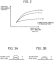
- FIG. 2 is a graph illustrating an example of a relationship between the irradiation light amount of a first layer and surface roughness of a second layer
- FIGS. 3A and 3B are diagrams illustrating a difference in a lamination state according to the irradiation light amount.
- FIG. 3A illustrates a case where the irradiation light amount of an ultraviolet ray by the irradiation device 22 is large
- FIG. 3B illustrates a case where the irradiation light amount of an ultraviolet ray by the irradiation device 22 is small.
- the irradiation light amount of an ultraviolet ray by the irradiation device 22 is small, the hardness of a surface of a formed object is low. Therefore, as illustrated in FIG. 3B , in a case where the irradiation light amount of an ultraviolet ray by the irradiation device 22 with respect to an ink droplet or an additional droplet in the first layer is small, surface tension of a formed object of the droplet or the additional droplet in the first layer is small. Therefore, an ink droplet or an additional droplet in the second layer spreads in a wet state. That is, as illustrated in FIG.
- the above-described tendency is more significant as time from landing of an ink droplet or an additional droplet to irradiation is shorter.
- FIG. 4 is a block diagram illustrating an example of the hardware configuration of the image processing apparatus 12.
- the image processing apparatus 12 includes an input device 130 for inputting data, a display device 131 such as a display, a communication device 132 for performing data communication, a central processing unit (CPU) 133 as a controller for controlling the entire apparatus, a random access memory (RAM) 134 used as a work area of the CPU 133, and a memory device 135 storing various programs and the like for operating the CPU 133.
- a display device 131 such as a display
- a communication device 132 for performing data communication
- a central processing unit (CPU) 133 as a controller for controlling the entire apparatus
- RAM random access memory
- memory device 135 storing various programs and the like for operating the CPU 133.
- Examples of the input device 130 include a keyboard including a cursor key, a numeric input key, and various function keys, and further include a mouse and a slice pad for selecting a key on a display screen of the display device 131.
- the input device 130 is a user interface for a user to give an operation instruction to the CPU 133 or to input data.
- Examples of the display device 131 include a cathode ray tube (CRT) and a liquid crystal display (LCD), and the display device 131 performs display corresponding to display data input from the CPU 133.
- the communication device 132 is for data communication with the outside, and is for performing data communication with the image forming apparatus 30 through a predetermined communication interface.
- the CPU 133 is a central control unit for controlling the entire apparatus according to a program stored in the memory device 135.
- the input device 130, the display device 131, the communication device 132, the RAM 134, and the memory device 135 are connected to the CPU 133.
- the CPU 133 controls data communication, reading of an application program by access to a memory, reading/writing of various kinds of data, data/command Input, display, and the like.
- the CPU 133 also transmits image data for forming an image based on image data input from the input device 130 and image data stored in the memory device 135 to the image forming apparatus 30 via the communication device 132.
- the RAM 134 includes a work memory for storing a specified program, an input instruction, input data, a processing result, and the like, and a display memory for temporarily storing display data to be displayed on a display screen of the display device 131.
- the memory device 135 stores various programs and data such as an OS program executable by the CPU 133 (for example, Microsoft's operating system Windows (registered trademark)) and a printer driver corresponding to the image forming apparatus 30.
- an OS program executable by the CPU 133 for example, Microsoft's operating system Windows (registered trademark)
- a printer driver corresponding to the image forming apparatus 30 for example, a printer driver corresponding to the image forming apparatus 30.
- examples of the memory device 135 include an optical, magnetic, and electrical recording media such as a hard disk, CD-ROM, and DVD-ROM.
- Various programs are stored in the memory device 135 in a data form readable by the CPU 133.
- the various programs may be recorded in the memory device 135 in advance or may be downloaded via a communication line such as the Internet and stored in the memory device 135.
- a program executed by the image processing apparatus 12 has a module configuration including the following functions.
- the CPU 133 of the image processing apparatus 12 reads a program from the memory device 135 or the like and executes the program. As a result, each module is loaded on the RAM 134, and the functions are exhibited.
- FIG. 5 is a block diagram illustrating a functional configuration of the image processing apparatus 12.
- the image processing apparatus 12 includes a main control unit 13 and a recording control unit 28.
- the main control unit 13 includes a data acquisition unit 12A, a data creating unit 12B, and a data output unit 12C.
- the data acquisition unit 12A, the data creating unit 12B, the data output unit 12C, and the recording control unit 28 are achieved by software, but the present invention is not limited thereto.
- the data acquisition unit 12A, the data creating unit 12B, the data output unit 12C, and the recording control unit 28 may be achieved by hardware such as an integrated circuit (IC), or may be achieved by using both software and hardware.
- IC integrated circuit
- the data acquisition unit 12A is an acquisition unit for acquiring image data and surface roughness information.
- the image data is information regarding the shape or color of an image to be formed.
- the surface roughness information may be information expressed by glossiness or smoothness.
- the data acquisition unit 12A may acquire the image data and the surface roughness information from an external device via the communication device 132 or may acquire the image data and the surface roughness from the memory device 135 disposed in the image processing apparatus 12.
- the data creating unit 12B performs predetermined data processing such as mask processing on the image data and the surface roughness information acquired by the data acquisition unit 12A.
- the data output unit 12C outputs the image data and the surface roughness information created by the data creating unit 12B to the image forming apparatus 30.
- the recording control unit 28 controls the liquid discharge device 14 and the driving device 25 of the image forming apparatus 30 so as to discharge a droplet 32 (see FIG. 6 ) corresponding to each pixel from the head 18 based on the image data created by the data output unit 12C.
- the recording control unit 28 functioning as a stimulation-amount setting unit controls the irradiation device 22 based on the surface roughness information. More particularly, the recording control unit 28 sets the light amount of an ultraviolet ray to be emitted for each irradiation region (unit area of a formed object formed on the support P) of the irradiation device 22 based on the surface roughness information.
- the recording control unit 28 includes, for example, a table in which the surface roughness information and the light amount of an ultraviolet ray are associated with each other.
- the image processing system 10 includes the image processing apparatus 12 and the image forming apparatus 30 that are communicably connected.
- the image processing apparatus 12 may be included in the image forming apparatus 30.
- the image forming apparatus 30 may include the recording control unit 28, and the recording control unit 28 may accept image data from the data output unit 12C of the image processing apparatus 12.
- the image forming apparatus 30 discharges an ink which is an ultraviolet-curable composition and forms an image by an optical modeling method for curing the ultraviolet-curable composition by irradiation with light.
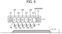
- FIG. 6 is a schematic diagram illustrating an example of the liquid discharge device 14 of the image forming apparatus 30.
- the liquid discharge device 14 in the image forming apparatus 30 is a carriage on which a plurality of nozzles 19 is arranged in a predetermined direction.
- Each of the nozzles 19 discharges an ink droplet, an additional droplet, or a mixed liquid of the ink droplet and the additional droplet as the droplet 32.
- the nozzles 19 and the configuration for discharging a droplet are similar to those of a known inkjet system.
- heads 18K, 18C, 18M, 18Y, 18W, and 18T are arranged in a predetermined direction.
- the heads 18 include nozzles 19K, 19C, 19M, 19Y, 19W, and 19T (referred to as nozzles 19 when these nozzles are not distinguished from each other) for discharging ink droplets, respectively.
- the nozzle 19K discharges a black ink droplet
- the nozzle 19C discharges a cyan ink droplet
- the nozzle 19M discharges a magenta ink droplet
- the nozzle 19Y discharges a yellow ink droplet
- the nozzle 19W discharges a white additional droplet
- the nozzle 19T discharges a transparent additional droplet.
- a dot 34 corresponding to the droplet 32 is formed on the support P, and an image 17 is formed.
- the droplets 32 are laminated and discharged, and the dots 34 are thereby laminated to form the three-dimensional image 17 as a formed object.
- the irradiation devices 22 are disposed at both ends in an arrangement direction of the heads 18K, 18C, 18M, 18Y, 18W, and 18T.
- the droplet 32 discharged from each of the nozzles 19 is irradiated with ultraviolet light by the irradiation device 22, and the droplet 32 is thereby cured.
- the irradiation device 22 is preferably disposed in the vicinity of the nozzle 19.
- the irradiation device 22 By disposing the irradiation device 22 in the vicinity of the nozzle 19, it is possible to shorten curing time from attachment of the droplet 32 discharged from the nozzle 19 to a side of the support P to curing of the droplet 32. Therefore, it is possible to form a higher definition image.
- the number of the irradiation devices 22 and the installation positions of the irradiation devices 22 are not limited to the form illustrated in FIG. 6 .
- FIG. 6 illustrates a case where each of the heads 18 discharges one color (one type) of liquid droplet 32, but the present invention is not limited thereto.
- each of the heads 18 may include two or more nozzles 19.
- the nozzle 19 may discharge a mixed droplet of a plurality of types of droplets 32.
- the color of an ink discharged from the liquid discharge device 14 is not limited to black, cyan, magenta, and yellow.
- the types of the droplet 32 discharged from the liquid discharge device 14 is not limited to six types (black, cyan, magenta, yellow, white, and transparent).
- the image forming apparatus 30 can form the dot 34 with the droplet 32 on the support P or laminate the dots 34.
- the support P may have a planar shape or a three-dimensional shape with irregularities or the like.
- the support P may be any of paper, coated paper, cardboard, OHP, a plastic film, prepreg, copper foil, polycarbonate, metal, glass, and the like.
- the image forming apparatus 30 sets the light amount of an ultraviolet ray to be emitted for each irradiation region of the irradiation device 22 based on surface roughness information under control of the recording control unit 28, and can thereby properly control surface roughness for each region that can be irradiated with the ultraviolet ray by the irradiation device 22 in the same plane of a three-dimensional formed object with a simpler configuration.
- FIG. 7 is a flowchart schematically illustrating the flow of the image forming process.
- the recording control unit 28 receives image data and surface roughness information of a first layer output from the data output unit 12C of the image processing apparatus 12 (step S1).
- the recording control unit 28 controls the liquid discharge device 14 and the driving device 25 of the image forming apparatus 30 so as to discharge the droplet 32 corresponding to each pixel from the head 18 based on the image data of the first layer (step S2).
- the recording control unit 28 sets the light amount of an ultraviolet ray to be emitted for each irradiation region (unit area of a formed object formed on the support P) of the irradiation device 22 based on the surface roughness information of the first layer and controls the irradiation device 22 (step S3).
- the recording control unit 28 receives image data and surface roughness information of a second layer output from the data output unit 12C of the image processing apparatus 12 (step S4).
- the recording control unit 28 controls the liquid discharge device 14 and the driving device 25 of the image forming apparatus 30 so as to discharge the droplet 32 corresponding to each pixel from the head 18 based on the image data of the second layer (step S5).
- the recording control unit 28 sets the light amount of an ultraviolet ray to be emitted for each irradiation region (unit area of a formed object formed on the support P) of the irradiation device 22 based on the surface roughness information of the second layer and controls the irradiation device 22 (step S6).
- the present embodiment by setting the light amount of an ultraviolet ray to be emitted for each irradiation region of the irradiation device 22 based on surface roughness information, it is possible to properly control surface roughness for each region that can be irradiated with the ultraviolet ray by the irradiation device 22 in the same plane of a three-dimensional formed object with a simpler configuration.
- the present embodiment uses an ink having surface roughness that can be controlled by the light amount of an ultraviolet ray to be emitted, and the irradiation device 22 having a light amount of an ultraviolet ray that can be controlled while keeping time from discharge of an ink droplet and an additional droplet to curing thereof. Therefore, it is possible to form a three-dimensional formed object in which regions of different values of surface roughness (for example, a mat region and a glossy region) are disposed in the same plane within a single job without changing the configuration of a system, such as arrangement of the head 18 and the irradiation device 22.
- regions of different values of surface roughness for example, a mat region and a glossy region
- the main control unit 13 data acquisition unit 12A of the image processing apparatus 12 acquires the image data and the surface roughness information, but the present invention is not limited thereto.
- the surface roughness information may be created from the image data.
- the present embodiment has been described in such a manner that spread of the second layer droplet in a wet state depends on the curing state of the first layer droplet according to the irradiation light amount of an ultraviolet ray by the irradiation device 22, but the present invention is not limited thereto depending on the property of an ink.
- the irradiation light amount of an ultraviolet ray by the irradiation device 22 is small, it is conceivable that spread of the first layer droplet in a wet state on the support P may be wider than in a case where the irradiation light amount of the ultraviolet ray by the irradiation device 22 is large depending on the property of an ink.
- an inclined plane of the three-dimensional formed object (protrusion) may be made smooth.
- the present invention can be implemented in any convenient form, for example using dedicated hardware, or a mixture of dedicated hardware and software.
- the present invention may be implemented as computer software implemented by one or more networked processing apparatuses.
- the processing apparatuses can compromise any suitably programmed apparatuses such as a general purpose computer, personal digital assistant, mobile telephone (such as a WAP or 3G-compliant phone) and so on. Since the present invention can be implemented as software, each and every aspect of the present invention thus encompasses computer software implementable on a programmable device.
- the computer software can be provided to the programmable device using any conventional carrier medium (carrier means).
- the carrier medium can compromise a transient carrier medium such as an electrical, optical, microwave, acoustic or radio frequency signal carrying the computer code.
- transient medium is a TCP/IP signal carrying computer code over an IP network, such as the Internet.
- the carrier medium can also comprise a storage medium for storing processor readable code such as a floppy disk, hard disk, CD ROM, magnetic tape device or solid state memory device.
Landscapes
- Chemical & Material Sciences (AREA)
- Engineering & Computer Science (AREA)
- Materials Engineering (AREA)
- Manufacturing & Machinery (AREA)
- Physics & Mathematics (AREA)
- Health & Medical Sciences (AREA)
- General Health & Medical Sciences (AREA)
- Toxicology (AREA)
- Mechanical Engineering (AREA)
- Optics & Photonics (AREA)
- General Physics & Mathematics (AREA)
- Ink Jet (AREA)
Abstract
Description
- The present invention relates to a liquid discharge apparatus and a liquid discharge method.
- Conventionally, an image forming method (three-dimensional object forming method) for forming a three-dimensional image or a three-dimensional object by laminating layers formed by discharging an ink and drying or curing the ink is known. Hereinafter, a "formed object" includes a three-dimensional image and a three-dimensional object.
- According to this method, for example, a photocurable ink (for example, a ultraviolet (UV) ink) to be cured by irradiation with light such as an ultraviolet ray (UV) is discharged onto a medium (image-formed object), a UV ink dot on the medium is irradiated with light and cured, and the UV ink dot is thereby fixed onto the medium to form a formed object.
-
JP-2013-059868-A - However, according to a conventional technique, time from landing of a droplet to curing thereof is controlled. Therefore, a printing speed is limited, and productivity is reduced disadvantageously.
- In addition, according to the conventional technique, a plurality of inks having different values of curability is used, and therefore a large-sized apparatus is required disadvantageously.
- Furthermore, according to the conventional technique, a mode for mat printing and gloss printing is selected and mat printing and gloss printing are performed as separate jobs, and an image in which regions having different values of surface roughness are disposed in the same plane of a formed object within a single job cannot be formed.
- The present invention has been achieved in view of the above disadvantages. An object of the present invention is to properly control surface roughness for each region that can be stimulated by a curing device in the same plane of a three-dimensional formed object with a simple configuration without an increase in size of an apparatus or reduction in productivity.
- A liquid discharge apparatus includes a liquid discharge device, an acquisition unit, a stimulation-amount setting unit, and a curing device. The liquid discharge device is configured to discharge a liquid having a curing degree variable by a stimulation amount while relatively moving with respect to a recording medium. The acquisition unit is configured to acquire surface roughness information indicating glossiness of a formed object formed on the recording medium. The stimulation-amount setting unit is configured to set a stimulation amount for the liquid based on the surface roughness information. The curing device is configured to stimulate the liquid discharged by the liquid discharge device based on the stimulation amount set by the stimulation-amount setting unit to cure the liquid. The stimulation-amount setting unit is configured to set, based on the surface roughness information, the stimulation amount for each region that can be stimulated by the curing device in a same plane of the formed object.
- A liquid discharge method is to be executed by a liquid discharge apparatus. The method includes discharging a liquid having a curing degree variable by a stimulation amount while relatively moving with respect to a recording medium, acquiring surface roughness information indicating glossiness of a formed object formed on the recording medium, setting a stimulation amount for the liquid based on the surface roughness information, and stimulating the liquid discharged by the discharging based on the stimulation amount set by the setting to cure the liquid. The setting sets, based on the surface roughness information, the stimulation amount for each region to be stimulated by the curing in a same plane of the formed object.
- According to the present invention, by setting the stimulation amount for each region that can be stimulated by the curing device based on the surface roughness information, it is possible to properly control surface roughness for each region that can be stimulated by the curing device in the same plane of a three-dimensional formed object with a simpler configuration.
- A more complete appreciation of the disclosure and many of the attendant advantages and features thereof can be readily obtained and understood from the following detailed description with reference to the accompanying drawings, wherein:
-
FIG. 1 is a schematic configuration diagram illustrating an example of an image processing system according to an embodiment; -
FIG. 2 is a graph illustrating an example of a relationship between an irradiation light amount of a first layer and surface roughness of a second layer; -
FIGS. 3A and 3B are diagrams illustrating a difference in a lamination state according to the irradiation light amount; -
FIG. 4 is a block diagram illustrating an example of a hardware configuration of an image processing apparatus; -
FIG. 5 is a block diagram illustrating a functional configuration of the image processing apparatus; -
FIG. 6 is a schematic diagram illustrating an example of a liquid discharge device of an image forming apparatus; and -
FIG. 7 is a flowchart schematically illustrating a flow of an image forming process. - The accompanying drawings are intended to depict embodiments of the present invention and should not be interpreted to limit the scope thereof. The accompanying drawings are not to be considered as drawn to scale unless explicitly noted.
- The terminology used herein is for the purpose of describing particular embodiments only and is not intended to be limiting of the present invention. As used herein, the singular forms "a", "an" and "the" are intended to include the plural forms as well, unless the context clearly indicates otherwise.
- In describing embodiments illustrated in the drawings, specific terminology is employed for the sake of clarity. However, the disclosure of this specification is not intended to be limited to the specific terminology so selected and it is to be understood that each specific element includes all technical equivalents that have a similar function, operate in a similar manner, and achieve a similar result.
- Hereinafter, embodiments of a liquid discharge apparatus and a liquid discharge method will be described in detail with reference to the attached drawings.
- Here,
FIG. 1 is a schematic configuration diagram illustrating an example of animage processing system 10 according to an embodiment. Theimage processing system 10 includes animage processing apparatus 12 and animage forming apparatus 30. Theimage processing apparatus 12 and theimage forming apparatus 30 are communicably connected to each other. It is to be noted that a "liquid discharge apparatus" in a broad sense includes any of theimage processing system 10 including theimage processing apparatus 12 and theimage forming apparatus 30, theimage processing apparatus 12 alone, and theimage forming apparatus 30 alone. - The
image forming apparatus 30 includes aliquid discharge device 14, amovable stage 16, and a driving device 25. Theliquid discharge device 14 is an inkjet system carriage including a plurality of heads 18 (recording heads) provided with a plurality of nozzles, and discharges a droplet from each of nozzles of theheads 18 to record a dot. The nozzles are disposed on a surface of theliquid discharge device 14 facing themovable stage 16. - The droplet includes an ink droplet and an additional droplet. The ink droplet is a droplet of an ink including a coloring material used for image formation (color ink).
- The additional droplet is a droplet of a color not affecting an image. The additional droplet is, for example, white or transparent (clear ink). The additional droplet may have a similar color to the color of a support P which is an image-formed object. The support P is an image-formed object of an image formed by the ink droplet. The support P is, for example, a recording medium. By discharging a droplet using an inkjet system or the like, the support P itself may be formed on the
movable stage 16. - The ink droplet and the additional droplet have stimulation-curability. The stimulation is, for example, light (ultraviolet ray, infrared ray, or the like), heat, or electricity. In the present embodiment, as an example, a case where the ink droplet and the additional droplet are ultraviolet-curable will be described. Note that the ink droplet and the additional droplet are not limited to the ultraviolet-curable form.
- An
irradiation device 22 is disposed on a surface of theliquid discharge device 14 facing themovable stage 16. Theirradiation device 22 that functions as a curing device irradiates the support P with light having a wavelength for curing an ink droplet and an additional droplet discharged from the nozzles. Theirradiation device 22 includes, for example, an ultraviolet light-emitting diode (UV-LED), and emits an ultraviolet ray. - The
irradiation device 22 according to the present embodiment makes the light amount (stimulation amount) of the LED variable, for example, using a pulse width modulation (PWM) system. - The
movable stage 16 holds the support P. The driving device 25 relatively moves theliquid discharge device 14 and themovable stage 16 in a vertical direction Z (in the direction of the arrow Z inFIG. 1 ), a main scanning direction X perpendicular to the vertical direction Z, and a sub-scanning direction Y perpendicular to the vertical direction Z and the main scanning direction X. In the present embodiment, a plane including the main scanning direction X and the sub-scanning direction Y corresponds to an XY plane along a surface of themovable stage 16 facing theliquid discharge device 14. - The driving device 25 includes a first driving device 23 and a second driving device 24. The first driving device 23 moves the
liquid discharge device 14 in the vertical direction Z, the main scanning direction X, and the sub-scanning direction Y. The second driving device 24 moves themovable stage 16 in the vertical direction Z, the main scanning direction X, and the sub-scanning direction Y. Note that theimage forming apparatus 30 may include either one of the first driving device 23 and the second driving device 24. - With such a configuration, the
image forming apparatus 30 discharges an ultraviolet-curable droplet onto a predetermined region corresponding to image data, irradiate the droplet with an ultraviolet ray to cure the droplet, and sequentially laminates the droplets to perform three-dimensional modeling. More specifically, for example, theimage forming apparatus 30 repeats a step of discharging an ultraviolet-curable droplet from the nozzle of thehead 18 onto a predetermined region corresponding to image data on the support P, then irradiating the droplet with an ultraviolet ray from theadjacent irradiation device 22 to cure the droplet to form a first layer, then discharging an ultraviolet-curable droplet from the nozzle of thehead 18 onto a predetermined region corresponding to image data, and irradiating the droplet with an ultraviolet ray from theadjacent irradiation device 22 to cure the droplet to form a second layer while lowering themovable stage 16 in accordance with the number of lamination, and thereby forms a three-dimensional formed object (protrusion). - Here, an ultraviolet-curable composition constituting the ultraviolet-curable ink will be exemplified. The ultraviolet-curable composition according to the present embodiment contains at least two monomers, a polymerization initiator, and an ultraviolet absorber. The at least two monomers include a monofunctional monomer and a polyfunctional monomer. The content of the polyfunctional monomer is 40% by mass or more with respect to the total amount of the monomers. It is to be noted that the ultraviolet-curable composition further contains a coloring material, an organic solvent, and other components, if necessary.
- For example, an ultraviolet-curable composition is applied onto the support P and irradiated with an ultraviolet ray having a wavelength of 395 nm, an illuminance of 2.5 W/cm2, and an irradiation dose of 1,000 mJ/cm2 to be cured. As for a formed object having an average film thickness of 40 µm thus formed, a ratio between a minimum value and a maximum value (minimum value/maximum value) in measurement of depth up to Martens hardness of 5.0 µm using a micro hardness meter is larger than 0.55.
- In the ultraviolet-curable composition as described above, the hardness of a surface of a formed object varies depending on the irradiation light amount of the
irradiation device 22. For example, in a case where an ultraviolet ray having a wavelength of 395 nm and an illuminance of 2.5 W/cm2 is emitted, the hardness of a surface of a formed object at an irradiation dose of 300 mJ/cm2 is lower than that an irradiation dose of 1,000 mJ/cm2. That is, the ink which is an ultraviolet-curable composition according to the present embodiment is a liquid having a curing degree variable by the light amount (stimulation amount) of an ultraviolet ray. - Here,
FIG. 2 is a graph illustrating an example of a relationship between the irradiation light amount of a first layer and surface roughness of a second layer, andFIGS. 3A and 3B are diagrams illustrating a difference in a lamination state according to the irradiation light amount.FIG. 3A illustrates a case where the irradiation light amount of an ultraviolet ray by theirradiation device 22 is large, andFIG. 3B illustrates a case where the irradiation light amount of an ultraviolet ray by theirradiation device 22 is small. - As described above, in the ultraviolet-curable composition according to the present embodiment, if the irradiation light amount of an ultraviolet ray by the
irradiation device 22 is small, the hardness of a surface of a formed object is low. Therefore, as illustrated inFIG. 3B , in a case where the irradiation light amount of an ultraviolet ray by theirradiation device 22 with respect to an ink droplet or an additional droplet in the first layer is small, surface tension of a formed object of the droplet or the additional droplet in the first layer is small. Therefore, an ink droplet or an additional droplet in the second layer spreads in a wet state. That is, as illustrated inFIG. 3A , in a case where the irradiation light amount of an ultraviolet ray by theirradiation device 22 is large, the height of a three-dimensional formed object is high. Therefore, surface roughness is increased, and a surface of the three-dimensional formed object is mat. Meanwhile, as illustrated inFIG. 3B , in a case where the irradiation light amount of an ultraviolet ray by theirradiation device 22 is small, the height of a three-dimensional object is low, and glossiness is increased. Therefore, surface roughness is reduced, and a surface of the three-dimensional formed object is glossy. - That is, as illustrated in
FIG. 2 , surface roughness (= height) per unit area of an irradiation region of the second layer increases as the irradiation light amount of an ultraviolet ray by theirradiation device 22 in the first layer increases. As illustrated inFIG. 2 , the above-described tendency is more significant as time from landing of an ink droplet or an additional droplet to irradiation is shorter. - Next, the hardware configuration of the
image processing apparatus 12 will be described. -
FIG. 4 is a block diagram illustrating an example of the hardware configuration of theimage processing apparatus 12. - The
image processing apparatus 12 includes aninput device 130 for inputting data, adisplay device 131 such as a display, acommunication device 132 for performing data communication, a central processing unit (CPU) 133 as a controller for controlling the entire apparatus, a random access memory (RAM) 134 used as a work area of theCPU 133, and amemory device 135 storing various programs and the like for operating theCPU 133. - Examples of the
input device 130 include a keyboard including a cursor key, a numeric input key, and various function keys, and further include a mouse and a slice pad for selecting a key on a display screen of thedisplay device 131. Theinput device 130 is a user interface for a user to give an operation instruction to theCPU 133 or to input data. - Examples of the
display device 131 include a cathode ray tube (CRT) and a liquid crystal display (LCD), and thedisplay device 131 performs display corresponding to display data input from theCPU 133. Thecommunication device 132 is for data communication with the outside, and is for performing data communication with theimage forming apparatus 30 through a predetermined communication interface. - The
CPU 133 is a central control unit for controlling the entire apparatus according to a program stored in thememory device 135. Theinput device 130, thedisplay device 131, thecommunication device 132, theRAM 134, and thememory device 135 are connected to theCPU 133. TheCPU 133 controls data communication, reading of an application program by access to a memory, reading/writing of various kinds of data, data/command Input, display, and the like. - The
CPU 133 also transmits image data for forming an image based on image data input from theinput device 130 and image data stored in thememory device 135 to theimage forming apparatus 30 via thecommunication device 132. - The
RAM 134 includes a work memory for storing a specified program, an input instruction, input data, a processing result, and the like, and a display memory for temporarily storing display data to be displayed on a display screen of thedisplay device 131. - The
memory device 135 stores various programs and data such as an OS program executable by the CPU 133 (for example, Microsoft's operating system Windows (registered trademark)) and a printer driver corresponding to theimage forming apparatus 30. Note that examples of thememory device 135 include an optical, magnetic, and electrical recording media such as a hard disk, CD-ROM, and DVD-ROM. - Various programs are stored in the
memory device 135 in a data form readable by theCPU 133. The various programs may be recorded in thememory device 135 in advance or may be downloaded via a communication line such as the Internet and stored in thememory device 135. - A program executed by the
image processing apparatus 12 according to the present embodiment has a module configuration including the following functions. TheCPU 133 of theimage processing apparatus 12 reads a program from thememory device 135 or the like and executes the program. As a result, each module is loaded on theRAM 134, and the functions are exhibited. -
FIG. 5 is a block diagram illustrating a functional configuration of theimage processing apparatus 12. - The
image processing apparatus 12 includes amain control unit 13 and arecording control unit 28. Themain control unit 13 includes adata acquisition unit 12A, adata creating unit 12B, and a data output unit 12C. - It is to be noted that, in the present embodiment, the
data acquisition unit 12A, thedata creating unit 12B, the data output unit 12C, and therecording control unit 28 are achieved by software, but the present invention is not limited thereto. Apart or all of thedata acquisition unit 12A, thedata creating unit 12B, the data output unit 12C, and therecording control unit 28 may be achieved by hardware such as an integrated circuit (IC), or may be achieved by using both software and hardware. - The
data acquisition unit 12A is an acquisition unit for acquiring image data and surface roughness information. The image data is information regarding the shape or color of an image to be formed. The surface roughness information indicates surface roughness (= height) per unit area (irradiation region of an ultraviolet ray by the irradiation device 22) of a formed object formed on the support P by a droplet (ink). The surface roughness information may be information expressed by glossiness or smoothness. - Note that the
data acquisition unit 12A may acquire the image data and the surface roughness information from an external device via thecommunication device 132 or may acquire the image data and the surface roughness from thememory device 135 disposed in theimage processing apparatus 12. - The
data creating unit 12B performs predetermined data processing such as mask processing on the image data and the surface roughness information acquired by thedata acquisition unit 12A. - The data output unit 12C outputs the image data and the surface roughness information created by the
data creating unit 12B to theimage forming apparatus 30. - The
recording control unit 28 controls theliquid discharge device 14 and the driving device 25 of theimage forming apparatus 30 so as to discharge a droplet 32 (seeFIG. 6 ) corresponding to each pixel from thehead 18 based on the image data created by the data output unit 12C. - The
recording control unit 28 functioning as a stimulation-amount setting unit controls theirradiation device 22 based on the surface roughness information. More particularly, therecording control unit 28 sets the light amount of an ultraviolet ray to be emitted for each irradiation region (unit area of a formed object formed on the support P) of theirradiation device 22 based on the surface roughness information. Therecording control unit 28 includes, for example, a table in which the surface roughness information and the light amount of an ultraviolet ray are associated with each other. - It is to be noted that, in the present embodiment, the
image processing system 10 includes theimage processing apparatus 12 and theimage forming apparatus 30 that are communicably connected. However, theimage processing apparatus 12 may be included in theimage forming apparatus 30. - In the configuration in which the
image processing system 10 includes theimage processing apparatus 12 and theimage forming apparatus 30, theimage forming apparatus 30 may include therecording control unit 28, and therecording control unit 28 may accept image data from the data output unit 12C of theimage processing apparatus 12. - Next, the details of the
image forming apparatus 30 will be described. Theimage forming apparatus 30 discharges an ink which is an ultraviolet-curable composition and forms an image by an optical modeling method for curing the ultraviolet-curable composition by irradiation with light. -
FIG. 6 is a schematic diagram illustrating an example of theliquid discharge device 14 of theimage forming apparatus 30. As illustrated inFIG. 6 , theliquid discharge device 14 in theimage forming apparatus 30 is a carriage on which a plurality of nozzles 19 is arranged in a predetermined direction. Each of the nozzles 19 discharges an ink droplet, an additional droplet, or a mixed liquid of the ink droplet and the additional droplet as thedroplet 32. The nozzles 19 and the configuration for discharging a droplet are similar to those of a known inkjet system. - In the present embodiment, heads 18K, 18C, 18M, 18Y, 18W, and 18T (referred to as
heads 18 when these heads are not distinguished from each other) are arranged in a predetermined direction. Theheads 18 includenozzles nozzle 19K discharges a black ink droplet, thenozzle 19C discharges a cyan ink droplet, thenozzle 19M discharges a magenta ink droplet, thenozzle 19Y discharges a yellow ink droplet, thenozzle 19W discharges a white additional droplet, and thenozzle 19T discharges a transparent additional droplet. - By discharging the
droplet 32 from the nozzle 19, a dot 34 corresponding to thedroplet 32 is formed on the support P, and an image 17 is formed. Thedroplets 32 are laminated and discharged, and the dots 34 are thereby laminated to form the three-dimensional image 17 as a formed object. - In the present embodiment, the
irradiation devices 22 are disposed at both ends in an arrangement direction of theheads droplet 32 discharged from each of the nozzles 19 is irradiated with ultraviolet light by theirradiation device 22, and thedroplet 32 is thereby cured. - The
irradiation device 22 is preferably disposed in the vicinity of the nozzle 19. By disposing theirradiation device 22 in the vicinity of the nozzle 19, it is possible to shorten curing time from attachment of thedroplet 32 discharged from the nozzle 19 to a side of the support P to curing of thedroplet 32. Therefore, it is possible to form a higher definition image. Note that the number of theirradiation devices 22 and the installation positions of theirradiation devices 22 are not limited to the form illustrated inFIG. 6 . -
FIG. 6 illustrates a case where each of theheads 18 discharges one color (one type) ofliquid droplet 32, but the present invention is not limited thereto. For example, each of theheads 18 may include two or more nozzles 19. The nozzle 19 may discharge a mixed droplet of a plurality of types ofdroplets 32. The color of an ink discharged from theliquid discharge device 14 is not limited to black, cyan, magenta, and yellow. The types of thedroplet 32 discharged from theliquid discharge device 14 is not limited to six types (black, cyan, magenta, yellow, white, and transparent). - As illustrated in
FIG. 1 , by relatively moving theliquid discharge device 14 and the support P while discharging thedroplet 32 from the nozzle 19 of theliquid discharge device 14, theimage forming apparatus 30 can form the dot 34 with thedroplet 32 on the support P or laminate the dots 34. - Note that the support P may have a planar shape or a three-dimensional shape with irregularities or the like. The support P may be any of paper, coated paper, cardboard, OHP, a plastic film, prepreg, copper foil, polycarbonate, metal, glass, and the like.
- The flow of an image forming process by the
image forming apparatus 30 will be described. Theimage forming apparatus 30 according to the present embodiment sets the light amount of an ultraviolet ray to be emitted for each irradiation region of theirradiation device 22 based on surface roughness information under control of therecording control unit 28, and can thereby properly control surface roughness for each region that can be irradiated with the ultraviolet ray by theirradiation device 22 in the same plane of a three-dimensional formed object with a simpler configuration. -
FIG. 7 is a flowchart schematically illustrating the flow of the image forming process. - As illustrated in
FIG. 7 , first, therecording control unit 28 receives image data and surface roughness information of a first layer output from the data output unit 12C of the image processing apparatus 12 (step S1). - Subsequently, the
recording control unit 28 controls theliquid discharge device 14 and the driving device 25 of theimage forming apparatus 30 so as to discharge thedroplet 32 corresponding to each pixel from thehead 18 based on the image data of the first layer (step S2). - In addition, the
recording control unit 28 sets the light amount of an ultraviolet ray to be emitted for each irradiation region (unit area of a formed object formed on the support P) of theirradiation device 22 based on the surface roughness information of the first layer and controls the irradiation device 22 (step S3). - Subsequently, the
recording control unit 28 receives image data and surface roughness information of a second layer output from the data output unit 12C of the image processing apparatus 12 (step S4). - Subsequently, the
recording control unit 28 controls theliquid discharge device 14 and the driving device 25 of theimage forming apparatus 30 so as to discharge thedroplet 32 corresponding to each pixel from thehead 18 based on the image data of the second layer (step S5). - In addition, the
recording control unit 28 sets the light amount of an ultraviolet ray to be emitted for each irradiation region (unit area of a formed object formed on the support P) of theirradiation device 22 based on the surface roughness information of the second layer and controls the irradiation device 22 (step S6). - It is to be noted that, in the present embodiment, lamination up to the second layer has been described with reference to the flowchart of
FIG. 7 , but the present invention is not limited thereto, and the number of lamination is arbitrary. - As described above, according to the present embodiment, by setting the light amount of an ultraviolet ray to be emitted for each irradiation region of the
irradiation device 22 based on surface roughness information, it is possible to properly control surface roughness for each region that can be irradiated with the ultraviolet ray by theirradiation device 22 in the same plane of a three-dimensional formed object with a simpler configuration. - The present embodiment uses an ink having surface roughness that can be controlled by the light amount of an ultraviolet ray to be emitted, and the
irradiation device 22 having a light amount of an ultraviolet ray that can be controlled while keeping time from discharge of an ink droplet and an additional droplet to curing thereof. Therefore, it is possible to form a three-dimensional formed object in which regions of different values of surface roughness (for example, a mat region and a glossy region) are disposed in the same plane within a single job without changing the configuration of a system, such as arrangement of thehead 18 and theirradiation device 22. - It is to be noted that, in the present embodiment, the main control unit 13 (
data acquisition unit 12A) of theimage processing apparatus 12 acquires the image data and the surface roughness information, but the present invention is not limited thereto. The surface roughness information may be created from the image data. - It is to be noted that the present embodiment has been described in such a manner that spread of the second layer droplet in a wet state depends on the curing state of the first layer droplet according to the irradiation light amount of an ultraviolet ray by the
irradiation device 22, but the present invention is not limited thereto depending on the property of an ink. For example, in a case where the irradiation light amount of an ultraviolet ray by theirradiation device 22 is small, it is conceivable that spread of the first layer droplet in a wet state on the support P may be wider than in a case where the irradiation light amount of the ultraviolet ray by theirradiation device 22 is large depending on the property of an ink. - When a three-dimensional formed object (protrusion) is formed by lamination printing, by extracting only a boundary portion in a region having large surface roughness and overwriting a region having small surface roughness thereon, an inclined plane of the three-dimensional formed object (protrusion) may be made smooth.
- The above-described embodiments are illustrative and do not limit the present invention. Thus, numerous additional modifications and variations are possible in light of the above teachings. For example, elements and/or features of different illustrative embodiments may be combined with each other and/or substituted for each other within the scope of the present invention.
- Any one of the above-described operations may be performed in various other ways, for example, in an order different from the one described above.
- The present invention can be implemented in any convenient form, for example using dedicated hardware, or a mixture of dedicated hardware and software. The present invention may be implemented as computer software implemented by one or more networked processing apparatuses. The processing apparatuses can compromise any suitably programmed apparatuses such as a general purpose computer, personal digital assistant, mobile telephone (such as a WAP or 3G-compliant phone) and so on. Since the present invention can be implemented as software, each and every aspect of the present invention thus encompasses computer software implementable on a programmable device. The computer software can be provided to the programmable device using any conventional carrier medium (carrier means). The carrier medium can compromise a transient carrier medium such as an electrical, optical, microwave, acoustic or radio frequency signal carrying the computer code. An example of such a transient medium is a TCP/IP signal carrying computer code over an IP network, such as the Internet. The carrier medium can also comprise a storage medium for storing processor readable code such as a floppy disk, hard disk, CD ROM, magnetic tape device or solid state memory device.
Claims (8)
- A liquid discharge apparatus (10,12,30) comprising:a liquid discharge device (14) configured to discharge a liquid having a curing degree variable by a stimulation amount while relatively moving with respect to a recording medium (P);an acquisition unit (12A) configured to acquire surface roughness information indicating glossiness of a formed object formed on the recording medium (P);a stimulation-amount setting unit (28) configured to set a stimulation amount for the liquid based on the surface roughness information; anda curing device (22) configured to stimulate the liquid discharged by the liquid discharge device (14) based on the stimulation amount set by the stimulation-amount setting unit (28) to cure the liquid,the stimulation-amount setting unit (28) configured to set, based on the surface roughness information, the stimulation amount for each region stimulated by the curing device (22) in a same plane of the formed object.
- The liquid discharge apparatus (10) according to claim 1,
wherein the curing degree of the liquid is variable by an irradiation light amount of an ultraviolet ray, and
wherein the curing device (22) is configured to irradiate the liquid discharged by the liquid discharge device (14) with an ultraviolet ray to cure the irradiated liquid. - The liquid discharge apparatus (10) according to claim 2,
wherein the liquid discharged by the liquid discharge device (14) has a hardness that increases as the irradiation light amount of the ultraviolet ray increases. - The liquid discharge apparatus (10) according to claim 1,
wherein the acquisition unit (12A) is configured to create the surface roughness information from image data. - A liquid discharge method to be executed by a liquid discharge apparatus (10,12,30), the liquid discharge method comprising:discharging a liquid having a curing degree variable by a stimulation amount while relatively moving with respect to a recording medium;acquiring surface roughness information indicating glossiness of a formed object formed on the recording medium;setting a stimulation amount for the liquid based on the surface roughness information; andstimulating the liquid discharged by the discharging based on the stimulation amount set by the setting to cure the liquid,the setting setting, based on the surface roughness information, the stimulation amount for each region to be stimulated by the curing in a same plane of the formed object.
- The liquid discharge method according to claim 5,
wherein the curing degree of the liquid is variable by an irradiation light amount of an ultraviolet ray, and
wherein the curing irradiates the liquid discharged by the discharging with the ultraviolet ray to cure the liquid. - The liquid discharge method according to claim 6,
wherein the liquid discharged by the discharging has a hardness that increases as the irradiation light amount of the ultraviolet ray increases. - The liquid discharge method according to claim 5,
wherein the acquiring creates the surface roughness information from image data.
Applications Claiming Priority (1)
| Application Number | Priority Date | Filing Date | Title |
|---|---|---|---|
| JP2018068467A JP7119505B2 (en) | 2018-03-30 | 2018-03-30 | LIQUID EJECTING DEVICE AND LIQUID EJECTING METHOD |
Publications (1)
| Publication Number | Publication Date |
|---|---|
| EP3546233A1 true EP3546233A1 (en) | 2019-10-02 |
Family
ID=65904044
Family Applications (1)
| Application Number | Title | Priority Date | Filing Date |
|---|---|---|---|
| EP19163928.5A Withdrawn EP3546233A1 (en) | 2018-03-30 | 2019-03-20 | Liquid discharge apparatus and liquid discharge method |
Country Status (3)
| Country | Link |
|---|---|
| US (2) | US10780718B2 (en) |
| EP (1) | EP3546233A1 (en) |
| JP (1) | JP7119505B2 (en) |
Families Citing this family (2)
| Publication number | Priority date | Publication date | Assignee | Title |
|---|---|---|---|---|
| JP7516949B2 (en) | 2020-07-22 | 2024-07-17 | ブラザー工業株式会社 | LIQUID EJECTION APPARATUS, LIQUID EJECTION METHOD, AND LIQUID EJECTION PROGRAM |
| WO2025229782A1 (en) * | 2024-04-30 | 2025-11-06 | 大本染工株式会社 | Three-dimensional pattern printed matter and method for producing same |
Citations (8)
| Publication number | Priority date | Publication date | Assignee | Title |
|---|---|---|---|---|
| US20090225143A1 (en) * | 2008-03-04 | 2009-09-10 | Takashi Fukui | Image forming apparatus and method |
| EP2481599A1 (en) * | 2011-02-01 | 2012-08-01 | Seiko Epson Corporation | Electromagnetic wave irradiation device and image formation apparatus |
| EP2481601A1 (en) * | 2011-02-01 | 2012-08-01 | Seiko Epson Corporation | Image formation apparatus |
| JP2013059868A (en) | 2011-09-12 | 2013-04-04 | Roland Dg Corp | Inkjet printer |
| US20160193858A1 (en) * | 2015-01-05 | 2016-07-07 | Ricoh Company, Ltd. | Image processing device, image processing system, and method of forming image |
| US20160267365A1 (en) * | 2015-03-13 | 2016-09-15 | Canon Kabushiki Kaisha | Apparatus for generating image data, method, and medium |
| US20170120520A1 (en) * | 2015-10-30 | 2017-05-04 | Nike, Inc. | Adjustable Gloss Level For Compact Printhead Arrangement |
| US20170210145A1 (en) * | 2016-01-21 | 2017-07-27 | Canon Kabushiki Kaisha | Control apparatus, control method, forming apparatus, and storage media |
Family Cites Families (15)
| Publication number | Priority date | Publication date | Assignee | Title |
|---|---|---|---|---|
| JP4081365B2 (en) * | 2002-12-05 | 2008-04-23 | 富士フイルム株式会社 | Hard copy, hard copy production method and hard copy production apparatus |
| CN101607470A (en) * | 2008-06-19 | 2009-12-23 | 星云电脑股份有限公司 | Delayed ink curing method for UV inkjet printers |
| JP2012183707A (en) | 2011-03-04 | 2012-09-27 | Seiko Epson Corp | Printing device and printing method |
| JP5421323B2 (en) * | 2011-05-06 | 2014-02-19 | 富士フイルム株式会社 | Inkjet recording apparatus and image forming method |
| JP5894052B2 (en) | 2012-09-28 | 2016-03-23 | 富士フイルム株式会社 | Image forming apparatus and image forming method |
| JP2016533929A (en) * | 2013-08-27 | 2016-11-04 | オセ−テクノロジーズ・ベー・ヴエーOce’−Nederland Besloten Vennootshap | Method for applying image using UV curable phase change ink |
| JP6409320B2 (en) | 2014-04-25 | 2018-10-24 | 株式会社リコー | Image processing apparatus, image processing program, and image processing method |
| JP6435638B2 (en) | 2014-05-16 | 2018-12-12 | 株式会社リコー | Inkjet recording apparatus, inkjet recording method and program |
| JP2016049658A (en) | 2014-08-29 | 2016-04-11 | セイコーエプソン株式会社 | Liquid injection device |
| JP6733169B2 (en) | 2015-01-05 | 2020-07-29 | 株式会社リコー | Image forming apparatus and method for producing output product |
| JP6541417B2 (en) * | 2015-05-12 | 2019-07-10 | キヤノン株式会社 | Image processing apparatus, image forming apparatus, image processing method and program |
| JP6740601B2 (en) | 2015-12-10 | 2020-08-19 | 株式会社リコー | Image forming apparatus, image forming method, and image forming program |
| JP6707858B2 (en) | 2015-12-25 | 2020-06-10 | 株式会社リコー | Active energy ray curable ink, ink container, two-dimensional or three-dimensional image forming apparatus, two-dimensional or three-dimensional image forming method, and inkjet laminated cured product |
| JP6620561B2 (en) * | 2016-01-14 | 2019-12-18 | 株式会社リコー | Liquid ejection apparatus and liquid ejection method |
| JP6840941B2 (en) | 2016-05-30 | 2021-03-10 | 株式会社リコー | Liquid discharge device, image processing device, program and liquid discharge method |
-
2018
- 2018-03-30 JP JP2018068467A patent/JP7119505B2/en active Active
-
2019
- 2019-03-19 US US16/358,165 patent/US10780718B2/en active Active
- 2019-03-20 EP EP19163928.5A patent/EP3546233A1/en not_active Withdrawn
-
2020
- 2020-08-10 US US16/989,165 patent/US11179950B2/en active Active
Patent Citations (8)
| Publication number | Priority date | Publication date | Assignee | Title |
|---|---|---|---|---|
| US20090225143A1 (en) * | 2008-03-04 | 2009-09-10 | Takashi Fukui | Image forming apparatus and method |
| EP2481599A1 (en) * | 2011-02-01 | 2012-08-01 | Seiko Epson Corporation | Electromagnetic wave irradiation device and image formation apparatus |
| EP2481601A1 (en) * | 2011-02-01 | 2012-08-01 | Seiko Epson Corporation | Image formation apparatus |
| JP2013059868A (en) | 2011-09-12 | 2013-04-04 | Roland Dg Corp | Inkjet printer |
| US20160193858A1 (en) * | 2015-01-05 | 2016-07-07 | Ricoh Company, Ltd. | Image processing device, image processing system, and method of forming image |
| US20160267365A1 (en) * | 2015-03-13 | 2016-09-15 | Canon Kabushiki Kaisha | Apparatus for generating image data, method, and medium |
| US20170120520A1 (en) * | 2015-10-30 | 2017-05-04 | Nike, Inc. | Adjustable Gloss Level For Compact Printhead Arrangement |
| US20170210145A1 (en) * | 2016-01-21 | 2017-07-27 | Canon Kabushiki Kaisha | Control apparatus, control method, forming apparatus, and storage media |
Also Published As
| Publication number | Publication date |
|---|---|
| US10780718B2 (en) | 2020-09-22 |
| US20190299659A1 (en) | 2019-10-03 |
| US20200369046A1 (en) | 2020-11-26 |
| JP7119505B2 (en) | 2022-08-17 |
| JP2019177601A (en) | 2019-10-17 |
| US11179950B2 (en) | 2021-11-23 |
Similar Documents
| Publication | Publication Date | Title |
|---|---|---|
| EP2782758B1 (en) | Printing system for application of a patterned clear layer for reducing gloss banding | |
| US11897272B2 (en) | Liquid ejection device, program and ejection control method | |
| US10183504B2 (en) | Image processing device, image processing system, and method of forming image | |
| US20100053267A1 (en) | Printing apparatus | |
| JP6733169B2 (en) | Image forming apparatus and method for producing output product | |
| US10730318B2 (en) | Spot gloss and gloss control in an inkjet printing system | |
| WO2015163259A1 (en) | Printing method and printing device | |
| JP6550944B2 (en) | Image forming apparatus and image forming method | |
| JP2018111211A (en) | Printing apparatus, printing method, and method for manufacturing ornament | |
| JP2006088529A (en) | Image recording system and image recording method | |
| US11958298B2 (en) | Liquid discharge apparatus, liquid discharge method, and recording medium | |
| US11179950B2 (en) | Liquid discharge apparatus and liquid discharge method | |
| US12001900B2 (en) | Inkjet printing method and inkjet printing device | |
| JP7230612B2 (en) | LIQUID EJECTING APPARATUS, CONTROL METHOD, AND PROGRAM | |
| JP2021091197A (en) | Inkjet recording device, method for controlling the same and control program therefor | |
| JP6435638B2 (en) | Inkjet recording apparatus, inkjet recording method and program | |
| CN115891434A (en) | Inkjet printing system and inkjet printing method using the same | |
| JP5844693B2 (en) | Method for producing printed matter and radiation curable ink jet printing apparatus | |
| JP2004291414A (en) | Image recording method and image recording apparatus | |
| JP5929261B2 (en) | Printing apparatus, printing method, and printed matter | |
| JP2020131574A (en) | Liquid discharge device, and irradiation control method and irradiation control program for liquid discharge device | |
| JP2018069550A (en) | Inkjet printer and printing method | |
| US11660881B2 (en) | Liquid discharging apparatus, liquid discharging method and storage medium | |
| JP2018153955A (en) | Printer | |
| US11780241B2 (en) | Liquid discharging apparatus, provided with ultraviolet irradiator, liquid discharging method using liquid discharging apparatus provided with ultraviolet irradiator and storage medium storing program for liquid discharging apparatus provided with ultraviolet irradiator |
Legal Events
| Date | Code | Title | Description |
|---|---|---|---|
| PUAI | Public reference made under article 153(3) epc to a published international application that has entered the european phase |
Free format text: ORIGINAL CODE: 0009012 |
|
| STAA | Information on the status of an ep patent application or granted ep patent |
Free format text: STATUS: REQUEST FOR EXAMINATION WAS MADE |
|
| 17P | Request for examination filed |
Effective date: 20190320 |
|
| AK | Designated contracting states |
Kind code of ref document: A1 Designated state(s): AL AT BE BG CH CY CZ DE DK EE ES FI FR GB GR HR HU IE IS IT LI LT LU LV MC MK MT NL NO PL PT RO RS SE SI SK SM TR |
|
| AX | Request for extension of the european patent |
Extension state: BA ME |
|
| STAA | Information on the status of an ep patent application or granted ep patent |
Free format text: STATUS: EXAMINATION IS IN PROGRESS |
|
| 17Q | First examination report despatched |
Effective date: 20200909 |
|
| RIC1 | Information provided on ipc code assigned before grant |
Ipc: B41J 11/00 20060101AFI20210416BHEP Ipc: B33Y 10/00 20150101ALI20210416BHEP Ipc: B33Y 30/00 20150101ALI20210416BHEP Ipc: B33Y 50/02 20150101ALI20210416BHEP |
|
| GRAP | Despatch of communication of intention to grant a patent |
Free format text: ORIGINAL CODE: EPIDOSNIGR1 |
|
| STAA | Information on the status of an ep patent application or granted ep patent |
Free format text: STATUS: GRANT OF PATENT IS INTENDED |
|
| INTG | Intention to grant announced |
Effective date: 20210610 |
|
| STAA | Information on the status of an ep patent application or granted ep patent |
Free format text: STATUS: THE APPLICATION IS DEEMED TO BE WITHDRAWN |
|
| 18D | Application deemed to be withdrawn |
Effective date: 20211021 |