EP3546226A1 - Inkjet printing apparatus - Google Patents
Inkjet printing apparatus Download PDFInfo
- Publication number
- EP3546226A1 EP3546226A1 EP19161660.6A EP19161660A EP3546226A1 EP 3546226 A1 EP3546226 A1 EP 3546226A1 EP 19161660 A EP19161660 A EP 19161660A EP 3546226 A1 EP3546226 A1 EP 3546226A1
- Authority
- EP
- European Patent Office
- Prior art keywords
- head
- print head
- printing apparatus
- inkjet printing
- Prior art date
- Legal status (The legal status is an assumption and is not a legal conclusion. Google has not performed a legal analysis and makes no representation as to the accuracy of the status listed.)
- Granted
Links
Images







Classifications
-
- B—PERFORMING OPERATIONS; TRANSPORTING
- B41—PRINTING; LINING MACHINES; TYPEWRITERS; STAMPS
- B41J—TYPEWRITERS; SELECTIVE PRINTING MECHANISMS, i.e. MECHANISMS PRINTING OTHERWISE THAN FROM A FORME; CORRECTION OF TYPOGRAPHICAL ERRORS
- B41J2/00—Typewriters or selective printing mechanisms characterised by the printing or marking process for which they are designed
- B41J2/005—Typewriters or selective printing mechanisms characterised by the printing or marking process for which they are designed characterised by bringing liquid or particles selectively into contact with a printing material
- B41J2/01—Ink jet
- B41J2/07—Ink jet characterised by jet control
-
- B—PERFORMING OPERATIONS; TRANSPORTING
- B41—PRINTING; LINING MACHINES; TYPEWRITERS; STAMPS
- B41J—TYPEWRITERS; SELECTIVE PRINTING MECHANISMS, i.e. MECHANISMS PRINTING OTHERWISE THAN FROM A FORME; CORRECTION OF TYPOGRAPHICAL ERRORS
- B41J2/00—Typewriters or selective printing mechanisms characterised by the printing or marking process for which they are designed
- B41J2/005—Typewriters or selective printing mechanisms characterised by the printing or marking process for which they are designed characterised by bringing liquid or particles selectively into contact with a printing material
- B41J2/01—Ink jet
- B41J2/17—Ink jet characterised by ink handling
- B41J2/175—Ink supply systems ; Circuit parts therefor
- B41J2/17503—Ink cartridges
- B41J2/1752—Mounting within the printer
- B41J2/17523—Ink connection
-
- B—PERFORMING OPERATIONS; TRANSPORTING
- B41—PRINTING; LINING MACHINES; TYPEWRITERS; STAMPS
- B41J—TYPEWRITERS; SELECTIVE PRINTING MECHANISMS, i.e. MECHANISMS PRINTING OTHERWISE THAN FROM A FORME; CORRECTION OF TYPOGRAPHICAL ERRORS
- B41J2/00—Typewriters or selective printing mechanisms characterised by the printing or marking process for which they are designed
- B41J2/005—Typewriters or selective printing mechanisms characterised by the printing or marking process for which they are designed characterised by bringing liquid or particles selectively into contact with a printing material
- B41J2/01—Ink jet
- B41J2/135—Nozzles
- B41J2/14—Structure thereof only for on-demand ink jet heads
-
- B—PERFORMING OPERATIONS; TRANSPORTING
- B41—PRINTING; LINING MACHINES; TYPEWRITERS; STAMPS
- B41J—TYPEWRITERS; SELECTIVE PRINTING MECHANISMS, i.e. MECHANISMS PRINTING OTHERWISE THAN FROM A FORME; CORRECTION OF TYPOGRAPHICAL ERRORS
- B41J2/00—Typewriters or selective printing mechanisms characterised by the printing or marking process for which they are designed
- B41J2/005—Typewriters or selective printing mechanisms characterised by the printing or marking process for which they are designed characterised by bringing liquid or particles selectively into contact with a printing material
- B41J2/01—Ink jet
- B41J2/135—Nozzles
- B41J2/145—Arrangement thereof
-
- B—PERFORMING OPERATIONS; TRANSPORTING
- B41—PRINTING; LINING MACHINES; TYPEWRITERS; STAMPS
- B41J—TYPEWRITERS; SELECTIVE PRINTING MECHANISMS, i.e. MECHANISMS PRINTING OTHERWISE THAN FROM A FORME; CORRECTION OF TYPOGRAPHICAL ERRORS
- B41J2/00—Typewriters or selective printing mechanisms characterised by the printing or marking process for which they are designed
- B41J2/005—Typewriters or selective printing mechanisms characterised by the printing or marking process for which they are designed characterised by bringing liquid or particles selectively into contact with a printing material
- B41J2/01—Ink jet
- B41J2/17—Ink jet characterised by ink handling
- B41J2/175—Ink supply systems ; Circuit parts therefor
-
- B—PERFORMING OPERATIONS; TRANSPORTING
- B41—PRINTING; LINING MACHINES; TYPEWRITERS; STAMPS
- B41J—TYPEWRITERS; SELECTIVE PRINTING MECHANISMS, i.e. MECHANISMS PRINTING OTHERWISE THAN FROM A FORME; CORRECTION OF TYPOGRAPHICAL ERRORS
- B41J29/00—Details of, or accessories for, typewriters or selective printing mechanisms not otherwise provided for
- B41J29/38—Drives, motors, controls or automatic cut-off devices for the entire printing mechanism
- B41J29/393—Devices for controlling or analysing the entire machine ; Controlling or analysing mechanical parameters involving printing of test patterns
-
- B—PERFORMING OPERATIONS; TRANSPORTING
- B65—CONVEYING; PACKING; STORING; HANDLING THIN OR FILAMENTARY MATERIAL
- B65H—HANDLING THIN OR FILAMENTARY MATERIAL, e.g. SHEETS, WEBS, CABLES
- B65H3/00—Separating articles from piles
- B65H3/02—Separating articles from piles using friction forces between articles and separator
- B65H3/06—Rollers or like rotary separators
-
- B—PERFORMING OPERATIONS; TRANSPORTING
- B65—CONVEYING; PACKING; STORING; HANDLING THIN OR FILAMENTARY MATERIAL
- B65H—HANDLING THIN OR FILAMENTARY MATERIAL, e.g. SHEETS, WEBS, CABLES
- B65H5/00—Feeding articles separated from piles; Feeding articles to machines
- B65H5/06—Feeding articles separated from piles; Feeding articles to machines by rollers or balls, e.g. between rollers
- B65H5/062—Feeding articles separated from piles; Feeding articles to machines by rollers or balls, e.g. between rollers between rollers or balls
-
- G—PHYSICS
- G06—COMPUTING OR CALCULATING; COUNTING
- G06F—ELECTRIC DIGITAL DATA PROCESSING
- G06F3/00—Input arrangements for transferring data to be processed into a form capable of being handled by the computer; Output arrangements for transferring data from processing unit to output unit, e.g. interface arrangements
- G06F3/12—Digital output to print unit, e.g. line printer, chain printer
- G06F3/1201—Dedicated interfaces to print systems
- G06F3/1223—Dedicated interfaces to print systems specifically adapted to use a particular technique
- G06F3/1237—Print job management
-
- G—PHYSICS
- G06—COMPUTING OR CALCULATING; COUNTING
- G06F—ELECTRIC DIGITAL DATA PROCESSING
- G06F3/00—Input arrangements for transferring data to be processed into a form capable of being handled by the computer; Output arrangements for transferring data from processing unit to output unit, e.g. interface arrangements
- G06F3/12—Digital output to print unit, e.g. line printer, chain printer
- G06F3/1201—Dedicated interfaces to print systems
- G06F3/1278—Dedicated interfaces to print systems specifically adapted to adopt a particular infrastructure
- G06F3/1279—Controller construction, e.g. aspects of the interface hardware
-
- B—PERFORMING OPERATIONS; TRANSPORTING
- B41—PRINTING; LINING MACHINES; TYPEWRITERS; STAMPS
- B41J—TYPEWRITERS; SELECTIVE PRINTING MECHANISMS, i.e. MECHANISMS PRINTING OTHERWISE THAN FROM A FORME; CORRECTION OF TYPOGRAPHICAL ERRORS
- B41J2/00—Typewriters or selective printing mechanisms characterised by the printing or marking process for which they are designed
- B41J2/005—Typewriters or selective printing mechanisms characterised by the printing or marking process for which they are designed characterised by bringing liquid or particles selectively into contact with a printing material
- B41J2/01—Ink jet
- B41J2/17—Ink jet characterised by ink handling
- B41J2/175—Ink supply systems ; Circuit parts therefor
- B41J2/17503—Ink cartridges
- B41J2/1752—Mounting within the printer
-
- B—PERFORMING OPERATIONS; TRANSPORTING
- B65—CONVEYING; PACKING; STORING; HANDLING THIN OR FILAMENTARY MATERIAL
- B65H—HANDLING THIN OR FILAMENTARY MATERIAL, e.g. SHEETS, WEBS, CABLES
- B65H2801/00—Application field
- B65H2801/03—Image reproduction devices
Definitions
- the present invention relates to an inkjet printing apparatus for ejecting ink so as to print an image.
- Japanese Patent Laid-Open No. 2017-47547 discloses a configuration in which a print head is mounted on a printing apparatus, and in this state, a user connects a joint unit for supplying ink to the print head.
- the present invention has been accomplished to solve the above-described problem. Therefore, its object is to provide an inkjet printing apparatus capable of securely connecting a print head to a printing apparatus without placing a burden on a user.
- the present invention in its first aspect provides an inkjet printing apparatus as specified in claims 1 to 16.
- the present invention in its second aspect provides an inkjet printing apparatus as specified in claim 17.
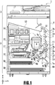
- Fig. 1 is an internal configuration diagram of an inkjet printing apparatus 1 (hereinafter "printing apparatus 1") used in the present embodiment.
- an x-direction is a horizontal direction
- a y-direction (a direction perpendicular to paper) is a direction in which ejection openings are arrayed in a head unit 80, described later
- a z-direction is a vertical direction opposite to the direction of gravity.
- the printing apparatus 1 is a multifunction printer comprising a print unit 2 and a scanner unit 3.
- the printing apparatus 1 can use the print unit 2 and the scanner unit 3 separately or in synchronization to perform various processes related to print operation and scan operation.
- the scanner unit 3 comprises an automatic document feeder (ADF) and a flatbed scanner (FBS) and is capable of scanning a document automatically fed by the ADF as well as scanning a document placed on a document plate of the FBS by a user.
- ADF automatic document feeder
- FBS flatbed scanner
- the present embodiment is directed to the multifunction printer comprising both the print unit 2 and the scanner unit 3, but the scanner unit 3 may be omitted.
- Fig. 1 shows the printing apparatus 1 in a standby state in which neither print operation nor scan operation is performed.
- a first cassette 5A and a second cassette 5B for housing print mediums (cut sheets) S are detachably provided at the bottom of a casing 4 in the vertical direction. Relatively small print mediums of up to an A4 size are stacked and housed in the first cassette 5A and relatively large print mediums of up to an A3 size are stacked and hosed in the second cassette 5B.
- a first feeding unit 6A for feeding the housed print mediums one by one is provided near the first cassette 5A.
- a second feeding unit 6B is provided near the second cassette 5B. In print operation, a print medium S is selectively fed from either one of the cassettes.
- Conveying rollers 7, a discharging roller 12, pinch rollers 7a, spurs 7b, a guide 18, an inner guide 19, and a flapper 11 are conveying mechanisms for guiding a print medium S in a predetermined direction.
- the conveying rollers 7 are drive rollers located upstream and downstream of a head unit 8 and driven by a conveying motor (not shown).
- the pinch rollers 7a are follower rollers that are turned while nipping a print medium S together with the conveying rollers 7.
- the discharging roller 12 is a drive roller located downstream of the conveying rollers 7 and driven by the conveying motor (not shown).
- the spurs 7b nip and convey a print medium S together with the conveying rollers 7 and discharging roller 12 located downstream of the head unit 8.
- the guide 18 is provided in a conveying path of a print medium S to guide the print medium S in a predetermined direction.
- the inner guide 19 is a member extending in the y-direction.
- the inner guide 19 has a curved side surface and guides a print medium S along the side surface.
- the flapper 11 is a member for changing a direction in which a print medium S is conveyed in duplex print operation.
- a discharging tray 13 is a tray for stacking and housing print mediums S that were subjected to print operation and discharged by the discharging roller 12.
- the head unit 8 of the present embodiment is configured by disposing a print head 80 at a head holder 20, described later.
- the print head 80 is a full line type color inkjet print head.
- a plurality of ejection openings configured to eject ink based on print data are arrayed in the y-direction in Fig. 1 so as to correspond to the width of a print medium S.
- an ejection opening surface 8a of the head unit 8 (the print head 80) is oriented vertically downward and capped with a cap unit 10, as shown in Fig. 1 .
- the orientation of the head unit 8 is changed by a print controller 202, described later, such that the ejection opening surface 8a faces a platen 9.
- the platen 9 includes a flat plate extending in the y-direction and supports a print medium S being subjected to print operation by the head unit 8 from the back side. The movement of the head unit 8 from the standby position to a printing position will be described later in detail.
- An ink tank unit 14 separately stores ink of four colors to be supplied to the head unit 8.
- An ink supply unit 15 is provided in the midstream of a flow path connecting the ink tank unit 14 to the head unit 8 to adjust the pressure and flow rate of ink in the print head 80 within a suitable range.
- the present embodiment adopts a circulation type ink supply system, where the ink supply unit 15 adjusts the pressure of ink to be supplied to the print head 80 and the flow rate of ink collected from the print head 80 within a suitable range.
- a maintenance unit 16 comprises the cap unit 10 and a wiping unit 17 and activates them at predetermined timings to perform maintenance operation for the print head 80.
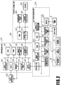
- Fig. 2 is a block diagram showing a control configuration in the printing apparatus 1.
- the control configuration mainly includes a print engine unit 200 that exercises control over the print unit 2, a scanner engine unit 300 that exercises control over the scanner unit 3, and a controller unit 100 that exercises control over the entire printing apparatus 1.
- a print controller 202 controls various mechanisms of the print engine unit 200 under instructions from a main controller 101 of the controller unit 100.
- Various mechanisms of the scanner engine unit 300 are controlled by the main controller 101 of the controller unit 100.
- the control configuration will be described below in detail.
- the main controller 101 including a CPU controls the entire printing apparatus 1 using a RAM 106 as a work area in accordance with various parameters and programs stored in a ROM 107.
- a print job is input from a host apparatus 400 via a host I/F 102 or a wireless I/F 103
- an image processing unit 108 executes predetermined image processing for received image data under instructions from the main controller 101.
- the main controller 101 transmits the image data subjected to the image processing to the print engine unit 200 via a print engine I/F 105.
- the printing apparatus 1 may acquire image data from the host apparatus 400 via a wireless or wired communication or acquire image data from an external storage unit (such as a USB memory) connected to the printing apparatus 1.
- a communication system used for the wireless or wired communication is not limited.
- Wi-Fi Wireless Fidelity; registered trademark
- Bluetooth registered trademark
- a communication system for the wired communication a USB (Universal Serial Bus) and the like can be used.
- the main controller 101 transmits the command to the scanner unit 3 via a scanner engine I/F 109.
- An operating panel 104 is a mechanism to allow a user to do input and output for the printing apparatus 1.
- a user can give an instruction to perform operation such as copying and scanning, set a print mode, and recognize information about the printing apparatus 1 via the operating panel 104.
- the print controller 202 including a CPU controls various mechanisms of the print unit 2 using a RAM 204 as a work area in accordance with various parameters and programs stored in a ROM 203.
- the print controller 202 temporarily stores them in the RAM 204.
- the print controller 202 allows an image processing controller 205 to convert the stored image data into print data such that the head unit 8 can use it for print operation.
- the print controller 202 allows the head unit 8 to perform print operation based on the print data via a head I/F 206.
- the print controller 202 conveys a print medium S by driving the feeding units 6A and 6B, conveying rollers 7, discharging roller 12, and flapper 11 shown in Fig. 1 via a conveyance control unit 207.
- the head unit 8 performs print operation in synchronization with the conveyance operation of the print medium S under instructions from the print controller 202, thereby performing printing.
- a head carriage control unit 208 changes the orientation and position of the head unit 8 in accordance with an operating state of the printing apparatus 1 such as a maintenance state or a printing state.
- the head carriage control unit 208 also controls the connection between the head unit 8 and a joint unit 30 (not shown in Fig. 2 ) for connecting ink to the head unit 8. More specifically, the head carriage control unit 208 includes an elevating motor 37 for elevating the joint unit 30 and a first sensor 21 and a second sensor 22 which are adapted to confirm the vertical position of the joint unit 30. Based on the detection results of these sensors, the elevating motor 37 is driven.
- the connection control between the head unit 8 and the joint unit 30 will be particularly explained later.
- An ink supply control unit 209 controls the ink supply unit 15 such that the pressure of ink supplied to the head unit 8 is within a suitable range.
- a maintenance control unit 210 controls the operation of the cap unit 10 and wiping unit 17 in the maintenance unit 16 when performing maintenance operation for the head unit 8.
- the main controller 101 controls hardware resources of a scanner controller 302 using the RAM 106 as a work area in accordance with various parameters and programs stored in the ROM 107, thereby controlling various mechanisms of the scanner unit 3.
- the main controller 101 controls hardware resources in the scanner controller 302 via a controller I/F 301 to cause a conveyance control unit 304 to convey a document placed on the ADF by a user and cause a sensor 305 to scan the document.
- the scanner controller 302 stores scanned image data in a RAM 303.
- the print controller 202 can convert the image data acquired, as described above, into print data to enable the head unit 8 to perform print operation based on the image data scanned by the scanner controller 302.
- Fig. 3 shows the printing apparatus 1 in a printing state.
- the cap unit 10 is separated from the ejection opening surface 8a of the head unit 8 and the ejection opening surface 8a faces the platen 9.
- the plane of the platen 9 is inclined about 45° with respect to the horizontal plane.
- the ejection opening surface 8a of the head unit 8 in a printing position is also inclined about 45° with respect to the horizontal plane so as to keep a constant distance from the platen 9.
- the print controller 202 uses the maintenance control unit 210 to move the cap unit 10 down to an evacuation position shown in Fig. 3 , thereby separating a cap member from the ejection opening surface 8a of the head unit 8.
- the print controller 202 uses the head carriage control unit 208 to turn the head unit 8 45° while adjusting the vertical height of the head unit 8 such that the ejection opening surface 8a faces the platen 9.
- the print controller 202 reverses the above procedure to move the head unit 8 from the printing position to the standby position.
- the print controller 202 first uses the maintenance control unit 210 and the head carriage control unit 208 to move the head unit 8 to the printing position shown in Fig. 3 .
- the print controller 202 then uses the conveyance control unit 207 to drive either the first feeding unit 6A or the second feeding unit 6B in accordance with the print command and feed a print medium S.
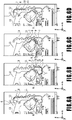
- Figs. 4A to 4C are diagrams showing a conveying path in the case of feeding an A4 size print medium S from the first cassette 5A.
- a print medium S at the top of a stack of print mediums in the first cassette 5A is separated from the rest of the stack by the first feeding unit 6A and conveyed toward a print area P between the platen 9 and the head unit 8 while being nipped between the conveying rollers 7 and the pinch rollers 7a.
- Fig. 4A shows a conveying state where the front end of the print medium S is about to reach the print area P.
- the direction of movement of the print medium S is changed from the horizontal direction (x-direction) to a direction inclined about 45° with respect to the horizontal direction while being fed by the first feeding unit 6A to reach the print area P.
- a plurality of ejection openings provided in the print head 80 eject ink toward the print medium S.
- the back side of the print medium S is supported by the platen 9 so as to keep a constant distance between the ejection opening surface 8a and the print medium S.
- the conveying rollers 7 and the spurs 7b guide the print medium S such that the print medium S passes on the left of the flapper 11 with its tip inclined to the right and is conveyed along the guide 18 in the vertically upward direction of the printing apparatus 1.
- FIG 4B shows a state where the front end of the print medium S has passed through the print area P and the print medium S is being conveyed vertically upward.
- the conveying rollers 7 and the spurs 7b change the direction of movement of the print medium S from the direction inclined about 45° with respect to the horizontal direction in the print area P to the vertically upward direction.
- Fig. 4C shows a state where the front end of the print medium S has passed through the discharging roller 12 and the print medium S is being discharged into the discharging tray 13.
- the discharged print medium S is held in the discharging tray 13 with the side on which an image was printed by the head unit 8 down.
- Figs. 5A to 5C are diagrams showing a conveying path in the case of feeding an A3 size print medium S from the second cassette 5B.
- a print medium S at the top of a stack of print medium in the second cassette 5B is separated from the rest of the stack by the second feeding unit 6B and conveyed toward the print area P between the platen 9 and the head unit 8 while being nipped between the conveying rollers 7 and the pinch rollers 7a.
- Fig. 5A shows a conveying state where the front end of the print medium S is about to reach the print area P.
- the plurality of conveying rollers 7, the plurality of pinch rollers 7a, and the inner guide 19 are provided such that the print medium S is conveyed to the platen 9 while being bent into an S-shape.
- Fig. 5B shows a state where the front end of the print medium S has passed through the print area P and the print medium S is being conveyed vertically upward.
- Fig. 5C shows a state where the front end of the print medium S has passed through the discharging roller 12 and the print medium S is being discharged into the discharging tray 13.
- Figs. 6A to 6D show a conveying path in the case of performing print operation (duplex printing) for the back side (second side) of an A4 size print medium S.
- duplex printing print operation is first performed for the first side (front side) and then performed for the second side (back side).
- a conveying procedure during print operation for the first side is the same as that shown in Figs. 4A to 4C and therefore description will be omitted.
- a conveying procedure subsequent to Fig. 4C will be described below.
- the print controller 202 turns the conveying rollers 7 backward to convey the print medium S into the printing apparatus 1.
- the flapper 11 is controlled by an actuator (not shown) such that the tip of the flapper 11 is inclined to the left, the front end of the print medium S (corresponding to the back end during the print operation for the first side) passes on the right of the flapper 11 and is conveyed vertically downward.
- Fig. 6A shows a state where the front end of the print medium S (corresponding to the back end during the print operation for the first side) is passing on the right of the flapper 11.
- Fig. 6B shows a conveying state where the front end of the print medium S is about to reach the print area P for print operation for the second side.
- Fig. 6C shows a state where the front end of the print medium S has passed through the print area P and the print medium S is being conveyed vertically upward. At this time, the flapper 11 is controlled by the actuator (not shown) such that the tip of the flapper 11 is inclined to the right.
- Fig. 6D shows a state where the front end of the print medium S has passed through the discharging roller 12 and the print medium S is being discharged into the discharging tray 13.
- the maintenance unit 16 of the present embodiment comprises the cap unit 10 and a wiping unit 17 and activates them at predetermined timings to perform maintenance operation.
- Fig. 7 is a diagram showing the printing apparatus 1 in a maintenance state.
- the print controller 202 moves the head unit 8 vertically upward and moves the cap unit 10 vertically downward.
- the print controller 202 then moves the wiping unit 17 from the evacuation position to the right in Fig. 7 .
- the print controller 202 moves the head unit 8 vertically downward to the maintenance position where maintenance operation can be performed.
- the print controller 202 moves the head unit 8 vertically upward while turning it 45°.
- the print controller 202 then moves the wiping unit 17 from the evacuation position to the right.
- the print controller 202 moves the head unit 8 vertically downward to the maintenance position where maintenance operation can be performed by the maintenance unit 16.
- Fig. 8 is a view showing the head holder 20 provided in the printing apparatus 1, for mounting the print head 80 thereon.
- the head holder 20 is a hollow casing extending in the y direction.
- the print head 80 is inserted sideways into the head holder 20 in the +y direction, to be thus mounted in an apparatus body.
- On the back side of the head holder 20 are disposed a connected portion, not shown in Fig. 8 , for making electric connection to the print head 80 to be inserted and a joint unit 30 for making fluid connection to the print head 80.
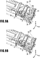
- Figs. 9A and 9B are views showing the print head 80 which is to be inserted into the head holder 20.
- a new print head 80 is mounted on the printing apparatus 1
- a user inserts the print head 80 into an empty head holder 20 in the +y direction.
- An electric connected portion 84 on the head side is disposed at the tip in an insertion direction of the print head 80, and furthermore, an electric connected portion 23 on the holder side is disposed inside of the head holder 20 and at a position opposite to the electric connected portion 84 on the head side.
- the joint unit 30 for connecting the print head 80 and the ink supplying unit 15 to each other retards, in the +z direction, from a region in which the print head 80 slides. Therefore, the joint unit 30 never prevents the print head 80 from sliding.
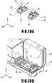
- Figs. 10A and 10B are views showing the connection between the print head 80 and the joint unit 30.
- Fig. 10A shows the joint unit 30 whereas
- Fig. 10B shows a connection region of the print head 80 to be connected to the joint unit 30.
- the connection region of the print head 80 is located at the reverse of a surface at which an ejection opening surface 8a is formed and on the far side in the insertion direction (in the +y direction) in the print head 80.
- the joint unit 30 includes a supply joint portion 32 for supplying ink to the print head 80 and a collection joint portion 33 for collecting ink from the print head 80.
- the joint unit 30 is fixed to a holder plate 31 (see Fig. 11 ) serving as a supporter. At substantially the center of the holder plate 31 is formed a hole 31a, through which a shaft for use in connecting to the print head 80 is inserted.
- the print head 80 includes head joints for supplying and receiving ink (hereinafter referred to as needles 82) and positioning pins 83, as shown in Fig. 10B .
- needles 82 head joints for supplying and receiving ink
- positioning pins 83 positioning pins 83, as shown in Fig. 10B .
- Both of the needles 82 to be connected to the supply joint portion 32 and the needles 82 to be connected to the collection joint portion 33 are provided for four colors, that is, cyan, magenta, yellow, and black.
- the two positioning pins 83 are provided for each of the supply joint portion 32 and the collection joint portion 33.
- a needle joint 34 is arranged at a position corresponding to the needle 82, and furthermore, a pin guide 35 is arranged at a position corresponding to the positioning pin 83.
- the eight needles 82 are connected to the eight needle joints 34, respectively, under the guidance of the insertion of the positioning pins 83 into the pin guides 35, thus achieving the connection between the printing apparatus 1 (the ink supplying unit 15) and the print head 80.
- the connection direction i.e., the z direction
- Fig. 10A shows a state in which a tube 39 is connected to each of the supply joint portion 32 and the collection joint portion 33, the tube 39 is omitted in the other figures for the sake of convenience.
- Fig. 11 is a cross-sectional view showing a state in which the print head 80 and the joint unit 30 are connected to each other in the head holder 20.
- the holder plate 31 rotatably supports a screw shaft 36 which penetrates the hole 31a formed at substantially the center thereof.
- the screw shaft 36 includes a first screw portion 36a formed at the upper part thereof and a second screw portion 36b formed at the lower part thereof.
- the first screw portion 36a can be engaged with a nut hole 40a formed at a lift plate 40 whereas the second screw portion 36b can be engaged with a head nut 81 serving as an engaging portion on the side of the print head 80.
- Fig. 11 shows a state in which the first screw portion 36a is not engaged with the nut hole 40a whereas the second screw portion 36b is engaged with the head nut 81.
- an elevating motor 37 serving as a drive source and a gear train 38 for transmitting the drive force of the elevating motor 37 to the screw shaft 36 are mounted in addition to the above-described supply joint portion 32 and collection joint portion 33.
- the elevating motor 37 is controlled by the head carriage control unit 208 according to the instructions of the print controller 202 illustrated in Fig. 2 .
- the head carriage control unit 208 switches the rotational direction of the elevating motor 37, thus enabling the entire joint unit 30 to ascend and descend in the axial direction of the screw shaft 36 so as to control the connection and separation between the print head 80 and the joint unit 30.
- Figs. 12A and 12B are views showing the ascent and descent of the joint unit 30 in the head holder 20, wherein Fig. 12A shows a state in which the joint unit 30 is separated from the print head 80 and Fig. 12B shows a state in which the joint unit 30 is connected to the print head 80.
- the screw shaft 36 In the separated state shown in Fig. 12A , the screw shaft 36 is held above, and its upper end projects from the lift plate 40.
- the first screw portion 36a is engaged with the nut hole 40a formed at the lift plate 40.
- the second screw portion 36b is separated from the head nut 81.
- the respective needle joints 34 of the supply joint portion 32 and the collection joint portion 33 are separated from the needles 82 of the print head 80, so that the print head 80 is not connected to the printing apparatus 1.
- a user attaches or detaches the print head 80 to or from the head holder 20 in the separated state.
- the elevating motor 37 automatically switches the above-described separated state and connected state. Consequently, the connection and separation between the print head 80 and the printing apparatus 1 can be smoothly achieved without giving any trouble to a user, unlike in the conventional.
- the print controller 202 In transiting from the separated state to the connected state, the print controller 202 confirms the energization between the electric connected portion 84 on the head side and the electric connected portion 23 on the holder side, and then, performs the transition.
- the print controller 202 may erroneously detect that the print head 80 is mounted, although no print head 80 is mounted. In this state, if the joint unit 30 descends, the screw shaft 36 falls on the bottom of the head holder 20 at a timing at which the first screw portion 36a is withdrawn from the nut hole 40a, thereby incurring the risk of breakage of the head holder.
- ink may be supplied under pressure in order to stably supply the ink to a print head having ejection openings arrayed in a high density.
- the printing apparatus 1 in the present embodiment also adopts a mode in which a pump, not shown, supplies the ink under pressure from a sub-tank disposed in the ink supplying unit 15 to the print head 80. This induces a greater concern of leakage or contamination of the ink than in a supply mode utilizing an ink head difference.
- a sensor is additionally prepared for detecting positions above and below the joint unit 30, so as to controllably prevent the ascent and descent of the joint unit 30 more than necessary.
- Figs. 13A to 13D are views stepwise explanatory of the relationship between the position of the joint unit 30 and the detection position of the sensor inside of the head holder 20.
- a lift flag 31b having a predetermined width in a vertical direction is fixed to the side surface of the holder plate 31 in such a manner as to project outside of the holder plate 31.
- the lift flag 31b can be moved in the vertical direction together with the holder plate 31 according to the rotation of the screw shaft 36.
- a first sensor 21 and a second sensor 22 are arranged with a predetermined interval in the vertical direction inside of the head holder 20 and on the way of a path on which the lift flag 31b passes.
- Each of the first sensor 21 and the second sensor 22 is an optical sensor including a light emitter and a light receiver.
- a light beam emitted from the light emitter is received by the light receiver.
- the lift flag 31b is located at a position corresponding to the sensor, a light beam emitted from the light emitter is shut out by the lift flag 31b, and therefore, is not received by the light receiver.
- the head carriage control unit 208 determines the vertical positions of the joint unit 30 based on the combination of whether or not the first sensor receives a light beam (Open/Close) and whether or not the second sensor receives a light beam (Open/Close).
- a lift plate cover 41 for covering the lift plate 40 is placed on the farther upper surface of the lift plate 40, and is screwed to the head holder 20.
- the lift plate 40 and the lift plate cover 41 are not fixed to each other.
- the lift plate 40 can be slightly moved in both of the xy directions and the z direction with respect to the head holder 20.
- a slight gap G is defined between the lift plate 40 and the lift plate cover 41 in a normal state (see Fig. 14A ).
- Fig. 13A shows a separated state similar to that shown in Fig. 12A .
- the lower end of the screw shaft 36 is located above and apart from the head nut 81, and furthermore, the needle joints 34 and the pin guides 35 are separated from the needles 82 and the positioning pins 83 at the print head 80, respectively.
- the lift flag 31b is located above the first sensor 21.
- the detection results of both of the first sensor 21 and the second sensor 22 are Open (not-shut-out).
- the head carriage control unit 208 drives the elevating motor 37 forward, the screw shaft 36 descends while its first screw portion 36a is engaged with the nut hole 40a, and accordingly, the entire joint unit 30 gradually descends. With continuation of this descent for a while, the second screw portion 36b of the screw shaft 36 intrudes into the head nut 81 soon.
- the screw shaft 36 comes to be engaged with both of the lift plate 40 and the print head 80.
- the second screw portion 36b is engaged with the head nut 81 while positioning within an xy plane and receives upward drag from the head nut 81 until the phase of the screw connection of the first screw portion 36a to the nut hole 40a matches the phase of the screw connection of the second screw portion 36b to the head nut 81. Since the screw shaft 36 receives this upward drag, force acts to lift the lift plate 40.
- Figs. 14A and 14B are enlarged views explanatory of the above-described state in detail.
- the gap G shown in Fig. 14A is defined between the lift plate 40 and the lift plate cover 41.
- the lift plate 40 is lifted, thereby narrowing the gap G.
- the lift plate 40 may be brought into contact with the lift plate cover 41, as shown in Fig. 14B . In this manner, defining the gap G between the lift plate 40 and the lift plate cover 41 can suppress any accidental application of the drag applied from the head nut 81 to other members.
- the first screw portion 36a and the second screw portion 36b are disposed at the screw shaft 36 in the positional relationship of separation of a predetermined distance so as to enable the screw shaft 36 to be engaged with both of the lift plate 40 and the print head 80.
- the size of the gap G is previously determined in such a manner as to correspond to a region (i.e., a length) in which the screw shaft 36 can be engaged with both of the lift plate 40 and the print head 80.
- the screw shaft 36 receives the drag from the head nut 81. More specifically, the screw shaft 36 receives the drag from the head nut 81 so as to lift the lift plate 40 until the phase of the screw connection between the first screw portion 36a and the nut hole 40a matches the phase of the screw connection between the second screw portion 36b and the head nut 81. At any rate, previously defining the gap G having a proper size between the lift plate 40 and the lift plate cover 41 enables the joint unit 30 to smoothly ascend and descend.
- the lift plate 40 has a region in which it can move also in the xy directions with respect to the head holder 20. As a consequence, the entire joint unit 30 can move according to positioning the screw shaft 36 that ascends and descends.
- Fig. 13B shows a state in which the joint unit 30 further descends so that the lower end of the lift flag 31b shuts out the first sensor 21.
- the detection value of the first sensor 21 indicates Close (shut-out) whereas the detection value of the second sensor 22 indicates Open (not-shut-out).
- the second screw portion 36b of the screw shaft 36 is engaged with the head nut 81, and furthermore, the first screw portion 36a is engaged with the nut hole 40a of the lift plate 40.
- Fig. 13C shows a state in which the joint unit 30 further descends so that both of the first sensor 21 and the second sensor 22 are shut out by the lift flag 31b.
- the positioning pins 83 of the print head 80 gradually intrude into the pin guides 35 of the joint unit 30, and furthermore, the needles 82 of the print head 80 gradually intrude into the needle joints 34 of the joint unit 30.
- the positioning pins 83 are completely connected to the pin guides 35, and furthermore, the needles 82 are completely connected to the needle joints 34.
- both of the detection values of the first sensor 21 and the second sensor 22 indicate Close (shut-out).
- the print controller 202 can determine based on the detection values of these sensors that the print head 80 is connected to the printing apparatus 1.
- Fig. 13D shows a state in which the joint unit 30 descends and runs over when the print head 80 is not held in the head holder 20. Since the upper end of the lift flag 31b passes the first sensor 21, the detection value of the first sensor 21 results in Open (non-shut-out). In other words, the print controller 202 can presume based on the detection results of these sensors that the print head 80 is not normally held in the head holder 20.
- Fig. 15 is a table illustrating the relative positions of the joint unit 30 to the print head 80, the respective engaged states of the screw shaft 36 corresponding to the positions and the respective detection results of the sensors corresponding to the positions.
- the print controller 202 can determine the position of the joint unit 30 or the connected state between the print head 80 and the joint unit 30 based on the combinations of the detection results of the first sensor 21 and the second sensor 22. Moreover, in the case where the detection value of the first sensor 21 is Open whereas the detection value of the second sensor 22 is Close, the print controller 202 can presume that the print head 80 is not normally disposed.
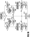
- Fig. 16 is a flowchart illustrating an ascent/descent sequence of the joint unit 30, which is executed by the print controller 202 while using the head carriage control unit 208. This processing is started based on an instruction of a user or the determination of the print controller 202 in the case where the print head 80 and the joint unit 30 need to be connected to or separated from each other, like the replacement of the print head 80.
- the print controller 202 first confirms a value of a joint flag (FLG) in S101.
- the joint flag is adapted to designate the tendency of the connection between the joint unit 30 and the print head 80.
- the print controller 202 proceeds to S102 in order to perform an operation for connecting the joint unit 30 and the print head 80 to each other.
- the print controller 202 proceeds to S108 in order to perform an operation for separating the joint unit 30 and the print head 80 from each other.
- the print controller 202 determines that the joint unit 30 does not need to ascend or descend, performs a predetermined error processing in S114, and ends this processing.
- the print controller 202 In connecting the joint unit 30 and the print head 80 to each other, the print controller 202 confirms the detection result of the second sensor 22 in S102. When the detection result of the second sensor 22 indicates Open, the print controller 202 determines that the joint unit 30 can descend in the current state, and then, it proceeds to S105.
- the print controller 202 ascends the joint unit 30 once in order to reset the state. More specifically, the print controller 202 proceeds to S103, and then, reversely rotates the elevating motor 37 so as to ascend the joint unit 30 by a predetermined amount. Thereafter, when the print controller 202 confirms that the detection result of the second sensor 22 indicates Open in S104, the print controller 202 proceeds to S105 in order to descend the joint unit 30.
- the print controller 202 rotates the elevating motor 37 forward so as to descend the joint unit 30 by a predetermined amount.
- the print controller 202 confirms that both of the detection results of the first sensor 21 and the second sensor 22 indicate Close, it proceeds to S107, and then, sets a connection flag indicating that the print head 80 and the joint unit 30 are connected to each other.
- the print controller 202 performs the predetermined error processing in S114, and then, ends this processing.
- the head carriage control unit 208 confirms the detection result of the first sensor 21 in S108.
- the print controller 202 determines based on the current state that the joint unit 30 can ascend, and then, proceeds to S111.
- the print controller 202 descends the joint unit 30 once in order to reset the state. More specifically, the head carriage control unit 208 rotates the elevating motor 37 forward in S109 so as to descend the joint unit 30 by a predetermined amount. Thereafter, when the print controller 202 confirms that the detection result of the first sensor 21 in S110 indicates Close, the print controller 202 proceeds to S111 in order to ascend the joint unit 30.
- the print controller 202 reversely rotates the elevating motor 37 so as to ascend the joint unit 30 by a predetermined amount.
- the print controller 202 confirms that both of the detection results of the first sensor 21 and the second sensor 22 indicate Open, it sets a separation flag indicating that the print head 80 and the joint unit 30 are separated from each other.
- the print controller 202 performs the predetermined error processing in S114, and then, ends this processing.
- the print controller 202 in the present embodiment controls the rotational direction and rotational amount of the elevating motor 37 while confirming the detection results of the first sensor 21 and the second sensor 22.
- the connection and separation between the print head 80 and the joint unit 30 can be securely achieved without giving any trouble to a user.
- Fig. 17 is a flowchart illustrating a print head mounting confirmation sequence to be executed by the print controller 202 after a user holds the print head 80 in the head holder 20. This processing is started in response to an instruction of a user or the determination of the print controller 202 after the user disposes the print head 80 in the head holder 20 in accordance with the procedures illustrated in Figs. 9A and 9B .
- the print controller 202 confirms the energization between the electric connected portion 23 on the holder side and the electric connected portion 84 on the head side via the head carriage control unit 208 in S11. In the case of the energization, the print controller 202 determines that the print head 80 is electrically connected to the printing apparatus 1, and then, proceeds to S12.
- the print controller 202 Upon completion of the joint unit ascent/descent sequence, the print controller 202 proceeds to S14, in which it is confirmed whether or not the connection flag (S107) is set. In the case where the connection flag is confirmed, the print head 80 and the printing apparatus 1 are regarded as being both electrically and mechanically connected to each other. Thus, the print controller 202 proceeds to S15, and then, allows ink to be circulated in the print head 80. More specifically, the print controller 202 allows ink to be supplied from the ink supplying unit 15 to the print head 80 and the ink to be collected from the print head 80 toward the ink supplying unit 15.
- the print controller 202 proceeds to S16, and then, performs a predetermined error processing, like notifying a user that the print head 80 cannot be successfully mounted. In this manner, the present processing comes to an end.
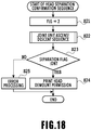
- Fig. 18 is a flowchart illustrating a head separation confirmation sequence to be executed by the print controller 202. This processing is started in response to an instruction of a user or the determination by the print controller 202 in the case where the print head 80 currently being mounted is demounted from the printing apparatus 1.
- the print controller 202 Upon completion of the joint unit ascent/descent sequence, the print controller 202 proceeds to S23, and then, it confirms whether or not the separation flag is set (S113). In the case where the separation flag is confirmed, the print controller 202 performs a predetermined processing for allowing the print head to be demounted in S24, and then, ends this processing.
- the print controller 202 proceeds to S25, and then, performs a predetermined error processing for notifying a user that the print head 80 cannot be successfully disconnected. Thus, the present processing comes to an end.
- connection and separation between the printing apparatus and the print head can be performed securely without placing a burden on a user.
- the present invention is not limited to this. Since a printing apparatus is simply required to be provided with a joint unit for supplying ink from an ink tank to a print head, it is not essential to collect ink from a print head.
- joint unit 30 may be horizontally connected to a print head 80.
- a screw shaft 36 is horizontally moved, and a first sensor and a second sensor are horizontally juxtaposed with each other. Additionally, since no gravity acts in an advance direction of a screw shaft, it is preferable that a spring unit or the like for urging a lift holder toward a print head should be prepared.
- a print head may be of a serial type.
- a print head may be a monochromatic head that uses only black ink or may be a head capable of ejecting various kinds of ink such as light cyan ink and light magenta ink.
- an inkjet printing apparatus capable of having a print head mounted thereon independently of an ink tank requires the connection between the print head and the printing apparatus every time the print head is mounted, and therefore, the present invention can effectively function.
Landscapes
- Engineering & Computer Science (AREA)
- Theoretical Computer Science (AREA)
- Mechanical Engineering (AREA)
- Human Computer Interaction (AREA)
- Physics & Mathematics (AREA)
- General Engineering & Computer Science (AREA)
- General Physics & Mathematics (AREA)
- Ink Jet (AREA)
- Common Mechanisms (AREA)
Abstract
Description
- The present invention relates to an inkjet printing apparatus for ejecting ink so as to print an image.
- There are provided inkjet printing apparatuses, in which a user can replace print heads. Japanese Patent Laid-Open No.
2017-47547 - However, in the configuration disclosed in Japanese Patent Laid-Open No.
2017-47547 - The present invention has been accomplished to solve the above-described problem. Therefore, its object is to provide an inkjet printing apparatus capable of securely connecting a print head to a printing apparatus without placing a burden on a user.
- The present invention in its first aspect provides an inkjet printing apparatus as specified in
claims 1 to 16. - The present invention in its second aspect provides an inkjet printing apparatus as specified in
claim 17. - Further features of the present invention will become apparent from the following description of exemplary embodiments with reference to the attached drawings.
-
-
Fig. 1 is a diagram showing a printing apparatus in a standby state; -
Fig. 2 is a control configuration diagram of the printing apparatus; -
Fig. 3 is a diagram showing the printing apparatus in a printing state; -
Figs. 4A to 4C are conveying path diagrams of a print medium fed from a first cassette; -
Figs. 5A to 5C are conveying path diagrams of a print medium fed from a second cassette; -
Figs. 6A to 6D are conveying path diagrams in the case of performing print operation for the back side of a print medium; -
Fig. 7 is a diagram showing the printing apparatus in a maintenance state; -
Fig. 8 is a view showing a head holder; -
Figs. 9A and 9B are views showing a print head which is to be inserted; -
Figs. 10A and 10B are views showing a connected portion between the print head and a joint unit; -
Fig. 11 is a view showing the print head and the joint unit at the head holder; -
Figs. 12A and 12B are views showing the ascent and descent of the joint unit; -
Figs. 13A to 13D are views showing positions of the joint unit and detection positions of sensors; -
Figs. 14A and 14B are enlarged views showing a lift plate and a lift plate cover; -
Fig. 15 is a table illustrating the states of each member at corresponding positions of the joint unit; -
Fig. 16 is a flowchart illustrating an ascent/descent sequence of the joint unit; -
Fig. 17 is a flowchart illustrating a print head mounting confirmation sequence; and -
Fig. 18 is a flowchart illustrating a head demounting confirmation sequence. -
Fig. 1 is an internal configuration diagram of an inkjet printing apparatus 1 (hereinafter "printing apparatus 1") used in the present embodiment. In the drawings, an x-direction is a horizontal direction, a y-direction (a direction perpendicular to paper) is a direction in which ejection openings are arrayed in ahead unit 80, described later, and a z-direction is a vertical direction opposite to the direction of gravity. - The
printing apparatus 1 is a multifunction printer comprising aprint unit 2 and ascanner unit 3. Theprinting apparatus 1 can use theprint unit 2 and thescanner unit 3 separately or in synchronization to perform various processes related to print operation and scan operation. Thescanner unit 3 comprises an automatic document feeder (ADF) and a flatbed scanner (FBS) and is capable of scanning a document automatically fed by the ADF as well as scanning a document placed on a document plate of the FBS by a user. The present embodiment is directed to the multifunction printer comprising both theprint unit 2 and thescanner unit 3, but thescanner unit 3 may be omitted.Fig. 1 shows theprinting apparatus 1 in a standby state in which neither print operation nor scan operation is performed. - In the
print unit 2, afirst cassette 5A and asecond cassette 5B for housing print mediums (cut sheets) S are detachably provided at the bottom of a casing 4 in the vertical direction. Relatively small print mediums of up to an A4 size are stacked and housed in thefirst cassette 5A and relatively large print mediums of up to an A3 size are stacked and hosed in thesecond cassette 5B. Afirst feeding unit 6A for feeding the housed print mediums one by one is provided near thefirst cassette 5A. Similarly, asecond feeding unit 6B is provided near thesecond cassette 5B. In print operation, a print medium S is selectively fed from either one of the cassettes. - Conveying
rollers 7, adischarging roller 12,pinch rollers 7a,spurs 7b, aguide 18, aninner guide 19, and aflapper 11 are conveying mechanisms for guiding a print medium S in a predetermined direction. Theconveying rollers 7 are drive rollers located upstream and downstream of ahead unit 8 and driven by a conveying motor (not shown). Thepinch rollers 7a are follower rollers that are turned while nipping a print medium S together with theconveying rollers 7. Thedischarging roller 12 is a drive roller located downstream of theconveying rollers 7 and driven by the conveying motor (not shown). Thespurs 7b nip and convey a print medium S together with theconveying rollers 7 anddischarging roller 12 located downstream of thehead unit 8. - The
guide 18 is provided in a conveying path of a print medium S to guide the print medium S in a predetermined direction. Theinner guide 19 is a member extending in the y-direction. Theinner guide 19 has a curved side surface and guides a print medium S along the side surface. Theflapper 11 is a member for changing a direction in which a print medium S is conveyed in duplex print operation. Adischarging tray 13 is a tray for stacking and housing print mediums S that were subjected to print operation and discharged by thedischarging roller 12. - The
head unit 8 of the present embodiment is configured by disposing aprint head 80 at ahead holder 20, described later. Theprint head 80 is a full line type color inkjet print head. In thehead unit 8, a plurality of ejection openings configured to eject ink based on print data are arrayed in the y-direction inFig. 1 so as to correspond to the width of a print medium S. When thehead unit 8 is in a standby position, anejection opening surface 8a of the head unit 8 (the print head 80) is oriented vertically downward and capped with acap unit 10, as shown inFig. 1 . In print operation, the orientation of thehead unit 8 is changed by aprint controller 202, described later, such that theejection opening surface 8a faces aplaten 9. Theplaten 9 includes a flat plate extending in the y-direction and supports a print medium S being subjected to print operation by thehead unit 8 from the back side. The movement of thehead unit 8 from the standby position to a printing position will be described later in detail. - An
ink tank unit 14 separately stores ink of four colors to be supplied to thehead unit 8. Anink supply unit 15 is provided in the midstream of a flow path connecting theink tank unit 14 to thehead unit 8 to adjust the pressure and flow rate of ink in theprint head 80 within a suitable range. The present embodiment adopts a circulation type ink supply system, where theink supply unit 15 adjusts the pressure of ink to be supplied to theprint head 80 and the flow rate of ink collected from theprint head 80 within a suitable range. - A
maintenance unit 16 comprises thecap unit 10 and awiping unit 17 and activates them at predetermined timings to perform maintenance operation for theprint head 80. -
Fig. 2 is a block diagram showing a control configuration in theprinting apparatus 1. The control configuration mainly includes aprint engine unit 200 that exercises control over theprint unit 2, ascanner engine unit 300 that exercises control over thescanner unit 3, and acontroller unit 100 that exercises control over theentire printing apparatus 1. Aprint controller 202 controls various mechanisms of theprint engine unit 200 under instructions from amain controller 101 of thecontroller unit 100. Various mechanisms of thescanner engine unit 300 are controlled by themain controller 101 of thecontroller unit 100. The control configuration will be described below in detail. - In the
controller unit 100, themain controller 101 including a CPU controls theentire printing apparatus 1 using aRAM 106 as a work area in accordance with various parameters and programs stored in aROM 107. For example, when a print job is input from ahost apparatus 400 via a host I/F 102 or a wireless I/F 103, animage processing unit 108 executes predetermined image processing for received image data under instructions from themain controller 101. Themain controller 101 transmits the image data subjected to the image processing to theprint engine unit 200 via a print engine I/F 105. - The
printing apparatus 1 may acquire image data from thehost apparatus 400 via a wireless or wired communication or acquire image data from an external storage unit (such as a USB memory) connected to theprinting apparatus 1. A communication system used for the wireless or wired communication is not limited. For example, as a communication system for the wireless communication, Wi-Fi (Wireless Fidelity; registered trademark) and Bluetooth (registered trademark) can be used. As a communication system for the wired communication, a USB (Universal Serial Bus) and the like can be used. For example, when a scan command is input from thehost apparatus 400, themain controller 101 transmits the command to thescanner unit 3 via a scanner engine I/F 109. - An operating panel 104 is a mechanism to allow a user to do input and output for the
printing apparatus 1. A user can give an instruction to perform operation such as copying and scanning, set a print mode, and recognize information about theprinting apparatus 1 via the operating panel 104. - In the
print engine unit 200, theprint controller 202 including a CPU controls various mechanisms of theprint unit 2 using aRAM 204 as a work area in accordance with various parameters and programs stored in aROM 203. When various commands and image data are received via a controller I/F 201, theprint controller 202 temporarily stores them in theRAM 204. Theprint controller 202 allows animage processing controller 205 to convert the stored image data into print data such that thehead unit 8 can use it for print operation. After the generation of the print data, theprint controller 202 allows thehead unit 8 to perform print operation based on the print data via a head I/F 206. At this time, theprint controller 202 conveys a print medium S by driving thefeeding units rollers 7, dischargingroller 12, andflapper 11 shown inFig. 1 via aconveyance control unit 207. Thehead unit 8 performs print operation in synchronization with the conveyance operation of the print medium S under instructions from theprint controller 202, thereby performing printing. - A head
carriage control unit 208 changes the orientation and position of thehead unit 8 in accordance with an operating state of theprinting apparatus 1 such as a maintenance state or a printing state. The headcarriage control unit 208 also controls the connection between thehead unit 8 and a joint unit 30 (not shown inFig. 2 ) for connecting ink to thehead unit 8. More specifically, the headcarriage control unit 208 includes an elevatingmotor 37 for elevating thejoint unit 30 and afirst sensor 21 and asecond sensor 22 which are adapted to confirm the vertical position of thejoint unit 30. Based on the detection results of these sensors, the elevatingmotor 37 is driven. The connection control between thehead unit 8 and thejoint unit 30 will be particularly explained later. - An ink supply control unit 209 controls the
ink supply unit 15 such that the pressure of ink supplied to thehead unit 8 is within a suitable range. Amaintenance control unit 210 controls the operation of thecap unit 10 and wipingunit 17 in themaintenance unit 16 when performing maintenance operation for thehead unit 8. - In the
scanner engine unit 300, themain controller 101 controls hardware resources of ascanner controller 302 using theRAM 106 as a work area in accordance with various parameters and programs stored in theROM 107, thereby controlling various mechanisms of thescanner unit 3. For example, themain controller 101 controls hardware resources in thescanner controller 302 via a controller I/F 301 to cause aconveyance control unit 304 to convey a document placed on the ADF by a user and cause asensor 305 to scan the document. Thescanner controller 302 stores scanned image data in aRAM 303. Theprint controller 202 can convert the image data acquired, as described above, into print data to enable thehead unit 8 to perform print operation based on the image data scanned by thescanner controller 302. -
Fig. 3 shows theprinting apparatus 1 in a printing state. As compared with the standby state shown inFig. 1 , thecap unit 10 is separated from theejection opening surface 8a of thehead unit 8 and theejection opening surface 8a faces theplaten 9. In the present embodiment, the plane of theplaten 9 is inclined about 45° with respect to the horizontal plane. Theejection opening surface 8a of thehead unit 8 in a printing position is also inclined about 45° with respect to the horizontal plane so as to keep a constant distance from theplaten 9. - In the case of moving the
head unit 8 from the standby position shown inFig. 1 to the printing position shown inFig. 3 , theprint controller 202 uses themaintenance control unit 210 to move thecap unit 10 down to an evacuation position shown inFig. 3 , thereby separating a cap member from theejection opening surface 8a of thehead unit 8. Theprint controller 202 then uses the headcarriage control unit 208 to turn thehead unit 8 45° while adjusting the vertical height of thehead unit 8 such that theejection opening surface 8a faces theplaten 9. After the completion of print operation, theprint controller 202 reverses the above procedure to move thehead unit 8 from the printing position to the standby position. - Next, a conveying path of a print medium S in the
print unit 2 will be described. When a print command is input, theprint controller 202 first uses themaintenance control unit 210 and the headcarriage control unit 208 to move thehead unit 8 to the printing position shown inFig. 3 . Theprint controller 202 then uses theconveyance control unit 207 to drive either thefirst feeding unit 6A or thesecond feeding unit 6B in accordance with the print command and feed a print medium S. -
Figs. 4A to 4C are diagrams showing a conveying path in the case of feeding an A4 size print medium S from thefirst cassette 5A. A print medium S at the top of a stack of print mediums in thefirst cassette 5A is separated from the rest of the stack by thefirst feeding unit 6A and conveyed toward a print area P between theplaten 9 and thehead unit 8 while being nipped between the conveyingrollers 7 and thepinch rollers 7a.Fig. 4A shows a conveying state where the front end of the print medium S is about to reach the print area P. The direction of movement of the print medium S is changed from the horizontal direction (x-direction) to a direction inclined about 45° with respect to the horizontal direction while being fed by thefirst feeding unit 6A to reach the print area P. - In the print area P, a plurality of ejection openings provided in the
print head 80 eject ink toward the print medium S. In an area where ink is applied to the print medium S, the back side of the print medium S is supported by theplaten 9 so as to keep a constant distance between theejection opening surface 8a and the print medium S. After ink is applied to the print medium S, the conveyingrollers 7 and thespurs 7b guide the print medium S such that the print medium S passes on the left of theflapper 11 with its tip inclined to the right and is conveyed along theguide 18 in the vertically upward direction of theprinting apparatus 1.Fig. 4B shows a state where the front end of the print medium S has passed through the print area P and the print medium S is being conveyed vertically upward. The conveyingrollers 7 and thespurs 7b change the direction of movement of the print medium S from the direction inclined about 45° with respect to the horizontal direction in the print area P to the vertically upward direction. - After being conveyed vertically upward, the print medium S is discharged into the discharging
tray 13 by the dischargingroller 12 and thespurs 7b.Fig. 4C shows a state where the front end of the print medium S has passed through the dischargingroller 12 and the print medium S is being discharged into the dischargingtray 13. The discharged print medium S is held in the dischargingtray 13 with the side on which an image was printed by thehead unit 8 down. -
Figs. 5A to 5C are diagrams showing a conveying path in the case of feeding an A3 size print medium S from thesecond cassette 5B. A print medium S at the top of a stack of print medium in thesecond cassette 5B is separated from the rest of the stack by thesecond feeding unit 6B and conveyed toward the print area P between theplaten 9 and thehead unit 8 while being nipped between the conveyingrollers 7 and thepinch rollers 7a. -
Fig. 5A shows a conveying state where the front end of the print medium S is about to reach the print area P. In a part of the conveying path, through which the print medium S is fed by thesecond feeding unit 6B toward the print area P, the plurality of conveyingrollers 7, the plurality ofpinch rollers 7a, and theinner guide 19 are provided such that the print medium S is conveyed to theplaten 9 while being bent into an S-shape. - The rest of the conveying path is the same as that in the case of the A4 size print medium S shown in
Figs. 4B and 4C .Fig. 5B shows a state where the front end of the print medium S has passed through the print area P and the print medium S is being conveyed vertically upward.Fig. 5C shows a state where the front end of the print medium S has passed through the dischargingroller 12 and the print medium S is being discharged into the dischargingtray 13. -
Figs. 6A to 6D show a conveying path in the case of performing print operation (duplex printing) for the back side (second side) of an A4 size print medium S. In the case of duplex printing, print operation is first performed for the first side (front side) and then performed for the second side (back side). A conveying procedure during print operation for the first side is the same as that shown inFigs. 4A to 4C and therefore description will be omitted. A conveying procedure subsequent toFig. 4C will be described below. - After the
head unit 8 finishes print operation for the first side and the back end of the print medium S passes by theflapper 11, theprint controller 202 turns the conveyingrollers 7 backward to convey the print medium S into theprinting apparatus 1. At this time, since theflapper 11 is controlled by an actuator (not shown) such that the tip of theflapper 11 is inclined to the left, the front end of the print medium S (corresponding to the back end during the print operation for the first side) passes on the right of theflapper 11 and is conveyed vertically downward.Fig. 6A shows a state where the front end of the print medium S (corresponding to the back end during the print operation for the first side) is passing on the right of theflapper 11. - Then, the print medium S is conveyed along the curved outer surface of the
inner guide 19 and then conveyed again to the print area P between thehead unit 8 and theplaten 9. At this time, the second side of the print medium S faces theejection opening surface 8a of thehead unit 8.Fig. 6B shows a conveying state where the front end of the print medium S is about to reach the print area P for print operation for the second side. - The rest of the conveying path is the same as that in the case of the print operation for the first side shown in
Figs. 4B and 4C .Fig. 6C shows a state where the front end of the print medium S has passed through the print area P and the print medium S is being conveyed vertically upward. At this time, theflapper 11 is controlled by the actuator (not shown) such that the tip of theflapper 11 is inclined to the right.Fig. 6D shows a state where the front end of the print medium S has passed through the dischargingroller 12 and the print medium S is being discharged into the dischargingtray 13. - Next, maintenance operation for the
head unit 8 will be described. As described with reference toFig. 1 , themaintenance unit 16 of the present embodiment comprises thecap unit 10 and awiping unit 17 and activates them at predetermined timings to perform maintenance operation. -
Fig. 7 is a diagram showing theprinting apparatus 1 in a maintenance state. In the case of moving thehead unit 8 from the standby position shown inFig. 1 to a maintenance position shown inFig. 7 , theprint controller 202 moves thehead unit 8 vertically upward and moves thecap unit 10 vertically downward. Theprint controller 202 then moves the wipingunit 17 from the evacuation position to the right inFig. 7 . After that, theprint controller 202 moves thehead unit 8 vertically downward to the maintenance position where maintenance operation can be performed. - On the other hand, in the case of moving the
head unit 8 from the printing position shown inFig. 3 to the maintenance position shown inFig. 7 , theprint controller 202 moves thehead unit 8 vertically upward while turning it 45°. Theprint controller 202 then moves the wipingunit 17 from the evacuation position to the right. Following that, theprint controller 202 moves thehead unit 8 vertically downward to the maintenance position where maintenance operation can be performed by themaintenance unit 16. - Next, a description will be given of a configuration for mounting the
print head 80 on theprinting apparatus 1. When theprint head 80 is mounted on or demounted from theprinting apparatus 1, thehead unit 8 is moved to a position higher by about several centimeters than the maintenance position shown inFig. 7 . -
Fig. 8 is a view showing thehead holder 20 provided in theprinting apparatus 1, for mounting theprint head 80 thereon. Thehead holder 20 is a hollow casing extending in the y direction. Theprint head 80 is inserted sideways into thehead holder 20 in the +y direction, to be thus mounted in an apparatus body. On the back side of thehead holder 20 are disposed a connected portion, not shown inFig. 8 , for making electric connection to theprint head 80 to be inserted and ajoint unit 30 for making fluid connection to theprint head 80. -
Figs. 9A and 9B are views showing theprint head 80 which is to be inserted into thehead holder 20. When anew print head 80 is mounted on theprinting apparatus 1, a user inserts theprint head 80 into anempty head holder 20 in the +y direction. An electric connectedportion 84 on the head side is disposed at the tip in an insertion direction of theprint head 80, and furthermore, an electric connectedportion 23 on the holder side is disposed inside of thehead holder 20 and at a position opposite to the electric connectedportion 84 on the head side. As a consequence, when the user inserts theprint head 80 into thehead holder 20, and then, slides it in the y direction, these electric connected portions are joined to each other, so that theprint head 80 is electrically connected to theprinting apparatus 1. Meanwhile, thejoint unit 30 for connecting theprint head 80 and theink supplying unit 15 to each other retards, in the +z direction, from a region in which theprint head 80 slides. Therefore, thejoint unit 30 never prevents theprint head 80 from sliding. -
Figs. 10A and 10B are views showing the connection between theprint head 80 and thejoint unit 30.Fig. 10A shows thejoint unit 30 whereasFig. 10B shows a connection region of theprint head 80 to be connected to thejoint unit 30. The connection region of theprint head 80 is located at the reverse of a surface at which anejection opening surface 8a is formed and on the far side in the insertion direction (in the +y direction) in theprint head 80. - The
joint unit 30 includes a supplyjoint portion 32 for supplying ink to theprint head 80 and a collectionjoint portion 33 for collecting ink from theprint head 80. Thejoint unit 30 is fixed to a holder plate 31 (seeFig. 11 ) serving as a supporter. At substantially the center of theholder plate 31 is formed ahole 31a, through which a shaft for use in connecting to theprint head 80 is inserted. - In the meantime, the
print head 80 includes head joints for supplying and receiving ink (hereinafter referred to as needles 82) and positioning pins 83, as shown inFig. 10B . Both of theneedles 82 to be connected to the supplyjoint portion 32 and theneedles 82 to be connected to the collectionjoint portion 33 are provided for four colors, that is, cyan, magenta, yellow, and black. Moreover, the twopositioning pins 83 are provided for each of the supplyjoint portion 32 and the collectionjoint portion 33. - At a connection surface of the
joint unit 30, connected to theprint head 80, a needle joint 34 is arranged at a position corresponding to theneedle 82, and furthermore, apin guide 35 is arranged at a position corresponding to thepositioning pin 83. The eightneedles 82 are connected to the eightneedle joints 34, respectively, under the guidance of the insertion of the positioning pins 83 into the pin guides 35, thus achieving the connection between the printing apparatus 1 (the ink supplying unit 15) and theprint head 80. In this manner, the connection direction (i.e., the z direction) between theprint head 80 and thejoint unit 30 is designed to cross a direction in which theprint head 80 is mounted on the printing apparatus 1 (i.e., the y direction). Here, althoughFig. 10A shows a state in which atube 39 is connected to each of the supplyjoint portion 32 and the collectionjoint portion 33, thetube 39 is omitted in the other figures for the sake of convenience. -
Fig. 11 is a cross-sectional view showing a state in which theprint head 80 and thejoint unit 30 are connected to each other in thehead holder 20. Theholder plate 31 rotatably supports ascrew shaft 36 which penetrates thehole 31a formed at substantially the center thereof. Thescrew shaft 36 includes afirst screw portion 36a formed at the upper part thereof and asecond screw portion 36b formed at the lower part thereof. Thefirst screw portion 36a can be engaged with anut hole 40a formed at alift plate 40 whereas thesecond screw portion 36b can be engaged with ahead nut 81 serving as an engaging portion on the side of theprint head 80.Fig. 11 shows a state in which thefirst screw portion 36a is not engaged with thenut hole 40a whereas thesecond screw portion 36b is engaged with thehead nut 81. - On the
holder plate 31, an elevatingmotor 37 serving as a drive source and agear train 38 for transmitting the drive force of the elevatingmotor 37 to thescrew shaft 36 are mounted in addition to the above-described supplyjoint portion 32 and collectionjoint portion 33. The elevatingmotor 37 is controlled by the headcarriage control unit 208 according to the instructions of theprint controller 202 illustrated inFig. 2 . In other words, the headcarriage control unit 208 switches the rotational direction of the elevatingmotor 37, thus enabling the entirejoint unit 30 to ascend and descend in the axial direction of thescrew shaft 36 so as to control the connection and separation between theprint head 80 and thejoint unit 30. -
Figs. 12A and 12B are views showing the ascent and descent of thejoint unit 30 in thehead holder 20, whereinFig. 12A shows a state in which thejoint unit 30 is separated from theprint head 80 andFig. 12B shows a state in which thejoint unit 30 is connected to theprint head 80. - In the separated state shown in
Fig. 12A , thescrew shaft 36 is held above, and its upper end projects from thelift plate 40. Thefirst screw portion 36a is engaged with thenut hole 40a formed at thelift plate 40. Thesecond screw portion 36b is separated from thehead nut 81. As a consequence, therespective needle joints 34 of the supplyjoint portion 32 and the collectionjoint portion 33 are separated from theneedles 82 of theprint head 80, so that theprint head 80 is not connected to theprinting apparatus 1. In the present embodiment, a user attaches or detaches theprint head 80 to or from thehead holder 20 in the separated state. - In the connected state shown in
Fig. 12B , thescrew shaft 36 is held below, and thefirst screw portion 36a is withdrawn downward of thelift plate 40. In other words, thefirst screw portion 36a is not engaged with thenut hole 40a formed at thelift plate 40 whereas only thesecond screw portion 36b intrudes and is engaged with thehead nut 81. At this time, the needle joints 34 are joined with theneedles 82 of theprint head 80, thus connecting theprint head 80 to theprinting apparatus 1. - In the present embodiment, the elevating
motor 37 automatically switches the above-described separated state and connected state. Consequently, the connection and separation between theprint head 80 and theprinting apparatus 1 can be smoothly achieved without giving any trouble to a user, unlike in the conventional. - In transiting from the separated state to the connected state, the
print controller 202 confirms the energization between the electric connectedportion 84 on the head side and the electric connectedportion 23 on the holder side, and then, performs the transition. Here, if an electric contact is adversely influenced by static electricity or the like, theprint controller 202 may erroneously detect that theprint head 80 is mounted, although noprint head 80 is mounted. In this state, if thejoint unit 30 descends, thescrew shaft 36 falls on the bottom of thehead holder 20 at a timing at which thefirst screw portion 36a is withdrawn from thenut hole 40a, thereby incurring the risk of breakage of the head holder. - Alternatively, if ink is started to be supplied from the supply
joint portion 32 in the state of the erroneous detection that theprint head 80 is mounted, the supplied ink contaminates the inside of the apparatus. In particular, in an inkjet printing apparatus of a full line type, ink may be supplied under pressure in order to stably supply the ink to a print head having ejection openings arrayed in a high density. Theprinting apparatus 1 in the present embodiment also adopts a mode in which a pump, not shown, supplies the ink under pressure from a sub-tank disposed in theink supplying unit 15 to theprint head 80. This induces a greater concern of leakage or contamination of the ink than in a supply mode utilizing an ink head difference. - More specifically, in consideration of an adverse effect by static electricity or the like, it is not favorable from the viewpoint of reliability to securely determine based on only the energization whether or not the
print head 80 is actually mounted. In view of this, in the present embodiment, a sensor is additionally prepared for detecting positions above and below thejoint unit 30, so as to controllably prevent the ascent and descent of thejoint unit 30 more than necessary. -
Figs. 13A to 13D are views stepwise explanatory of the relationship between the position of thejoint unit 30 and the detection position of the sensor inside of thehead holder 20. Alift flag 31b having a predetermined width in a vertical direction is fixed to the side surface of theholder plate 31 in such a manner as to project outside of theholder plate 31. As a consequence, thelift flag 31b can be moved in the vertical direction together with theholder plate 31 according to the rotation of thescrew shaft 36. In the meantime, afirst sensor 21 and asecond sensor 22 are arranged with a predetermined interval in the vertical direction inside of thehead holder 20 and on the way of a path on which thelift flag 31b passes. - Each of the
first sensor 21 and thesecond sensor 22 is an optical sensor including a light emitter and a light receiver. When thelift flag 31b is positioned apart from the sensors, a light beam emitted from the light emitter is received by the light receiver. When thelift flag 31b is located at a position corresponding to the sensor, a light beam emitted from the light emitter is shut out by thelift flag 31b, and therefore, is not received by the light receiver. The headcarriage control unit 208 determines the vertical positions of thejoint unit 30 based on the combination of whether or not the first sensor receives a light beam (Open/Close) and whether or not the second sensor receives a light beam (Open/Close). - A lift plate cover 41 for covering the
lift plate 40 is placed on the farther upper surface of thelift plate 40, and is screwed to thehead holder 20. Here, thelift plate 40 and thelift plate cover 41 are not fixed to each other. Thelift plate 40 can be slightly moved in both of the xy directions and the z direction with respect to thehead holder 20. A slight gap G is defined between thelift plate 40 and the lift plate cover 41 in a normal state (seeFig. 14A ). -
Fig. 13A shows a separated state similar to that shown inFig. 12A . The lower end of thescrew shaft 36 is located above and apart from thehead nut 81, and furthermore, the needle joints 34 and the pin guides 35 are separated from theneedles 82 and the positioning pins 83 at theprint head 80, respectively. Thelift flag 31b is located above thefirst sensor 21. The detection results of both of thefirst sensor 21 and thesecond sensor 22 are Open (not-shut-out). - When the head
carriage control unit 208 drives the elevatingmotor 37 forward, thescrew shaft 36 descends while itsfirst screw portion 36a is engaged with thenut hole 40a, and accordingly, the entirejoint unit 30 gradually descends. With continuation of this descent for a while, thesecond screw portion 36b of thescrew shaft 36 intrudes into thehead nut 81 soon. - When the
second screw portion 36b is engaged with thehead nut 81, thescrew shaft 36 comes to be engaged with both of thelift plate 40 and theprint head 80. Thesecond screw portion 36b is engaged with thehead nut 81 while positioning within an xy plane and receives upward drag from thehead nut 81 until the phase of the screw connection of thefirst screw portion 36a to thenut hole 40a matches the phase of the screw connection of thesecond screw portion 36b to thehead nut 81. Since thescrew shaft 36 receives this upward drag, force acts to lift thelift plate 40. -
Figs. 14A and 14B are enlarged views explanatory of the above-described state in detail. In the normal state, the gap G shown inFig. 14A is defined between thelift plate 40 and thelift plate cover 41. On the other hand, in a case where thescrew shaft 36 receives the drag from thehead nut 81, thelift plate 40 is lifted, thereby narrowing the gap G. Thelift plate 40 may be brought into contact with thelift plate cover 41, as shown inFig. 14B . In this manner, defining the gap G between thelift plate 40 and the lift plate cover 41 can suppress any accidental application of the drag applied from thehead nut 81 to other members. - Thereafter, when the phase of the screw connection between the
second screw portion 36b and thehead nut 81 matches with the phase of the screw connection between thefirst screw portion 36a and thenut hole 40a, thescrew shaft 36 starts to descend again. At this time, since thescrew shaft 36 does not receive any drag from thehead nut 81, thelift plate 40 returns to the position shown inFig. 14A . Moreover, when thescrew shaft 36 further descends, thefirst screw portion 36a is withdrawn downward of thenut hole 40a, thus releasing thefirst screw portion 36a and thenut hole 40a from being engaged with each other. More specifically, thescrew shaft 36 is released from being engaged with thelift plate 40, and thus, is engaged only with theprint head 80. - As described above, the
first screw portion 36a and thesecond screw portion 36b are disposed at thescrew shaft 36 in the positional relationship of separation of a predetermined distance so as to enable thescrew shaft 36 to be engaged with both of thelift plate 40 and theprint head 80. In this way, the state in which thejoint unit 30 is engaged with thehead holder 20 can be smoothly changed to the state in which it is engaged with theprint head 80. Here, the size of the gap G is previously determined in such a manner as to correspond to a region (i.e., a length) in which thescrew shaft 36 can be engaged with both of thelift plate 40 and theprint head 80. - Incidentally, also when the
joint unit 30 is separated from theprint head 80, thescrew shaft 36 receives the drag from thehead nut 81. More specifically, thescrew shaft 36 receives the drag from thehead nut 81 so as to lift thelift plate 40 until the phase of the screw connection between thefirst screw portion 36a and thenut hole 40a matches the phase of the screw connection between thesecond screw portion 36b and thehead nut 81. At any rate, previously defining the gap G having a proper size between thelift plate 40 and thelift plate cover 41 enables thejoint unit 30 to smoothly ascend and descend. - As described already, the
lift plate 40 has a region in which it can move also in the xy directions with respect to thehead holder 20. As a consequence, the entirejoint unit 30 can move according to positioning thescrew shaft 36 that ascends and descends. - Returning to
Figs. 13A to 13D , the description will be continued below.Fig. 13B shows a state in which thejoint unit 30 further descends so that the lower end of thelift flag 31b shuts out thefirst sensor 21. At this time, the detection value of thefirst sensor 21 indicates Close (shut-out) whereas the detection value of thesecond sensor 22 indicates Open (not-shut-out). Thesecond screw portion 36b of thescrew shaft 36 is engaged with thehead nut 81, and furthermore, thefirst screw portion 36a is engaged with thenut hole 40a of thelift plate 40. -
Fig. 13C shows a state in which thejoint unit 30 further descends so that both of thefirst sensor 21 and thesecond sensor 22 are shut out by thelift flag 31b. From the state shown inFig. 13B to the state shown inFig. 13C , the positioning pins 83 of theprint head 80 gradually intrude into the pin guides 35 of thejoint unit 30, and furthermore, theneedles 82 of theprint head 80 gradually intrude into the needle joints 34 of thejoint unit 30. In the state shown inFig. 13C , the positioning pins 83 are completely connected to the pin guides 35, and furthermore, theneedles 82 are completely connected to the needle joints 34. - At this time, both of the detection values of the
first sensor 21 and thesecond sensor 22 indicate Close (shut-out). Theprint controller 202 can determine based on the detection values of these sensors that theprint head 80 is connected to theprinting apparatus 1. -
Fig. 13D shows a state in which thejoint unit 30 descends and runs over when theprint head 80 is not held in thehead holder 20. Since the upper end of thelift flag 31b passes thefirst sensor 21, the detection value of thefirst sensor 21 results in Open (non-shut-out). In other words, theprint controller 202 can presume based on the detection results of these sensors that theprint head 80 is not normally held in thehead holder 20. -
Fig. 15 is a table illustrating the relative positions of thejoint unit 30 to theprint head 80, the respective engaged states of thescrew shaft 36 corresponding to the positions and the respective detection results of the sensors corresponding to the positions. Theprint controller 202 can determine the position of thejoint unit 30 or the connected state between theprint head 80 and thejoint unit 30 based on the combinations of the detection results of thefirst sensor 21 and thesecond sensor 22. Moreover, in the case where the detection value of thefirst sensor 21 is Open whereas the detection value of thesecond sensor 22 is Close, theprint controller 202 can presume that theprint head 80 is not normally disposed. -
Fig. 16 is a flowchart illustrating an ascent/descent sequence of thejoint unit 30, which is executed by theprint controller 202 while using the headcarriage control unit 208. This processing is started based on an instruction of a user or the determination of theprint controller 202 in the case where theprint head 80 and thejoint unit 30 need to be connected to or separated from each other, like the replacement of theprint head 80. - Upon the start of this processing, the
print controller 202 first confirms a value of a joint flag (FLG) in S101. The joint flag is adapted to designate the tendency of the connection between thejoint unit 30 and theprint head 80. FLG = 1 when a connecting operation is performed; and FLG = 2 when a separating operation is performed. FLG = 0 when neither the connecting operation nor the separating operation is performed. For example, FLG = 0 when theprinting apparatus 1 is shipped. - In the case where FLG = 1 in S101, the
print controller 202 proceeds to S102 in order to perform an operation for connecting thejoint unit 30 and theprint head 80 to each other. In the case where FLG = 2, theprint controller 202 proceeds to S108 in order to perform an operation for separating thejoint unit 30 and theprint head 80 from each other. In the case where FLG = 0, theprint controller 202 determines that thejoint unit 30 does not need to ascend or descend, performs a predetermined error processing in S114, and ends this processing. - In connecting the
joint unit 30 and theprint head 80 to each other, theprint controller 202 confirms the detection result of thesecond sensor 22 in S102. When the detection result of thesecond sensor 22 indicates Open, theprint controller 202 determines that thejoint unit 30 can descend in the current state, and then, it proceeds to S105. - On the other hand, when the detection result of the
second sensor 22 indicates Close in S102, although FLG = 1 in S101 (i.e., a connecting operation is designated), there is apprehension that the previous operation is not normally performed, like a power is cut off during the previous connecting or separating operation. In view of this, theprint controller 202 ascends thejoint unit 30 once in order to reset the state. More specifically, theprint controller 202 proceeds to S103, and then, reversely rotates the elevatingmotor 37 so as to ascend thejoint unit 30 by a predetermined amount. Thereafter, when theprint controller 202 confirms that the detection result of thesecond sensor 22 indicates Open in S104, theprint controller 202 proceeds to S105 in order to descend thejoint unit 30. - In S105, the
print controller 202 rotates the elevatingmotor 37 forward so as to descend thejoint unit 30 by a predetermined amount. In S106, when theprint controller 202 confirms that both of the detection results of thefirst sensor 21 and thesecond sensor 22 indicate Close, it proceeds to S107, and then, sets a connection flag indicating that theprint head 80 and thejoint unit 30 are connected to each other. - On the other hand, in the case where the detection result of the
second sensor 22 in S104 indicates Close and where at least either one of the detection results of thefirst sensor 21 and thesecond sensor 22 in S106 indicates Open, this means that thejoint unit 30 does not normally ascend or descend. Thus, theprint controller 202 performs the predetermined error processing in S114, and then, ends this processing. - Next, explanation will be made on the separating operation when it is confirmed in S101 that FLG = 2. In the separating operation, the head
carriage control unit 208 confirms the detection result of thefirst sensor 21 in S108. In the case where the detection result of thefirst sensor 21 indicates Close, theprint controller 202 determines based on the current state that thejoint unit 30 can ascend, and then, proceeds to S111. - On the other hand, there is apprehension that the previous connecting or separating operation is not normally performed or the
screw shaft 36 falls in the case where the detection result of thefirst sensor 21 indicates Open in S108, although FLG = 2 (i.e., the separating operation is designated). In view of this, theprint controller 202 descends thejoint unit 30 once in order to reset the state. More specifically, the headcarriage control unit 208 rotates the elevatingmotor 37 forward in S109 so as to descend thejoint unit 30 by a predetermined amount. Thereafter, when theprint controller 202 confirms that the detection result of thefirst sensor 21 in S110 indicates Close, theprint controller 202 proceeds to S111 in order to ascend thejoint unit 30. - In S111, the
print controller 202 reversely rotates the elevatingmotor 37 so as to ascend thejoint unit 30 by a predetermined amount. In S112, when theprint controller 202 confirms that both of the detection results of thefirst sensor 21 and thesecond sensor 22 indicate Open, it sets a separation flag indicating that theprint head 80 and thejoint unit 30 are separated from each other. - In contrast, in the case where the detection result of the
first sensor 21 in S110 indicates Open and where at least either one of the detection results of thefirst sensor 21 and thesecond sensor 22 in S112 indicates Close, this means that thejoint unit 30 does not normally ascend or descend. Thus, theprint controller 202 performs the predetermined error processing in S114, and then, ends this processing. - As described above, the
print controller 202 in the present embodiment controls the rotational direction and rotational amount of the elevatingmotor 37 while confirming the detection results of thefirst sensor 21 and thesecond sensor 22. Thus, the connection and separation between theprint head 80 and thejoint unit 30 can be securely achieved without giving any trouble to a user. -
Fig. 17 is a flowchart illustrating a print head mounting confirmation sequence to be executed by theprint controller 202 after a user holds theprint head 80 in thehead holder 20. This processing is started in response to an instruction of a user or the determination of theprint controller 202 after the user disposes theprint head 80 in thehead holder 20 in accordance with the procedures illustrated inFigs. 9A and 9B . - Upon the start of this processing, the
print controller 202 confirms the energization between the electric connectedportion 23 on the holder side and the electric connectedportion 84 on the head side via the headcarriage control unit 208 in S11. In the case of the energization, theprint controller 202 determines that theprint head 80 is electrically connected to theprinting apparatus 1, and then, proceeds to S12. - The
print controller 202 sets the joint flag to 1 (FLG = 1) in S12, and then, executes the joint unit ascent/descent sequence that has been described with reference toFig. 16 in the subsequent step S13. Since the joint flag is set to 1, theprint controller 202 proceeds to S102 in the joint unit ascent/descent sequence illustrated inFig. 16 , and then, the connection flag is set in S107 in the case where the connecting operation is normally performed in a fluid manner. - Upon completion of the joint unit ascent/descent sequence, the
print controller 202 proceeds to S14, in which it is confirmed whether or not the connection flag (S107) is set. In the case where the connection flag is confirmed, theprint head 80 and theprinting apparatus 1 are regarded as being both electrically and mechanically connected to each other. Thus, theprint controller 202 proceeds to S15, and then, allows ink to be circulated in theprint head 80. More specifically, theprint controller 202 allows ink to be supplied from theink supplying unit 15 to theprint head 80 and the ink to be collected from theprint head 80 toward theink supplying unit 15. - In contrast, in the case where the energization is not confirmed in S11 or where the connection flag is not confirmed in S14, the
print controller 202 proceeds to S16, and then, performs a predetermined error processing, like notifying a user that theprint head 80 cannot be successfully mounted. In this manner, the present processing comes to an end. -
Fig. 18 is a flowchart illustrating a head separation confirmation sequence to be executed by theprint controller 202. This processing is started in response to an instruction of a user or the determination by theprint controller 202 in the case where theprint head 80 currently being mounted is demounted from theprinting apparatus 1. - Upon the start of this processing, the
print controller 202 sets the joint flag to 2 (FLG = 2) in S21. Subsequently, theprint controller 202 proceeds to S22, and then, it executes the joint unit ascent/descent sequence described with reference toFig. 16 . Since the joint flag is set to 2, theprint controller 202 proceeds to S108 in the joint unit ascent/descent sequence illustrated inFig. 16 . In the case where the separating operation is normally performed, theprint controller 202 sets the separation flag in S113. - Upon completion of the joint unit ascent/descent sequence, the
print controller 202 proceeds to S23, and then, it confirms whether or not the separation flag is set (S113). In the case where the separation flag is confirmed, theprint controller 202 performs a predetermined processing for allowing the print head to be demounted in S24, and then, ends this processing. - In contrast, in the case where the separation flag is not confirmed in S23, the
print controller 202 proceeds to S25, and then, performs a predetermined error processing for notifying a user that theprint head 80 cannot be successfully disconnected. Thus, the present processing comes to an end. - As described above, in the present embodiment, the connection and separation between the printing apparatus and the print head can be performed securely without placing a burden on a user.
- Incidentally, although the inkjet printing apparatus using an ink supply system of a circulation type has been exemplified above, the present invention is not limited to this. Since a printing apparatus is simply required to be provided with a joint unit for supplying ink from an ink tank to a print head, it is not essential to collect ink from a print head.
- Moreover, although the description has been given of the mode in which the
joint unit 30 is vertically connected from above to theprint head 80 held in thehead holder 20, the present invention is not limited to this. For example, ajoint unit 30 may be horizontally connected to aprint head 80. - In this case, a
screw shaft 36 is horizontally moved, and a first sensor and a second sensor are horizontally juxtaposed with each other. Additionally, since no gravity acts in an advance direction of a screw shaft, it is preferable that a spring unit or the like for urging a lift holder toward a print head should be prepared. - In addition, although the explanation has been made on the color inkjet print head of a full line type, the present invention is not limited to this. A print head may be of a serial type. Alternatively, a print head may be a monochromatic head that uses only black ink or may be a head capable of ejecting various kinds of ink such as light cyan ink and light magenta ink.
- At any rate, an inkjet printing apparatus capable of having a print head mounted thereon independently of an ink tank requires the connection between the print head and the printing apparatus every time the print head is mounted, and therefore, the present invention can effectively function.
- While the present invention has been described with reference to exemplary embodiments, it is to be understood that the invention is not limited to the disclosed exemplary embodiments. The scope of the following claims is to be accorded the broadest interpretation so as to encompass all such modifications and equivalent structures and functions.
Claims (17)
- An inkjet printing apparatus comprising:a print head configured to eject ink;a tank configured to reserve ink to be supplied to the print head; anda joint unit configured to connect the print head and the tank to each other,wherein the joint unit includes a connecting portion for supplying ink to the print head and a shaft rotatable by a drive source so as to move in an axial direction, the connecting portion being movable together with the shaft,the print head includes a head joint connectable to the connecting portion and an engaging portion engageable with one end of the shaft, andthe shaft is rotated to be engaged with the engaging portion so that the head joint and the connecting portion are connected to each other.
- The inkjet printing apparatus according to claim 1, wherein the head joint and the connected portion are connected to each other so that ink can be supplied from the tank to the print head.
- The inkjet printing apparatus according to claim 1 or 2, wherein the joint unit further includes a supporter that supports the connecting portion and supports the shaft rotatably,
the supporter being movable together with the shaft. - The inkjet printing apparatus according to any one of claims 1 to 3, further comprising:a head holder capable of holding the print head; anda lift plate held in the head holder and being capable of engaging with a portion of the shaft, which is not engaged with the fitting portion,wherein in a case where one end of the shaft is engaged with the engaging portion, the engaging between the shaft and the lift plate is released.
- The inkjet printing apparatus according to claim 4, wherein in a case where one end of the shaft is engaged with or released from the engaging portion, the lift plate is moved in the axial direction by drag applied from the engaging portion.
- The inkjet printing apparatus according to claim 5, wherein the lift plate is urged toward the print head.
- The inkjet printing apparatus according to any one of claims 4 to 6, wherein in a case where one end of the shaft is engaged with or separated from the engaging portion, the lift plate is moved in a direction of a plane perpendicular to the axial direction by drag applied from the engaging portion.
- The inkjet printing apparatus according to claim 7, wherein the lift plate is urged toward the print head.
- The inkjet printing apparatus according to any one of claims 1 to 8, wherein the joint unit further includes a second connecting portion for collecting ink from the print head,
the print head further includes a second head joint capable of being connected to the second connecting portion, and
the shaft is rotationally engaged with the engaging portion so that the second head joint and the second connecting portion are connected to each other. - The inkjet printing apparatus according to claim 9, wherein the second head joint and the second connecting portion are connected to each other so that ink can be collected from the print head to the tank.
- The inkjet printing apparatus according to any one of claims 1 to 10, wherein the print head is a line head in which ejection openings to eject ink are arrayed in such a manner as to correspond to the width of a print medium.
- The inkjet printing apparatus according to any one of claims 1 to 11, wherein the axial direction is intersecting with a direction in which the print head is detachably mounted on the inkjet printing apparatus.
- The inkjet printing apparatus according to any one of claims 1 to 12, wherein the joint unit further includes the drive source and a gear train transmitting drive force applied from the drive source to the shaft.
- The inkjet printing apparatus according to any one of claims 1 to 13, further comprising a detecting unit configured to detect a position in a direction of the movement of the joint unit.
- The inkjet printing apparatus according to any one of claims 1 to 14, wherein the axial direction is a gravity direction, and the connecting portion is connected to the head joint from above.
- The inkjet printing apparatus according to any one of claims 1 to 14, wherein the axial direction and the direction in which the connecting portion and the head joint are connected to each other are horizontal directions, and the joint unit is urged in the direction of the connection.
- An inkjet printing apparatus comprising:a print head configured to eject ink;a tank configured to reserve ink to be supplied to the print head; anda joint unit configured to connect the print head and the tank to each other,wherein the joint unit includes a connecting portion for supplying ink to the print head being movable by a drive source and a drive source to move the connecting portion, andthe print head includes a head joint that is connectable to the connecting portion.
Applications Claiming Priority (1)
| Application Number | Priority Date | Filing Date | Title |
|---|---|---|---|
| JP2018065236A JP7277078B2 (en) | 2018-03-29 | 2018-03-29 | Inkjet recording device |
Publications (2)
| Publication Number | Publication Date |
|---|---|
| EP3546226A1 true EP3546226A1 (en) | 2019-10-02 |
| EP3546226B1 EP3546226B1 (en) | 2022-01-12 |
Family
ID=65729242
Family Applications (1)
| Application Number | Title | Priority Date | Filing Date |
|---|---|---|---|
| EP19161660.6A Active EP3546226B1 (en) | 2018-03-29 | 2019-03-08 | Inkjet printing apparatus |
Country Status (4)
| Country | Link |
|---|---|
| US (2) | US10843473B2 (en) |
| EP (1) | EP3546226B1 (en) |
| JP (2) | JP7277078B2 (en) |
| CN (1) | CN110315853B (en) |
Cited By (1)
| Publication number | Priority date | Publication date | Assignee | Title |
|---|---|---|---|---|
| US11518174B2 (en) * | 2018-03-29 | 2022-12-06 | Canon Kabushiki Kaisha | Inkjet printing apparatus |
Families Citing this family (2)
| Publication number | Priority date | Publication date | Assignee | Title |
|---|---|---|---|---|
| JP7171307B2 (en) | 2018-08-10 | 2022-11-15 | キヤノン株式会社 | Liquid ejection device and control method |
| JP7171306B2 (en) | 2018-08-10 | 2022-11-15 | キヤノン株式会社 | Liquid ejector |
Citations (4)
| Publication number | Priority date | Publication date | Assignee | Title |
|---|---|---|---|---|
| US6012806A (en) * | 1997-03-03 | 2000-01-11 | Hewlett-Packard | Automatic single motor control of both carriage stabilization and valve engagement/disengagement for printhead ink replenishment from off-carriage ink supply |
| EP2371560A1 (en) * | 2008-12-25 | 2011-10-05 | Mimaki Engineering Co., Ltd. | Printer device |
| US20170022381A1 (en) * | 2015-07-24 | 2017-01-26 | Yukiko Takamura | Set of ink and print medium, inkjet printing method, inkjet printing apparatus, printed matter, ink, and ink stored container |
| JP2017047547A (en) | 2015-08-31 | 2017-03-09 | キヤノン株式会社 | Liquid ejection device |
Family Cites Families (19)
| Publication number | Priority date | Publication date | Assignee | Title |
|---|---|---|---|---|
| JP3247558B2 (en) * | 1994-11-07 | 2002-01-15 | キヤノンアプテックス株式会社 | Printer |
| US5751322A (en) | 1996-02-13 | 1998-05-12 | Hewlett-Packard Company | Limited access needle/septum ink-supply interface mechanism |
| JP3768725B2 (en) * | 1998-06-15 | 2006-04-19 | キヤノン株式会社 | Inkjet recording device |
| JP3679735B2 (en) * | 2001-06-26 | 2005-08-03 | キヤノン株式会社 | Inkjet printer |
| JP4556686B2 (en) | 2005-01-31 | 2010-10-06 | ブラザー工業株式会社 | Inkjet recording device |
| JP5063077B2 (en) | 2005-10-21 | 2012-10-31 | オセ−テクノロジーズ・ベー・ヴエー | Printhead mounting structure |
| JP2009274261A (en) | 2008-05-13 | 2009-11-26 | Canon Inc | Channel connector |
| WO2009142889A1 (en) * | 2008-05-23 | 2009-11-26 | Fujifilm Corporation | Circulating fluid for fluid droplet ejecting |
| JP5371699B2 (en) | 2008-12-15 | 2013-12-18 | キヤノン株式会社 | Recording device |
| JP2010173241A (en) | 2009-01-30 | 2010-08-12 | Olympus Corp | Inkjet printer |
| EP2851201B1 (en) * | 2013-09-20 | 2020-08-26 | Canon Finetech Nisca Inc. | Ink jet printing apparatus and ink jet printing method |
| JP6196546B2 (en) | 2013-12-13 | 2017-09-13 | 株式会社ミマキエンジニアリング | Inkjet printing device |
| US9067424B1 (en) | 2014-01-09 | 2015-06-30 | Riso Kagaku Corporation | Ink cartridge and mount/demount mechanism for the same |
| JP6033803B2 (en) * | 2014-02-13 | 2016-11-30 | 株式会社東芝 | Inkjet head |
| CA2972858C (en) * | 2015-01-06 | 2019-05-21 | Ricoh Company, Ltd. | Liquid discharging head, liquid discharging unit, and device for discharging liquid |
| JP6971568B2 (en) * | 2016-12-21 | 2021-11-24 | 東芝テック株式会社 | Liquid circulation module and liquid discharge device |
| US10814637B2 (en) * | 2018-03-29 | 2020-10-27 | Canon Kabushiki Kaisha | Print head and printing apparatus |
| JP7118694B2 (en) * | 2018-03-29 | 2022-08-16 | キヤノン株式会社 | Inkjet recording device |
| JP7277078B2 (en) * | 2018-03-29 | 2023-05-18 | キヤノン株式会社 | Inkjet recording device |
-
2018
- 2018-03-29 JP JP2018065236A patent/JP7277078B2/en active Active
-
2019
- 2019-03-08 EP EP19161660.6A patent/EP3546226B1/en active Active
- 2019-03-28 US US16/367,894 patent/US10843473B2/en active Active
- 2019-03-29 CN CN201910249178.2A patent/CN110315853B/en active Active
-
2020
- 2020-10-06 US US17/063,732 patent/US11518174B2/en active Active
-
2023
- 2023-04-26 JP JP2023072228A patent/JP7600301B2/en active Active
Patent Citations (4)
| Publication number | Priority date | Publication date | Assignee | Title |
|---|---|---|---|---|
| US6012806A (en) * | 1997-03-03 | 2000-01-11 | Hewlett-Packard | Automatic single motor control of both carriage stabilization and valve engagement/disengagement for printhead ink replenishment from off-carriage ink supply |
| EP2371560A1 (en) * | 2008-12-25 | 2011-10-05 | Mimaki Engineering Co., Ltd. | Printer device |
| US20170022381A1 (en) * | 2015-07-24 | 2017-01-26 | Yukiko Takamura | Set of ink and print medium, inkjet printing method, inkjet printing apparatus, printed matter, ink, and ink stored container |
| JP2017047547A (en) | 2015-08-31 | 2017-03-09 | キヤノン株式会社 | Liquid ejection device |
Cited By (1)
| Publication number | Priority date | Publication date | Assignee | Title |
|---|---|---|---|---|
| US11518174B2 (en) * | 2018-03-29 | 2022-12-06 | Canon Kabushiki Kaisha | Inkjet printing apparatus |
Also Published As
| Publication number | Publication date |
|---|---|
| CN110315853A (en) | 2019-10-11 |
| JP2023083600A (en) | 2023-06-15 |
| US10843473B2 (en) | 2020-11-24 |
| US20190299681A1 (en) | 2019-10-03 |
| JP7277078B2 (en) | 2023-05-18 |
| US11518174B2 (en) | 2022-12-06 |
| EP3546226B1 (en) | 2022-01-12 |
| CN110315853B (en) | 2021-07-06 |
| US20210016575A1 (en) | 2021-01-21 |
| JP7600301B2 (en) | 2024-12-16 |
| JP2019171783A (en) | 2019-10-10 |
Similar Documents
| Publication | Publication Date | Title |
|---|---|---|
| US10792913B2 (en) | Inkjet printing apparatus | |
| US11518174B2 (en) | Inkjet printing apparatus | |
| US10843481B2 (en) | Liquid ejection apparatus | |
| US12145369B2 (en) | Image printing apparatus, control method of image printing apparatus and processing apparatus | |
| US11001083B2 (en) | Printing apparatus | |
| EP3524438A1 (en) | Printing apparatus | |
| US11254537B2 (en) | Printing apparatus and method of controlling printing apparatus | |
| US20190283434A1 (en) | Printing apparatus and method for controlling the same | |
| US10946663B2 (en) | Inkjet printing apparatus | |
| US10843493B2 (en) | Image printing apparatus, control method therefor, and print medium discharging apparatus | |
| US11104164B2 (en) | Inkjet printing apparatus and method for controlling the inkjet printing apparatus | |
| US11679585B2 (en) | Printing apparatus and inspection method for print head | |
| US11584134B2 (en) | Print head and printing apparatus | |
| US10800189B2 (en) | Printing apparatus with platen moveable for jam processing | |
| EP3608117B1 (en) | Inkjet printing apparatus | |
| US10640310B2 (en) | Sheet feeding device and printing apparatus | |
| US11090954B2 (en) | Image printing apparatus | |
| KR100421976B1 (en) | automatic sheet feeder of a printing apparatus and method therefor | |
| JP7130404B2 (en) | Recording head and recording device |
Legal Events
| Date | Code | Title | Description |
|---|---|---|---|
| PUAI | Public reference made under article 153(3) epc to a published international application that has entered the european phase |
Free format text: ORIGINAL CODE: 0009012 |
|
| STAA | Information on the status of an ep patent application or granted ep patent |
Free format text: STATUS: THE APPLICATION HAS BEEN PUBLISHED |
|
| AK | Designated contracting states |
Kind code of ref document: A1 Designated state(s): AL AT BE BG CH CY CZ DE DK EE ES FI FR GB GR HR HU IE IS IT LI LT LU LV MC MK MT NL NO PL PT RO RS SE SI SK SM TR |
|
| AX | Request for extension of the european patent |
Extension state: BA ME |
|
| STAA | Information on the status of an ep patent application or granted ep patent |
Free format text: STATUS: REQUEST FOR EXAMINATION WAS MADE |
|
| 17P | Request for examination filed |
Effective date: 20200402 |
|
| RBV | Designated contracting states (corrected) |
Designated state(s): AL AT BE BG CH CY CZ DE DK EE ES FI FR GB GR HR HU IE IS IT LI LT LU LV MC MK MT NL NO PL PT RO RS SE SI SK SM TR |
|
| GRAP | Despatch of communication of intention to grant a patent |
Free format text: ORIGINAL CODE: EPIDOSNIGR1 |
|
| STAA | Information on the status of an ep patent application or granted ep patent |
Free format text: STATUS: GRANT OF PATENT IS INTENDED |
|
| INTG | Intention to grant announced |
Effective date: 20201209 |
|
| RIN1 | Information on inventor provided before grant (corrected) |
Inventor name: KOHNOTOH, ATSUSHI Inventor name: KURATA, TETSUJI Inventor name: KIDA, AKIRA |
|
| GRAJ | Information related to disapproval of communication of intention to grant by the applicant or resumption of examination proceedings by the epo deleted |
Free format text: ORIGINAL CODE: EPIDOSDIGR1 |
|
| STAA | Information on the status of an ep patent application or granted ep patent |
Free format text: STATUS: REQUEST FOR EXAMINATION WAS MADE |
|
| GRAP | Despatch of communication of intention to grant a patent |
Free format text: ORIGINAL CODE: EPIDOSNIGR1 |
|
| STAA | Information on the status of an ep patent application or granted ep patent |
Free format text: STATUS: GRANT OF PATENT IS INTENDED |
|
| INTC | Intention to grant announced (deleted) | ||
| GRAJ | Information related to disapproval of communication of intention to grant by the applicant or resumption of examination proceedings by the epo deleted |
Free format text: ORIGINAL CODE: EPIDOSDIGR1 |
|
| INTG | Intention to grant announced |
Effective date: 20210514 |
|
| GRAP | Despatch of communication of intention to grant a patent |
Free format text: ORIGINAL CODE: EPIDOSNIGR1 |
|
| GRAJ | Information related to disapproval of communication of intention to grant by the applicant or resumption of examination proceedings by the epo deleted |
Free format text: ORIGINAL CODE: EPIDOSDIGR1 |
|
| GRAP | Despatch of communication of intention to grant a patent |
Free format text: ORIGINAL CODE: EPIDOSNIGR1 |
|
| INTG | Intention to grant announced |
Effective date: 20210615 |
|
| GRAJ | Information related to disapproval of communication of intention to grant by the applicant or resumption of examination proceedings by the epo deleted |
Free format text: ORIGINAL CODE: EPIDOSDIGR1 |
|
| INTG | Intention to grant announced |
Effective date: 20210708 |
|
| GRAP | Despatch of communication of intention to grant a patent |
Free format text: ORIGINAL CODE: EPIDOSNIGR1 |
|
| INTG | Intention to grant announced |
Effective date: 20210806 |
|
| GRAS | Grant fee paid |
Free format text: ORIGINAL CODE: EPIDOSNIGR3 |
|
| GRAA | (expected) grant |
Free format text: ORIGINAL CODE: 0009210 |
|
| STAA | Information on the status of an ep patent application or granted ep patent |
Free format text: STATUS: THE PATENT HAS BEEN GRANTED |
|
| AK | Designated contracting states |
Kind code of ref document: B1 Designated state(s): AL AT BE BG CH CY CZ DE DK EE ES FI FR GB GR HR HU IE IS IT LI LT LU LV MC MK MT NL NO PL PT RO RS SE SI SK SM TR |
|
| REG | Reference to a national code |
Ref country code: GB Ref legal event code: FG4D |
|
| REG | Reference to a national code |
Ref country code: CH Ref legal event code: EP |
|
| REG | Reference to a national code |
Ref country code: DE Ref legal event code: R096 Ref document number: 602019010764 Country of ref document: DE |
|
| REG | Reference to a national code |
Ref country code: IE Ref legal event code: FG4D |
|
| REG | Reference to a national code |
Ref country code: AT Ref legal event code: REF Ref document number: 1462114 Country of ref document: AT Kind code of ref document: T Effective date: 20220215 |
|
| REG | Reference to a national code |
Ref country code: LT Ref legal event code: MG9D |
|
| REG | Reference to a national code |
Ref country code: NL Ref legal event code: MP Effective date: 20220112 |
|
| REG | Reference to a national code |
Ref country code: AT Ref legal event code: MK05 Ref document number: 1462114 Country of ref document: AT Kind code of ref document: T Effective date: 20220112 |
|
| PG25 | Lapsed in a contracting state [announced via postgrant information from national office to epo] |
Ref country code: NL Free format text: LAPSE BECAUSE OF FAILURE TO SUBMIT A TRANSLATION OF THE DESCRIPTION OR TO PAY THE FEE WITHIN THE PRESCRIBED TIME-LIMIT Effective date: 20220112 |
|
| PG25 | Lapsed in a contracting state [announced via postgrant information from national office to epo] |
Ref country code: SE Free format text: LAPSE BECAUSE OF FAILURE TO SUBMIT A TRANSLATION OF THE DESCRIPTION OR TO PAY THE FEE WITHIN THE PRESCRIBED TIME-LIMIT Effective date: 20220112 Ref country code: RS Free format text: LAPSE BECAUSE OF FAILURE TO SUBMIT A TRANSLATION OF THE DESCRIPTION OR TO PAY THE FEE WITHIN THE PRESCRIBED TIME-LIMIT Effective date: 20220112 Ref country code: PT Free format text: LAPSE BECAUSE OF FAILURE TO SUBMIT A TRANSLATION OF THE DESCRIPTION OR TO PAY THE FEE WITHIN THE PRESCRIBED TIME-LIMIT Effective date: 20220512 Ref country code: NO Free format text: LAPSE BECAUSE OF FAILURE TO SUBMIT A TRANSLATION OF THE DESCRIPTION OR TO PAY THE FEE WITHIN THE PRESCRIBED TIME-LIMIT Effective date: 20220412 Ref country code: LT Free format text: LAPSE BECAUSE OF FAILURE TO SUBMIT A TRANSLATION OF THE DESCRIPTION OR TO PAY THE FEE WITHIN THE PRESCRIBED TIME-LIMIT Effective date: 20220112 Ref country code: HR Free format text: LAPSE BECAUSE OF FAILURE TO SUBMIT A TRANSLATION OF THE DESCRIPTION OR TO PAY THE FEE WITHIN THE PRESCRIBED TIME-LIMIT Effective date: 20220112 Ref country code: ES Free format text: LAPSE BECAUSE OF FAILURE TO SUBMIT A TRANSLATION OF THE DESCRIPTION OR TO PAY THE FEE WITHIN THE PRESCRIBED TIME-LIMIT Effective date: 20220112 Ref country code: BG Free format text: LAPSE BECAUSE OF FAILURE TO SUBMIT A TRANSLATION OF THE DESCRIPTION OR TO PAY THE FEE WITHIN THE PRESCRIBED TIME-LIMIT Effective date: 20220412 |
|
| PG25 | Lapsed in a contracting state [announced via postgrant information from national office to epo] |
Ref country code: PL Free format text: LAPSE BECAUSE OF FAILURE TO SUBMIT A TRANSLATION OF THE DESCRIPTION OR TO PAY THE FEE WITHIN THE PRESCRIBED TIME-LIMIT Effective date: 20220112 Ref country code: LV Free format text: LAPSE BECAUSE OF FAILURE TO SUBMIT A TRANSLATION OF THE DESCRIPTION OR TO PAY THE FEE WITHIN THE PRESCRIBED TIME-LIMIT Effective date: 20220112 Ref country code: GR Free format text: LAPSE BECAUSE OF FAILURE TO SUBMIT A TRANSLATION OF THE DESCRIPTION OR TO PAY THE FEE WITHIN THE PRESCRIBED TIME-LIMIT Effective date: 20220413 Ref country code: FI Free format text: LAPSE BECAUSE OF FAILURE TO SUBMIT A TRANSLATION OF THE DESCRIPTION OR TO PAY THE FEE WITHIN THE PRESCRIBED TIME-LIMIT Effective date: 20220112 Ref country code: AT Free format text: LAPSE BECAUSE OF FAILURE TO SUBMIT A TRANSLATION OF THE DESCRIPTION OR TO PAY THE FEE WITHIN THE PRESCRIBED TIME-LIMIT Effective date: 20220112 |
|
| PG25 | Lapsed in a contracting state [announced via postgrant information from national office to epo] |
Ref country code: IS Free format text: LAPSE BECAUSE OF FAILURE TO SUBMIT A TRANSLATION OF THE DESCRIPTION OR TO PAY THE FEE WITHIN THE PRESCRIBED TIME-LIMIT Effective date: 20220512 |
|
| REG | Reference to a national code |
Ref country code: DE Ref legal event code: R097 Ref document number: 602019010764 Country of ref document: DE |
|
| PG25 | Lapsed in a contracting state [announced via postgrant information from national office to epo] |
Ref country code: SM Free format text: LAPSE BECAUSE OF FAILURE TO SUBMIT A TRANSLATION OF THE DESCRIPTION OR TO PAY THE FEE WITHIN THE PRESCRIBED TIME-LIMIT Effective date: 20220112 Ref country code: SK Free format text: LAPSE BECAUSE OF FAILURE TO SUBMIT A TRANSLATION OF THE DESCRIPTION OR TO PAY THE FEE WITHIN THE PRESCRIBED TIME-LIMIT Effective date: 20220112 Ref country code: RO Free format text: LAPSE BECAUSE OF FAILURE TO SUBMIT A TRANSLATION OF THE DESCRIPTION OR TO PAY THE FEE WITHIN THE PRESCRIBED TIME-LIMIT Effective date: 20220112 Ref country code: MC Free format text: LAPSE BECAUSE OF FAILURE TO SUBMIT A TRANSLATION OF THE DESCRIPTION OR TO PAY THE FEE WITHIN THE PRESCRIBED TIME-LIMIT Effective date: 20220112 Ref country code: EE Free format text: LAPSE BECAUSE OF FAILURE TO SUBMIT A TRANSLATION OF THE DESCRIPTION OR TO PAY THE FEE WITHIN THE PRESCRIBED TIME-LIMIT Effective date: 20220112 Ref country code: DK Free format text: LAPSE BECAUSE OF FAILURE TO SUBMIT A TRANSLATION OF THE DESCRIPTION OR TO PAY THE FEE WITHIN THE PRESCRIBED TIME-LIMIT Effective date: 20220112 Ref country code: CZ Free format text: LAPSE BECAUSE OF FAILURE TO SUBMIT A TRANSLATION OF THE DESCRIPTION OR TO PAY THE FEE WITHIN THE PRESCRIBED TIME-LIMIT Effective date: 20220112 |
|
| REG | Reference to a national code |
Ref country code: CH Ref legal event code: PL |
|
| PLBE | No opposition filed within time limit |
Free format text: ORIGINAL CODE: 0009261 |
|
| STAA | Information on the status of an ep patent application or granted ep patent |
Free format text: STATUS: NO OPPOSITION FILED WITHIN TIME LIMIT |
|
| PG25 | Lapsed in a contracting state [announced via postgrant information from national office to epo] |
Ref country code: AL Free format text: LAPSE BECAUSE OF FAILURE TO SUBMIT A TRANSLATION OF THE DESCRIPTION OR TO PAY THE FEE WITHIN THE PRESCRIBED TIME-LIMIT Effective date: 20220112 |
|
| REG | Reference to a national code |
Ref country code: BE Ref legal event code: MM Effective date: 20220331 |
|
| 26N | No opposition filed |
Effective date: 20221013 |
|
| PG25 | Lapsed in a contracting state [announced via postgrant information from national office to epo] |
Ref country code: LU Free format text: LAPSE BECAUSE OF NON-PAYMENT OF DUE FEES Effective date: 20220308 Ref country code: LI Free format text: LAPSE BECAUSE OF NON-PAYMENT OF DUE FEES Effective date: 20220331 Ref country code: IE Free format text: LAPSE BECAUSE OF NON-PAYMENT OF DUE FEES Effective date: 20220308 Ref country code: FR Free format text: LAPSE BECAUSE OF NON-PAYMENT OF DUE FEES Effective date: 20220312 Ref country code: CH Free format text: LAPSE BECAUSE OF NON-PAYMENT OF DUE FEES Effective date: 20220331 |
|
| PG25 | Lapsed in a contracting state [announced via postgrant information from national office to epo] |
Ref country code: SI Free format text: LAPSE BECAUSE OF FAILURE TO SUBMIT A TRANSLATION OF THE DESCRIPTION OR TO PAY THE FEE WITHIN THE PRESCRIBED TIME-LIMIT Effective date: 20220112 Ref country code: BE Free format text: LAPSE BECAUSE OF NON-PAYMENT OF DUE FEES Effective date: 20220331 |
|
| PG25 | Lapsed in a contracting state [announced via postgrant information from national office to epo] |
Ref country code: IT Free format text: LAPSE BECAUSE OF FAILURE TO SUBMIT A TRANSLATION OF THE DESCRIPTION OR TO PAY THE FEE WITHIN THE PRESCRIBED TIME-LIMIT Effective date: 20220112 |
|
| GBPC | Gb: european patent ceased through non-payment of renewal fee |
Effective date: 20230308 |
|
| PG25 | Lapsed in a contracting state [announced via postgrant information from national office to epo] |
Ref country code: GB Free format text: LAPSE BECAUSE OF NON-PAYMENT OF DUE FEES Effective date: 20230308 |
|
| PG25 | Lapsed in a contracting state [announced via postgrant information from national office to epo] |
Ref country code: GB Free format text: LAPSE BECAUSE OF NON-PAYMENT OF DUE FEES Effective date: 20230308 |
|
| PG25 | Lapsed in a contracting state [announced via postgrant information from national office to epo] |
Ref country code: MK Free format text: LAPSE BECAUSE OF FAILURE TO SUBMIT A TRANSLATION OF THE DESCRIPTION OR TO PAY THE FEE WITHIN THE PRESCRIBED TIME-LIMIT Effective date: 20220112 Ref country code: CY Free format text: LAPSE BECAUSE OF FAILURE TO SUBMIT A TRANSLATION OF THE DESCRIPTION OR TO PAY THE FEE WITHIN THE PRESCRIBED TIME-LIMIT Effective date: 20220112 |
|
| PG25 | Lapsed in a contracting state [announced via postgrant information from national office to epo] |
Ref country code: HU Free format text: LAPSE BECAUSE OF FAILURE TO SUBMIT A TRANSLATION OF THE DESCRIPTION OR TO PAY THE FEE WITHIN THE PRESCRIBED TIME-LIMIT; INVALID AB INITIO Effective date: 20190308 |
|
| PG25 | Lapsed in a contracting state [announced via postgrant information from national office to epo] |
Ref country code: MT Free format text: LAPSE BECAUSE OF FAILURE TO SUBMIT A TRANSLATION OF THE DESCRIPTION OR TO PAY THE FEE WITHIN THE PRESCRIBED TIME-LIMIT Effective date: 20220112 |
|
| PG25 | Lapsed in a contracting state [announced via postgrant information from national office to epo] |
Ref country code: TR Free format text: LAPSE BECAUSE OF FAILURE TO SUBMIT A TRANSLATION OF THE DESCRIPTION OR TO PAY THE FEE WITHIN THE PRESCRIBED TIME-LIMIT Effective date: 20220112 |
|
| PGFP | Annual fee paid to national office [announced via postgrant information from national office to epo] |
Ref country code: DE Payment date: 20260219 Year of fee payment: 8 |