EP3546209B1 - Flugzeugbauteil und verfahren zur herstellung - Google Patents
Flugzeugbauteil und verfahren zur herstellung Download PDFInfo
- Publication number
- EP3546209B1 EP3546209B1 EP19165954.9A EP19165954A EP3546209B1 EP 3546209 B1 EP3546209 B1 EP 3546209B1 EP 19165954 A EP19165954 A EP 19165954A EP 3546209 B1 EP3546209 B1 EP 3546209B1
- Authority
- EP
- European Patent Office
- Prior art keywords
- septum
- cellular structure
- backing member
- facing sheet
- connection member
- Prior art date
- Legal status (The legal status is an assumption and is not a legal conclusion. Google has not performed a legal analysis and makes no representation as to the accuracy of the status listed.)
- Active
Links
Images




Classifications
-
- B—PERFORMING OPERATIONS; TRANSPORTING
- B32—LAYERED PRODUCTS
- B32B—LAYERED PRODUCTS, i.e. PRODUCTS BUILT-UP OF STRATA OF FLAT OR NON-FLAT, e.g. CELLULAR OR HONEYCOMB, FORM
- B32B3/00—Layered products comprising a layer with external or internal discontinuities or unevennesses, or a layer of non-planar shape; Layered products comprising a layer having particular features of form
- B32B3/10—Layered products comprising a layer with external or internal discontinuities or unevennesses, or a layer of non-planar shape; Layered products comprising a layer having particular features of form characterised by a discontinuous layer, i.e. formed of separate pieces of material
- B32B3/12—Layered products comprising a layer with external or internal discontinuities or unevennesses, or a layer of non-planar shape; Layered products comprising a layer having particular features of form characterised by a discontinuous layer, i.e. formed of separate pieces of material characterised by a layer of regularly- arranged cells, e.g. a honeycomb structure
-
- F—MECHANICAL ENGINEERING; LIGHTING; HEATING; WEAPONS; BLASTING
- F02—COMBUSTION ENGINES; HOT-GAS OR COMBUSTION-PRODUCT ENGINE PLANTS
- F02C—GAS-TURBINE PLANTS; AIR INTAKES FOR JET-PROPULSION PLANTS; CONTROLLING FUEL SUPPLY IN AIR-BREATHING JET-PROPULSION PLANTS
- F02C7/00—Features, components parts, details or accessories, not provided for in, or of interest apart form groups F02C1/00 - F02C6/00; Air intakes for jet-propulsion plants
- F02C7/24—Heat or noise insulation
-
- B—PERFORMING OPERATIONS; TRANSPORTING
- B32—LAYERED PRODUCTS
- B32B—LAYERED PRODUCTS, i.e. PRODUCTS BUILT-UP OF STRATA OF FLAT OR NON-FLAT, e.g. CELLULAR OR HONEYCOMB, FORM
- B32B15/00—Layered products comprising a layer of metal
- B32B15/20—Layered products comprising a layer of metal comprising aluminium or copper
-
- B—PERFORMING OPERATIONS; TRANSPORTING
- B32—LAYERED PRODUCTS
- B32B—LAYERED PRODUCTS, i.e. PRODUCTS BUILT-UP OF STRATA OF FLAT OR NON-FLAT, e.g. CELLULAR OR HONEYCOMB, FORM
- B32B27/00—Layered products comprising a layer of synthetic resin
- B32B27/06—Layered products comprising a layer of synthetic resin as the main or only constituent of a layer, which is next to another layer of the same or of a different material
-
- B—PERFORMING OPERATIONS; TRANSPORTING
- B32—LAYERED PRODUCTS
- B32B—LAYERED PRODUCTS, i.e. PRODUCTS BUILT-UP OF STRATA OF FLAT OR NON-FLAT, e.g. CELLULAR OR HONEYCOMB, FORM
- B32B3/00—Layered products comprising a layer with external or internal discontinuities or unevennesses, or a layer of non-planar shape; Layered products comprising a layer having particular features of form
- B32B3/26—Layered products comprising a layer with external or internal discontinuities or unevennesses, or a layer of non-planar shape; Layered products comprising a layer having particular features of form characterised by a particular shape of the outline of the cross-section of a continuous layer; characterised by a layer with cavities or internal voids ; characterised by an apertured layer
- B32B3/266—Layered products comprising a layer with external or internal discontinuities or unevennesses, or a layer of non-planar shape; Layered products comprising a layer having particular features of form characterised by a particular shape of the outline of the cross-section of a continuous layer; characterised by a layer with cavities or internal voids ; characterised by an apertured layer characterised by an apertured layer, the apertures going through the whole thickness of the layer, e.g. expanded metal, perforated layer, slit layer regular cells B32B3/12
-
- B—PERFORMING OPERATIONS; TRANSPORTING
- B32—LAYERED PRODUCTS
- B32B—LAYERED PRODUCTS, i.e. PRODUCTS BUILT-UP OF STRATA OF FLAT OR NON-FLAT, e.g. CELLULAR OR HONEYCOMB, FORM
- B32B5/00—Layered products characterised by the non- homogeneity or physical structure, i.e. comprising a fibrous, filamentary, particulate or foam layer; Layered products characterised by having a layer differing constitutionally or physically in different parts
- B32B5/02—Layered products characterised by the non- homogeneity or physical structure, i.e. comprising a fibrous, filamentary, particulate or foam layer; Layered products characterised by having a layer differing constitutionally or physically in different parts characterised by structural features of a fibrous or filamentary layer
-
- B—PERFORMING OPERATIONS; TRANSPORTING
- B32—LAYERED PRODUCTS
- B32B—LAYERED PRODUCTS, i.e. PRODUCTS BUILT-UP OF STRATA OF FLAT OR NON-FLAT, e.g. CELLULAR OR HONEYCOMB, FORM
- B32B7/00—Layered products characterised by the relation between layers; Layered products characterised by the relative orientation of features between layers, or by the relative values of a measurable parameter between layers, i.e. products comprising layers having different physical, chemical or physicochemical properties; Layered products characterised by the interconnection of layers
- B32B7/04—Interconnection of layers
-
- B—PERFORMING OPERATIONS; TRANSPORTING
- B32—LAYERED PRODUCTS
- B32B—LAYERED PRODUCTS, i.e. PRODUCTS BUILT-UP OF STRATA OF FLAT OR NON-FLAT, e.g. CELLULAR OR HONEYCOMB, FORM
- B32B7/00—Layered products characterised by the relation between layers; Layered products characterised by the relative orientation of features between layers, or by the relative values of a measurable parameter between layers, i.e. products comprising layers having different physical, chemical or physicochemical properties; Layered products characterised by the interconnection of layers
- B32B7/04—Interconnection of layers
- B32B7/08—Interconnection of layers by mechanical means
-
- B—PERFORMING OPERATIONS; TRANSPORTING
- B32—LAYERED PRODUCTS
- B32B—LAYERED PRODUCTS, i.e. PRODUCTS BUILT-UP OF STRATA OF FLAT OR NON-FLAT, e.g. CELLULAR OR HONEYCOMB, FORM
- B32B7/00—Layered products characterised by the relation between layers; Layered products characterised by the relative orientation of features between layers, or by the relative values of a measurable parameter between layers, i.e. products comprising layers having different physical, chemical or physicochemical properties; Layered products characterised by the interconnection of layers
- B32B7/04—Interconnection of layers
- B32B7/10—Interconnection of layers at least one layer having inter-reactive properties
-
- B—PERFORMING OPERATIONS; TRANSPORTING
- B32—LAYERED PRODUCTS
- B32B—LAYERED PRODUCTS, i.e. PRODUCTS BUILT-UP OF STRATA OF FLAT OR NON-FLAT, e.g. CELLULAR OR HONEYCOMB, FORM
- B32B9/00—Layered products comprising a layer of a particular substance not covered by groups B32B11/00 - B32B29/00
- B32B9/005—Layered products comprising a layer of a particular substance not covered by groups B32B11/00 - B32B29/00 comprising one layer of ceramic material, e.g. porcelain, ceramic tile
-
- B—PERFORMING OPERATIONS; TRANSPORTING
- B32—LAYERED PRODUCTS
- B32B—LAYERED PRODUCTS, i.e. PRODUCTS BUILT-UP OF STRATA OF FLAT OR NON-FLAT, e.g. CELLULAR OR HONEYCOMB, FORM
- B32B9/00—Layered products comprising a layer of a particular substance not covered by groups B32B11/00 - B32B29/00
- B32B9/04—Layered products comprising a layer of a particular substance not covered by groups B32B11/00 - B32B29/00 comprising such particular substance as the main or only constituent of a layer, which is next to another layer of the same or of a different material
-
- C—CHEMISTRY; METALLURGY
- C08—ORGANIC MACROMOLECULAR COMPOUNDS; THEIR PREPARATION OR CHEMICAL WORKING-UP; COMPOSITIONS BASED THEREON
- C08J—WORKING-UP; GENERAL PROCESSES OF COMPOUNDING; AFTER-TREATMENT NOT COVERED BY SUBCLASSES C08B, C08C, C08F, C08G or C08H
- C08J5/00—Manufacture of articles or shaped materials containing macromolecular substances
- C08J5/04—Reinforcing macromolecular compounds with loose or coherent fibrous material
-
- E—FIXED CONSTRUCTIONS
- E04—BUILDING
- E04B—GENERAL BUILDING CONSTRUCTIONS; WALLS, e.g. PARTITIONS; ROOFS; FLOORS; CEILINGS; INSULATION OR OTHER PROTECTION OF BUILDINGS
- E04B1/00—Constructions in general; Structures which are not restricted either to walls, e.g. partitions, or floors or ceilings or roofs
- E04B1/62—Insulation or other protection; Elements or use of specified material therefor
- E04B1/74—Heat, sound or noise insulation, absorption, or reflection; Other building methods affording favourable thermal or acoustical conditions, e.g. accumulating of heat within walls
-
- E—FIXED CONSTRUCTIONS
- E04—BUILDING
- E04B—GENERAL BUILDING CONSTRUCTIONS; WALLS, e.g. PARTITIONS; ROOFS; FLOORS; CEILINGS; INSULATION OR OTHER PROTECTION OF BUILDINGS
- E04B1/00—Constructions in general; Structures which are not restricted either to walls, e.g. partitions, or floors or ceilings or roofs
- E04B1/62—Insulation or other protection; Elements or use of specified material therefor
- E04B1/74—Heat, sound or noise insulation, absorption, or reflection; Other building methods affording favourable thermal or acoustical conditions, e.g. accumulating of heat within walls
- E04B1/82—Heat, sound or noise insulation, absorption, or reflection; Other building methods affording favourable thermal or acoustical conditions, e.g. accumulating of heat within walls specifically with respect to sound only
-
- E—FIXED CONSTRUCTIONS
- E04—BUILDING
- E04B—GENERAL BUILDING CONSTRUCTIONS; WALLS, e.g. PARTITIONS; ROOFS; FLOORS; CEILINGS; INSULATION OR OTHER PROTECTION OF BUILDINGS
- E04B1/00—Constructions in general; Structures which are not restricted either to walls, e.g. partitions, or floors or ceilings or roofs
- E04B1/62—Insulation or other protection; Elements or use of specified material therefor
- E04B1/74—Heat, sound or noise insulation, absorption, or reflection; Other building methods affording favourable thermal or acoustical conditions, e.g. accumulating of heat within walls
- E04B1/82—Heat, sound or noise insulation, absorption, or reflection; Other building methods affording favourable thermal or acoustical conditions, e.g. accumulating of heat within walls specifically with respect to sound only
- E04B1/84—Sound-absorbing elements
-
- F—MECHANICAL ENGINEERING; LIGHTING; HEATING; WEAPONS; BLASTING
- F01—MACHINES OR ENGINES IN GENERAL; ENGINE PLANTS IN GENERAL; STEAM ENGINES
- F01D—NON-POSITIVE DISPLACEMENT MACHINES OR ENGINES, e.g. STEAM TURBINES
- F01D25/00—Component parts, details, or accessories, not provided for in, or of interest apart from, other groups
- F01D25/24—Casings; Casing parts, e.g. diaphragms, casing fastenings
-
- F—MECHANICAL ENGINEERING; LIGHTING; HEATING; WEAPONS; BLASTING
- F02—COMBUSTION ENGINES; HOT-GAS OR COMBUSTION-PRODUCT ENGINE PLANTS
- F02C—GAS-TURBINE PLANTS; AIR INTAKES FOR JET-PROPULSION PLANTS; CONTROLLING FUEL SUPPLY IN AIR-BREATHING JET-PROPULSION PLANTS
- F02C7/00—Features, components parts, details or accessories, not provided for in, or of interest apart form groups F02C1/00 - F02C6/00; Air intakes for jet-propulsion plants
- F02C7/04—Air intakes for gas-turbine plants or jet-propulsion plants
- F02C7/045—Air intakes for gas-turbine plants or jet-propulsion plants having provisions for noise suppression
-
- F—MECHANICAL ENGINEERING; LIGHTING; HEATING; WEAPONS; BLASTING
- F02—COMBUSTION ENGINES; HOT-GAS OR COMBUSTION-PRODUCT ENGINE PLANTS
- F02K—JET-PROPULSION PLANTS
- F02K1/00—Plants characterised by the form or arrangement of the jet pipe or nozzle; Jet pipes or nozzles peculiar thereto
- F02K1/78—Other construction of jet pipes
- F02K1/82—Jet pipe walls, e.g. liners
- F02K1/827—Sound absorbing structures or liners
-
- G—PHYSICS
- G10—MUSICAL INSTRUMENTS; ACOUSTICS
- G10K—SOUND-PRODUCING DEVICES; METHODS OR DEVICES FOR PROTECTING AGAINST, OR FOR DAMPING, NOISE OR OTHER ACOUSTIC WAVES IN GENERAL; ACOUSTICS NOT OTHERWISE PROVIDED FOR
- G10K11/00—Methods or devices for transmitting, conducting or directing sound in general; Methods or devices for protecting against, or for damping, noise or other acoustic waves in general
- G10K11/16—Methods or devices for protecting against, or for damping, noise or other acoustic waves in general
- G10K11/162—Selection of materials
- G10K11/168—Plural layers of different materials, e.g. sandwiches
-
- G—PHYSICS
- G10—MUSICAL INSTRUMENTS; ACOUSTICS
- G10K—SOUND-PRODUCING DEVICES; METHODS OR DEVICES FOR PROTECTING AGAINST, OR FOR DAMPING, NOISE OR OTHER ACOUSTIC WAVES IN GENERAL; ACOUSTICS NOT OTHERWISE PROVIDED FOR
- G10K11/00—Methods or devices for transmitting, conducting or directing sound in general; Methods or devices for protecting against, or for damping, noise or other acoustic waves in general
- G10K11/16—Methods or devices for protecting against, or for damping, noise or other acoustic waves in general
- G10K11/172—Methods or devices for protecting against, or for damping, noise or other acoustic waves in general using resonance effects
-
- B—PERFORMING OPERATIONS; TRANSPORTING
- B23—MACHINE TOOLS; METAL-WORKING NOT OTHERWISE PROVIDED FOR
- B23K—SOLDERING OR UNSOLDERING; WELDING; CLADDING OR PLATING BY SOLDERING OR WELDING; CUTTING BY APPLYING HEAT LOCALLY, e.g. FLAME CUTTING; WORKING BY LASER BEAM
- B23K26/00—Working by laser beam, e.g. welding, cutting or boring
- B23K26/34—Laser welding for purposes other than joining
- B23K26/342—Build-up welding
-
- B—PERFORMING OPERATIONS; TRANSPORTING
- B32—LAYERED PRODUCTS
- B32B—LAYERED PRODUCTS, i.e. PRODUCTS BUILT-UP OF STRATA OF FLAT OR NON-FLAT, e.g. CELLULAR OR HONEYCOMB, FORM
- B32B2262/00—Composition or structural features of fibres which form a fibrous or filamentary layer or are present as additives
- B32B2262/10—Inorganic fibres
- B32B2262/106—Carbon fibres, e.g. graphite fibres
-
- B—PERFORMING OPERATIONS; TRANSPORTING
- B32—LAYERED PRODUCTS
- B32B—LAYERED PRODUCTS, i.e. PRODUCTS BUILT-UP OF STRATA OF FLAT OR NON-FLAT, e.g. CELLULAR OR HONEYCOMB, FORM
- B32B2307/00—Properties of the layers or laminate
- B32B2307/10—Properties of the layers or laminate having particular acoustical properties
-
- B—PERFORMING OPERATIONS; TRANSPORTING
- B32—LAYERED PRODUCTS
- B32B—LAYERED PRODUCTS, i.e. PRODUCTS BUILT-UP OF STRATA OF FLAT OR NON-FLAT, e.g. CELLULAR OR HONEYCOMB, FORM
- B32B2307/00—Properties of the layers or laminate
- B32B2307/10—Properties of the layers or laminate having particular acoustical properties
- B32B2307/102—Insulating
-
- B—PERFORMING OPERATIONS; TRANSPORTING
- B32—LAYERED PRODUCTS
- B32B—LAYERED PRODUCTS, i.e. PRODUCTS BUILT-UP OF STRATA OF FLAT OR NON-FLAT, e.g. CELLULAR OR HONEYCOMB, FORM
- B32B2307/00—Properties of the layers or laminate
- B32B2307/70—Other properties
- B32B2307/724—Permeability to gases, adsorption
-
- B—PERFORMING OPERATIONS; TRANSPORTING
- B32—LAYERED PRODUCTS
- B32B—LAYERED PRODUCTS, i.e. PRODUCTS BUILT-UP OF STRATA OF FLAT OR NON-FLAT, e.g. CELLULAR OR HONEYCOMB, FORM
- B32B2605/00—Vehicles
- B32B2605/003—Interior finishings
-
- B—PERFORMING OPERATIONS; TRANSPORTING
- B32—LAYERED PRODUCTS
- B32B—LAYERED PRODUCTS, i.e. PRODUCTS BUILT-UP OF STRATA OF FLAT OR NON-FLAT, e.g. CELLULAR OR HONEYCOMB, FORM
- B32B2605/00—Vehicles
- B32B2605/18—Aircraft
-
- B—PERFORMING OPERATIONS; TRANSPORTING
- B32—LAYERED PRODUCTS
- B32B—LAYERED PRODUCTS, i.e. PRODUCTS BUILT-UP OF STRATA OF FLAT OR NON-FLAT, e.g. CELLULAR OR HONEYCOMB, FORM
- B32B2607/00—Walls, panels
-
- B—PERFORMING OPERATIONS; TRANSPORTING
- B33—ADDITIVE MANUFACTURING TECHNOLOGY
- B33Y—ADDITIVE MANUFACTURING, i.e. MANUFACTURING OF THREE-DIMENSIONAL [3D] OBJECTS BY ADDITIVE DEPOSITION, ADDITIVE AGGLOMERATION OR ADDITIVE LAYERING, e.g. BY 3D PRINTING, STEREOLITHOGRAPHY OR SELECTIVE LASER SINTERING
- B33Y10/00—Processes of additive manufacturing
-
- B—PERFORMING OPERATIONS; TRANSPORTING
- B33—ADDITIVE MANUFACTURING TECHNOLOGY
- B33Y—ADDITIVE MANUFACTURING, i.e. MANUFACTURING OF THREE-DIMENSIONAL [3D] OBJECTS BY ADDITIVE DEPOSITION, ADDITIVE AGGLOMERATION OR ADDITIVE LAYERING, e.g. BY 3D PRINTING, STEREOLITHOGRAPHY OR SELECTIVE LASER SINTERING
- B33Y80/00—Products made by additive manufacturing
-
- F—MECHANICAL ENGINEERING; LIGHTING; HEATING; WEAPONS; BLASTING
- F05—INDEXING SCHEMES RELATING TO ENGINES OR PUMPS IN VARIOUS SUBCLASSES OF CLASSES F01-F04
- F05D—INDEXING SCHEME FOR ASPECTS RELATING TO NON-POSITIVE-DISPLACEMENT MACHINES OR ENGINES, GAS-TURBINES OR JET-PROPULSION PLANTS
- F05D2220/00—Application
- F05D2220/30—Application in turbines
- F05D2220/32—Application in turbines in gas turbines
- F05D2220/323—Application in turbines in gas turbines for aircraft propulsion, e.g. jet engines
-
- F—MECHANICAL ENGINEERING; LIGHTING; HEATING; WEAPONS; BLASTING
- F05—INDEXING SCHEMES RELATING TO ENGINES OR PUMPS IN VARIOUS SUBCLASSES OF CLASSES F01-F04
- F05D—INDEXING SCHEME FOR ASPECTS RELATING TO NON-POSITIVE-DISPLACEMENT MACHINES OR ENGINES, GAS-TURBINES OR JET-PROPULSION PLANTS
- F05D2230/00—Manufacture
- F05D2230/30—Manufacture with deposition of material
- F05D2230/31—Layer deposition
-
- F—MECHANICAL ENGINEERING; LIGHTING; HEATING; WEAPONS; BLASTING
- F05—INDEXING SCHEMES RELATING TO ENGINES OR PUMPS IN VARIOUS SUBCLASSES OF CLASSES F01-F04
- F05D—INDEXING SCHEME FOR ASPECTS RELATING TO NON-POSITIVE-DISPLACEMENT MACHINES OR ENGINES, GAS-TURBINES OR JET-PROPULSION PLANTS
- F05D2230/00—Manufacture
- F05D2230/60—Assembly methods
-
- F—MECHANICAL ENGINEERING; LIGHTING; HEATING; WEAPONS; BLASTING
- F05—INDEXING SCHEMES RELATING TO ENGINES OR PUMPS IN VARIOUS SUBCLASSES OF CLASSES F01-F04
- F05D—INDEXING SCHEME FOR ASPECTS RELATING TO NON-POSITIVE-DISPLACEMENT MACHINES OR ENGINES, GAS-TURBINES OR JET-PROPULSION PLANTS
- F05D2250/00—Geometry
- F05D2250/20—Three-dimensional
- F05D2250/28—Three-dimensional patterned
- F05D2250/283—Three-dimensional patterned honeycomb
-
- F—MECHANICAL ENGINEERING; LIGHTING; HEATING; WEAPONS; BLASTING
- F05—INDEXING SCHEMES RELATING TO ENGINES OR PUMPS IN VARIOUS SUBCLASSES OF CLASSES F01-F04
- F05D—INDEXING SCHEME FOR ASPECTS RELATING TO NON-POSITIVE-DISPLACEMENT MACHINES OR ENGINES, GAS-TURBINES OR JET-PROPULSION PLANTS
- F05D2260/00—Function
- F05D2260/96—Preventing, counteracting or reducing vibration or noise
-
- F—MECHANICAL ENGINEERING; LIGHTING; HEATING; WEAPONS; BLASTING
- F05—INDEXING SCHEMES RELATING TO ENGINES OR PUMPS IN VARIOUS SUBCLASSES OF CLASSES F01-F04
- F05D—INDEXING SCHEME FOR ASPECTS RELATING TO NON-POSITIVE-DISPLACEMENT MACHINES OR ENGINES, GAS-TURBINES OR JET-PROPULSION PLANTS
- F05D2260/00—Function
- F05D2260/96—Preventing, counteracting or reducing vibration or noise
- F05D2260/963—Preventing, counteracting or reducing vibration or noise by Helmholtz resonators
-
- F—MECHANICAL ENGINEERING; LIGHTING; HEATING; WEAPONS; BLASTING
- F05—INDEXING SCHEMES RELATING TO ENGINES OR PUMPS IN VARIOUS SUBCLASSES OF CLASSES F01-F04
- F05D—INDEXING SCHEME FOR ASPECTS RELATING TO NON-POSITIVE-DISPLACEMENT MACHINES OR ENGINES, GAS-TURBINES OR JET-PROPULSION PLANTS
- F05D2300/00—Materials; Properties thereof
- F05D2300/50—Intrinsic material properties or characteristics
- F05D2300/514—Porosity
-
- G—PHYSICS
- G10—MUSICAL INSTRUMENTS; ACOUSTICS
- G10K—SOUND-PRODUCING DEVICES; METHODS OR DEVICES FOR PROTECTING AGAINST, OR FOR DAMPING, NOISE OR OTHER ACOUSTIC WAVES IN GENERAL; ACOUSTICS NOT OTHERWISE PROVIDED FOR
- G10K2210/00—Details of active noise control [ANC] covered by G10K11/178 but not provided for in any of its subgroups
- G10K2210/10—Applications
- G10K2210/128—Vehicles
- G10K2210/1281—Aircraft, e.g. spacecraft, airplane or helicopter
-
- Y—GENERAL TAGGING OF NEW TECHNOLOGICAL DEVELOPMENTS; GENERAL TAGGING OF CROSS-SECTIONAL TECHNOLOGIES SPANNING OVER SEVERAL SECTIONS OF THE IPC; TECHNICAL SUBJECTS COVERED BY FORMER USPC CROSS-REFERENCE ART COLLECTIONS [XRACs] AND DIGESTS
- Y02—TECHNOLOGIES OR APPLICATIONS FOR MITIGATION OR ADAPTATION AGAINST CLIMATE CHANGE
- Y02T—CLIMATE CHANGE MITIGATION TECHNOLOGIES RELATED TO TRANSPORTATION
- Y02T50/00—Aeronautics or air transport
- Y02T50/60—Efficient propulsion technologies, e.g. for aircraft
Definitions
- the disclosure relates generally to aircraft components, and more particularly to structure and manufacturing of such components.
- a gas turbine engine powering an aircraft in flight produces noise and acoustic treatment in the engine can be used to attenuate such noise.
- Different types of acoustic treatments are used gas turbine engines.
- a single-degree of freedom (SDOF) acoustic panel construction can include a honeycomb core disposed between a backing sheet and a porous (e.g., perforated) facing sheet. The space between the backing sheet and the facing sheet defines a noise-attenuating cavity.
- a double-degree of freedom (DDOF) acoustic panel construction can include two honeycomb cores joined together at an intermediate porous septum. The arrangement of the two honeycomb cores and the septum are disposed between a backing sheet and a porous (e.g., perforated) facing sheet to define two noise-attenuating cavities.
- Components of such acoustic treatment are typically assembled and joined together using an adhesive reticulation process where a film-adhesive is used to join the edges of the honeycomb cells to the facing sheet and backing sheet.
- a film-adhesive is used to join the edges of the honeycomb cells to the facing sheet and backing sheet.
- some excess adhesive material can flow into and block holes formed into the facing sheet of the acoustic panel. The blocking of the holes by the adhesive material can reduce the noise attenuation efficiency of the acoustic panel.
- EP 3 042 755 A1 discloses a gas turbine engine component according to the preamble of claim 1, and a method according to the preamble of claim 12.
- WO 2004/077400 A2 discloses a honeycomb core acoustic unit with a metallurgically secured deformable septum, and a method of manufacture.
- an aircraft component as set forth in claim 1.
- the following description relates to components (e.g., panels) of aircraft and methods for manufacturing (e.g., including assembling) such components.
- the aircraft components disclosed herein may be suitable for use on aircraft structures (i.e., airframes) or on aircraft engines for example.
- the aircraft components disclosed herein may serve structural and/or noise-attenuating function(s).
- the aircraft components disclosed herein may comprise or be part of walls, panels, liners or ducts for example.
- the aircraft components disclosed herein may serve as acoustic treatment and may be referred to as "acoustic panels" or "acoustic liners” with desirable noise-attenuating properties.
- Such aircraft components may be installed to line a duct (e.g., inlet duct or bypass duct) of a gas turbine engine or may be installed in any other location(s) such as inside a passenger cabin of an aircraft or on the exterior of an aircraft where noise attenuation is desirable.
- a duct e.g., inlet duct or bypass duct
- any other location(s) such as inside a passenger cabin of an aircraft or on the exterior of an aircraft where noise attenuation is desirable.
- the components and methods disclosed herein make use of non-adhesive (e.g., mechanical, glue-less) connections for assembling the components together so that the need for adhesive material (e.g., glue) used in conventional assembly methods such as adhesive reticulation can be reduced or eliminated.
- adhesive material e.g., glue
- the reduction or elimination of adhesive material in turn can reduce or eliminate the risk of excess adhesive material flowing into and blocking holes formed into the facing sheet and/or the septum of such acoustic panels.
- the use of non-adhesive connections may also provide desirable structural load-bearing capacity of such acoustic panels.
- a suitable additive manufacturing process may be used for forming suitable structures for providing non-adhesive connections between parts of the aircraft components. It is understood that other manufacturing processes may be used instead of or in addition to additive manufacturing for producing such structure(s). Also, the specific structure(s) (e.g., connection members) disclosed herein for providing the non-adhesive connections are provided as examples only and it is understood that other/different types of structure(s) (e.g., "slide and lock" features) may be suitable for providing non-adhesive connections.
- additive manufacturing includes processes of joining materials to make objects from 3D model data, usually layer upon layer, as opposed to subtractive manufacturing processes.
- Additive manufacturing processes are sometimes also referred to as 3D printing, additive fabrication, additive processes, additive techniques, additive layer manufacturing, layer manufacturing, and freeform fabrication.
- additive manufacturing can include directed energy deposition where focused thermal energy is used to fuse material(s) (e.g., in powder form) by melting as it/they is/are being deposited.
- a suitable additive manufacturing process for metals such as, for example, Powder-Bed-Fusion by Laser (also known as "DMLS") can be used.
- Material additive processes that are be used for adding functional metallic components to a substrate may be suitable.
- Such additive manufacturing processes may include a suitable laser-based material additive process such as a laser material (e.g., powder) deposition process.
- a suitable additive manufacturing process may comprise irradiating a laser beam onto a metallic substrate to produce a molten pool of metal into which a metallic powder is injected in order to increase the size of the molten pool and simultaneously causing movement between the laser beam/powder stream and the substrate along a desired trajectory to build a layer of the feature that is being added.
- the addition (i.e., stacking) of subsequent layers may be used to achieve a desired height and geometry of the added feature.
- Such additive manufacturing process may make use of a multi-axis computer numerical control (CNC) system to cause movement between the laser beam/powder stream and the substrate in order to add a feature of desired geometry.
- CNC computer numerical control
- the use of additive manufacturing may provide some flexibility and freedom with designing the geometry of applicable structures.
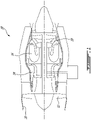
- FIG. 1 illustrates a gas turbine engine 10 of a turbo-fan type preferably provided for use in subsonic flight, generally comprising in serial flow communication a fan 12 through which ambient air is propelled, a multistage compressor 14 for pressurizing the air, a combustor 16 in which the compressed air is mixed with fuel and ignited for generating an annular stream of hot combustion gases, and a turbine section 18 for extracting energy from the combustion gases.
- Engine 10 may comprise one or more components 20 used as acoustic treatment (e.g., panels or liners) disposed at different locations within engine 10 to obtain desired noise-attenuation. It is understood that component 20 may be used in other types of engines (e.g., turbo-shaft, turboprop, auxiliary power unit (APU)) and in other types of noise-attenuating applications.
- APU auxiliary power unit
- one component 20 may be disposed upstream of fan 12 inside an inlet duct of engine 10 so that noise being produce by fan 12 may be attenuated.
- component 20 may be suitable for use in a fan case, intermediate case, bypass duct, exhaust duct, thrust reverser duct, exhaust bullet or center body of engine 10 for example.
- component 20 may be suitable for use in a hot core section duct of engine 10 where adhesively bonded acoustic materials cannot be used due to high temperatures.
- component 20 may have a generally planar or arcuate form (e.g., of single or double curvature).
- Component 20 may be a structural or parasitic part of a duct of a nose cowl of engine 10.
- FIG. 2 is a perspective cutaway view of an exemplary component 20 in the form of a single-degree-of-freedom (SDOF) acoustic panel 20A.
- SDOF acoustic panel 20A may comprise backing member 22, facing sheet 24 and cellular structure 26 (core) disposed between backing member 22 and facing sheet 24. Facing sheet 24 may be spaced apart from backing member 22 to define (e.g., noise-attenuating) cavity 28 between backing member 22 and facing sheet 24.
- cellular structure 26 may be attached to backing member 22 and/or facing sheet 24 by one or more non-adhesive or other type(s) of connections.
- Cellular structure 26 may comprise walls serving as partitions defining sub-cavities (cells) within noise-attenuating cavity 28.
- backing member 22 may have the form of a sheet and may be referred to as a "backing sheet". However, it is understood that backing member 22 may be of any suitable shape.
- backing member 22 may be a part of another component of engine 10 such as a wall of a bypass duct of engine 10 that provides a suitable back wall for noise-attenuating cavity 28.
- FIG. 3 is a perspective cutaway view of an exemplary component 20 in the form of double-degree-of-freedom (DDOF) acoustic panel 20B.
- DDOF acoustic panel 20B may comprise backing member 22, septum 32, cellular structures 26A, 26B and facing sheet 24. Septum 32 may be spaced apart from backing member 22 to define (e.g., noise-attenuating) cavity 28A between backing member 22 and septum 32.
- Cellular structure 26A may be disposed between backing member 22 and septum 32. As explained below, cellular structure 26A may be attached to backing member 22 and septum 32 by one or more non-adhesive or other type(s) of connections.
- Facing sheet 24 may be spaced apart from septum 32 to define (e.g., noise-attenuating) cavity 28B between septum 32 and facing sheet 24.
- Cellular structure 26B may be disposed between facing sheet 24 and septum 32.
- cellular structure 26B may be attached to facing sheet 24 and septum 32 by one or more non-adhesive or other type(s) of connections. Due to its configuration, DDOF acoustic panel 20B may be configured to resonate and attenuate noise at multiple frequencies or within a wider frequency range than SDOF acoustic panel 20A.
- cellular structures 26A, 26B may each comprise a plurality of open-ended juxtaposed cells of hexagonal or other (e.g., triangular, rectangular) crosssectional profile.
- the walls defining the cells of cellular structure 26 may extend from backing member 22 to facing sheet 24 and may provide support for facing sheet 24.
- the walls defining the cells of cellular structure 26B may extend from septum 32 to facing sheet 24, and the walls defining the cells of cellular structure 26A may extend from backing member 22 to septum 32.
- cellular structure 26 may be referred to as a "honeycomb" core.
- Cellular structure 26 may be made from a suitable non-metallic material (e.g., polymer), composite material (e.g., carbon fibre/resin matrix) or metallic (e.g., aluminum-based) material for example.
- Outer facing sheet 24 may be porous (e.g., perforated) and may comprise a plurality of through holes 30 formed therein. Facing sheet 24 may be made from a suitable composite material (e.g., carbon fibre with resin or ceramic matrix) or metallic (e.g., aluminum-based) material. In various embodiments, facing sheet 24 may comprise a wire mesh construction and/or may comprise felt metal.
- a suitable composite material e.g., carbon fibre with resin or ceramic matrix
- metallic e.g., aluminum-based
- Backing member 22 may be unperforated and comprise a non-porous impermeable sheet or other relatively hard material.
- Backing member 22 may be made from a suitable non-metallic material (e.g., polymer), composite material (e.g., carbon fibre/resin matrix) or metallic (e.g., aluminum-based) material for example.
- Septum 32 may be a porous (e.g., perforated) sheet and may comprise a plurality of through holes 34 formed therein for acoustically coupling noise-attenuating cavities 28A, 28B together.
- Septum 32 may be made from a suitable non-metallic material (e.g., polymer), composite material (e.g., carbon fibre/resin matrix) or metallic (e.g., aluminum-based) material for example.
- septum 32 may comprise a perforated sheet of similar of substantially the same construction as facing sheet 24.
- FIG. 4 is a flowchart of an exemplary method 100 for manufacturing component 20.
- method 100 may be used to manufacture SDOF acoustic panel 20A or DDOF acoustic panel 20B.
- Method 100 may comprise receiving parts of component 20 (see block 102) and assembling the parts of component 20 using one or more non-adhesive connections (see block 104).
- the parts of SDOF acoustic panel 20A may include backing member 22, porous facing sheet 24 and cellular structure 26. Assembling the parts may include assembling cellular structure 26 between backing member 22 and facing sheet 24 so that backing member 22 and facing sheet 24 are spaced apart to define noise-attenuating cavity 28 therebetween. Assembling cellular structure 26 between backing member 22 and facing sheet 24 may comprise attaching cellular structure 26 to facing sheet 24 using one or more non-adhesive connections.
- the parts of DDOF acoustic panel 20B may include backing member 22, porous facing sheet 24, porous septum (sheet) 32 and cellular structures 26A, 26B.
- Assembling the parts may include assembling cellular structure 26A between backing member 22 and septum 32 so that backing member 22 and septum 32 are spaced apart to define noise-attenuating cavity 28A therebetween.
- Assembling the parts may also include assembling cellular structure 26B between facing sheet 24 and septum 32 so that facing sheet 24 and septum 32 are spaced apart to define noise-attenuating cavity 28B therebetween.
- Assembling cellular structure 26A between backing member 22 and septum 32 may comprise attaching cellular structure 26A to backing member 22 using one or more non-adhesive connections and/or attaching cellular structure 26A to septum 32 using one or more non-adhesive connections.
- Assembling cellular structure 26B between facing sheet 24 and septum 32 may comprise attaching cellular structure 26B to facing sheet 24 using one or more non-adhesive connections and/or attaching cellular structure 26B to septum 32 using one or more non-adhesive connections.
- FIG. 5 is a perspective schematic view of an exemplary connection member 36 for providing a non-adhesive connection in component 20.
- Connection member 36 may be integrally-formed with or otherwise secured to backing member 22, facing sheet 24 or septum 32 of component 20.
- connection member 36 may be formed (i.e., built-up, grown, added) to backing member 22, facing sheet 24 or septum 32 using additive manufacturing or other suitable process(es).
- additive manufacturing may provide a relatively strong (e.g., metallurgical) bond between connection member 36 and backing member 22, facing sheet 24 or septum 32.
- connection member 36 may comprise a metallic (e.g., aluminum-based) material but it is understood that other types of (e.g., metallic and non-metallic) materials may also be suitable for connection member 36.
- one or more fasteners 38 may be provided on connection member 36 or elsewhere for providing corresponding non-adhesive connections between septum 32 and backing member 22 or facing sheet 24.
- fasteners 38 may be formed (i.e., built-up, grown, added) using additive manufacturing or other suitable process(es).
- Fasteners 38 may comprise the same or some other metallurgically compatible material as the material of connection member 36. Accordingly, fasteners 38 may be metallurgically bonded to connection member 36.
- Fasteners 38 may be generally pin-shaped and may be configured for frictional engagement with septum 32.
- fasteners 38 may be configured to pierce/rupture and penetrate septum 32, which may be relatively softer than fasteners 38, in order to provide some non-adhesive connections between septum 32 and backing member 22 or facing sheet 24 via connection member 36.
- a piercing end of each fastener 38 may be relatively sharp to facilitate piercing into septum 32.
- fastener 38 may be shaped like a nail.
- female receptor holes could be formed in septum 32 for receiving and frictionally engaging with fasteners 38 so as to form a sufficiently strong connection without necessarily using fasteners 38 to pierce/rupture septum 32.
- Connection member 36 comprises one or more slots 40 formed therein for providing a suitable non-adhesive connection between cellular structure 26 and backing member 22, facing sheet 24 or septum 32 via connection member 36.
- Slots 40 may be formed (e.g., grown) during the additive manufacturing process. Alternatively, slots 40 may be formed (e.g., cut, machined) into connection member 36 using a suitable material removal process after the forming of connection member 36 using additive manufacturing. Slots 40 are configured to engage with cellular structure 26 in order to provide suitable frictional engagement between cellular structure 26 and backing member 22, facing sheet 24 or septum 32 via connection member 36.
- connection member 36 may be mostly solid. In some embodiments, part(s) of connection member 36 may be hollow.
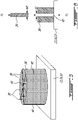
- FIG. 6 is a schematic representation of an exemplary process of establishing a non-adhesive connection between cellular structure 26 and connection member 36.
- one or more walls of cellular structure 26 may be inserted into and frictionally engaged with corresponding one or more slots 40 formed in connection member 36.
- the wall of cellular structure 26 may have a wall thickness WT and the corresponding slot 40 of connection member 36 may have a slot thickness ST.
- Wall thickness WT of cellular structure 26 and slot thickness ST of slot 40 may be selected to provide an interference fit, also known as a press fit, snap fit or friction fit between cellular structure 26 and connection member 36 in order to provide suitable attachment or fastening by friction after the parts are pushed together by the application of force F1.
- wall thickness WT may slightly exceed slot thickness ST.
- the tightness or strength of the fit achieved by the selection of wall thickness WT and slot thickness ST may provide a suitable attachment between cellular structure 26 and connection member 36 so that no other means of connection may be required between cellular structure 26 and connection member 36.
- the tightness or strength of the fit may be controlled by an amount of interference selected via wall thickness WT and slot thickness ST.
- the wall(s) of cellular structure 26 is frictionally retained in slot(s) 40 of connection member 36.
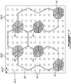
- FIG. 7 is a schematic representation of a plurality of connection members 36 providing non-adhesive connections between porous facing sheet 24 (or septum 32) and cellular structure 26 of component 20.
- Connection members 36 may be formed on facing sheet 24 or septum 32 using additive manufacturing as described above. The number, individual size and layout of connection members 36 on an inner side of facing sheet 24 or on septum 32 may be selected to provide the desired attachment/retention of cellular structure 26 with facing sheet 24 or with septum 32.
- slot(s) 40 (see FIG. 5 ) of one or more connection members 36 may be configured to receive therein only a straight wall portion of cellular structure 26.
- connection members 36 may be configured to receive therein part of two or more intersecting and non-parallel walls of cellular structure 26.
- connection members 36 may each comprise one or a plurality of linear slots 40.
- such slots 40 may have orientations corresponding to the relative orientations of adjacent intersecting walls of cellular structure 26 so that intersecting portions of cellular structure 26 may be received in slot(s) 40 and thereby frictionally engaged with corresponding connection members 36 as shown in FIG. 7 .
- one or more connection members 36 may each frictionally engage part of three adjacent cells of cellular structure 26.
- connection members 36 and cellular structure 26 may be used in the manufacturing of SDOF acoustic panel 20A or of DDOF acoustic panel 20B.
- FIG. 8 is a schematic elevation view of an exemplary SDOF acoustic panel 20A comprising non-adhesive connections between cellular structure 26 and porous facing sheet 24 provided by connection members 36. Facing sheet 24 may be spaced apart from backing member 22 to define noise-attenuating cavity 28 therebetween.
- SDOF acoustic panel 20A may be manufactured using one or more non-adhesive connections and also using one or more adhesive connections.
- a suitable adhesive substance 42 e.g., epoxy resin adhesive, glue
- an adhesive reticulation process using a suitable film adhesive may be used to form one or more adhesive connections between cellular structure 26 and backing member 22.
- connection members 36 from facing sheet 24 may be less than a thickness of cellular structure 26 and hence less than a height h1 of noise-attenuating cavity 28 since connection members 36 are not used to attach cellular structure 26 to backing member 22.
- the height of connection members 36 may be selected to frictionally engage a desired amount/height of cellular structure 26 to provide the desired amount of retention.
- fasteners 38 shown in FIG. 5 may not be required. Accordingly, connection members 36 may be formed without any fasteners 38 extending therefrom in some embodiments.
- SDOF acoustic panel 20A may be configured to resonate and attenuate noise at a single frequency or within a narrow frequency range.
- one or more holes 30 may be in communication with each cell defined by cellular structure 26 and each cell may function as a Helmholtz resonant cavity.
- Noise-attenuating cavity 28 of SDOF acoustic panel 20A may have a height h1 and facing sheet 24 may have a thickness t1.
- Holes 30 extending through facing sheet 24 may each have a diameter d1.
- Structural parameters of SDOF acoustic panel 20A such as height h1, diameter d1 of holes 30 and thickness t1 of facing sheet 24 may be selected to obtain desired noise-attenuation properties.
- a highly resistive material such as a mesh of porous material may be disposed inside the cells defined by cellular structure 26 in cavity 28 and may alter the noise-attenuating performance of acoustic panel 20A.
- the use of such highly resistive material may cause acoustic panel 20A to have a noise-attenuating performance that is more similar to that of a DDOF acoustic panel even though it has a SDOF acoustic panel construction.
- FIGS. 9-12 relate to the manufacturing of DDOF acoustic panel 20B using one or more non-adhesive connections.
- DDOF acoustic panel 20B may comprise connection members 36 on both backing member 22 and facing sheet 24.
- reference character 36A is used to denote connection members secured to backing member 22
- reference character 36B is used to denote connection members secured to facing sheet 24.
- reference character 38A is used to denote fasteners secured to backing member 22 via connection members 36A
- reference character 38B is used to denote fasteners secured to facing sheet 24 via connection members 36B.
- FIG. 9 is a schematic representation of a plurality of connection members 36A providing non-adhesive connections between backing member 22 and cellular structure 26A of DDOF acoustic panel 20B. Details of the configuration and manufacturing of the arrangement of FIG. 9 can be similar to that described above in relation to facing sheet 24 and the arrangement of FIG. 7 .
- Connection members 36A may be formed on backing member 22 using additive manufacturing or other suitable manufacturing process.
- the upper assembly including facing sheet 24, connection members 36 and cellular structure 26 as shown in FIG. 7 may be used in conjunction with the lower assembly including backing member 22, connection members 36A and cellular structure 26A shown in FIG. 9 .
- the assembly of FIG. 9 In contrast with the assembly of FIG.
- connection members 36B may span a greater portion of the thickness of cellular structure 26B (see FIG. 11 ).
- the height of connection members 36B may be substantially the same as the thickness (e.g., height h2) of cellular structure 26B.
- connection members 36B of the upper assembly may be provided with fasteners 38B similar to those shown in FIG. 9 .
- the height of connection members 36A may be substantially the same as the thickness (e.g., height h1) of cellular structure 26A.
- cellular structures 26A, 26B may have different configurations including different heights and/or cell sizes for example.
- FIG. 10 is a schematic representation of a process for forming non-adhesive connections between connection member 36B and septum 32 via fasteners 38B and for forming non-adhesive connections between connection member 36A and septum 32 via fasteners 38A.
- fasteners 38A, 38B may be used to provide non-adhesive connection(s) between the upper assembly comprising facing sheet 24 and cellular structure 26B, and, the lower assembly comprising backing member 22 and cellular structure 26A.
- septum 32 The material and thickness of septum 32 may be selected so that septum 32 may be penetrated/ruptured by fasteners 38A as connection member 36A is pressed against septum 32, and by fasteners 38B as connection member 36B is pressed against septum 32.
- FIG. 10 shows opposite connection members 36A, 36B being simultaneously urged toward septum 32 from opposite sides of septum 32 by the application of force F2 but it is understood that connection members 36A, 36B may be urged toward septum 32 at different times.
- connection members 36A, 36B may cause the corresponding fasteners 38A, 38B to penetrate septum 32 from opposite sides and thereby frictionally engage (e.g., become anchored) with septum 32 so as to form suitable non-adhesive connections with septum 32.
- female receptor holes could be formed in septum 32 for receiving and frictionally engaging with fasteners 38 so as to form a sufficiently strong connection without necessarily using fasteners 38 to pierce/rupture septum 32.
- FIG. 11 is a schematic elevation view of an exemplary DDOF acoustic panel 20B comprising non-adhesive connections.
- DDOF acoustic panel 20B may comprise the following:
- Connection members 36A may be secured (e.g., metallurgically bonded) to backing member 22 and frictionally engaged with cellular structure 26A (e.g., via slots 40).
- connection members 36B may be secured (e.g., metallurgically bonded) to facing sheet 24 and frictionally engaged with cellular structure 26B (e.g., via slots 40).
- Fasteners 38A may be secured (e.g., metallurgically bonded) to connection members 36A and frictionally engaged with septum 32.
- Fasteners 38B may be secured (e.g., metallurgically bonded) to connection members 36B and frictionally engaged with septum 32.
- FIG. 12 is a schematic elevation view of another exemplary DDOF acoustic panel 20B comprising non-adhesive connections.
- connection members 36A, 36B could be added to opposite sides of septum 32 using additive manufacturing for the purpose of providing a frictional engagement with corresponding cellular structures 26A, 26B.
- cellular structure 26A could be attached to backing plate 22 using adhesive reticulation (e.g., see adhesive substance 42A) and cellular structure 26B could be attached to facing plate 24 using adhesive reticulation (e.g., see adhesive substance 42B).
- adhesive reticulation could potentially cause some holes 30 of facing sheet 24 to be blocked by adhesive material but any blocked holes 30 could potentially be subsequently cleared using a jet of compressed air for example.
- DDOF acoustic panel 20B may be configured to resonate and attenuate noise at multiple frequencies or within a wider frequency range compared to SDOF acoustic panel 20A.
- one or more holes 30 in facing sheet 24 may be in communication with each cell defined by cellular structure 26B of noise-attenuating cavity 28B and each cell of noise-attenuating cavity 28B may function as a Helmholtz resonant cavity.
- Noise-attenuating cavity 28A may be in acoustic communication with noise-attenuating cavity 28B via holes 34 extending through septum 32 (see FIG. 10 ).
- Each cell defined by cellular structure 26A of noise-attenuating cavity 28A may also function as a Helmholtz resonant cavity.
- Noise-attenuating cavity 28A may have a height h1
- noise-attenuating cavity 28B may have a height h2
- facing sheet 24 may have a thickness t1
- septum 32 may have a thickness t2.
- Holes 30 in facing sheet 24 may each have a diameter d1 (see FIG. 7 ).
- Holes 34 in septum 32 may each have a diameter d2 (see FIG. 10 ).
- Structural parameters of DDOF acoustic panel 20A such as heights h1 and h2, diameters d1 and d2 of holes 30 and 34 respectively, thickness t1 of facing sheet 24 and thickness t2 of septum 32 may be selected to obtain desired noise-attenuation properties.
- DDOF acoustic panels 20B may be manufactured as "drop-in" units/components outside of engine 10 (or nacelle) and that are ready to be inserted into suitable slots in engine 10. Such construction of DDOF acoustic panels 20B may facilitate installation and replacement of DDOF acoustic panels in the structure of engine 10.
Landscapes
- Engineering & Computer Science (AREA)
- Chemical & Material Sciences (AREA)
- Physics & Mathematics (AREA)
- Combustion & Propulsion (AREA)
- Acoustics & Sound (AREA)
- Mechanical Engineering (AREA)
- Architecture (AREA)
- General Engineering & Computer Science (AREA)
- Ceramic Engineering (AREA)
- Electromagnetism (AREA)
- Civil Engineering (AREA)
- Structural Engineering (AREA)
- Multimedia (AREA)
- Manufacturing & Machinery (AREA)
- Materials Engineering (AREA)
- Health & Medical Sciences (AREA)
- Chemical Kinetics & Catalysis (AREA)
- Medicinal Chemistry (AREA)
- Polymers & Plastics (AREA)
- Organic Chemistry (AREA)
- Soundproofing, Sound Blocking, And Sound Damping (AREA)
Claims (15)
- Flugzeugbauteil (20), das Folgendes umfasst:ein Trägerelement (22);eine poröse Schicht (24, 32), die von dem Trägerelement (22) beabstandet ist, um einen Hohlraum (28; 28A, 28B) zwischen dem Trägerelement (22) und der porösen Schicht (24; 32) zu definieren; undeine zellulare Struktur (26; 26A, 26B), die zwischen dem Trägerelement (22) und der porösen Schicht (24, 32) angeordnet ist, wobei die zellulare Struktur (26; 26A, 26B) an dem Trägerelement (22) und/oder der porösen Schicht (24, 32) durch eine oder mehrere nicht-klebende Verbindungen angebracht ist,dadurch gekennzeichnet, dass das Flugzeugbauteil (20) ferner Folgendes umfasst:
ein Verbindungselement (36), das an dem Trägerelement (22) oder an der porösen Schicht (24, 32) befestigt ist, wobei das Verbindungselement (36) einen Schlitz (40) beinhaltet und eine Wand der zellularen Struktur (26;26A,26B) durch Reibung in dem Schlitz (40) des Verbindungselements (36) gehalten wird. - Flugzeugbauteil (20) nach Anspruch 1, wobei die poröse Schicht (24) eine Deckschicht (24) des Flugzeugbauteils (20) ist und die zellulare Struktur (26; 26A, 26B) über die eine oder mehreren nicht-klebenden Verbindungen an der Deckschicht (24) angebracht ist.
- Flugzeugbauteil (20) nach Anspruch 2, wobei das Verbindungselement (36) an der Deckschicht (24) befestigt ist und wobei optional das Verbindungselement (36) metallurgisch an die Deckschicht (24) gebondet ist.
- Flugzeugbauteil (20) nach Anspruch 2 oder 3, ferner umfassend eine Trennwand (32), die zwischen zwei Hohlräumen (28A, 28B) angeordnet ist, die zwischen dem Trägerelement (22) und der Deckschicht (24) des Flugzeugbauteils (20) definiert sind, wobei die zellulare Struktur (26A, 26B) über die eine oder mehreren nicht-klebenden Verbindungen an der Trennwand (32) angebracht ist.
- Flugzeugbauteil (20) nach Anspruch 4, umfassend ein Befestigungselement (38), das an der Deckschicht (24) befestigt ist und durch Reibung mit der Trennwand (32) in Eingriff steht, wobei optional das Befestigungselement (38) die Trennwand (32) durchdringt.
- Flugzeugbauteil (20) nach Anspruch 1, wobei die zellulare Struktur (28A, 28B) über die eine oder mehreren nicht-klebenden Verbindungen an dem Trägerelement (22) angebracht ist.
- Flugzeugbauteil (20) nach Anspruch 6, wobei das Verbindungselement (36) an dem Trägerelement (22) befestigt ist, wobei optional das Verbindungselement (36) metallurgisch an das Trägerelement (22) gebondet ist.
- Flugzeugbauteil (20) nach Anspruch 6 oder 7, wobei die poröse Schicht (32) eine Trennwand (32) ist, die zwischen zwei Hohlräumen (28A, 28B) des Flugzeugbauteils (20) angeordnet ist, wobei die zellulare Struktur (26A, 26B) über die eine oder mehrere nicht-klebende Verbindungen an der Trennwand (32) angebracht ist, optional umfassend ein Befestigungselement (38), das an dem Trägerelement (22) befestigt ist und durch Reibung mit der Trennwand (32) in Eingriff steht.
- Flugzeugbauteil (20) nach Anspruch 1, wobei die poröse Schicht (32) eine Trennwand (32) ist, der Hohlraum (28A) ein erster Hohlraum (28A) ist, die zellulare Struktur (26A) eine erste zellulare Struktur (26A) ist, die eine oder mehreren nicht-klebenden Verbindungen eine oder mehrere erste nicht-klebende Verbindungen sind und das Flugzeugbauteil (20) ferner Folgendes umfasst:eine Deckschicht (24), die von der Trennwand (32) beabstandet ist, um einen zweiten Hohlraum (28B) zwischen der Trennwand (32) und der Deckschicht (24) zu definieren; undeine zweite zellulare Struktur (26B), die zwischen der Trennwand (32) und der Deckschicht (24) angeordnet ist, wobei die zweite zellulare Struktur (26B) durch eine oder mehrere zweite nicht-klebende Verbindungen an mindestens einer von der Trennwand (32) und der Deckschicht (24) angebracht ist.
- Flugzeugbauteil (20) nach Anspruch 9, wobei:das Verbindungselement (36) ein erstes Verbindungselement (36) ist; unddas Flugzeugbauteil (20) ein zweites Verbindungselement (36) umfasst, das an der Deckschicht (24) befestigt ist und durch Reibung mit der zweiten zellularen Struktur (26B) in Eingriff steht, wobei optional das erste Verbindungselement (36) metallurgisch an das Trägerelement (22) gebondet ist und das zweite Verbindungselement (36) metallurgisch an die Deckschicht (24) gebondet ist.
- Flugzeugbauteil (20) nach Anspruch 10, umfassend:ein erstes Befestigungselement (38), das metallurgisch an das erste Verbindungselement (36) gebondet ist und durch Reibung mit der Trennwand (32) in Eingriff steht; undein zweites Befestigungselement (38), das metallurgisch an das zweite Verbindungselement (36) gebondet ist und durch Reibung mit der Trennwand (32) in Eingriff steht.
- Verfahren zum Herstellen eines Flugzeugbauteils (20), wobei das Verfahren Folgendes umfasst:Aufnehmen eines Trägerelements (22), einer porösen Schicht (24, 32) und einer zellularen Struktur (26; 26A, 26B); undMontieren der zellularen Struktur (26; 26A, 26B) zwischen dem Trägerelement (22) und der porösen Schicht (24, 32), sodass das Trägerelement (22) und die poröse Schicht (24, 32) voneinander beabstandet sind, um einen Hohlraum (28; 28A, 28B) dazwischen zu definieren, wobei das Montieren der zellularen Struktur (26;26A, 26B) zwischen dem Trägerelement (22) und der porösen Schicht (24, 32) Anbringen der zellularen Struktur (26; 26A, 26B) an mindestens einem von dem Trägerelement (22) und der porösen Schicht (24, 32) unter Verwendung einer oder mehrerer nicht-klebenden Verbindungen umfasst, dadurch gekennzeichnet, dass das Verfahren ferner Folgendes umfasst:
Halten einer Wand der zellularen Struktur (26; 26A, 26B) durch Reibung in einem Schlitz (40) eines Verbindungselements (36), wobei das Verbindungselement (36) an dem Trägerelement (22) oder an der porösen Schicht (24, 32) befestigt ist. - Verfahren nach Anspruch 12, umfassend Verwenden von additiver Fertigung, um das Verbindungselement (36) auf dem Trägerelement (22) oder auf der porösen Schicht (24; 32) auszubilden.
- Verfahren nach Anspruch 12, wobei die poröse Schicht (32) eine Trennwand (32) zum Montieren zwischen zwei Hohlräumen (28A, 28B) ist, die zwischen dem Trägerelement (22) und einer Deckschicht (24) des Flugzeugbauteils (20) definiert sind, die zellulare Struktur (26A) eine erste zellulare Struktur (26A) zum Montieren zwischen der Trennwand (32) und dem Trägerelement (22) ist, das Verbindungselement (36) ein erstes Verbindungselement (32) ist und wobei das Verfahren ferner Folgendes umfasst:Verwenden von additiver Fertigung, um das erste Verbindungselement (36) auf dem Trägerelement (22) auszubilden;Ineingriffnehmen der ersten zellularen Struktur (26A) mit dem ersten Verbindungselement (36) durch Reibung;Aufnehmen der Deckschicht (22);Verwenden von additiver Fertigung, um ein zweites Verbindungselement (36) auf der Deckschicht (22) auszubilden;Aufnehmen einer zweiten zellularen Struktur (26B) zum Montieren zwischen der Trennwand (32) und der Deckschicht (24); undIneingriffnehmen der zweiten zellularen Struktur (26B) mit dem zweiten Verbindungselement (36) durch Reibung.
- Verfahren nach Anspruch 14, das ferner Folgendes umfasst:Verwenden von additiver Fertigung, um ein erstes Befestigungselement (38) auf dem ersten Verbindungselement (36) und ein zweites Befestigungselement (38) auf dem zweiten Verbindungselement (36) auszubilden; undIneingriffnehmen des ersten und zweiten Befestigungselements (38) mit der Trennwand (32) durch Reibung.
Applications Claiming Priority (1)
| Application Number | Priority Date | Filing Date | Title |
|---|---|---|---|
| US15/938,371 US11092077B2 (en) | 2018-03-28 | 2018-03-28 | Aircraft component and method of manufacture |
Publications (2)
| Publication Number | Publication Date |
|---|---|
| EP3546209A1 EP3546209A1 (de) | 2019-10-02 |
| EP3546209B1 true EP3546209B1 (de) | 2022-12-28 |
Family
ID=66001068
Family Applications (1)
| Application Number | Title | Priority Date | Filing Date |
|---|---|---|---|
| EP19165954.9A Active EP3546209B1 (de) | 2018-03-28 | 2019-03-28 | Flugzeugbauteil und verfahren zur herstellung |
Country Status (3)
| Country | Link |
|---|---|
| US (1) | US11092077B2 (de) |
| EP (1) | EP3546209B1 (de) |
| CA (1) | CA3032167A1 (de) |
Families Citing this family (15)
| Publication number | Priority date | Publication date | Assignee | Title |
|---|---|---|---|---|
| GB201811549D0 (en) * | 2018-07-13 | 2018-08-29 | Rolls Royce Plc | Fan blade containment |
| FR3094668A1 (fr) * | 2019-04-02 | 2020-10-09 | Airbus Operations | Assemblage constituant un matériau acoustiquement absorbant |
| WO2021116889A1 (en) * | 2019-12-12 | 2021-06-17 | 3M Innovative Properties Company | Methods of making dual layer sound-absorbing panels comprising a core consisting of connected cells, wherein some of the cell walls have openings |
| WO2021116888A1 (en) * | 2019-12-12 | 2021-06-17 | 3M Innovative Properties Company | Dual layer sound-absorbing panels comprising a core consisting of connected cells, wherein some of the cell walls have openings |
| CN111113889B (zh) * | 2019-12-22 | 2021-06-04 | 同济大学 | 一种使用带芯线材的熔融沉积成型方法 |
| US11680542B2 (en) * | 2020-02-03 | 2023-06-20 | Rohr, Inc. | Thrust reverser door and method for making same |
| US11339720B2 (en) | 2020-02-21 | 2022-05-24 | Raytheon Technologies Corporation | Acoustic liner with non-uniform volumetric distribution |
| CN113803296A (zh) * | 2020-06-16 | 2021-12-17 | 中国航发商用航空发动机有限责任公司 | 航空发动机、声衬、声衬孔板及声衬孔板的制造方法 |
| US12136407B2 (en) | 2020-11-02 | 2024-11-05 | Pratt & Whitney Canada Corp. | Sandwich-structured panels and method of manufacture |
| US11867077B2 (en) * | 2021-06-07 | 2024-01-09 | Rohr, Inc. | Acoustic structure with floating interior skin |
| US11674405B2 (en) * | 2021-08-30 | 2023-06-13 | General Electric Company | Abradable insert with lattice structure |
| US12142253B2 (en) * | 2021-10-05 | 2024-11-12 | General Electric Company | Solid adhesive film for acoustic liner and method |
| US12006874B2 (en) * | 2022-02-14 | 2024-06-11 | Rolls-Royce Corporation | 3D printed acoustic panel with lattice structure support layer |
| US12136408B2 (en) * | 2022-04-29 | 2024-11-05 | Rolls-Royce Corporation | Acoustic panel with 3D printed cell structure support layer |
| GB202214882D0 (en) | 2022-10-10 | 2022-11-23 | Rolls Royce Plc | Curing and bonding tool |
Family Cites Families (16)
| Publication number | Priority date | Publication date | Assignee | Title |
|---|---|---|---|---|
| US3526072A (en) * | 1968-03-29 | 1970-09-01 | James R Campbell | Load distributing system for panels incorporating honeycomb core |
| US3910374A (en) * | 1974-03-18 | 1975-10-07 | Rohr Industries Inc | Low frequency structural acoustic attenuator |
| US4271219A (en) * | 1979-10-02 | 1981-06-02 | Rohr Industries, Inc. | Method of manufacturing an adhesive bonded acoustical attenuation structure and the resulting structure |
| US5041323A (en) * | 1989-10-26 | 1991-08-20 | Rohr Industries, Inc. | Honeycomb noise attenuation structure |
| US5460865A (en) * | 1993-05-13 | 1995-10-24 | Ciba-Geigy Corporation | Hybrid honeycomb sandwich panel |
| US6203656B1 (en) * | 1998-08-03 | 2001-03-20 | General Electric Company | Acoustic liner manufacture |
| FR2815900B1 (fr) * | 2000-10-31 | 2003-07-18 | Eads Airbus Sa | Panneau sandwich reducteur de bruit, notamment pour turboreacteur d'aeronef |
| US6871725B2 (en) | 2003-02-21 | 2005-03-29 | Jeffrey Don Johnson | Honeycomb core acoustic unit with metallurgically secured deformable septum, and method of manufacture |
| US8070994B2 (en) | 2004-06-18 | 2011-12-06 | Zephyros, Inc. | Panel structure |
| FR2933224B1 (fr) * | 2008-06-25 | 2010-10-29 | Aircelle Sa | Panneau accoustique pour une tuyere d'ejection |
| FR2965859B1 (fr) * | 2010-10-07 | 2012-11-02 | Snecma | Dispositif de traitement acoustique du bruit emis par un turboreacteur |
| FR2970900B1 (fr) * | 2011-01-31 | 2013-10-18 | Aircelle Sa | Procede de reparation d'un panneau d'attenuation acoustique |
| US8763753B2 (en) * | 2012-02-10 | 2014-07-01 | General Electric Company | Acoustic panel and method of forming |
| US8820477B1 (en) * | 2013-07-29 | 2014-09-02 | The Boeing Company | Acoustic panel |
| US9127452B1 (en) | 2014-04-11 | 2015-09-08 | Rohr, Inc. | Porous septum cap |
| US9447576B2 (en) | 2015-01-09 | 2016-09-20 | Rohr, Inc. | Post bond perforation of a septum in an acoustic panel |
-
2018
- 2018-03-28 US US15/938,371 patent/US11092077B2/en active Active
-
2019
- 2019-01-31 CA CA3032167A patent/CA3032167A1/en active Pending
- 2019-03-28 EP EP19165954.9A patent/EP3546209B1/de active Active
Also Published As
| Publication number | Publication date |
|---|---|
| CA3032167A1 (en) | 2019-09-28 |
| EP3546209A1 (de) | 2019-10-02 |
| US11092077B2 (en) | 2021-08-17 |
| US20190301370A1 (en) | 2019-10-03 |
Similar Documents
| Publication | Publication Date | Title |
|---|---|---|
| EP3546209B1 (de) | Flugzeugbauteil und verfahren zur herstellung | |
| EP3564508B1 (de) | Flugzeugantriebssystemanordnung mit einer oder mehreren akustischen platten | |
| EP3991948B1 (de) | Sandwichstrukturierte platten und verfahren zur herstellung | |
| EP3489947B1 (de) | Akustikplatte mit strukturellem septum | |
| EP3324400B1 (de) | Akustikplatte mit seitenwandholmen | |
| EP3447760B1 (de) | Verfahren zur formung einer bauplatte | |
| US6203656B1 (en) | Acoustic liner manufacture | |
| EP3259125B1 (de) | Schalldämpfende auskleidungen und verfahren zur formgebung eines einlasses einer schalldämpfenden auskleidung | |
| JP6223559B2 (ja) | 気流によるノイズの減衰のための超塑性成形/拡散接合構造体 | |
| EP2240317B1 (de) | Triebwerk mit einer Wabenstruktur and entsprechendes Herstellungsverfahren | |
| US20140077031A1 (en) | Metallic sandwich structure having small bend radius | |
| CN101898639A (zh) | 带裂纹和分层制止器的飞机发动机舱的声匣 | |
| EP2530016A2 (de) | Flugzeugtriebwerksverkleidung und Verfahren dafür | |
| EP2538137B1 (de) | Brennkammer mit dehnungstoleranter Brennkammerplatte für Gasturbinenmotor | |
| US12264625B2 (en) | Acoustic attenuation panel and its manufacturing methods | |
| US20180082671A1 (en) | Acoustic liner and methods of constructing an acoustic liner | |
| EP3053953A1 (de) | Offenzelliger netzartiger schaum | |
| EP4108443A1 (de) | Akustikplatte und verfahren zu deren bildung | |
| EP3231598B1 (de) | Verfahren zur herstellung einer leichten komponente mit schalldämpfung | |
| US12312969B2 (en) | Airfoils for turbofan engines | |
| EP3858595A1 (de) | Akustische auskleidung und verfahren zur herstellung derselben | |
| CN116713473A (zh) | 具有增材制造的金属制品的金属结构和制造方法 |
Legal Events
| Date | Code | Title | Description |
|---|---|---|---|
| PUAI | Public reference made under article 153(3) epc to a published international application that has entered the european phase |
Free format text: ORIGINAL CODE: 0009012 |
|
| STAA | Information on the status of an ep patent application or granted ep patent |
Free format text: STATUS: THE APPLICATION HAS BEEN PUBLISHED |
|
| AK | Designated contracting states |
Kind code of ref document: A1 Designated state(s): AL AT BE BG CH CY CZ DE DK EE ES FI FR GB GR HR HU IE IS IT LI LT LU LV MC MK MT NL NO PL PT RO RS SE SI SK SM TR |
|
| AX | Request for extension of the european patent |
Extension state: BA ME |
|
| STAA | Information on the status of an ep patent application or granted ep patent |
Free format text: STATUS: REQUEST FOR EXAMINATION WAS MADE |
|
| 17P | Request for examination filed |
Effective date: 20200331 |
|
| RBV | Designated contracting states (corrected) |
Designated state(s): AL AT BE BG CH CY CZ DE DK EE ES FI FR GB GR HR HU IE IS IT LI LT LU LV MC MK MT NL NO PL PT RO RS SE SI SK SM TR |
|
| STAA | Information on the status of an ep patent application or granted ep patent |
Free format text: STATUS: EXAMINATION IS IN PROGRESS |
|
| 17Q | First examination report despatched |
Effective date: 20200511 |
|
| GRAP | Despatch of communication of intention to grant a patent |
Free format text: ORIGINAL CODE: EPIDOSNIGR1 |
|
| STAA | Information on the status of an ep patent application or granted ep patent |
Free format text: STATUS: GRANT OF PATENT IS INTENDED |
|
| INTG | Intention to grant announced |
Effective date: 20220712 |
|
| GRAS | Grant fee paid |
Free format text: ORIGINAL CODE: EPIDOSNIGR3 |
|
| GRAA | (expected) grant |
Free format text: ORIGINAL CODE: 0009210 |
|
| STAA | Information on the status of an ep patent application or granted ep patent |
Free format text: STATUS: THE PATENT HAS BEEN GRANTED |
|
| AK | Designated contracting states |
Kind code of ref document: B1 Designated state(s): AL AT BE BG CH CY CZ DE DK EE ES FI FR GB GR HR HU IE IS IT LI LT LU LV MC MK MT NL NO PL PT RO RS SE SI SK SM TR |
|
| REG | Reference to a national code |
Ref country code: GB Ref legal event code: FG4D |
|
| REG | Reference to a national code |
Ref country code: CH Ref legal event code: EP |
|
| REG | Reference to a national code |
Ref country code: DE Ref legal event code: R096 Ref document number: 602019023573 Country of ref document: DE |
|
| REG | Reference to a national code |
Ref country code: AT Ref legal event code: REF Ref document number: 1540208 Country of ref document: AT Kind code of ref document: T Effective date: 20230115 |
|
| REG | Reference to a national code |
Ref country code: IE Ref legal event code: FG4D |
|
| REG | Reference to a national code |
Ref country code: LT Ref legal event code: MG9D |
|
| PG25 | Lapsed in a contracting state [announced via postgrant information from national office to epo] |
Ref country code: SE Free format text: LAPSE BECAUSE OF FAILURE TO SUBMIT A TRANSLATION OF THE DESCRIPTION OR TO PAY THE FEE WITHIN THE PRESCRIBED TIME-LIMIT Effective date: 20221228 Ref country code: NO Free format text: LAPSE BECAUSE OF FAILURE TO SUBMIT A TRANSLATION OF THE DESCRIPTION OR TO PAY THE FEE WITHIN THE PRESCRIBED TIME-LIMIT Effective date: 20230328 Ref country code: LT Free format text: LAPSE BECAUSE OF FAILURE TO SUBMIT A TRANSLATION OF THE DESCRIPTION OR TO PAY THE FEE WITHIN THE PRESCRIBED TIME-LIMIT Effective date: 20221228 Ref country code: FI Free format text: LAPSE BECAUSE OF FAILURE TO SUBMIT A TRANSLATION OF THE DESCRIPTION OR TO PAY THE FEE WITHIN THE PRESCRIBED TIME-LIMIT Effective date: 20221228 |
|
| REG | Reference to a national code |
Ref country code: NL Ref legal event code: MP Effective date: 20221228 |
|
| REG | Reference to a national code |
Ref country code: AT Ref legal event code: MK05 Ref document number: 1540208 Country of ref document: AT Kind code of ref document: T Effective date: 20221228 |
|
| PG25 | Lapsed in a contracting state [announced via postgrant information from national office to epo] |
Ref country code: RS Free format text: LAPSE BECAUSE OF FAILURE TO SUBMIT A TRANSLATION OF THE DESCRIPTION OR TO PAY THE FEE WITHIN THE PRESCRIBED TIME-LIMIT Effective date: 20221228 Ref country code: LV Free format text: LAPSE BECAUSE OF FAILURE TO SUBMIT A TRANSLATION OF THE DESCRIPTION OR TO PAY THE FEE WITHIN THE PRESCRIBED TIME-LIMIT Effective date: 20221228 Ref country code: HR Free format text: LAPSE BECAUSE OF FAILURE TO SUBMIT A TRANSLATION OF THE DESCRIPTION OR TO PAY THE FEE WITHIN THE PRESCRIBED TIME-LIMIT Effective date: 20221228 Ref country code: GR Free format text: LAPSE BECAUSE OF FAILURE TO SUBMIT A TRANSLATION OF THE DESCRIPTION OR TO PAY THE FEE WITHIN THE PRESCRIBED TIME-LIMIT Effective date: 20230329 |
|
| PG25 | Lapsed in a contracting state [announced via postgrant information from national office to epo] |
Ref country code: NL Free format text: LAPSE BECAUSE OF FAILURE TO SUBMIT A TRANSLATION OF THE DESCRIPTION OR TO PAY THE FEE WITHIN THE PRESCRIBED TIME-LIMIT Effective date: 20221228 |
|
| P01 | Opt-out of the competence of the unified patent court (upc) registered |
Effective date: 20230530 |
|
| PG25 | Lapsed in a contracting state [announced via postgrant information from national office to epo] |
Ref country code: SM Free format text: LAPSE BECAUSE OF FAILURE TO SUBMIT A TRANSLATION OF THE DESCRIPTION OR TO PAY THE FEE WITHIN THE PRESCRIBED TIME-LIMIT Effective date: 20221228 Ref country code: RO Free format text: LAPSE BECAUSE OF FAILURE TO SUBMIT A TRANSLATION OF THE DESCRIPTION OR TO PAY THE FEE WITHIN THE PRESCRIBED TIME-LIMIT Effective date: 20221228 Ref country code: PT Free format text: LAPSE BECAUSE OF FAILURE TO SUBMIT A TRANSLATION OF THE DESCRIPTION OR TO PAY THE FEE WITHIN THE PRESCRIBED TIME-LIMIT Effective date: 20230428 Ref country code: ES Free format text: LAPSE BECAUSE OF FAILURE TO SUBMIT A TRANSLATION OF THE DESCRIPTION OR TO PAY THE FEE WITHIN THE PRESCRIBED TIME-LIMIT Effective date: 20221228 Ref country code: EE Free format text: LAPSE BECAUSE OF FAILURE TO SUBMIT A TRANSLATION OF THE DESCRIPTION OR TO PAY THE FEE WITHIN THE PRESCRIBED TIME-LIMIT Effective date: 20221228 Ref country code: CZ Free format text: LAPSE BECAUSE OF FAILURE TO SUBMIT A TRANSLATION OF THE DESCRIPTION OR TO PAY THE FEE WITHIN THE PRESCRIBED TIME-LIMIT Effective date: 20221228 Ref country code: AT Free format text: LAPSE BECAUSE OF FAILURE TO SUBMIT A TRANSLATION OF THE DESCRIPTION OR TO PAY THE FEE WITHIN THE PRESCRIBED TIME-LIMIT Effective date: 20221228 |
|
| PG25 | Lapsed in a contracting state [announced via postgrant information from national office to epo] |
Ref country code: SK Free format text: LAPSE BECAUSE OF FAILURE TO SUBMIT A TRANSLATION OF THE DESCRIPTION OR TO PAY THE FEE WITHIN THE PRESCRIBED TIME-LIMIT Effective date: 20221228 Ref country code: PL Free format text: LAPSE BECAUSE OF FAILURE TO SUBMIT A TRANSLATION OF THE DESCRIPTION OR TO PAY THE FEE WITHIN THE PRESCRIBED TIME-LIMIT Effective date: 20221228 Ref country code: IS Free format text: LAPSE BECAUSE OF FAILURE TO SUBMIT A TRANSLATION OF THE DESCRIPTION OR TO PAY THE FEE WITHIN THE PRESCRIBED TIME-LIMIT Effective date: 20230428 Ref country code: AL Free format text: LAPSE BECAUSE OF FAILURE TO SUBMIT A TRANSLATION OF THE DESCRIPTION OR TO PAY THE FEE WITHIN THE PRESCRIBED TIME-LIMIT Effective date: 20221228 |
|
| REG | Reference to a national code |
Ref country code: DE Ref legal event code: R097 Ref document number: 602019023573 Country of ref document: DE |
|
| PG25 | Lapsed in a contracting state [announced via postgrant information from national office to epo] |
Ref country code: MC Free format text: LAPSE BECAUSE OF FAILURE TO SUBMIT A TRANSLATION OF THE DESCRIPTION OR TO PAY THE FEE WITHIN THE PRESCRIBED TIME-LIMIT Effective date: 20221228 Ref country code: DK Free format text: LAPSE BECAUSE OF FAILURE TO SUBMIT A TRANSLATION OF THE DESCRIPTION OR TO PAY THE FEE WITHIN THE PRESCRIBED TIME-LIMIT Effective date: 20221228 |
|
| REG | Reference to a national code |
Ref country code: CH Ref legal event code: PL |
|
| PLBE | No opposition filed within time limit |
Free format text: ORIGINAL CODE: 0009261 |
|
| STAA | Information on the status of an ep patent application or granted ep patent |
Free format text: STATUS: NO OPPOSITION FILED WITHIN TIME LIMIT |
|
| REG | Reference to a national code |
Ref country code: BE Ref legal event code: MM Effective date: 20230331 |
|
| 26N | No opposition filed |
Effective date: 20230929 |
|
| PG25 | Lapsed in a contracting state [announced via postgrant information from national office to epo] |
Ref country code: LU Free format text: LAPSE BECAUSE OF NON-PAYMENT OF DUE FEES Effective date: 20230328 |
|
| REG | Reference to a national code |
Ref country code: IE Ref legal event code: MM4A |
|
| PG25 | Lapsed in a contracting state [announced via postgrant information from national office to epo] |
Ref country code: SI Free format text: LAPSE BECAUSE OF FAILURE TO SUBMIT A TRANSLATION OF THE DESCRIPTION OR TO PAY THE FEE WITHIN THE PRESCRIBED TIME-LIMIT Effective date: 20221228 Ref country code: LI Free format text: LAPSE BECAUSE OF NON-PAYMENT OF DUE FEES Effective date: 20230331 Ref country code: IE Free format text: LAPSE BECAUSE OF NON-PAYMENT OF DUE FEES Effective date: 20230328 Ref country code: CH Free format text: LAPSE BECAUSE OF NON-PAYMENT OF DUE FEES Effective date: 20230331 |
|
| PG25 | Lapsed in a contracting state [announced via postgrant information from national office to epo] |
Ref country code: BE Free format text: LAPSE BECAUSE OF NON-PAYMENT OF DUE FEES Effective date: 20230331 |
|
| PG25 | Lapsed in a contracting state [announced via postgrant information from national office to epo] |
Ref country code: IT Free format text: LAPSE BECAUSE OF FAILURE TO SUBMIT A TRANSLATION OF THE DESCRIPTION OR TO PAY THE FEE WITHIN THE PRESCRIBED TIME-LIMIT Effective date: 20221228 |
|
| PG25 | Lapsed in a contracting state [announced via postgrant information from national office to epo] |
Ref country code: BG Free format text: LAPSE BECAUSE OF FAILURE TO SUBMIT A TRANSLATION OF THE DESCRIPTION OR TO PAY THE FEE WITHIN THE PRESCRIBED TIME-LIMIT Effective date: 20221228 |
|
| PG25 | Lapsed in a contracting state [announced via postgrant information from national office to epo] |
Ref country code: BG Free format text: LAPSE BECAUSE OF FAILURE TO SUBMIT A TRANSLATION OF THE DESCRIPTION OR TO PAY THE FEE WITHIN THE PRESCRIBED TIME-LIMIT Effective date: 20221228 |
|
| PG25 | Lapsed in a contracting state [announced via postgrant information from national office to epo] |
Ref country code: CY Free format text: LAPSE BECAUSE OF FAILURE TO SUBMIT A TRANSLATION OF THE DESCRIPTION OR TO PAY THE FEE WITHIN THE PRESCRIBED TIME-LIMIT; INVALID AB INITIO Effective date: 20190328 |
|
| PG25 | Lapsed in a contracting state [announced via postgrant information from national office to epo] |
Ref country code: HU Free format text: LAPSE BECAUSE OF FAILURE TO SUBMIT A TRANSLATION OF THE DESCRIPTION OR TO PAY THE FEE WITHIN THE PRESCRIBED TIME-LIMIT; INVALID AB INITIO Effective date: 20190328 |
|
| PG25 | Lapsed in a contracting state [announced via postgrant information from national office to epo] |
Ref country code: TR Free format text: LAPSE BECAUSE OF FAILURE TO SUBMIT A TRANSLATION OF THE DESCRIPTION OR TO PAY THE FEE WITHIN THE PRESCRIBED TIME-LIMIT Effective date: 20221228 |
|
| PGFP | Annual fee paid to national office [announced via postgrant information from national office to epo] |
Ref country code: GB Payment date: 20260220 Year of fee payment: 8 |
|
| PGFP | Annual fee paid to national office [announced via postgrant information from national office to epo] |
Ref country code: DE Payment date: 20260219 Year of fee payment: 8 |
|
| PGFP | Annual fee paid to national office [announced via postgrant information from national office to epo] |
Ref country code: FR Payment date: 20260220 Year of fee payment: 8 |