EP3546174A1 - Radio-wave transparent cover - Google Patents
Radio-wave transparent cover Download PDFInfo
- Publication number
- EP3546174A1 EP3546174A1 EP19165036.5A EP19165036A EP3546174A1 EP 3546174 A1 EP3546174 A1 EP 3546174A1 EP 19165036 A EP19165036 A EP 19165036A EP 3546174 A1 EP3546174 A1 EP 3546174A1
- Authority
- EP
- European Patent Office
- Prior art keywords
- layer
- radio
- protrusion
- engaging end
- transparent
- Prior art date
- Legal status (The legal status is an assumption and is not a legal conclusion. Google has not performed a legal analysis and makes no representation as to the accuracy of the status listed.)
- Granted
Links
Images


Classifications
-
- B—PERFORMING OPERATIONS; TRANSPORTING
- B29—WORKING OF PLASTICS; WORKING OF SUBSTANCES IN A PLASTIC STATE IN GENERAL
- B29C—SHAPING OR JOINING OF PLASTICS; SHAPING OF MATERIAL IN A PLASTIC STATE, NOT OTHERWISE PROVIDED FOR; AFTER-TREATMENT OF THE SHAPED PRODUCTS, e.g. REPAIRING
- B29C45/00—Injection moulding, i.e. forcing the required volume of moulding material through a nozzle into a closed mould; Apparatus therefor
- B29C45/16—Making multilayered or multicoloured articles
- B29C45/1671—Making multilayered or multicoloured articles with an insert
-
- B—PERFORMING OPERATIONS; TRANSPORTING
- B60—VEHICLES IN GENERAL
- B60R—VEHICLES, VEHICLE FITTINGS, OR VEHICLE PARTS, NOT OTHERWISE PROVIDED FOR
- B60R13/00—Elements for body-finishing, identifying, or decorating; Arrangements or adaptations for advertising purposes
- B60R13/005—Manufacturers' emblems, name plates, bonnet ornaments, mascots or the like; Mounting means therefor
-
- B—PERFORMING OPERATIONS; TRANSPORTING
- B60—VEHICLES IN GENERAL
- B60R—VEHICLES, VEHICLE FITTINGS, OR VEHICLE PARTS, NOT OTHERWISE PROVIDED FOR
- B60R19/00—Wheel guards; Radiator guards, e.g. grilles; Obstruction removers; Fittings damping bouncing force in collisions
- B60R19/52—Radiator or grille guards ; Radiator grilles
-
- G—PHYSICS
- G01—MEASURING; TESTING
- G01S—RADIO DIRECTION-FINDING; RADIO NAVIGATION; DETERMINING DISTANCE OR VELOCITY BY USE OF RADIO WAVES; LOCATING OR PRESENCE-DETECTING BY USE OF THE REFLECTION OR RERADIATION OF RADIO WAVES; ANALOGOUS ARRANGEMENTS USING OTHER WAVES
- G01S13/00—Systems using the reflection or reradiation of radio waves, e.g. radar systems; Analogous systems using reflection or reradiation of waves whose nature or wavelength is irrelevant or unspecified
- G01S13/88—Radar or analogous systems specially adapted for specific applications
- G01S13/93—Radar or analogous systems specially adapted for specific applications for anti-collision purposes
- G01S13/931—Radar or analogous systems specially adapted for specific applications for anti-collision purposes of land vehicles
-
- G—PHYSICS
- G01—MEASURING; TESTING
- G01S—RADIO DIRECTION-FINDING; RADIO NAVIGATION; DETERMINING DISTANCE OR VELOCITY BY USE OF RADIO WAVES; LOCATING OR PRESENCE-DETECTING BY USE OF THE REFLECTION OR RERADIATION OF RADIO WAVES; ANALOGOUS ARRANGEMENTS USING OTHER WAVES
- G01S7/00—Details of systems according to groups G01S13/00, G01S15/00, G01S17/00
- G01S7/02—Details of systems according to groups G01S13/00, G01S15/00, G01S17/00 of systems according to group G01S13/00
-
- H—ELECTRICITY
- H01—ELECTRIC ELEMENTS
- H01Q—ANTENNAS, i.e. RADIO AERIALS
- H01Q1/00—Details of, or arrangements associated with, antennas
- H01Q1/27—Adaptation for use in or on movable bodies
- H01Q1/32—Adaptation for use in or on road or rail vehicles
- H01Q1/3208—Adaptation for use in or on road or rail vehicles characterised by the application wherein the antenna is used
- H01Q1/3233—Adaptation for use in or on road or rail vehicles characterised by the application wherein the antenna is used particular used as part of a sensor or in a security system, e.g. for automotive radar, navigation systems
-
- H—ELECTRICITY
- H01—ELECTRIC ELEMENTS
- H01Q—ANTENNAS, i.e. RADIO AERIALS
- H01Q1/00—Details of, or arrangements associated with, antennas
- H01Q1/27—Adaptation for use in or on movable bodies
- H01Q1/32—Adaptation for use in or on road or rail vehicles
- H01Q1/325—Adaptation for use in or on road or rail vehicles characterised by the location of the antenna on the vehicle
- H01Q1/3291—Adaptation for use in or on road or rail vehicles characterised by the location of the antenna on the vehicle mounted in or on other locations inside the vehicle or vehicle body
-
- H—ELECTRICITY
- H01—ELECTRIC ELEMENTS
- H01Q—ANTENNAS, i.e. RADIO AERIALS
- H01Q1/00—Details of, or arrangements associated with, antennas
- H01Q1/42—Housings not intimately mechanically associated with radiating elements, e.g. radome
-
- H—ELECTRICITY
- H01—ELECTRIC ELEMENTS
- H01Q—ANTENNAS, i.e. RADIO AERIALS
- H01Q1/00—Details of, or arrangements associated with, antennas
- H01Q1/44—Details of, or arrangements associated with, antennas using equipment having another main function to serve additionally as an antenna, e.g. means for giving an antenna an aesthetic aspect
-
- B—PERFORMING OPERATIONS; TRANSPORTING
- B29—WORKING OF PLASTICS; WORKING OF SUBSTANCES IN A PLASTIC STATE IN GENERAL
- B29C—SHAPING OR JOINING OF PLASTICS; SHAPING OF MATERIAL IN A PLASTIC STATE, NOT OTHERWISE PROVIDED FOR; AFTER-TREATMENT OF THE SHAPED PRODUCTS, e.g. REPAIRING
- B29C45/00—Injection moulding, i.e. forcing the required volume of moulding material through a nozzle into a closed mould; Apparatus therefor
- B29C45/14—Injection moulding, i.e. forcing the required volume of moulding material through a nozzle into a closed mould; Apparatus therefor incorporating preformed parts or layers, e.g. injection moulding around inserts or for coating articles
- B29C45/14778—Injection moulding, i.e. forcing the required volume of moulding material through a nozzle into a closed mould; Apparatus therefor incorporating preformed parts or layers, e.g. injection moulding around inserts or for coating articles the article consisting of a material with particular properties, e.g. porous, brittle
- B29C45/14811—Multilayered articles
-
- B—PERFORMING OPERATIONS; TRANSPORTING
- B29—WORKING OF PLASTICS; WORKING OF SUBSTANCES IN A PLASTIC STATE IN GENERAL
- B29C—SHAPING OR JOINING OF PLASTICS; SHAPING OF MATERIAL IN A PLASTIC STATE, NOT OTHERWISE PROVIDED FOR; AFTER-TREATMENT OF THE SHAPED PRODUCTS, e.g. REPAIRING
- B29C45/00—Injection moulding, i.e. forcing the required volume of moulding material through a nozzle into a closed mould; Apparatus therefor
- B29C45/16—Making multilayered or multicoloured articles
- B29C45/1657—Making multilayered or multicoloured articles using means for adhering or bonding the layers or parts to each other
-
- B—PERFORMING OPERATIONS; TRANSPORTING
- B29—WORKING OF PLASTICS; WORKING OF SUBSTANCES IN A PLASTIC STATE IN GENERAL
- B29K—INDEXING SCHEME ASSOCIATED WITH SUBCLASSES B29B, B29C OR B29D, RELATING TO MOULDING MATERIALS OR TO MATERIALS FOR MOULDS, REINFORCEMENTS, FILLERS OR PREFORMED PARTS, e.g. INSERTS
- B29K2995/00—Properties of moulding materials, reinforcements, fillers, preformed parts or moulds
- B29K2995/0018—Properties of moulding materials, reinforcements, fillers, preformed parts or moulds having particular optical properties, e.g. fluorescent or phosphorescent
- B29K2995/0026—Transparent
-
- B—PERFORMING OPERATIONS; TRANSPORTING
- B29—WORKING OF PLASTICS; WORKING OF SUBSTANCES IN A PLASTIC STATE IN GENERAL
- B29K—INDEXING SCHEME ASSOCIATED WITH SUBCLASSES B29B, B29C OR B29D, RELATING TO MOULDING MATERIALS OR TO MATERIALS FOR MOULDS, REINFORCEMENTS, FILLERS OR PREFORMED PARTS, e.g. INSERTS
- B29K2995/00—Properties of moulding materials, reinforcements, fillers, preformed parts or moulds
- B29K2995/0018—Properties of moulding materials, reinforcements, fillers, preformed parts or moulds having particular optical properties, e.g. fluorescent or phosphorescent
- B29K2995/0029—Translucent
-
- B—PERFORMING OPERATIONS; TRANSPORTING
- B29—WORKING OF PLASTICS; WORKING OF SUBSTANCES IN A PLASTIC STATE IN GENERAL
- B29L—INDEXING SCHEME ASSOCIATED WITH SUBCLASS B29C, RELATING TO PARTICULAR ARTICLES
- B29L2031/00—Other particular articles
- B29L2031/34—Electrical apparatus, e.g. sparking plugs or parts thereof
- B29L2031/3456—Antennas, e.g. radomes
-
- G—PHYSICS
- G01—MEASURING; TESTING
- G01S—RADIO DIRECTION-FINDING; RADIO NAVIGATION; DETERMINING DISTANCE OR VELOCITY BY USE OF RADIO WAVES; LOCATING OR PRESENCE-DETECTING BY USE OF THE REFLECTION OR RERADIATION OF RADIO WAVES; ANALOGOUS ARRANGEMENTS USING OTHER WAVES
- G01S7/00—Details of systems according to groups G01S13/00, G01S15/00, G01S17/00
- G01S7/02—Details of systems according to groups G01S13/00, G01S15/00, G01S17/00 of systems according to group G01S13/00
- G01S7/027—Constructional details of housings, e.g. form, type, material or ruggedness
Definitions
- the following description relates to a radio-wave transparent cover disposed in a radio path of a radar system typically mounted to a car.
- a radio-wave transparent cover is configured to be disposed in a radio path of a radar system.
- the radio-wave transparent cover comprises a plastic transparent layer, a decorative layer disposed on a rear-side surface of the transparent layer, and a plastic base layer disposed on a rear-side surface of the decorative layer.
- the transparent layer has a peripheral part having a protrusion extending rearward.
- the protrusion defines a peripheral edge of the transparent layer.
- the protrusion has an inner circumferential surface forming a part of an engaging end projecting rearward from the protrusion.
- the decorative layer is provided in a region of the rear-side surface of the transparent layer adjoining the inner circumferential surface of the engaging end.
- Exemplary embodiments may have different forms, and are not limited to the examples described. However, the examples described are thorough and complete, and convey the full scope of the disclosure to one of ordinary skill in the art.
- the decorative layer is not disposed in an about 4 mm wide region between the engaging protrusion and the periphery of the rear-side surface of the transparent layer.
- the lack of the decorative layer in the peripheral region results in an undesirable black frame-like appearance of the underlying base layer showing through the transparent layer.
- the radio-wave transparent cover includes a transparent layer made of plastic, a decorative layer disposed on a rear-side surface of the transparent layer, and a base layer made of plastic and disposed on a rear-side surface of the decorative layer.
- the transparent layer has a peripheral part having a protrusion extending rearward.
- the protrusion defines a peripheral edge of the transparent layer.
- the protrusion has an inner circumferential surface forming a part of an engaging end projecting rearward from the protrusion.
- the decorative layer is provided in a region of the rear-side surface of the transparent layer adjoining the inner circumferential surface of the engaging end.
- the protrusion may have a wall thickness in a range of 1.5 to 2.5 mm.
- the engaging end may have a wall thickness in a range of 0.4 to 1.0 mm.
- the cover 10 is disposed forward of a radar system mounted to a vehicle and in a path of radio waves (millimeter waves) emitted/received by the radar system.
- a protrusion 24 extending rearward and defining a peripheral edge 20c of the transparent layer 20 is provided in a peripheral part 21 on the rear-side surface of the transparent layer 20.
- the decorative layer 30 extends over the inner circumferential surface of the engaging end 23 and the inclined surface 22.
- the decorative layer 30 is provided more closely to the peripheral edge 20c of the transparent layer 20, so that the aesthetic appearance of the cover 10 can be further improved.
- the engaging end 23 inclines radially outwardly, the decorative layer 30 can be more readily provided closely to the peripheral edge 20c of the transparent layer 20.
- the engaging end 23 has a wall thickness W2 of 0.4 to 1.0 mm.
- the transparent layer 20 may be formed from an acrylic resin.
- PMMA poly(methyl methacrylate)
Landscapes
- Engineering & Computer Science (AREA)
- Remote Sensing (AREA)
- Radar, Positioning & Navigation (AREA)
- Mechanical Engineering (AREA)
- Physics & Mathematics (AREA)
- General Physics & Mathematics (AREA)
- Computer Networks & Wireless Communication (AREA)
- Manufacturing & Machinery (AREA)
- Computer Security & Cryptography (AREA)
- Electromagnetism (AREA)
- Radar Systems Or Details Thereof (AREA)
- Injection Moulding Of Plastics Or The Like (AREA)
- Vehicle Waterproofing, Decoration, And Sanitation Devices (AREA)
- Details Of Aerials (AREA)
Abstract
Description
- The following description relates to a radio-wave transparent cover disposed in a radio path of a radar system typically mounted to a car.
- Japanese Patent Application Laid-open No.
2009-18790 JP 2009-18790 A - A radio-wave transparent cover is typically produced by the following steps: forming a transparent layer by injection molding; forming a decorative layer on the rear-side surface of the transparent layer; inserting the transparent layer with the decorative layer formed thereon in a mold; and injecting molten resin into the cavity of the mold to form a base layer.
- The base layer contracts as it cools down, pulling the decorative layer, which sometimes results in wrinkles in the decorative layer.
- As a countermeasure, the transparent layer of the radio-wave transparent cover of
JP 2009-18790 A - It is an object of the present disclosure to provide a radio-wave transparent cover having an improved aesthetic appearance.
- This Summary is provided to introduce a selection of concepts in a simplified form that are further described below in the Detailed Description. This Summary is not intended to identify key features or essential features of the claimed subject matter, nor is it intended to be used as an aid in determining the scope of the claimed subject matter.
- In one general aspect, a radio-wave transparent cover is configured to be disposed in a radio path of a radar system. The radio-wave transparent cover comprises a plastic transparent layer, a decorative layer disposed on a rear-side surface of the transparent layer, and a plastic base layer disposed on a rear-side surface of the decorative layer. The transparent layer has a peripheral part having a protrusion extending rearward. The protrusion defines a peripheral edge of the transparent layer. The protrusion has an inner circumferential surface forming a part of an engaging end projecting rearward from the protrusion. The decorative layer is provided in a region of the rear-side surface of the transparent layer adjoining the inner circumferential surface of the engaging end.
- Other features and aspects will be apparent from the following detailed description, the drawings, and the claims.
-
-
Fig. 1A is a front view of a radio-wave transparent cover according to an embodiment. -
Fig. 1B is a cross-sectional view along the line 1b-1b inFig. 1A . -
Fig. 2 is an enlarged view of the encircled part A inFig. 1B . -
Fig. 3 is a cross-sectional view corresponding toFig. 2 showing a radio-wave transparent cover of a modified embodiment. -
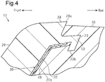
Fig. 4 is a cross-sectional view corresponding toFig. 2 showing a radio-wave transparent cover of another modified embodiment. - Throughout the drawings and the detailed description, the same reference numerals refer to the same elements. The drawings may not be to scale, and the relative size, proportions, and depiction of elements in the drawings may be exaggerated for clarity, illustration, and convenience.
- This description provides a comprehensive understanding of the methods, apparatuses, and/or systems described. Modifications and equivalents of the methods, apparatuses, and/or systems described are apparent to one of ordinary skill in the art. Sequences of operations are exemplary, and may be changed as apparent to one of ordinary skill in the art, with the exception of operations necessarily occurring in a certain order. Descriptions of functions and constructions that are well known to one of ordinary skill in the art may be omitted.
- Exemplary embodiments may have different forms, and are not limited to the examples described. However, the examples described are thorough and complete, and convey the full scope of the disclosure to one of ordinary skill in the art.
- As described above, in the conventional radio-wave transparent cover disclosed in
JP 2009-18790 A - In order to improve aesthetic appearance, it would be desirable to provide the decorative layer closer to the peripheral edge of the radio-wave transparent cover than in the conventional radio-wave transparent cover disclosed in
JP 2009-18790 A - In embodiments, the radio-wave transparent cover includes a transparent layer made of plastic, a decorative layer disposed on a rear-side surface of the transparent layer, and a base layer made of plastic and disposed on a rear-side surface of the decorative layer. The transparent layer has a peripheral part having a protrusion extending rearward. The protrusion defines a peripheral edge of the transparent layer. The protrusion has an inner circumferential surface forming a part of an engaging end projecting rearward from the protrusion. The decorative layer is provided in a region of the rear-side surface of the transparent layer adjoining the inner circumferential surface of the engaging end.
- In embodiments, the decorative layer may extend over the inner circumferential surface of the engaging end and the region of the rear-side surface of the transparent layer adjoining the inner circumferential surface of the engaging end.
- In embodiments, the engaging end may include a distal end portion bent radially outwardly or radially inwardly.
- In embodiments, the protrusion may have a wall thickness in a range of 1.5 to 2.5 mm.
- In embodiments, the engaging end may have a wall thickness in a range of 0.4 to 1.0 mm.
- Hereinafter, an illustrative embodiment of a radio-wave transparent cover will be described with reference to
Figs. 1 and2 . - As shown in
Figs. 1A and 1B , the radio-wave transparent cover (hereinafter, "cover 10") is of an oblong, elliptical shape. Thecover 10 may be, for example, as an emblem. Thecover 10 may be attached to an opening of a front grill of a vehicle. As used herein, the terms "front side" and "rear side" respectively correspond to the front side and the rear side of a vehicle. - The
cover 10 is disposed forward of a radar system mounted to a vehicle and in a path of radio waves (millimeter waves) emitted/received by the radar system. - The
cover 10 has radio-wave transparency and allows millimeter waves to pass through. As shown inFigs. 1B and2 , thecover 10 includes atransparent layer 20, adecorative layer 30 on the rear-side surface of thetransparent layer 20, aprotective layer 40 on the rear-side surface of thedecorative layer 30, and abase layer 50 on the rear-side surface of theprotective layer 40. - The
transparent layer 20 may be made of a polycarbonate, for example. The front-side surface of thetransparent layer 20 is curved rearward near theperipheral edge 20c. - As shown in
Fig. 1B , the rear-side surface of thetransparent layer 20 hasgeneral parts 20a and recessedparts 20b recessed forward from thegeneral parts 20a. The recessedparts 20b may have a depth of about 3.0 mm, for example. - A colored layer (not shown) such as a black layer may be provided by printing on the
general parts 20a. - As shown in
Fig. 2 , thedecorative layer 30 is provided on the entire inner surface of the recessedparts 20b. Thedecorative layer 30 may be made of a metal having radio-wave transparency such as indium. - As shown in
Figs. 1A and 1B , thegeneral parts 20a (colored layers) correspond to background regions 10a of thecover 10, and the recessedparts 20b (decorative layers 30) correspond tophotoluminescent regions 10b of thecover 10. - As shown in
Fig. 2 , aprotrusion 24 extending rearward and defining aperipheral edge 20c of thetransparent layer 20 is provided in aperipheral part 21 on the rear-side surface of thetransparent layer 20. - The
protrusion 24 further has an inner circumferential surface forming a part of anengaging end 23 projecting rearward from theprotrusion 24. Theengaging end 23 is provided circumferentially continuously around thecover 10 and inclines radially outwardly. - The recessed
part 20b located inwardly adjacent theengaging end 23 has aninclined surface 22. Theinclined surface 22 is inclined forward when viewed radially inward. Theinclined surface 22 is adjoining the inner circumferential surface of theengaging end 23. - The
decorative layer 30 extends over the inner circumferential surface of theengaging end 23 and theinclined surface 22. - The
engaging end 23 may have a wall thickness W2 of 0.4 to 1.0 mm. More specifically, theengaging end 23 may have a wall thickness W2 of 0.5 to 0.8 mm. In an illustrative embodiment, theengaging end 23 has a wall thickness W2 of 0.6 mm. - The
protrusion 24 may have a wall thickness W1 of 1.5 to 2.5 mm. More specifically, theprotrusion 24 may have a wall thickness W1 of 1.8 to 2.2 mm. In an illustrative embodiment, theprotrusion 24 has a wall thickness W1 of 2.0 mm. - The
protective layer 40 may be formed from, e.g., a heat-resistant black paint and provided on the entire rear-side surface of thedecorative layer 30. Theprotective layer 40 may have a thickness of several tens of micrometers. Theprotective layer 40 protects thedecorative layer 30 from the heat during insert-molding of thebase layer 50 as will be described further herein. - The
base layer 50 may be formed of a black AES resin. Thebase layer 50 is provided to cover theprotective layer 40 and parts of thetransparent layer 20 not provided with theprotective layer 40. Thebase layer 50 includes an engagingrecess 53 that mates with theengaging end 23 of thetransparent layer 20. - The embodiment described above may provide the following advantages.
- (1) The
cover 10 includes thetransparent layer 20, thedecorative layer 30 disposed on the rear-side surface of thetransparent layer 20, and thebase layer 50 disposed on the rear-side surface of thedecorative layer 30. Thetransparent layer 20 has theperipheral part 21 having theprotrusion 24 extending rearward. Theprotrusion 24 defines theperipheral edge 20c of thetransparent layer 20. Theprotrusion 24 further includes the inner circumferential surface forming a part of theengaging end 23 projecting rearward from theprotrusion 24. Thedecorative layer 30 is provided in a region of the rear-side surface of thetransparent layer 20 adjoining the inner circumferential surface of theengaging end 23. - According to the configuration, the
peripheral part 21 of thetransparent layer 20 has theprotrusion 24 defining theperipheral edge 20c of thetransparent layer 20, and thebase layer 50 is positioned behind theprotrusion 24. Since theprotrusion 24 extends rearward, a portion of the front-side surface of thetransparent layer 20 curved toward theperipheral edge 20c will be entirely reflective. Therefore, thebase layer 50 may not be visible through theprotrusion 24 of thetransparent layer 20. - Further, the
engaging end 23 formed on the rear-side surface of thetransparent layer 20 suppresses contraction of thebase layer 50 as it cools during the molding of thebase layer 50. Thus, wrinkling of thedecorative layer 30 during thermal contraction of thebase layer 50 is prevented. - This way, the aesthetic appearance of the
cover 10 can be improved. - (2) The
decorative layer 30 extends over the inner circumferential surface of theengaging end 23 and a region (the inclined surface 22) of the rear-side surface of thetransparent layer 50 adjoining the inner circumferential surface of theengaging end 23. - According to the configuration, the
decorative layer 30 is provided more closely to theperipheral edge 20c of thetransparent layer 20, so that the aesthetic appearance of thecover 10 can be further improved. As theengaging end 23 inclines radially outwardly, thedecorative layer 30 can be more readily provided closely to theperipheral edge 20c of thetransparent layer 20. - (3) The
protrusion 24 has a wall thickness W1 of 1.5 to 2.5 mm. - The wall thickness W1 of 1.5 mm or more improves the flowability of molten resin toward the outer circumferential side of the
engaging end 23 during the injection molding of thebase layer 50. The wall thickness W1 of 2.5 mm or less allows thedecorative layer 30 to be provided more closely to theperipheral edge 20c of thetransparent layer 20, so that the aesthetic appearance of thecover 10 can be further improved. - (4) The
engaging end 23 has a wall thickness W2 of 0.4 to 1.0 mm. - The wall thickness W2 of 1.0 mm or less improves the flowability of molten resin toward the outer circumferential side of the
engaging end 23 during the injection molding of thebase layer 50. The wall thickness W2 of 0.4 mm or more increases the rigidity of theengaging end 23. - The embodiments described above may be modified as follows. The embodiments and the following modifications can be implemented in combination with each other so long as they do not conflict technically.
- The
transparent layer 20 may be formed from an acrylic resin. In this case, poly(methyl methacrylate) (PMMA), which has good wear resistance, is preferably used. - The wall thickness W2 of the
engaging end 23 may be less than 0.4 mm or more than 1.0 mm. - The wall thickness W1 of the
protrusion 24 may be less than 1.5 mm or more than 2.5 mm. - As shown in
Fig. 3 , theengaging end 23 may further have a distal end portion 23a bent radially outwardly. Alternatively, as shown inFig. 4 , theengaging end 23 may further have adistal end portion 23b bent radially inwardly. These configurations allow thetransparent layer 20 and thebase layer 50 to mate with each other more firmly so that the adhesion between thetransparent layer 20 and thebase layer 50 can be enhanced. This in turn prevents wrinkling of thedecorative layer 30 during thermal contraction of thebase layer 50 more reliably. - It is not necessary that the
decorative layer 30 be provided on the inner circumferential surface of theengaging end 23. - The radio-wave transparent cover of the embodiments is applicable not only as the emblem attached to the opening of a front grill of a vehicle, but also as a cover attached to a part of a vehicle, such as a side part or a rear part. In this case, the front side and the rear side of the cover respectively correspond to the exterior side and the interior side of the vehicle.
- Various changes in form and details may be made to the examples above without departing from the spirit and scope of the claims and their equivalents. The examples are for the sake of description only, and not for purposes of limitation. Descriptions of features in each example are to be considered as being applicable to similar features or aspects in other examples. Suitable results may be achieved if sequences are performed in a different order, and/or if components in a described system, architecture, device, or circuit are combined differently, and/or replaced or supplemented by other components or their equivalents. The scope of the disclosure is not defined by the detailed description, but by the claims and their equivalents. All variations within the scope of the claims and their equivalents are included in the disclosure.
- It is explicitly stated that all features disclosed in the description and/or the claims are intended to be disclosed separately and independently from each other for the purpose of original disclosure as well as for the purpose of restricting the claimed invention independent of the composition of the features in the embodiments and/or the claims. It is explicitly stated that all value ranges or indications of groups of entities disclose every possible intermediate value or intermediate entity for the purpose of original disclosure as well as for the purpose of restricting the claimed invention, in particular as limits of value ranges.
Claims (5)
- A radio-wave transparent cover configured to be disposed in a radio path of a radar system, the radio-wave transparent cover comprising:a plastic transparent layer (20);a decorative layer (30) disposed on a rear-side surface of the transparent layer (20); anda plastic base layer (50) disposed on a rear-side surface of the decorative layer (30), whereinthe transparent layer (20) has a peripheral part (21) having a protrusion (24) extending rearward and defining a peripheral edge (20c) of the transparent layer (20),the protrusion (24) has an inner circumferential surface forming a part of an engaging end (23) projecting rearward from the protrusion (24), andthe decorative layer (30) is provided in a region (22) of the rear-side surface of the transparent layer (20) adjoining the inner circumferential surface of the engaging end (23).
- The radio-wave transparent cover according to claim 1, wherein the decorative layer (30) extends over the inner circumferential surface of the engaging end (23) and the region (22) of the rear-side surface of the transparent layer (20) adjoining the inner circumferential surface of the engaging end (23).
- The radio-wave transparent cover according to claim 1 or 2, wherein the engaging end (23) comprises a distal end portion (23a; 23b) bent radially outwardly or radially inwardly.
- The radio-wave transparent cover according to any one of claims 1 to 3, wherein the protrusion (24) has a wall thickness in a range of 1.5 to 2.5 mm.
- The radio-wave transparent cover according to any one of claims 1 to 4, wherein the engaging end (23) has a wall thickness in a range of 0.4 to 1.0 mm.
Applications Claiming Priority (1)
| Application Number | Priority Date | Filing Date | Title |
|---|---|---|---|
| JP2018065643A JP7077718B2 (en) | 2018-03-29 | 2018-03-29 | Radio wave transmission cover |
Publications (2)
| Publication Number | Publication Date |
|---|---|
| EP3546174A1 true EP3546174A1 (en) | 2019-10-02 |
| EP3546174B1 EP3546174B1 (en) | 2020-11-25 |
Family
ID=65955136
Family Applications (1)
| Application Number | Title | Priority Date | Filing Date |
|---|---|---|---|
| EP19165036.5A Active EP3546174B1 (en) | 2018-03-29 | 2019-03-25 | Radio-wave transparent cover |
Country Status (4)
| Country | Link |
|---|---|
| US (1) | US11152696B2 (en) |
| EP (1) | EP3546174B1 (en) |
| JP (1) | JP7077718B2 (en) |
| CN (1) | CN110316127B (en) |
Families Citing this family (6)
| Publication number | Priority date | Publication date | Assignee | Title |
|---|---|---|---|---|
| KR102282900B1 (en) * | 2019-10-17 | 2021-07-29 | 주식회사 서연이화 | Radio Wave Penetration Cover Manufacturing Method |
| TW202116583A (en) * | 2019-10-24 | 2021-05-01 | 東陽實業廠股份有限公司 | Vehicle trim plateand forming method thereof |
| EP4272958A4 (en) * | 2021-02-05 | 2024-07-10 | Resonac Corporation | Layered structure for automotive emblem and object-sensing structure |
| JP7635730B2 (en) * | 2021-03-26 | 2025-02-26 | 豊田合成株式会社 | Vehicle exterior parts |
| US12487352B2 (en) | 2021-03-26 | 2025-12-02 | Toyota Gosei Co., Ltd. | Vehicle exterior part |
| CN119610718B (en) * | 2024-11-27 | 2025-10-21 | 上海之合玻璃钢有限公司 | Forming method of high-sealing fiberglass reinforced plastic radar antenna cover base |
Citations (7)
| Publication number | Priority date | Publication date | Assignee | Title |
|---|---|---|---|---|
| GB1276842A (en) * | 1968-08-16 | 1972-06-07 | Creators Ltd | Improvements in or relating to decorative trim strips |
| JP2009018790A (en) | 2007-06-13 | 2009-01-29 | Toyoda Gosei Co Ltd | Radio wave transmission cover and manufacturing method of the cover |
| JP2010105253A (en) * | 2008-10-29 | 2010-05-13 | Nissha Printing Co Ltd | Injection molding mold and method for producing resin molding using the mold |
| KR101369078B1 (en) * | 2013-05-16 | 2014-02-28 | 최성 | Method of manufacturing an emblem and emblem |
| JP2016141355A (en) * | 2015-02-05 | 2016-08-08 | 豊田合成株式会社 | Radio wave transmission cover for vehicle |
| WO2018025687A1 (en) * | 2016-08-01 | 2018-02-08 | サカエ理研工業株式会社 | Radio wave-transmissive cover |
| WO2018061250A1 (en) * | 2016-09-29 | 2018-04-05 | マツダ株式会社 | Method and device for insert-molding film material |
Family Cites Families (26)
| Publication number | Priority date | Publication date | Assignee | Title |
|---|---|---|---|---|
| US6750819B2 (en) * | 2002-01-10 | 2004-06-15 | Visteon Global Technologies, Inc. | Sensor cover and method of construction thereof |
| JP4022819B2 (en) * | 2002-12-26 | 2007-12-19 | 豊田合成株式会社 | Radio wave transmission cover |
| JP2005050697A (en) * | 2003-07-29 | 2005-02-24 | Toyota Industries Corp | Organic electroluminescence device |
| JP2006264593A (en) * | 2005-03-25 | 2006-10-05 | Toyota Motor Corp | Brightening molded parts for radar device beam path |
| JP4771118B2 (en) * | 2005-06-20 | 2011-09-14 | 豊田合成株式会社 | Manufacturing method of resin laminated member |
| JP2007142780A (en) * | 2005-11-17 | 2007-06-07 | Toyoda Gosei Co Ltd | Decorative component for vehicle |
| EP1972504B8 (en) * | 2007-03-22 | 2018-03-21 | Toyoda Gosei Co., Ltd. | Radio wave transmission cover and method of manufacturing the same |
| US7990334B2 (en) * | 2007-06-13 | 2011-08-02 | Toyoda Gosei Co., Ltd. | Radio wave transmission cover and method of manufacturing radio wave transmission cover |
| JP4720866B2 (en) * | 2008-07-30 | 2011-07-13 | 豊田合成株式会社 | Decorative member and manufacturing method thereof |
| IT1396079B1 (en) * | 2009-10-16 | 2012-11-09 | Zanini Holding S P A | PROCESS OF MANUFACTURE OF A DECORATIVE ELEMENT, PARTICULARLY INTENDED FOR USE AS AN EMBLEM ON A MOTOR VEHICLE. |
| US9114760B2 (en) * | 2010-11-15 | 2015-08-25 | Zanini Auto Grup, Sa | Decorative radome for automotive vehicular applications |
| JP2014069634A (en) * | 2012-09-28 | 2014-04-21 | Toyoda Gosei Co Ltd | Vehicle decorative member |
| WO2014149201A1 (en) * | 2013-03-15 | 2014-09-25 | Agc Automotive Americas R& D, Inc. | Window assembly with transparent regions having a perfoormance enhancing slit formed therein |
| JP6108173B2 (en) * | 2013-09-26 | 2017-04-05 | 豊田合成株式会社 | Decorative materials for vehicles |
| JP2016080479A (en) * | 2014-10-15 | 2016-05-16 | 豊田合成株式会社 | Radio wave transmissive cover |
| JP6216708B2 (en) | 2014-12-26 | 2017-10-18 | 株式会社ファルテック | Radar cover manufacturing method and radar cover |
| JP6467985B2 (en) * | 2015-02-25 | 2019-02-13 | 豊田合成株式会社 | Manufacturing method of electromagnetic wave transmission cover |
| JP6552326B2 (en) * | 2015-08-07 | 2019-07-31 | 株式会社東海理化電機製作所 | Radio wave transmission parts |
| US10651530B2 (en) * | 2016-06-01 | 2020-05-12 | Toyoda Gosei Co., Ltd. | Decorative component for vehicle |
| US10974661B2 (en) * | 2016-10-21 | 2021-04-13 | Toyoda Gosei Co., Ltd. | Decorative part for vehicle and method for manufacturing same |
| US20180159207A1 (en) * | 2016-12-02 | 2018-06-07 | Srg Global Inc. | Multi-piece vehicle radome having non-uniform back piece |
| EP3552884A4 (en) * | 2016-12-09 | 2020-07-29 | Faltec Co., Ltd. | RADAR COVER AND PRODUCTION METHOD FOR A RADAR COVER |
| KR102463471B1 (en) * | 2016-12-14 | 2022-11-08 | 현대자동차주식회사 | Method for manufacturing of scc cover for vehicle and the same |
| JP6784240B2 (en) * | 2017-07-26 | 2020-11-11 | 豊田合成株式会社 | Radio wave transmission cover |
| JP6874670B2 (en) * | 2017-12-18 | 2021-05-19 | 豊田合成株式会社 | Radio wave transmission cover |
| JP2019179969A (en) * | 2018-03-30 | 2019-10-17 | 豊田合成株式会社 | Radio wave transmission cover and method of manufacturing the same |
-
2018
- 2018-03-29 JP JP2018065643A patent/JP7077718B2/en active Active
-
2019
- 2019-03-15 US US16/354,777 patent/US11152696B2/en active Active
- 2019-03-25 EP EP19165036.5A patent/EP3546174B1/en active Active
- 2019-03-27 CN CN201910237508.6A patent/CN110316127B/en active Active
Patent Citations (7)
| Publication number | Priority date | Publication date | Assignee | Title |
|---|---|---|---|---|
| GB1276842A (en) * | 1968-08-16 | 1972-06-07 | Creators Ltd | Improvements in or relating to decorative trim strips |
| JP2009018790A (en) | 2007-06-13 | 2009-01-29 | Toyoda Gosei Co Ltd | Radio wave transmission cover and manufacturing method of the cover |
| JP2010105253A (en) * | 2008-10-29 | 2010-05-13 | Nissha Printing Co Ltd | Injection molding mold and method for producing resin molding using the mold |
| KR101369078B1 (en) * | 2013-05-16 | 2014-02-28 | 최성 | Method of manufacturing an emblem and emblem |
| JP2016141355A (en) * | 2015-02-05 | 2016-08-08 | 豊田合成株式会社 | Radio wave transmission cover for vehicle |
| WO2018025687A1 (en) * | 2016-08-01 | 2018-02-08 | サカエ理研工業株式会社 | Radio wave-transmissive cover |
| WO2018061250A1 (en) * | 2016-09-29 | 2018-04-05 | マツダ株式会社 | Method and device for insert-molding film material |
Also Published As
| Publication number | Publication date |
|---|---|
| JP7077718B2 (en) | 2022-05-31 |
| CN110316127B (en) | 2023-05-23 |
| US11152696B2 (en) | 2021-10-19 |
| US20190305412A1 (en) | 2019-10-03 |
| EP3546174B1 (en) | 2020-11-25 |
| JP2019171804A (en) | 2019-10-10 |
| CN110316127A (en) | 2019-10-11 |
Similar Documents
| Publication | Publication Date | Title |
|---|---|---|
| EP3546174B1 (en) | Radio-wave transparent cover | |
| EP3248751B1 (en) | Method for manufacturing radar cover and radar cover | |
| US8974712B2 (en) | Method of manufacturing radome | |
| EP3300169B1 (en) | Radar cover and method of manufacturing the radar cover | |
| JP5460218B2 (en) | Manufacturing method of radome | |
| JP4848985B2 (en) | Radio wave transmission cover | |
| JP2016182866A (en) | Vehicle attachment part | |
| CN107949794B (en) | Method for manufacturing radome, and radome | |
| EP3933431A1 (en) | Radar cover | |
| JP6343594B2 (en) | Radar cover manufacturing method and radar cover | |
| JP2008024254A (en) | Vehicle exterior parts and method for manufacturing the same | |
| JP2019128255A (en) | Radar cover, and radar cover manufacturing method | |
| JP6868549B2 (en) | Radar cover | |
| JP2018159585A (en) | Radar cover and radar cover manufacturing method | |
| JP2020147204A (en) | Manufacturing method of vehicle cover member and vehicle cover member | |
| JP2021037836A (en) | Radar cover | |
| JP6954962B2 (en) | Radar cover and radar cover manufacturing method | |
| JP2017178015A (en) | Transparent member, radar cover, and manufacturing method of radar cover | |
| JP2021121514A (en) | Radar cover and manufacturing method of radar cover |
Legal Events
| Date | Code | Title | Description |
|---|---|---|---|
| PUAI | Public reference made under article 153(3) epc to a published international application that has entered the european phase |
Free format text: ORIGINAL CODE: 0009012 |
|
| STAA | Information on the status of an ep patent application or granted ep patent |
Free format text: STATUS: THE APPLICATION HAS BEEN PUBLISHED |
|
| AK | Designated contracting states |
Kind code of ref document: A1 Designated state(s): AL AT BE BG CH CY CZ DE DK EE ES FI FR GB GR HR HU IE IS IT LI LT LU LV MC MK MT NL NO PL PT RO RS SE SI SK SM TR |
|
| AX | Request for extension of the european patent |
Extension state: BA ME |
|
| STAA | Information on the status of an ep patent application or granted ep patent |
Free format text: STATUS: REQUEST FOR EXAMINATION WAS MADE |
|
| 17P | Request for examination filed |
Effective date: 20191121 |
|
| RBV | Designated contracting states (corrected) |
Designated state(s): AL AT BE BG CH CY CZ DE DK EE ES FI FR GB GR HR HU IE IS IT LI LT LU LV MC MK MT NL NO PL PT RO RS SE SI SK SM TR |
|
| GRAP | Despatch of communication of intention to grant a patent |
Free format text: ORIGINAL CODE: EPIDOSNIGR1 |
|
| STAA | Information on the status of an ep patent application or granted ep patent |
Free format text: STATUS: GRANT OF PATENT IS INTENDED |
|
| GRAJ | Information related to disapproval of communication of intention to grant by the applicant or resumption of examination proceedings by the epo deleted |
Free format text: ORIGINAL CODE: EPIDOSDIGR1 |
|
| STAA | Information on the status of an ep patent application or granted ep patent |
Free format text: STATUS: REQUEST FOR EXAMINATION WAS MADE |
|
| INTG | Intention to grant announced |
Effective date: 20200430 |
|
| RIC1 | Information provided on ipc code assigned before grant |
Ipc: B29L 31/34 20060101ALN20200417BHEP Ipc: H01Q 1/32 20060101ALI20200417BHEP Ipc: B29C 45/14 20060101ALI20200417BHEP Ipc: B29C 45/16 20060101AFI20200417BHEP Ipc: H01Q 1/44 20060101ALI20200417BHEP Ipc: H01Q 1/42 20060101ALN20200417BHEP |
|
| INTC | Intention to grant announced (deleted) | ||
| GRAP | Despatch of communication of intention to grant a patent |
Free format text: ORIGINAL CODE: EPIDOSNIGR1 |
|
| STAA | Information on the status of an ep patent application or granted ep patent |
Free format text: STATUS: GRANT OF PATENT IS INTENDED |
|
| INTG | Intention to grant announced |
Effective date: 20200618 |
|
| RIC1 | Information provided on ipc code assigned before grant |
Ipc: H01Q 1/32 20060101ALI20200608BHEP Ipc: H01Q 1/42 20060101ALN20200608BHEP Ipc: B29C 45/16 20060101AFI20200608BHEP Ipc: B29C 45/14 20060101ALI20200608BHEP Ipc: B29L 31/34 20060101ALN20200608BHEP Ipc: H01Q 1/44 20060101ALI20200608BHEP |
|
| INTG | Intention to grant announced |
Effective date: 20200624 |
|
| RIC1 | Information provided on ipc code assigned before grant |
Ipc: H01Q 1/32 20060101ALI20200616BHEP Ipc: B29C 45/16 20060101AFI20200616BHEP Ipc: H01Q 1/44 20060101ALI20200616BHEP Ipc: H01Q 1/42 20060101ALN20200616BHEP Ipc: B29L 31/34 20060101ALN20200616BHEP Ipc: B29C 45/14 20060101ALI20200616BHEP |
|
| GRAS | Grant fee paid |
Free format text: ORIGINAL CODE: EPIDOSNIGR3 |
|
| GRAA | (expected) grant |
Free format text: ORIGINAL CODE: 0009210 |
|
| STAA | Information on the status of an ep patent application or granted ep patent |
Free format text: STATUS: THE PATENT HAS BEEN GRANTED |
|
| AK | Designated contracting states |
Kind code of ref document: B1 Designated state(s): AL AT BE BG CH CY CZ DE DK EE ES FI FR GB GR HR HU IE IS IT LI LT LU LV MC MK MT NL NO PL PT RO RS SE SI SK SM TR |
|
| REG | Reference to a national code |
Ref country code: GB Ref legal event code: FG4D |
|
| REG | Reference to a national code |
Ref country code: CH Ref legal event code: EP |
|
| REG | Reference to a national code |
Ref country code: AT Ref legal event code: REF Ref document number: 1337775 Country of ref document: AT Kind code of ref document: T Effective date: 20201215 |
|
| REG | Reference to a national code |
Ref country code: DE Ref legal event code: R096 Ref document number: 602019001441 Country of ref document: DE |
|
| REG | Reference to a national code |
Ref country code: IE Ref legal event code: FG4D |
|
| REG | Reference to a national code |
Ref country code: AT Ref legal event code: MK05 Ref document number: 1337775 Country of ref document: AT Kind code of ref document: T Effective date: 20201125 |
|
| REG | Reference to a national code |
Ref country code: NL Ref legal event code: MP Effective date: 20201125 |
|
| PG25 | Lapsed in a contracting state [announced via postgrant information from national office to epo] |
Ref country code: GR Free format text: LAPSE BECAUSE OF FAILURE TO SUBMIT A TRANSLATION OF THE DESCRIPTION OR TO PAY THE FEE WITHIN THE PRESCRIBED TIME-LIMIT Effective date: 20210226 Ref country code: NO Free format text: LAPSE BECAUSE OF FAILURE TO SUBMIT A TRANSLATION OF THE DESCRIPTION OR TO PAY THE FEE WITHIN THE PRESCRIBED TIME-LIMIT Effective date: 20210225 Ref country code: FI Free format text: LAPSE BECAUSE OF FAILURE TO SUBMIT A TRANSLATION OF THE DESCRIPTION OR TO PAY THE FEE WITHIN THE PRESCRIBED TIME-LIMIT Effective date: 20201125 Ref country code: RS Free format text: LAPSE BECAUSE OF FAILURE TO SUBMIT A TRANSLATION OF THE DESCRIPTION OR TO PAY THE FEE WITHIN THE PRESCRIBED TIME-LIMIT Effective date: 20201125 Ref country code: PT Free format text: LAPSE BECAUSE OF FAILURE TO SUBMIT A TRANSLATION OF THE DESCRIPTION OR TO PAY THE FEE WITHIN THE PRESCRIBED TIME-LIMIT Effective date: 20210325 |
|
| PG25 | Lapsed in a contracting state [announced via postgrant information from national office to epo] |
Ref country code: BG Free format text: LAPSE BECAUSE OF FAILURE TO SUBMIT A TRANSLATION OF THE DESCRIPTION OR TO PAY THE FEE WITHIN THE PRESCRIBED TIME-LIMIT Effective date: 20210225 Ref country code: SE Free format text: LAPSE BECAUSE OF FAILURE TO SUBMIT A TRANSLATION OF THE DESCRIPTION OR TO PAY THE FEE WITHIN THE PRESCRIBED TIME-LIMIT Effective date: 20201125 Ref country code: IS Free format text: LAPSE BECAUSE OF FAILURE TO SUBMIT A TRANSLATION OF THE DESCRIPTION OR TO PAY THE FEE WITHIN THE PRESCRIBED TIME-LIMIT Effective date: 20210325 Ref country code: PL Free format text: LAPSE BECAUSE OF FAILURE TO SUBMIT A TRANSLATION OF THE DESCRIPTION OR TO PAY THE FEE WITHIN THE PRESCRIBED TIME-LIMIT Effective date: 20201125 Ref country code: LV Free format text: LAPSE BECAUSE OF FAILURE TO SUBMIT A TRANSLATION OF THE DESCRIPTION OR TO PAY THE FEE WITHIN THE PRESCRIBED TIME-LIMIT Effective date: 20201125 Ref country code: AT Free format text: LAPSE BECAUSE OF FAILURE TO SUBMIT A TRANSLATION OF THE DESCRIPTION OR TO PAY THE FEE WITHIN THE PRESCRIBED TIME-LIMIT Effective date: 20201125 |
|
| REG | Reference to a national code |
Ref country code: LT Ref legal event code: MG9D |
|
| PG25 | Lapsed in a contracting state [announced via postgrant information from national office to epo] |
Ref country code: HR Free format text: LAPSE BECAUSE OF FAILURE TO SUBMIT A TRANSLATION OF THE DESCRIPTION OR TO PAY THE FEE WITHIN THE PRESCRIBED TIME-LIMIT Effective date: 20201125 |
|
| PG25 | Lapsed in a contracting state [announced via postgrant information from national office to epo] |
Ref country code: CZ Free format text: LAPSE BECAUSE OF FAILURE TO SUBMIT A TRANSLATION OF THE DESCRIPTION OR TO PAY THE FEE WITHIN THE PRESCRIBED TIME-LIMIT Effective date: 20201125 Ref country code: SM Free format text: LAPSE BECAUSE OF FAILURE TO SUBMIT A TRANSLATION OF THE DESCRIPTION OR TO PAY THE FEE WITHIN THE PRESCRIBED TIME-LIMIT Effective date: 20201125 Ref country code: SK Free format text: LAPSE BECAUSE OF FAILURE TO SUBMIT A TRANSLATION OF THE DESCRIPTION OR TO PAY THE FEE WITHIN THE PRESCRIBED TIME-LIMIT Effective date: 20201125 Ref country code: EE Free format text: LAPSE BECAUSE OF FAILURE TO SUBMIT A TRANSLATION OF THE DESCRIPTION OR TO PAY THE FEE WITHIN THE PRESCRIBED TIME-LIMIT Effective date: 20201125 Ref country code: RO Free format text: LAPSE BECAUSE OF FAILURE TO SUBMIT A TRANSLATION OF THE DESCRIPTION OR TO PAY THE FEE WITHIN THE PRESCRIBED TIME-LIMIT Effective date: 20201125 Ref country code: LT Free format text: LAPSE BECAUSE OF FAILURE TO SUBMIT A TRANSLATION OF THE DESCRIPTION OR TO PAY THE FEE WITHIN THE PRESCRIBED TIME-LIMIT Effective date: 20201125 |
|
| REG | Reference to a national code |
Ref country code: DE Ref legal event code: R097 Ref document number: 602019001441 Country of ref document: DE |
|
| PG25 | Lapsed in a contracting state [announced via postgrant information from national office to epo] |
Ref country code: DK Free format text: LAPSE BECAUSE OF FAILURE TO SUBMIT A TRANSLATION OF THE DESCRIPTION OR TO PAY THE FEE WITHIN THE PRESCRIBED TIME-LIMIT Effective date: 20201125 |
|
| PLBE | No opposition filed within time limit |
Free format text: ORIGINAL CODE: 0009261 |
|
| STAA | Information on the status of an ep patent application or granted ep patent |
Free format text: STATUS: NO OPPOSITION FILED WITHIN TIME LIMIT |
|
| PG25 | Lapsed in a contracting state [announced via postgrant information from national office to epo] |
Ref country code: AL Free format text: LAPSE BECAUSE OF FAILURE TO SUBMIT A TRANSLATION OF THE DESCRIPTION OR TO PAY THE FEE WITHIN THE PRESCRIBED TIME-LIMIT Effective date: 20201125 Ref country code: NL Free format text: LAPSE BECAUSE OF FAILURE TO SUBMIT A TRANSLATION OF THE DESCRIPTION OR TO PAY THE FEE WITHIN THE PRESCRIBED TIME-LIMIT Effective date: 20201125 Ref country code: IT Free format text: LAPSE BECAUSE OF FAILURE TO SUBMIT A TRANSLATION OF THE DESCRIPTION OR TO PAY THE FEE WITHIN THE PRESCRIBED TIME-LIMIT Effective date: 20201125 Ref country code: MC Free format text: LAPSE BECAUSE OF FAILURE TO SUBMIT A TRANSLATION OF THE DESCRIPTION OR TO PAY THE FEE WITHIN THE PRESCRIBED TIME-LIMIT Effective date: 20201125 |
|
| 26N | No opposition filed |
Effective date: 20210826 |
|
| PG25 | Lapsed in a contracting state [announced via postgrant information from national office to epo] |
Ref country code: SI Free format text: LAPSE BECAUSE OF FAILURE TO SUBMIT A TRANSLATION OF THE DESCRIPTION OR TO PAY THE FEE WITHIN THE PRESCRIBED TIME-LIMIT Effective date: 20201125 |
|
| REG | Reference to a national code |
Ref country code: BE Ref legal event code: MM Effective date: 20210331 |
|
| PG25 | Lapsed in a contracting state [announced via postgrant information from national office to epo] |
Ref country code: ES Free format text: LAPSE BECAUSE OF FAILURE TO SUBMIT A TRANSLATION OF THE DESCRIPTION OR TO PAY THE FEE WITHIN THE PRESCRIBED TIME-LIMIT Effective date: 20201125 Ref country code: FR Free format text: LAPSE BECAUSE OF NON-PAYMENT OF DUE FEES Effective date: 20210331 Ref country code: LU Free format text: LAPSE BECAUSE OF NON-PAYMENT OF DUE FEES Effective date: 20210325 Ref country code: IE Free format text: LAPSE BECAUSE OF NON-PAYMENT OF DUE FEES Effective date: 20210325 |
|
| PG25 | Lapsed in a contracting state [announced via postgrant information from national office to epo] |
Ref country code: IS Free format text: LAPSE BECAUSE OF FAILURE TO SUBMIT A TRANSLATION OF THE DESCRIPTION OR TO PAY THE FEE WITHIN THE PRESCRIBED TIME-LIMIT Effective date: 20210325 |
|
| PG25 | Lapsed in a contracting state [announced via postgrant information from national office to epo] |
Ref country code: BE Free format text: LAPSE BECAUSE OF NON-PAYMENT OF DUE FEES Effective date: 20210331 |
|
| REG | Reference to a national code |
Ref country code: CH Ref legal event code: PL |
|
| PG25 | Lapsed in a contracting state [announced via postgrant information from national office to epo] |
Ref country code: LI Free format text: LAPSE BECAUSE OF NON-PAYMENT OF DUE FEES Effective date: 20220331 Ref country code: CH Free format text: LAPSE BECAUSE OF NON-PAYMENT OF DUE FEES Effective date: 20220331 |
|
| PG25 | Lapsed in a contracting state [announced via postgrant information from national office to epo] |
Ref country code: CY Free format text: LAPSE BECAUSE OF FAILURE TO SUBMIT A TRANSLATION OF THE DESCRIPTION OR TO PAY THE FEE WITHIN THE PRESCRIBED TIME-LIMIT Effective date: 20201125 |
|
| PG25 | Lapsed in a contracting state [announced via postgrant information from national office to epo] |
Ref country code: HU Free format text: LAPSE BECAUSE OF FAILURE TO SUBMIT A TRANSLATION OF THE DESCRIPTION OR TO PAY THE FEE WITHIN THE PRESCRIBED TIME-LIMIT; INVALID AB INITIO Effective date: 20190325 |
|
| GBPC | Gb: european patent ceased through non-payment of renewal fee |
Effective date: 20230325 |
|
| PG25 | Lapsed in a contracting state [announced via postgrant information from national office to epo] |
Ref country code: GB Free format text: LAPSE BECAUSE OF NON-PAYMENT OF DUE FEES Effective date: 20230325 |
|
| PG25 | Lapsed in a contracting state [announced via postgrant information from national office to epo] |
Ref country code: GB Free format text: LAPSE BECAUSE OF NON-PAYMENT OF DUE FEES Effective date: 20230325 |
|
| PG25 | Lapsed in a contracting state [announced via postgrant information from national office to epo] |
Ref country code: MK Free format text: LAPSE BECAUSE OF FAILURE TO SUBMIT A TRANSLATION OF THE DESCRIPTION OR TO PAY THE FEE WITHIN THE PRESCRIBED TIME-LIMIT Effective date: 20201125 |
|
| PG25 | Lapsed in a contracting state [announced via postgrant information from national office to epo] |
Ref country code: TR Free format text: LAPSE BECAUSE OF FAILURE TO SUBMIT A TRANSLATION OF THE DESCRIPTION OR TO PAY THE FEE WITHIN THE PRESCRIBED TIME-LIMIT Effective date: 20201125 |
|
| PG25 | Lapsed in a contracting state [announced via postgrant information from national office to epo] |
Ref country code: MT Free format text: LAPSE BECAUSE OF FAILURE TO SUBMIT A TRANSLATION OF THE DESCRIPTION OR TO PAY THE FEE WITHIN THE PRESCRIBED TIME-LIMIT Effective date: 20201125 |
|
| PGFP | Annual fee paid to national office [announced via postgrant information from national office to epo] |
Ref country code: DE Payment date: 20260128 Year of fee payment: 8 |