EP3546130A1 - Tool with charge advance mechanism - Google Patents
Tool with charge advance mechanism Download PDFInfo
- Publication number
- EP3546130A1 EP3546130A1 EP18202353.1A EP18202353A EP3546130A1 EP 3546130 A1 EP3546130 A1 EP 3546130A1 EP 18202353 A EP18202353 A EP 18202353A EP 3546130 A1 EP3546130 A1 EP 3546130A1
- Authority
- EP
- European Patent Office
- Prior art keywords
- ratchet
- charge
- barrel
- powder
- tool
- Prior art date
- Legal status (The legal status is an assumption and is not a legal conclusion. Google has not performed a legal analysis and makes no representation as to the accuracy of the status listed.)
- Granted
Links
Images






Classifications
-
- B—PERFORMING OPERATIONS; TRANSPORTING
- B25—HAND TOOLS; PORTABLE POWER-DRIVEN TOOLS; MANIPULATORS
- B25C—HAND-HELD NAILING OR STAPLING TOOLS; MANUALLY OPERATED PORTABLE STAPLING TOOLS
- B25C1/00—Hand-held nailing tools; Nail feeding devices
- B25C1/08—Hand-held nailing tools; Nail feeding devices operated by combustion pressure
- B25C1/10—Hand-held nailing tools; Nail feeding devices operated by combustion pressure generated by detonation of a cartridge
- B25C1/18—Details and accessories, e.g. splinter guards, spall minimisers
- B25C1/182—Feeding devices
- B25C1/186—Feeding devices for cartridges or pellets
-
- B—PERFORMING OPERATIONS; TRANSPORTING
- B25—HAND TOOLS; PORTABLE POWER-DRIVEN TOOLS; MANIPULATORS
- B25C—HAND-HELD NAILING OR STAPLING TOOLS; MANUALLY OPERATED PORTABLE STAPLING TOOLS
- B25C1/00—Hand-held nailing tools; Nail feeding devices
- B25C1/08—Hand-held nailing tools; Nail feeding devices operated by combustion pressure
- B25C1/082—Hand-held nailing tools; Nail feeding devices operated by combustion pressure generated by detonation of a pellet
- B25C1/085—Hand-held nailing tools; Nail feeding devices operated by combustion pressure generated by detonation of a pellet trigger operated
-
- B—PERFORMING OPERATIONS; TRANSPORTING
- B25—HAND TOOLS; PORTABLE POWER-DRIVEN TOOLS; MANIPULATORS
- B25C—HAND-HELD NAILING OR STAPLING TOOLS; MANUALLY OPERATED PORTABLE STAPLING TOOLS
- B25C7/00—Accessories for nailing or stapling tools, e.g. supports
Definitions
- the barrel 16 has mounted thereon an alignment member 28 (shown in the form of a lockout pin) which moves relative to the rotatable ratchet 18 when the barrel 16 is brought from the open position (see Figure 7 ) to the closed position (see Figure 8 ) to ensure a charge 30 of the powder charge strip 14 is in alignment with the barrel 16.
- the alignment member 28 is moved into abutment with the ratchet 18 to prevent the ratchet 18 from rotating, thereby preventing the charge 30 from moving out of alignment with the barrel 16.
- the lockout pin 28 disengages with the ratchet wheel 18 along with the barrel breech disengaging from the charge.
- the charge advance lever 24 pulls on the vertical face of the ratchet wheel's ramp 40a causing the ratchet wheel 18 to rotate (see Figure 10 and Figure 11 ).
- Pins/teeth 20 on the ratchet wheel 18 engage with mating slots/receptacles in the charge strip 14, acting as rack and pinion gearing.
- the charge strip 14 is pulled through the breech by the pins/teeth 20. The engagement of the pins/teeth with the slots/receptacles in the charge strip 14 is shown in Figure 26 .
Landscapes
- Engineering & Computer Science (AREA)
- Mechanical Engineering (AREA)
- Chemical & Material Sciences (AREA)
- Combustion & Propulsion (AREA)
- Portable Nailing Machines And Staplers (AREA)
- Mechanical Pencils And Projecting And Retracting Systems Therefor, And Multi-System Writing Instruments (AREA)
- Details Of Spanners, Wrenches, And Screw Drivers And Accessories (AREA)
- Powder Metallurgy (AREA)
Abstract
Description
- The present invention relates generally to a tool with a charge advance mechanism and, more specifically but not exclusively, to a powder actuated fastening tool having a charge advance mechanism for advancing a strip of powder charges relative to the tool.
- It is has been previously proposed to provide a powder actuated fastening tool which operates on a strip of explosive powder charges to drive fasteners into a workpiece. It is necessary for the powder charge strip to be driven progressively through the tool such that the strip is moved through the tool so that successive charges are used for firing successive fasteners through a barrel of the tool. In this way, it is desirable that each of the powder charges in the strip is progressively depleted to drive the fasteners from the fastening tool.
- However, the applicant has identified that there is a problem with existing powder actuated fastening tools in that the powder charge strip may not be accurately or adequately moved through the tool such that a charge may be out of alignment with the barrel, raising the problem of potentially having charges damaged by the tool or even activated outside of the barrel of the tool, which may be potentially dangerous or at least destructive to the tool.
- Examples of the present invention seek to provide an improved tool with charge advance mechanism which may avoid or at least ameliorate disadvantages of existing powder actuated tools.
- In accordance with one aspect of the present invention, there is provided a powder actuated fastening tool including a charge advance apparatus for advancing a powder charge strip relative to a barrel of the tool, wherein the charge advance apparatus includes a rotatable ratchet having teeth for engaging receptacles formed in the powder charge strip, and a charge advance member coupled to a trigger of the tool, wherein the charge advance member acts on the rotatable ratchet to rotate the ratchet in response to actuation and/or release of the trigger, such that the rotation of the ratchet causes advance of the powder charge strip relative to the barrel.
- Preferably, the barrel has mounted thereon an alignment member which moves relative to the ratchet when the barrel is brought from the open position to the closed position to ensure a charge of the powder charge strip is in alignment with the barrel.
- More preferably, when the barrel is brought from the open position to the closed position, the alignment member is moved into abutment with the ratchet to prevent the ratchet from rotating, thereby preventing the charge from moving out of alignment with the barrel.
- Even more preferably, the rotatable ratchet has a plurality of straight sides, such that when the barrel is brought from the open position to the closed position, the alignment member is moved into abutment with one of the straight sides to prevent rotation of the ratchet.
- Even more preferably, the alignment member is moved into abutment with said straight side in a direction parallel to the straight side. In one form, the alignment member is in the form of an elongated rod.
- Preferably, the rotatable ratchet is hexagonal.
- Preferably, the rotatable ratchet is arranged to pivots about a central axis of the rotatable ratchet. In one form, the central axis is perpendicular to a longitudinal axis of the elongated rod. More preferably, the rotatable ratchet is provided with a series of ratchet ramps equally spaced in a circular arrangement around the central axis. Even more preferably, the ratchet ramps are arranged such that one ratchet ramp coincides to one charge of the charge strip, with rotation of the ratchet by one ratchet ramp corresponding with movement of the strip by one powder charge.
- Preferably, the rotatable ratchet is mounted to permit tilting of the ratchet, with a central spring biasing the ratchet to an untilted configuration.
- Preferably, each of the teeth has an involute profile to facilitate meshing with the strip.
- In a preferred form, the charge advance member is in the form of an arm. More preferably, the arm is fixed to the trigger to move with the trigger as the trigger is pulled by the user. Even more preferably, the arm is arranged to deflect laterally over one ratchet ramp on pulling of the trigger. In one form, the arm has a catch for engaging with said ratchet ramp to drive rotation of the ratchet on return of the trigger.
- In accordance with another aspect of the present invention, there is provided a powder actuated fastening tool including a charge advance apparatus for advancing a powder charge strip relative to a barrel of the tool, wherein the charge advance apparatus includes a rotatable ratchet having teeth for engaging receptacles formed in the powder charge strip, wherein the barrel is slideably mounted between an open position in which the barrel is spaced from the charge and a closed position in which the barrel encloses the charge, wherein the barrel has mounted thereon an alignment member which moves relative to the ratchet when the barrel is brought from the open position to the closed position to ensure a charge is in alignment with the barrel.
- Preferably, the tool includes a charge advance member coupled to a trigger of the tool, wherein the charge advance member acts upon the rotatable ratchet to rotate the ratchet in response to actuation and/or release of the trigger, such that the rotation of the ratchet causes advance of the powder charge strip.
- The invention is described, by way of non-limiting example only, with reference to the accompanying drawings, in which:
-
Figure 1 shows a perspective view of a partially dismantled tool having a charge advance mechanism in accordance with an example of the present invention; -
Figure 2 shows a perspective view of the charge advance mechanism; -
Figure 3 shows a perspective view of a rotatable ratchet of the charge advance mechanism; -
Figure 4 shows a top view of the ratchet; -
Figure 5 shows a side view of the ratchet; -
Figure 6 shows a bottom view of the ratchet; -
Figure 7 shows a perspective view of the charge advance mechanism with the barrel in an open position; -
Figure 8 shows a perspective view of the charge advance mechanism with the barrel in a closed position; -
Figure 9 shows a perspective view of the charge advance mechanism with the barrel in the closed position and the trigger pulled back; -
Figure 10 shows a perspective view of the charge advance mechanism with the barrel in the open position and the trigger driving rotation of the ratchet; -
Figure 11 shows a perspective view of the charge advance mechanism with the barrel in the open position and the trigger returned to the rest position; -
Figure 12 shows an underside view of a charge advance member coupled to the trigger in a first stage of a deployment cycle of the tool; -
Figure 13 shows the charge advance member relative to the ratchet in a second stage of the deployment cycle; -
Figure 14 shows a third stage of the deployment cycle; -
Figure 15 shows a fourth stage of the deployment cycle; -
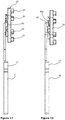
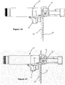
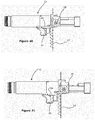
Figures 16 to 21 show a side view of the tool in successive steps over a single deployment cycle of the tool, including movement of the barrel, trigger and charge strip; -
Figures 22 to 26 show successive steps in initial loading of the strip into the tool and, in particular, engagement of teeth of the ratchet with the strip; -
Figure 27 shows detail of the barrel and ratchet with the barrel in the open position; -
Figure 28 shows a rear perspective view of the ratchet and barrel, with the barrel in the closed position; and -
Figure 29 shows a front perspective view of the ratchet and barrel, with the barrel in the closed position. - With reference to
Figures 1 to 29 of the drawings, there is shown a powder actuatedfastening tool 10 having acharge advance apparatus 12 which, advantageously, ensures that a strip of powder charges is accurately and adequately advanced through thetool 10 such that the charges are properly aligned with a barrel of thetool 10 for safe and effective operation of the tool. - More specifically, with reference to
Figures 1 and 2 of the drawings, thecharge advance apparatus 12 is for advancing apowder charge strip 14 relative to abarrel 16 of thetool 10. Thecharge advance apparatus 12 includes arotatable ratchet 18 havingteeth 20 forengaging receptacles 22 formed in thepowder charge strip 14. In the example shown, thecharge advance apparatus 12 also includes acharge advance member 24, in the form of a charge advance lever, coupled to atrigger 26 of thetool 10. Thecharge advance member 24 acts on therotatable ratchet 18 to rotate the ratchet 18 (shown inFigure 2 in the form of a ratchet wheel) in response to actuation and/or release of thetrigger 26, such that the rotation of theratchet 18 causes advance of thepowder charge strip 14 relative to the section ofbarrel 16 shown inFigure 2 . InFigure 1 , thetool 10 is shown in an assembled form without a left hand side housing. As shown inFigure 2 , acantilever spring 25 may be provided for biasing a distal end of thecharge advance member 24 toward therotatable ratchet 18. - Detail of the
rotatable ratchet 18 is shown inFigures 3 to 6 of the drawings. With reference toFigure 3 , an inner bore of therotatable ratchet 18 wheel is tapered, having atapered base 39, allowing the wheel to pivot, allowing the wheel's pins to lift out of the way upon insertion of thecharge strip 14.Figure 4 shows therotatable ratchet 18 wheel, showing ramp profile and hexagonal alignment features. Turning toFigure 5 , the optimal pin/tooth profile that engages with thecharge strip 14 is a modified involute profile in which one side of each pin tip is chamfered, to have a chamferedtooth tip 41, so as to provide clearance for thecharge strip 14. Replacing the involute pin profile with a circular pin will also function as intended.Figure 6 shows therotatable ratchet 18 wheel with modified involute profile pins/teeth on a reverse face thereof. - With reference to
Figures 7 to 11 , thebarrel 16 has mounted thereon an alignment member 28 (shown in the form of a lockout pin) which moves relative to therotatable ratchet 18 when thebarrel 16 is brought from the open position (seeFigure 7 ) to the closed position (seeFigure 8 ) to ensure acharge 30 of thepowder charge strip 14 is in alignment with thebarrel 16. When thebarrel 16 is brought from the open position to the closed position, thealignment member 28 is moved into abutment with theratchet 18 to prevent theratchet 18 from rotating, thereby preventing thecharge 30 from moving out of alignment with thebarrel 16. Therotatable ratchet 18 has a plurality ofstraight sides 32, such that when thebarrel 16 is brought from the open position to the closed position, thealignment member 28 is moved into abutment with one of thestraight sides 32, along the length of thestraight side 32, to prevent rotation of theratchet 18. As can be seen fromFigures 7 and8 , thealignment member 28 is moved into abutment with thestraight side 32 in a direction parallel to thestraight side 32. In particular, thealignment member 28 is in the form of anelongated rod 34 and therotatable ratchet 18 is hexagonal in shape. - As can also be seen in
Figures 7 to 11 , therotatable ratchet 18 is arranged to pivot about acentral axis 36 of therotatable ratchet 18. Thecentral axis 36 is perpendicular to alongitudinal axis 38 of theelongated rod 34. Turning to the detail shown inFigures 3 to 6 , therotatable ratchet 18 is provided with a series of ratchet ramps 40 equally spaced in a circular arrangement around the central axis, as best seen inFigure 4 . The ratchet ramps 40 are arranged such that oneratchet ramp 40 coincides to onecharge 30 of thecharge strip 14, with rotation of theratchet 18 by oneratchet ramp 40 corresponding with movement of thestrip 14 by onepowder charge 30. - The
rotatable ratchet 18 is mounted to permit tilting of theratchet 18, and also raising of theratchet 18 as shown inFigures 24 and 25 of the drawings. Tilting is permitted by virtue of acentral spring 42 which biases theratchet 18 to an untilted configuration, shown most clearly inFigure 29 where therotatable ratchet 18 lies perpendicular to thecentral axis 36 about which it rotates. - As shown in
Figure 6 , each of theteeth 20 has aninvolute profile 44 to facilitate meshing of theteeth 20 with thereceptacles 22 of thepowder charge strip 14. Tips of theteeth 20 may also be chamfered to facilitate efficient meshing with thepowder charge strip 14. - As shown in
Figures 7 to 11 , thecharge advance member 24 may be in the form of anarm 46 which is fixed to thetrigger 26 by way offasteners 48 such that thearm 46 moves with thetrigger 26 as thetrigger 26 is pulled by the user. Detail of thearm 46 is shown inFigures 12 to 15 , specifically showing the manner in which thearm 46 cooperates with therotatable ratchet 18 during pulling back of the trigger in cyclic operation of the powder actuatedfastening tool 10.Figure 12 shows the charge advance lever in a home position;Figure 13 shows the charge advance lever protrusion engaged with the sawtooth ramp;Figure 14 shows the charge advance lever protrusion on top of sawtooth ramp; andFigure 15 shows the charge advance lever protrusion advanced over the sawtooth ramp. Specifically, as can be seen inFigures 13 and14 , thearm 46 is arranged to deflect laterally over oneratchet ramp 40a on pulling of thetrigger 26 such that the tip of thearm 46 rides upwardly over theratchet ramp 40a. Thearm 46 also has acatch 50 for engaging with saidratchet ramp 40a to drive rotation of therotatable ratchet 18 on return of thetrigger 26, in the configuration shown inFigure 15 in which thearm 46 has ridden over theratchet ramp 40a that thecatch 50 engages with an edge of theratchet ramp 40a. Also, thetrigger 26 may be provided with a degree of free lateral movement or "play" to assist thecatch 50 in moving laterally to ride over theratchet ramp 40a. - Accordingly, as discussed above,
Figures 7 to 11 show the process of firing thetool 10 and advancing to the next charge highlighting only the parts required for the charge advance mechanism/system 12. -
Figure 7 shows thetool 10 in the uncocked state;Figure 8 shows thetool 10 cocked;Figure 9 shows thetrigger 26 actuated;Figure 10 shows the tool uncocked and the trigger released; andFigure 11 shows the tool returned to the uncocked state. Upon cocking thetool 10 by pressing thebarrel 16 into the work piece, the lockout pin (which serves as an alignment member and is part of the barrel assembly) rotates theratchet wheel 18 ensuring thecharge strip 14 is correctly aligned (Figure 8 ). - The
ratchet wheel 18 has a number of sawtooth ramp-shapedfeatures 40 on its face, arranged in a circle about the axis of rotation, as shown inFigure 3 . Thecharge advance lever 24 has aprotrusion 50 that engages with theseramps 50, allowing theadvance lever 24 to rotate theratchet wheel 18 in one direction, as shown inFigures 12 to 15 . When thetrigger 26 is actuated, thecharge advance lever 24 clicks over thesawtooth ramp feature 40a of theratchet wheel 18 with the cantilever spring used to ensure thelever 24 remains engaged with the ramp (seeFigure 9 ). Slightly after thelever 24 has clicked over theramp 40a, thetool 10 will fire. This is due to the operation of the firing mechanism (not shown). - Upon uncocking of the
barrel 16, thelockout pin 28 disengages with theratchet wheel 18 along with the barrel breech disengaging from the charge. At this point, when thetrigger 26 is released, thecharge advance lever 24 pulls on the vertical face of the ratchet wheel'sramp 40a causing theratchet wheel 18 to rotate (seeFigure 10 and Figure 11 ). Pins/teeth 20 on theratchet wheel 18 engage with mating slots/receptacles in thecharge strip 14, acting as rack and pinion gearing. Upon rotation of theratchet wheel 18, thecharge strip 14 is pulled through the breech by the pins/teeth 20. The engagement of the pins/teeth with the slots/receptacles in thecharge strip 14 is shown inFigure 26 . -
Figures 16 to 21 show a side view of the powder actuatedfastening tool 10, progressively depicting steps during cyclic operation of thetool 10. Specifically, the steps shown include movement of thebarrel 16 so as to enable functioning of the tool, firing of the tool while the barrel is in the closed position, opening of thebarrel 16, then release of thetrigger 26 so as to advance thepowder charge strip 14 by virtue of thecharge advance apparatus 12.Figure 16 shows thetool 10 prior to closing thebarrel 16;Figure 17 shows thebarrel 16 in the closed position;Figure 18 shows thetrigger 26 pulled back;Figure 19 shows thebarrel 16 being returned to the open position;Figure 20 shows thetrigger 26 during release back toward a rest condition during which movement therotatable ratchet 18 is driven to move thestrip 14 through thetool 10; andFigure 21 shows thetool 10 with the trigger fully returned to the rest condition and with a new charge ready for the next cycle in which thebarrel 16 will be closed over the new charge.Figure 16 shows the tool in the uncocked state;Figure 17 shows the tool cocked (note that the lockout pin aligns and locks the ratchet wheel);Figure 18 shows the trigger actuated (the protrusion on the charge advance lever has clicked over the ramp on the ratchet wheel);Figure 19 shows the tool uncocked (the lockout pin has retracted, freeing rotation of the ratchet wheel);Figure 20 shows the trigger released (the charge advance lever retracts, rotating the charge advance wheel clockwise, as shown, the charge strip is thereby advanced one slot); andFigure 21 shows thetool 10 back in the uncocked state. -
Figures 22 to 26 depict initial insertion of thecharge strip 14 into thetool 10, specifically showing interaction of thecharge strip 14 with therotatable ratchet 18. Initially, as can be seen, thecharge strip 14 may not engage with therotatable ratchet 18 which, by virtue of thecentral spring 42, is able to ride up and over an edge of thecharge strip 14 until it engages with thereceptacles 22 of thestrip 14, as shown inFigure 26 . - Accordingly,
Figures 22 to 26 show insertion of thecharge strip 14. These drawings show the process of inserting a charge strip into the tool. - Due to the first slot in the
charge strip 14 having a different pitch to the rest of thestrip 14, a method of enabling theratchet wheel pins 20 to skip the first slot is required. To achieve this, the ramped surface of the first slot in thecharge strip 14 is used to lift theratchet wheel 18 out of the way until thecharge strip 14 has been inserted far enough for the first pin to engage with the slot. - Upon strip insertion into the
tool 10, the ramped leading edge of thestrip 14 engages with the first pin of the ratchet wheel 18 (seeFigure 22 ). This causes theratchet wheel 18 to rotate until the next pin contacts the back of the charge strip 14 (seeFigure 23 ). As thecharge strip 14 is pushed through, theratchet wheel 18 lifts due to the angled contact with the charge strip 14 (seeFigure 24 ) until the ratchet wheel's first pin is above the charge strip slot (seeFigure 25 ). When thecharge strip 14 is pushed further, theratchet wheel 18 drops down into the first slot in thecharge strip 14 and is fully engaged (seeFigure 26 ).Figure 22 shows the strip inserted;Figure 23 shows theratchet wheel 18 engaged;Figure 24 shows theratchet wheel 18 lifting;Figure 25 shows theratchet wheel 18 completely lifted; andFigure 26 shows the ratchet engaged in first slot. -
Figures 27 to 29 show perspective views of thebarrel 16,rotatable ratchet 18 andalignment member 28 in the open position (Figure 27 ) as well as in the closed position (Figure 28 and Figure 29 ). In particular,Figures 27 to 29 show detail of thebarrel 16,rotatable ratchet 18 andalignment member 28 showing the manner in which they interact with thepowder charge strip 14. - While various embodiments of the present invention have been described above, it should be understood that they have been presented by way of example only, and not by way of limitation. It will be apparent to a person skilled in the relevant art that various changes in form and detail can be made therein without departing from the spirit and scope of the invention. Thus, the present invention should not be limited by any of the above described exemplary embodiments.
- The reference in this specification to any prior publication (or information derived from it), or to any matter which is known, is not, and should not be taken as an acknowledgment or admission or any form of suggestion that that prior publication (or information derived from it) or known matter forms part of the common general knowledge in the field of endeavour to which this specification relates.
- Throughout this specification and the claims which follow, unless the context requires otherwise, the word "comprise", and variations such as "comprises" and "comprising", will be understood to imply the inclusion of a stated integer or step or group of integers or steps but not the exclusion of any other integer or step or group of integers or steps.
Claims (15)
- A powder actuated fastening tool including a charge advance apparatus for advancing a powder charge strip relative to a barrel of the tool, wherein the charge advance apparatus includes a rotatable ratchet having teeth for engaging receptacles formed in the powder charge strip, and a charge advance member coupled to a trigger of the tool, wherein the charge advance member acts on the rotatable ratchet to rotate the ratchet in response to actuation and/or release of the trigger, such that the rotation of the ratchet causes advance of the powder charge strip relative to the barrel.
- A powder actuated fastening tool as claimed in claim 1, wherein the barrel has mounted thereon an alignment member which moves relative to the ratchet when the barrel is brought from the open position to the closed position to ensure a charge of the powder charge strip is in alignment with the barrel.
- A powder actuated fastening tool as claimed in claim 2, wherein, when the barrel is brought from the open position to the closed position, the alignment member is moved into abutment with the ratchet to prevent the ratchet from rotating, thereby preventing the charge from moving out of alignment with the barrel.
- A powder actuated fastening tool as claimed in claim 3, wherein the rotatable ratchet has a plurality of straight sides, such that when the barrel is brought from the open position to the closed position, the alignment member is moved into abutment with one of the straight sides to prevent rotation of the ratchet.
- A powder actuated fastening tool as claimed in claim 4, wherein the alignment member is moved into abutment with said straight side in a direction parallel to the straight side.
- A powder actuated fastening tool as claimed in claim 4 or claim 5, wherein the rotatable ratchet is hexagonal.
- A powder actuated fastening tool as claimed in any one of claims 4 to 6, wherein the rotatable ratchet is arranged to pivot about a central axis of the rotatable ratchet.
- A powder actuated fastening tool as claimed in claim 7, wherein the central axis is perpendicular to a longitudinal axis of the alignment member.
- A powder actuated fastening tool as claimed in claim 8, wherein the rotatable ratchet is provided with a series of ratchet ramps equally spaced in a circular arrangement around the central axis.
- A powder actuated fastening tool as claimed in claim 9, wherein the ratchet ramps are arranged such that one ratchet ramp coincides to one charge of the charge strip, with rotation of the ratchet by one ratchet ramp corresponding with movement of the strip by one powder charge.
- A powder actuated fastening tool as claimed in any one of claims 1 to 10, wherein the rotatable ratchet is mounted to permit tilting of the ratchet, with a central spring biasing the ratchet to an untilted configuration.
- A powder actuated fastening tool as claimed in any one of claims 1 to 11, wherein each of the teeth has an involute profile to facilitate meshing with the strip.
- A powder actuated fastening tool as claimed in claim 9, wherein the charge advance member is in the form of an arm, wherein the arm is fixed to the trigger to move with the trigger as the trigger is pulled by the user, and the arm is arranged to deflect laterally over one ratchet ramp on pulling of the trigger.
- A powder actuated fastening tool including a charge advance apparatus for advancing a powder charge strip relative to a barrel of the tool, wherein the charge advance apparatus includes a rotatable ratchet having teeth for engaging receptacles formed in the powder charge strip, wherein the barrel is slideably mounted between an open position in which the barrel is spaced from the charge and a closed position in which the barrel encloses the charge, wherein the barrel has mounted thereon an alignment member which moves relative to the ratchet when the barrel is brought from the open position to the closed position to ensure a charge is in alignment with the barrel.
- A powder actuated fastening tool as claimed in claim 14, wherein the tool includes a charge advance member coupled to a trigger of the tool, wherein the charge advance member acts upon the rotatable ratchet to rotate the ratchet in response to actuation and/or release of the trigger, such that the rotation of the ratchet causes advance of the powder charge strip.
Applications Claiming Priority (2)
| Application Number | Priority Date | Filing Date | Title |
|---|---|---|---|
| AU2017904368A AU2017904368A0 (en) | 2017-10-27 | Tool with charge advance mechanism | |
| AU2018250391A AU2018250391B2 (en) | 2017-10-27 | 2018-10-16 | Tool with charge advance mechanism |
Publications (2)
| Publication Number | Publication Date |
|---|---|
| EP3546130A1 true EP3546130A1 (en) | 2019-10-02 |
| EP3546130B1 EP3546130B1 (en) | 2021-05-26 |
Family
ID=66443175
Family Applications (1)
| Application Number | Title | Priority Date | Filing Date |
|---|---|---|---|
| EP18202353.1A Active EP3546130B1 (en) | 2017-10-27 | 2018-10-24 | Tool with charge advance mechanism |
Country Status (3)
| Country | Link |
|---|---|
| US (2) | US11897108B2 (en) |
| EP (1) | EP3546130B1 (en) |
| AU (1) | AU2018250391B2 (en) |
Citations (4)
| Publication number | Priority date | Publication date | Assignee | Title |
|---|---|---|---|---|
| DE2044920A1 (en) * | 1970-09-11 | 1972-03-16 | Tornado Gmbh, 4032 Lintorf | Stud gun with cartridge magazine |
| DE8804151U1 (en) * | 1988-03-26 | 1988-05-05 | OBO Bettermann oHG, 5750 Menden | Combustion bolt setting tool |
| US4804127A (en) * | 1987-09-21 | 1989-02-14 | Master Machine Corporation | Fastener driving gun |
| EP1403006A1 (en) * | 2002-09-25 | 2004-03-31 | Cetram Pty Limited | Explosively actuated tools |
Family Cites Families (15)
| Publication number | Priority date | Publication date | Assignee | Title |
|---|---|---|---|---|
| US3493163A (en) * | 1967-09-05 | 1970-02-03 | Olin Mathieson | Repeating power actuated tool |
| US3910477A (en) | 1974-05-06 | 1975-10-07 | Olin Corp | Powder-actuated tool |
| US3929269A (en) | 1974-08-05 | 1975-12-30 | Olin Corp | Powder-actuated tool |
| US4821938A (en) | 1987-11-25 | 1989-04-18 | Haytayan Harry M | Powder-actuated fastener driving tool |
| US5273198A (en) | 1992-09-21 | 1993-12-28 | Illinois Tool Works Inc. | Powder-actuated, fastener-driving tool |
| DE19642295A1 (en) | 1996-10-14 | 1998-04-16 | Hilti Ag | Powder-powered setting tool with magazine for fasteners |
| DE19901268A1 (en) | 1999-01-15 | 2000-07-20 | Hilti Ag | Powder-powered setting tool |
| US6378752B1 (en) | 1999-05-28 | 2002-04-30 | Paul Gaudron | Automatically resetting combustion tool with device for advancing charges therein |
| US6343535B1 (en) | 1999-07-13 | 2002-02-05 | Powers Fastening, Inc. | Device for advancing charges in a powder-actuated tool, and improved tool including the same |
| US6981630B2 (en) | 2000-10-12 | 2006-01-03 | Illinois Tool Works Inc. | Cartridge strip advancing mechanism for fastener driving tool |
| DE10206586A1 (en) | 2002-02-15 | 2003-11-06 | Hilti Ag | Setting tool and propellant charge magazine for setting tools |
| US7021511B2 (en) | 2002-09-18 | 2006-04-04 | Illinois Tool Works Inc. | Lock-out mechanism for powder actuated tool |
| DE10360371A1 (en) | 2003-12-22 | 2005-07-28 | Hilti Ag | Internal combustion setting device |
| US7237705B2 (en) | 2004-08-09 | 2007-07-03 | Powers Products Iii, Llc | Firing pin actuation and reset mechanism for a powder actuated setting tool and method |
| US7232050B2 (en) | 2005-02-21 | 2007-06-19 | Allan Omli, Llc | Manually actuated fastener driver with fastener cap reservoir and advancement mechanism |
-
2018
- 2018-10-16 AU AU2018250391A patent/AU2018250391B2/en active Active
- 2018-10-24 EP EP18202353.1A patent/EP3546130B1/en active Active
-
2023
- 2023-01-12 US US18/153,538 patent/US11897108B2/en active Active
-
2024
- 2024-01-09 US US18/408,055 patent/US12138764B2/en active Active
Patent Citations (4)
| Publication number | Priority date | Publication date | Assignee | Title |
|---|---|---|---|---|
| DE2044920A1 (en) * | 1970-09-11 | 1972-03-16 | Tornado Gmbh, 4032 Lintorf | Stud gun with cartridge magazine |
| US4804127A (en) * | 1987-09-21 | 1989-02-14 | Master Machine Corporation | Fastener driving gun |
| DE8804151U1 (en) * | 1988-03-26 | 1988-05-05 | OBO Bettermann oHG, 5750 Menden | Combustion bolt setting tool |
| EP1403006A1 (en) * | 2002-09-25 | 2004-03-31 | Cetram Pty Limited | Explosively actuated tools |
Also Published As
| Publication number | Publication date |
|---|---|
| US20230145061A1 (en) | 2023-05-11 |
| EP3546130B1 (en) | 2021-05-26 |
| AU2018250391B2 (en) | 2024-09-26 |
| US20240139926A1 (en) | 2024-05-02 |
| AU2024278103A1 (en) | 2025-01-02 |
| AU2018250391A1 (en) | 2019-05-16 |
| US11897108B2 (en) | 2024-02-13 |
| US12138764B2 (en) | 2024-11-12 |
Similar Documents
| Publication | Publication Date | Title |
|---|---|---|
| EP1935572B1 (en) | Hand-held fastener driving device | |
| US7731073B2 (en) | Surgical stapler with firing lock mechanism | |
| US4804127A (en) | Fastener driving gun | |
| US8931467B2 (en) | Magazine rifle | |
| HUE027133T2 (en) | Automatic syringe | |
| US11577373B2 (en) | Tool with charge advance mechanism | |
| DE2101499C3 (en) | Feed device in the case of bolt setters for a magazine strip carrying cartridges | |
| MXPA04009528A (en) | Surgical stapling instrument with multistroke firing incorporating an anti-backup mechanism. | |
| JPH04365567A (en) | Pusher device for nail driver | |
| DE10351419B4 (en) | setting tool | |
| DE2831755A1 (en) | BOLT SETTING TOOL | |
| AU2024278103B2 (en) | Tool with charge advance mechanism | |
| US12138764B2 (en) | Tool with charge advance mechanism | |
| US8640939B2 (en) | Fastener driving tool | |
| US10918382B2 (en) | Intraoral stapler | |
| RU78723U1 (en) | NAILING DEVICE WITH SAFETY MECHANISM | |
| AU593655B2 (en) | Nail driving apparatus | |
| DE49189C (en) | Rear-loading rifle with cylinder lock, which is caused by the sliding trigger guard | |
| KR970001774B1 (en) | Detonator charging and releasing device | |
| DE243982C (en) | ||
| DE63255C (en) | Pocket lighter | |
| DE4042467C2 (en) | Electrically driven nailing or tracking appliance | |
| US20030019902A1 (en) | Cartridge strip advancing mechanism for fastener driving tool | |
| DE2420354B2 (en) | FUEL BOLT SETER | |
| DE10255107A1 (en) | Firing pin control for firearm has cam roller driven by motor and engaged by lever connected to sprung firing pin |
Legal Events
| Date | Code | Title | Description |
|---|---|---|---|
| PUAI | Public reference made under article 153(3) epc to a published international application that has entered the european phase |
Free format text: ORIGINAL CODE: 0009012 |
|
| STAA | Information on the status of an ep patent application or granted ep patent |
Free format text: STATUS: THE APPLICATION HAS BEEN PUBLISHED |
|
| AK | Designated contracting states |
Kind code of ref document: A1 Designated state(s): AL AT BE BG CH CY CZ DE DK EE ES FI FR GB GR HR HU IE IS IT LI LT LU LV MC MK MT NL NO PL PT RO RS SE SI SK SM TR |
|
| AX | Request for extension of the european patent |
Extension state: BA ME |
|
| STAA | Information on the status of an ep patent application or granted ep patent |
Free format text: STATUS: REQUEST FOR EXAMINATION WAS MADE |
|
| 17P | Request for examination filed |
Effective date: 20200323 |
|
| RBV | Designated contracting states (corrected) |
Designated state(s): AL AT BE BG CH CY CZ DE DK EE ES FI FR GB GR HR HU IE IS IT LI LT LU LV MC MK MT NL NO PL PT RO RS SE SI SK SM TR |
|
| GRAP | Despatch of communication of intention to grant a patent |
Free format text: ORIGINAL CODE: EPIDOSNIGR1 |
|
| STAA | Information on the status of an ep patent application or granted ep patent |
Free format text: STATUS: GRANT OF PATENT IS INTENDED |
|
| INTG | Intention to grant announced |
Effective date: 20201218 |
|
| RIN1 | Information on inventor provided before grant (corrected) |
Inventor name: MURDOCH, THOMAS JAMES Inventor name: TURNER, KADE RICHARD Inventor name: VAN DE LOO, PAUL |
|
| GRAS | Grant fee paid |
Free format text: ORIGINAL CODE: EPIDOSNIGR3 |
|
| GRAA | (expected) grant |
Free format text: ORIGINAL CODE: 0009210 |
|
| STAA | Information on the status of an ep patent application or granted ep patent |
Free format text: STATUS: THE PATENT HAS BEEN GRANTED |
|
| AK | Designated contracting states |
Kind code of ref document: B1 Designated state(s): AL AT BE BG CH CY CZ DE DK EE ES FI FR GB GR HR HU IE IS IT LI LT LU LV MC MK MT NL NO PL PT RO RS SE SI SK SM TR |
|
| REG | Reference to a national code |
Ref country code: GB Ref legal event code: FG4D |
|
| REG | Reference to a national code |
Ref country code: CH Ref legal event code: EP |
|
| REG | Reference to a national code |
Ref country code: AT Ref legal event code: REF Ref document number: 1395738 Country of ref document: AT Kind code of ref document: T Effective date: 20210615 |
|
| REG | Reference to a national code |
Ref country code: DE Ref legal event code: R096 Ref document number: 602018017591 Country of ref document: DE |
|
| REG | Reference to a national code |
Ref country code: IE Ref legal event code: FG4D |
|
| REG | Reference to a national code |
Ref country code: LT Ref legal event code: MG9D |
|
| REG | Reference to a national code |
Ref country code: AT Ref legal event code: MK05 Ref document number: 1395738 Country of ref document: AT Kind code of ref document: T Effective date: 20210526 |
|
| PG25 | Lapsed in a contracting state [announced via postgrant information from national office to epo] |
Ref country code: FI Free format text: LAPSE BECAUSE OF FAILURE TO SUBMIT A TRANSLATION OF THE DESCRIPTION OR TO PAY THE FEE WITHIN THE PRESCRIBED TIME-LIMIT Effective date: 20210526 Ref country code: LT Free format text: LAPSE BECAUSE OF FAILURE TO SUBMIT A TRANSLATION OF THE DESCRIPTION OR TO PAY THE FEE WITHIN THE PRESCRIBED TIME-LIMIT Effective date: 20210526 Ref country code: HR Free format text: LAPSE BECAUSE OF FAILURE TO SUBMIT A TRANSLATION OF THE DESCRIPTION OR TO PAY THE FEE WITHIN THE PRESCRIBED TIME-LIMIT Effective date: 20210526 Ref country code: AT Free format text: LAPSE BECAUSE OF FAILURE TO SUBMIT A TRANSLATION OF THE DESCRIPTION OR TO PAY THE FEE WITHIN THE PRESCRIBED TIME-LIMIT Effective date: 20210526 Ref country code: BG Free format text: LAPSE BECAUSE OF FAILURE TO SUBMIT A TRANSLATION OF THE DESCRIPTION OR TO PAY THE FEE WITHIN THE PRESCRIBED TIME-LIMIT Effective date: 20210826 |
|
| REG | Reference to a national code |
Ref country code: NL Ref legal event code: MP Effective date: 20210526 |
|
| PG25 | Lapsed in a contracting state [announced via postgrant information from national office to epo] |
Ref country code: GR Free format text: LAPSE BECAUSE OF FAILURE TO SUBMIT A TRANSLATION OF THE DESCRIPTION OR TO PAY THE FEE WITHIN THE PRESCRIBED TIME-LIMIT Effective date: 20210827 Ref country code: IS Free format text: LAPSE BECAUSE OF FAILURE TO SUBMIT A TRANSLATION OF THE DESCRIPTION OR TO PAY THE FEE WITHIN THE PRESCRIBED TIME-LIMIT Effective date: 20210926 Ref country code: PT Free format text: LAPSE BECAUSE OF FAILURE TO SUBMIT A TRANSLATION OF THE DESCRIPTION OR TO PAY THE FEE WITHIN THE PRESCRIBED TIME-LIMIT Effective date: 20210927 Ref country code: PL Free format text: LAPSE BECAUSE OF FAILURE TO SUBMIT A TRANSLATION OF THE DESCRIPTION OR TO PAY THE FEE WITHIN THE PRESCRIBED TIME-LIMIT Effective date: 20210526 Ref country code: NO Free format text: LAPSE BECAUSE OF FAILURE TO SUBMIT A TRANSLATION OF THE DESCRIPTION OR TO PAY THE FEE WITHIN THE PRESCRIBED TIME-LIMIT Effective date: 20210826 Ref country code: LV Free format text: LAPSE BECAUSE OF FAILURE TO SUBMIT A TRANSLATION OF THE DESCRIPTION OR TO PAY THE FEE WITHIN THE PRESCRIBED TIME-LIMIT Effective date: 20210526 Ref country code: RS Free format text: LAPSE BECAUSE OF FAILURE TO SUBMIT A TRANSLATION OF THE DESCRIPTION OR TO PAY THE FEE WITHIN THE PRESCRIBED TIME-LIMIT Effective date: 20210526 Ref country code: SE Free format text: LAPSE BECAUSE OF FAILURE TO SUBMIT A TRANSLATION OF THE DESCRIPTION OR TO PAY THE FEE WITHIN THE PRESCRIBED TIME-LIMIT Effective date: 20210526 |
|
| PG25 | Lapsed in a contracting state [announced via postgrant information from national office to epo] |
Ref country code: NL Free format text: LAPSE BECAUSE OF FAILURE TO SUBMIT A TRANSLATION OF THE DESCRIPTION OR TO PAY THE FEE WITHIN THE PRESCRIBED TIME-LIMIT Effective date: 20210526 |
|
| PG25 | Lapsed in a contracting state [announced via postgrant information from national office to epo] |
Ref country code: SK Free format text: LAPSE BECAUSE OF FAILURE TO SUBMIT A TRANSLATION OF THE DESCRIPTION OR TO PAY THE FEE WITHIN THE PRESCRIBED TIME-LIMIT Effective date: 20210526 Ref country code: SM Free format text: LAPSE BECAUSE OF FAILURE TO SUBMIT A TRANSLATION OF THE DESCRIPTION OR TO PAY THE FEE WITHIN THE PRESCRIBED TIME-LIMIT Effective date: 20210526 Ref country code: EE Free format text: LAPSE BECAUSE OF FAILURE TO SUBMIT A TRANSLATION OF THE DESCRIPTION OR TO PAY THE FEE WITHIN THE PRESCRIBED TIME-LIMIT Effective date: 20210526 Ref country code: ES Free format text: LAPSE BECAUSE OF FAILURE TO SUBMIT A TRANSLATION OF THE DESCRIPTION OR TO PAY THE FEE WITHIN THE PRESCRIBED TIME-LIMIT Effective date: 20210526 Ref country code: RO Free format text: LAPSE BECAUSE OF FAILURE TO SUBMIT A TRANSLATION OF THE DESCRIPTION OR TO PAY THE FEE WITHIN THE PRESCRIBED TIME-LIMIT Effective date: 20210526 Ref country code: DK Free format text: LAPSE BECAUSE OF FAILURE TO SUBMIT A TRANSLATION OF THE DESCRIPTION OR TO PAY THE FEE WITHIN THE PRESCRIBED TIME-LIMIT Effective date: 20210526 Ref country code: CZ Free format text: LAPSE BECAUSE OF FAILURE TO SUBMIT A TRANSLATION OF THE DESCRIPTION OR TO PAY THE FEE WITHIN THE PRESCRIBED TIME-LIMIT Effective date: 20210526 |
|
| REG | Reference to a national code |
Ref country code: DE Ref legal event code: R097 Ref document number: 602018017591 Country of ref document: DE |
|
| PLBE | No opposition filed within time limit |
Free format text: ORIGINAL CODE: 0009261 |
|
| STAA | Information on the status of an ep patent application or granted ep patent |
Free format text: STATUS: NO OPPOSITION FILED WITHIN TIME LIMIT |
|
| REG | Reference to a national code |
Ref country code: DE Ref legal event code: R119 Ref document number: 602018017591 Country of ref document: DE |
|
| 26N | No opposition filed |
Effective date: 20220301 |
|
| PG25 | Lapsed in a contracting state [announced via postgrant information from national office to epo] |
Ref country code: IS Free format text: LAPSE BECAUSE OF FAILURE TO SUBMIT A TRANSLATION OF THE DESCRIPTION OR TO PAY THE FEE WITHIN THE PRESCRIBED TIME-LIMIT Effective date: 20210926 Ref country code: AL Free format text: LAPSE BECAUSE OF FAILURE TO SUBMIT A TRANSLATION OF THE DESCRIPTION OR TO PAY THE FEE WITHIN THE PRESCRIBED TIME-LIMIT Effective date: 20210526 |
|
| REG | Reference to a national code |
Ref country code: CH Ref legal event code: PL |
|
| REG | Reference to a national code |
Ref country code: BE Ref legal event code: MM Effective date: 20211031 |
|
| PG25 | Lapsed in a contracting state [announced via postgrant information from national office to epo] |
Ref country code: MC Free format text: LAPSE BECAUSE OF FAILURE TO SUBMIT A TRANSLATION OF THE DESCRIPTION OR TO PAY THE FEE WITHIN THE PRESCRIBED TIME-LIMIT Effective date: 20210526 |
|
| PG25 | Lapsed in a contracting state [announced via postgrant information from national office to epo] |
Ref country code: LU Free format text: LAPSE BECAUSE OF NON-PAYMENT OF DUE FEES Effective date: 20211024 Ref country code: IT Free format text: LAPSE BECAUSE OF FAILURE TO SUBMIT A TRANSLATION OF THE DESCRIPTION OR TO PAY THE FEE WITHIN THE PRESCRIBED TIME-LIMIT Effective date: 20210526 Ref country code: DE Free format text: LAPSE BECAUSE OF NON-PAYMENT OF DUE FEES Effective date: 20220503 Ref country code: BE Free format text: LAPSE BECAUSE OF NON-PAYMENT OF DUE FEES Effective date: 20211031 |
|
| PG25 | Lapsed in a contracting state [announced via postgrant information from national office to epo] |
Ref country code: LI Free format text: LAPSE BECAUSE OF NON-PAYMENT OF DUE FEES Effective date: 20211031 Ref country code: CH Free format text: LAPSE BECAUSE OF NON-PAYMENT OF DUE FEES Effective date: 20211031 |
|
| PG25 | Lapsed in a contracting state [announced via postgrant information from national office to epo] |
Ref country code: FR Free format text: LAPSE BECAUSE OF NON-PAYMENT OF DUE FEES Effective date: 20211031 |
|
| PG25 | Lapsed in a contracting state [announced via postgrant information from national office to epo] |
Ref country code: IE Free format text: LAPSE BECAUSE OF NON-PAYMENT OF DUE FEES Effective date: 20211024 |
|
| GBPC | Gb: european patent ceased through non-payment of renewal fee |
Effective date: 20221024 |
|
| PG25 | Lapsed in a contracting state [announced via postgrant information from national office to epo] |
Ref country code: CY Free format text: LAPSE BECAUSE OF FAILURE TO SUBMIT A TRANSLATION OF THE DESCRIPTION OR TO PAY THE FEE WITHIN THE PRESCRIBED TIME-LIMIT Effective date: 20210526 |
|
| PG25 | Lapsed in a contracting state [announced via postgrant information from national office to epo] |
Ref country code: HU Free format text: LAPSE BECAUSE OF FAILURE TO SUBMIT A TRANSLATION OF THE DESCRIPTION OR TO PAY THE FEE WITHIN THE PRESCRIBED TIME-LIMIT; INVALID AB INITIO Effective date: 20181024 |
|
| PG25 | Lapsed in a contracting state [announced via postgrant information from national office to epo] |
Ref country code: GB Free format text: LAPSE BECAUSE OF NON-PAYMENT OF DUE FEES Effective date: 20221024 |
|
| PG25 | Lapsed in a contracting state [announced via postgrant information from national office to epo] |
Ref country code: MK Free format text: LAPSE BECAUSE OF FAILURE TO SUBMIT A TRANSLATION OF THE DESCRIPTION OR TO PAY THE FEE WITHIN THE PRESCRIBED TIME-LIMIT Effective date: 20210526 |
|
| PG25 | Lapsed in a contracting state [announced via postgrant information from national office to epo] |
Ref country code: MT Free format text: LAPSE BECAUSE OF FAILURE TO SUBMIT A TRANSLATION OF THE DESCRIPTION OR TO PAY THE FEE WITHIN THE PRESCRIBED TIME-LIMIT Effective date: 20210526 |
|
| PG25 | Lapsed in a contracting state [announced via postgrant information from national office to epo] |
Ref country code: TR Free format text: LAPSE BECAUSE OF FAILURE TO SUBMIT A TRANSLATION OF THE DESCRIPTION OR TO PAY THE FEE WITHIN THE PRESCRIBED TIME-LIMIT Effective date: 20210526 |