EP3546017A1 - Ureteral stent - Google Patents
Ureteral stent Download PDFInfo
- Publication number
- EP3546017A1 EP3546017A1 EP19164772.6A EP19164772A EP3546017A1 EP 3546017 A1 EP3546017 A1 EP 3546017A1 EP 19164772 A EP19164772 A EP 19164772A EP 3546017 A1 EP3546017 A1 EP 3546017A1
- Authority
- EP
- European Patent Office
- Prior art keywords
- stent
- section
- wall
- patient
- luminal
- Prior art date
- Legal status (The legal status is an assumption and is not a legal conclusion. Google has not performed a legal analysis and makes no representation as to the accuracy of the status listed.)
- Granted
Links
Images




Classifications
-
- A—HUMAN NECESSITIES
- A61—MEDICAL OR VETERINARY SCIENCE; HYGIENE
- A61F—FILTERS IMPLANTABLE INTO BLOOD VESSELS; PROSTHESES; DEVICES PROVIDING PATENCY TO, OR PREVENTING COLLAPSING OF, TUBULAR STRUCTURES OF THE BODY, e.g. STENTS; ORTHOPAEDIC, NURSING OR CONTRACEPTIVE DEVICES; FOMENTATION; TREATMENT OR PROTECTION OF EYES OR EARS; BANDAGES, DRESSINGS OR ABSORBENT PADS; FIRST-AID KITS
- A61F2/00—Filters implantable into blood vessels; Prostheses, i.e. artificial substitutes or replacements for parts of the body; Appliances for connecting them with the body; Devices providing patency to, or preventing collapsing of, tubular structures of the body, e.g. stents
- A61F2/82—Devices providing patency to, or preventing collapsing of, tubular structures of the body, e.g. stents
-
- A—HUMAN NECESSITIES
- A61—MEDICAL OR VETERINARY SCIENCE; HYGIENE
- A61M—DEVICES FOR INTRODUCING MEDIA INTO, OR ONTO, THE BODY; DEVICES FOR TRANSDUCING BODY MEDIA OR FOR TAKING MEDIA FROM THE BODY; DEVICES FOR PRODUCING OR ENDING SLEEP OR STUPOR
- A61M27/00—Drainage appliance for wounds or the like, i.e. wound drains, implanted drains
- A61M27/002—Implant devices for drainage of body fluids from one part of the body to another
- A61M27/008—Implant devices for drainage of body fluids from one part of the body to another pre-shaped, for use in the urethral or ureteral tract
-
- A—HUMAN NECESSITIES
- A61—MEDICAL OR VETERINARY SCIENCE; HYGIENE
- A61F—FILTERS IMPLANTABLE INTO BLOOD VESSELS; PROSTHESES; DEVICES PROVIDING PATENCY TO, OR PREVENTING COLLAPSING OF, TUBULAR STRUCTURES OF THE BODY, e.g. STENTS; ORTHOPAEDIC, NURSING OR CONTRACEPTIVE DEVICES; FOMENTATION; TREATMENT OR PROTECTION OF EYES OR EARS; BANDAGES, DRESSINGS OR ABSORBENT PADS; FIRST-AID KITS
- A61F2/00—Filters implantable into blood vessels; Prostheses, i.e. artificial substitutes or replacements for parts of the body; Appliances for connecting them with the body; Devices providing patency to, or preventing collapsing of, tubular structures of the body, e.g. stents
- A61F2/02—Prostheses implantable into the body
- A61F2/04—Hollow or tubular parts of organs, e.g. bladders, tracheae, bronchi or bile ducts
-
- A—HUMAN NECESSITIES
- A61—MEDICAL OR VETERINARY SCIENCE; HYGIENE
- A61L—METHODS OR APPARATUS FOR STERILISING MATERIALS OR OBJECTS IN GENERAL; DISINFECTION, STERILISATION OR DEODORISATION OF AIR; CHEMICAL ASPECTS OF BANDAGES, DRESSINGS, ABSORBENT PADS OR SURGICAL ARTICLES; MATERIALS FOR BANDAGES, DRESSINGS, ABSORBENT PADS OR SURGICAL ARTICLES
- A61L31/00—Materials for other surgical articles, e.g. stents, stent-grafts, shunts, surgical drapes, guide wires, materials for adhesion prevention, occluding devices, surgical gloves, tissue fixation devices
- A61L31/04—Macromolecular materials
- A61L31/042—Polysaccharides
-
- A—HUMAN NECESSITIES
- A61—MEDICAL OR VETERINARY SCIENCE; HYGIENE
- A61F—FILTERS IMPLANTABLE INTO BLOOD VESSELS; PROSTHESES; DEVICES PROVIDING PATENCY TO, OR PREVENTING COLLAPSING OF, TUBULAR STRUCTURES OF THE BODY, e.g. STENTS; ORTHOPAEDIC, NURSING OR CONTRACEPTIVE DEVICES; FOMENTATION; TREATMENT OR PROTECTION OF EYES OR EARS; BANDAGES, DRESSINGS OR ABSORBENT PADS; FIRST-AID KITS
- A61F2/00—Filters implantable into blood vessels; Prostheses, i.e. artificial substitutes or replacements for parts of the body; Appliances for connecting them with the body; Devices providing patency to, or preventing collapsing of, tubular structures of the body, e.g. stents
- A61F2/02—Prostheses implantable into the body
- A61F2/04—Hollow or tubular parts of organs, e.g. bladders, tracheae, bronchi or bile ducts
- A61F2002/048—Ureters
-
- A—HUMAN NECESSITIES
- A61—MEDICAL OR VETERINARY SCIENCE; HYGIENE
- A61L—METHODS OR APPARATUS FOR STERILISING MATERIALS OR OBJECTS IN GENERAL; DISINFECTION, STERILISATION OR DEODORISATION OF AIR; CHEMICAL ASPECTS OF BANDAGES, DRESSINGS, ABSORBENT PADS OR SURGICAL ARTICLES; MATERIALS FOR BANDAGES, DRESSINGS, ABSORBENT PADS OR SURGICAL ARTICLES
- A61L2430/00—Materials or treatment for tissue regeneration
- A61L2430/22—Materials or treatment for tissue regeneration for reconstruction of hollow organs, e.g. bladder, esophagus, urether, uterus
-
- A—HUMAN NECESSITIES
- A61—MEDICAL OR VETERINARY SCIENCE; HYGIENE
- A61M—DEVICES FOR INTRODUCING MEDIA INTO, OR ONTO, THE BODY; DEVICES FOR TRANSDUCING BODY MEDIA OR FOR TAKING MEDIA FROM THE BODY; DEVICES FOR PRODUCING OR ENDING SLEEP OR STUPOR
- A61M2210/00—Anatomical parts of the body
- A61M2210/10—Trunk
- A61M2210/1078—Urinary tract
- A61M2210/1085—Bladder
Definitions
- the present disclosure relates to a medical device, and more particularly to a ureteral stent.
- a ureteral stent may be placed inside a patient to assist in urinary drainage from a kidney to a bladder. For example, after some ureteral stone procedures, pieces or fragments of the stone or tumor can drop down into the ureter which may disrupt or block the flow of urine from the kidney to the bladder.
- the ureteral stent may function to allow the ureter to dilate and provide for the stone or stone fragments to pass and allow urine to flow from the kidney to the bladder.
- a ureteral stent generally comprises a tubular member that terminates at two opposing ends.
- the tubular member allows the urine to flow through.
- current stents can cause significant discomfort to patients during voiding.
- a ureteral stent that can be placed inside a patient to provide a passageway for urinary drainage from a kidney to a bladder, while minimizing discomfort to the patient.
- the present disclosure provides a ureteral stent which significantly minimizes discomfort to a patient during voiding.
- a possible cause of discomfort can occur during drainage of urine through a stent.
- the bladder muscles push urine out, some part of the urine can flow back to the kidney through the stent. Back flow of the urine to the kidney can be the possible cause of flank pain.
- a stent may include a first section having a first wall defining a first luminal section and a second section having a second wall defining a second luminal section.
- the second section may be enabled to substantially close at times when external pressure is applied to the stent.
- the stent may be a medical stent.
- the stent may be any stent, such as a ureteral stent.
- the ureteral stent may function to assist in fluid or urinary drainage from the kidney to the bladder in patients. For example, after some ureteral stone or tumor medical procedures, pieces or fragments of the stone or tumor can drop down into the ureter, which may disrupt or block the flow of urine from the kidney to the bladder.
- the ureteral stent may function to allow the ureter to dilate, which may provide for the stone or stone fragments to pass and allow fluid or urine to flow from the kidney to the bladder.
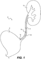
- FIG. 1 illustrates a stent 100 according to an example embodiment of the present invention.
- the stent 100 is illustrated inside a urinary tract 10 of a patient.
- One end of the stent 100 is placed inside a kidney 12 of the patient, and the opposing end is placed inside a bladder 14 of the patient.
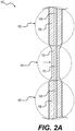
- FIG. 2A illustrates a portion of a stent 100 according to certain embodiments.
- the stent 100 may comprise a first section 102 and a second section 104.
- the first section 102 may include a first wall 106 defining a first luminal section 108.
- the second section 104 may include a second wall 110 defining a second luminal section 112.
- the first and the second sections may be placed in the urinary tract 10 of the patient.
- the second section 104 can be placed in the bladder 14.
- the second section 104 can be placed in the ureter section 16.
- the first and the second sections generally may be hollow members that include an opening or lumen that extends from one retaining end to another end.
- the first luminal section 108 and the second luminal section 112 may function to allow a wire to pass through the tubular member to assist with inserting and removing the stent in the patient.
- the first luminal section 108 and the second luminal section 112 may have a suitable size or diameter to be able to insert and remove the wire.
- the diameter of the first luminal section 108 and the second luminal section 112 may be on the order of about 0.040 inches to about 0.045 inches; however, larger and smaller sizes may be used depending on the specific use for the stent.
- the first luminal section 108 and the second luminal section 112 may also function to allow urine or other fluids to pass from the kidney 12 to the bladder 14.
- the first wall 106 and the second wall 110 may have any suitable thicknesses.
- the thickness of the first wall 106 generally may be constant. In some embodiments, the thickness of the first wall 106 may vary through the stent.
- the thickness of the second wall 110 may vary or change along its length between larger and smaller cross sections, or different shapes. In some embodiments, the thickness of the second wall 110 is less than the first wall 106.
- the thickness of the first wall 106 or the second wall 110 could be on the order from about 0.1 mm to about 1.8 mm. In some configurations, it may be preferable for the diameter of the first wall and/or the second wall to be less than to 2.3 mm.
- the size of the second section 104 and/or first section 102 may have a French size (F) on the order from about 1F to about 16F; however, larger or smaller French sizes may be considered depending on the specific application of the stent.
- the length of the stent 100 may be on the order of about 50 mm to about 350 mm; however, longer or shorter lengths may be considered depending on the specific application of the stent.
- FIG. 2B illustrates a stent 200, such as the stent 100 of FIG. 2A , at times when external pressure is applied to the stent 200 according to certain embodiments.
- the external pressure can be a pressure of peristalsis of the ureter contraction, fluidic pressure around the stent in the ureter, or the fluidic pressure in the bladder.
- the second section 204 is substantially closed due to the external pressure, while the first section 102 is open to pass fluid.
- the second section 104 of the stent 100 is enabled to substantially close at times external pressure is applied to the stent 100.
- the second section 104 of the stent 100 can be closed under external pressure.
- the closing may occur due to the difference in material properties, e.g., various geometries, non-uniformity of material, dimensions, etc.
- the fluid e.g., urine
- the second section 104 may act as a one-way valve.
- the second wall 110 of the second section 104/204 can be made of a material with a lower durometer than the first wall 106 of the first section 102; therefore, assisting in allowing the second section 104 to close under pressure.
- the second section 104/204 may have a second wall 110/210 having lesser thickness than the first wall 106.
- the first luminal section 108 and the second luminal section 112 may have any cross-sectional size or shape.
- the first luminal section and/or the second luminal section may be circular, round, spherical, rectangular, square, or a combination thereof in cross-section.
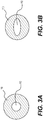
- FIGS. 3A and 3B illustrate cross sectional views of a portion of a stent, such as the stent 100 illustrated in FIG. 2A , according to certain embodiments.
- FIG. 3A illustrates the stent 100 having a circular cross section.
- FIG. 3B illustrates the stent 100 having oval or semi oval cross section.
- the stent 100 can have a round outer surface, i.e., cylindrical shape, and an oval shape luminal section 112.
- the first section 102 and the second section 104 may have any suitable cross section.
- the cross section of the first section 102 and the second section 104 may be generally round or circular, hexagonal, elliptical, oval, or any geometry shape.
- the cross section generally may be consistent between the two opposing ends (i.e., generally round along an entire length of the stent 100); or the cross section of the first section 102 and the second section 104 generally may be inconsistent along an entire length thereof (i.e., some portions of the stent may have a generally round cross section and then other parts may have an oval or flat cross section).
- the stent 100 is adapted to minimize tissue irritation by way of reducing the contact areas between the stent 100 and tissue, such as the ureter 16, or the bladder 14. In some embodiments, the stent 100 is adapted to minimize tissue irritation by way of increasing flexibility using material with various durometer in the stent 100.
- FIG. 4 illustrates a stent 300 having a first section 302 and a second section 304.
- the second section 304 may have a plurality of sections having respective walls 310 defining luminal sections 312 enabled to substantially close at times when external pressure is applied to the stent 300.
- the stent may be made of one or more materials.
- the one or more materials of the stent may resist tissue adherence and encrustation.
- the one or more materials may be soft or flexible such that the stent and/or retaining ends may conform to a lumen or passageway of a patient into which the stent is inserted.
- the one or more materials may be strong enough such that the stent and/or retaining ends provide support for the body passageway or maintain the body passageway at a certain diameter.
- the one or more materials of the stent, the first section, and the second section may comprise Chitosan, silicone, polyurethane, polyethylene blend, polytetrafluoroethylene (PTFE), thermoplastic polyurethane (TPU), polyolefin elastomer (POE), Ethylene-vinyl acetate (EVA), Polystyrene-butadiene-styrene (SBS), silicone rubber, Nylon, Polyethylene or polythene (PE), polypropylene (PP), thermoplastics, C-FlexTM, PercuflexTM, TecoflexTM; Pebax®, stainless steel, metal, a metal alloy, Nitinol materials, nickel, titanium alloy super alloy, chromium cobalt, or a combination thereof.
- PTFE polytetrafluoroethylene
- TPU thermoplastic polyurethane
- POE polyolefin elastomer
- EVA Ethylene-vinyl acetate
- SBS Poly
- the material may comprise a shape memory material.
- the first section and/or the second section may comprise two or more materials (i.e., dual durometer or multi-durometer) that transition from a firm material at the tubular member to a soft or flexible material at the retaining ends.
- the material may be a swelling polymer that is adapted to expand when in contact with a fluid or when subjected to an increase in temperature, such as for example when the stent is located inside the patient.
- the stent may be inserted or implanted inside a patient according to a method.
- the method may include a step of inserting a guide wire into the patient and advancing the guidewire into the bladder and then into the kidney.
- the method then includes a step of loading or feeding the stent onto the guidewire.
- the method includes a step of pushing or feeding the stent along the guidewire into the patient.
- the stent then may remain inside the patient to allow the ureter to dilate, which may provide for the stone or stone fragments to pass and allow urine to flow from the kidney to the bladder.
- the stent may remain permanently in the patient.
- the stent may be made of a biodegradable material where the stent dissolves or degrades inside the patient over time.
- the stent may be removed from the patient by inserting another guidewire into the patient and through the stent.
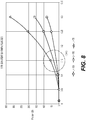
- FIGs. 5-10 are graphs plotting Pressure (Pcr) applied to the stent vs. thickness of a section of stent (t); according to various example embodiment combinations of stent French size and materials.
- FIGs. 5-10 illustrate computational modeling data for stents having a second section with three different lengths that made from materials with various modulus of elasticity, which closes at various wall thicknesses. That is, the second section of the stent can close at times when the external pressure of about 40-60 cm H2O is applied to the stent.
- a pressure in the renal artery during initial perfusion or passage of fluid through in the kidneys is on the order of about 40-60 cm H2O.
- a first stent having a second section with a length of 300 mm does not fell within the external pressure range of 40 cm H2O to 60 cm H2O
- a second stent having a second section with a length of 150 mm fell within the pressure range of 40 cm H2O to 60 cm H2O at a wall thickness about 0.23 mm to 0.27 mm.
- a third stent having a second section with a length of 75 mm fell within the pressure range of 40 cm H2O to 60 cm H2O at a wall thickness about 0.17 mm to 0.2 mm
- a first stent having a second section with a length of 300 mm does not fell within the external pressure range of 40 cm H2O to 60 cm H2O
- a second stent having a second section with a length of 150 mm fell within the pressure range of 40 cm H2O to 60 cm H2O at a wall thickness about 0.22 mm to 0.26 mm
- a third stent having a second section with a length of 75 mm fell within the pressure range of 40 cm H2O to 60 cm H2O at a wall thickness about 0.17 mm to 0.2 mm
- a first stent having a second section with a length of 300 mm fell within the external pressure range of 40 cm H2O to 60 cm H2O at a wall thickness of about 0.47 mm to 0.51 mm
- a second stent having a second section with a length of 150 mm fell within the pressure range of 40 cm H2O to 60 cm H2O at a wall thickness about 0.34 mm to 0.38 mm
- a third stent having a second section with a length of 75 mm fell within the pressure range of 40 cm H2O to 60 cm H2O at a wall thickness about 0.25 mm to 0.3 mm
- a first stent having a second section with a length of 300 mm fell within the external pressure range of 40 cm H2O to 60 cm H2O at a wall thickness of about 0.23 mm to 0.25 mm
- a second stent having a second section with a length of 150 mm fell within the pressure range of 40 cm H2O to 60 cm H2O at a wall thickness about 0.15 mm to 0.17 mm
- a third stent having a second section with a length of 75 mm fell within the pressure range of 40 cm H2O to 60 cm H2O at a wall thickness about 0.12 mm to 0.15 mm
- a first stent having a second section with a length of 300 mm fell within the external pressure range of 40 cm H2O to 60 cm H2O at a wall thickness of about 0.4 mm to 0.5 mm
- a second stent having a second section with a length of 150 mm fell within the pressure range of 40 cm H2O to 60 cm H2O at a wall thickness about 0.33 mm to 0.36 mm
- a third stent having a second section with a length of 75 mm fell within the pressure range of 40 cm H2O to 60 cm H2O at a wall thickness about 0.25 mm to 0.3 mm
- a first stent having a second section with a length of 300 mm fell within the external pressure range of 40 cm H2O to 60 cm H2O at a wall thickness of about 0.18 mm to 0.25 mm
- a second stent having a second section with a length of 150 mm fell within the pressure range of 40 cm H2O to 60 cm H2O at a wall thickness about 0.14 mm to 0.17 mm
- a third stent having a second section with a length of 75 mm fell within the pressure range of 40 cm H2O to 60 cm H2O at a wall thickness about 0.13 mm to 0.15 mm
- first, second, third, etc. may be used herein to describe various elements, components, regions, layers and/or sections, these elements, components, regions, layers and/or sections should not be limited by these terms. These terms may be used to distinguish one element, component, region, layer or section from another region, layer or section. Terms such as “first,” “second,” and other numerical terms when used herein do not imply a sequence or order unless clearly indicated by the context. Thus, a first element, component, region, layer or section discussed below could be termed a second element, component, region, layer or section without departing from the teachings.
- spatially relative terms such as “inner,” “outer,” “beneath,” “below,” “lower,” “above,” “upper,” and the like, may be used herein for ease of description to describe one element or feature's relationship to another element(s) or feature(s) as illustrated in the figures.
- Spatially relative terms may be intended to encompass different orientations of the device in use or operation in addition to the orientation depicted in the figures. For example, if the device in the figures is turned over, elements described as “below” or “beneath” other elements or features would then be oriented “above” the other elements or features.
- the example term “below” can encompass both an orientation of above and below.
- the device may be otherwise oriented (rotated 90 degrees or at other orientations) and the spatially relative descriptors used herein interpreted accordingly.
Landscapes
- Health & Medical Sciences (AREA)
- Heart & Thoracic Surgery (AREA)
- Life Sciences & Earth Sciences (AREA)
- Animal Behavior & Ethology (AREA)
- General Health & Medical Sciences (AREA)
- Public Health (AREA)
- Veterinary Medicine (AREA)
- Biomedical Technology (AREA)
- Engineering & Computer Science (AREA)
- Vascular Medicine (AREA)
- Cardiology (AREA)
- Urology & Nephrology (AREA)
- Hematology (AREA)
- Oral & Maxillofacial Surgery (AREA)
- Transplantation (AREA)
- Anesthesiology (AREA)
- Otolaryngology (AREA)
- Ophthalmology & Optometry (AREA)
- Pulmonology (AREA)
- Surgery (AREA)
- Epidemiology (AREA)
- Gastroenterology & Hepatology (AREA)
- Prostheses (AREA)
- Media Introduction/Drainage Providing Device (AREA)
Abstract
Description
- The present disclosure relates to a medical device, and more particularly to a ureteral stent.
- A ureteral stent may be placed inside a patient to assist in urinary drainage from a kidney to a bladder. For example, after some ureteral stone procedures, pieces or fragments of the stone or tumor can drop down into the ureter which may disrupt or block the flow of urine from the kidney to the bladder. The ureteral stent may function to allow the ureter to dilate and provide for the stone or stone fragments to pass and allow urine to flow from the kidney to the bladder.
- A ureteral stent generally comprises a tubular member that terminates at two opposing ends. The tubular member allows the urine to flow through. However, current stents can cause significant discomfort to patients during voiding.
- It may therefore be desirable to improve the current state of the art by providing a ureteral stent that can be placed inside a patient to provide a passageway for urinary drainage from a kidney to a bladder, while minimizing discomfort to the patient.
- The present disclosure provides a ureteral stent which significantly minimizes discomfort to a patient during voiding. A possible cause of discomfort can occur during drainage of urine through a stent. When the bladder muscles push urine out, some part of the urine can flow back to the kidney through the stent. Back flow of the urine to the kidney can be the possible cause of flank pain.
- According to certain embodiments, a stent is provided. The stent may include a first section having a first wall defining a first luminal section and a second section having a second wall defining a second luminal section. The second section may be enabled to substantially close at times when external pressure is applied to the stent.
- Objects, features, and advantages of embodiments disclosed herein may be better understood by referring to the following description in conjunction with the accompanying drawings. The drawings are not meant to limit the scope of the claims included herewith. For clarity, not every element may be labeled in every figure. The drawings are not necessarily to scale, emphasis instead being placed upon illustrating embodiments, principles, and concepts. Thus, features and advantages of the present disclosure will become more apparent from the following detailed description of exemplary embodiments thereof taken in conjunction with the accompanying drawings.
-
FIG. 1 is an illustration of a ureteral stent according to certain embodiment of the present invention placed in a kidney, a ureter, and a bladder of a patient. -
FIGS. 2A-2B are sectional views of a portion of a stent, according to certain embodiments. -
FIGS. 3A-3B are cross sectional views of a portion of a stent, according to certain embodiments. -
FIG. 4 is a sectional view of a portion of a stent, according to certain embodiments. -
FIGS. 5-10 are graphs plotting Pressure (Pcr) applied to the stent vs. thickness of a section of stent (t); according to various example embodiment combinations of stent French size and materials. - These teachings are directed to a stent. The stent may be a medical stent. The stent may be any stent, such as a ureteral stent. The ureteral stent may function to assist in fluid or urinary drainage from the kidney to the bladder in patients. For example, after some ureteral stone or tumor medical procedures, pieces or fragments of the stone or tumor can drop down into the ureter, which may disrupt or block the flow of urine from the kidney to the bladder. The ureteral stent may function to allow the ureter to dilate, which may provide for the stone or stone fragments to pass and allow fluid or urine to flow from the kidney to the bladder.
-
FIG. 1 illustrates astent 100 according to an example embodiment of the present invention. Thestent 100 is illustrated inside aurinary tract 10 of a patient. One end of thestent 100 is placed inside akidney 12 of the patient, and the opposing end is placed inside abladder 14 of the patient. -
FIG. 2A illustrates a portion of astent 100 according to certain embodiments. Thestent 100 may comprise afirst section 102 and asecond section 104. Thefirst section 102 may include afirst wall 106 defining a firstluminal section 108. Thesecond section 104 may include asecond wall 110 defining a secondluminal section 112. The first and the second sections may be placed in theurinary tract 10 of the patient. Thesecond section 104 can be placed in thebladder 14. In some embodiments, thesecond section 104 can be placed in theureter section 16. The first and the second sections generally may be hollow members that include an opening or lumen that extends from one retaining end to another end. - The first
luminal section 108 and the secondluminal section 112 may function to allow a wire to pass through the tubular member to assist with inserting and removing the stent in the patient. The firstluminal section 108 and the secondluminal section 112 may have a suitable size or diameter to be able to insert and remove the wire. The diameter of the firstluminal section 108 and the secondluminal section 112 may be on the order of about 0.040 inches to about 0.045 inches; however, larger and smaller sizes may be used depending on the specific use for the stent. Once inserted into the patient, the firstluminal section 108 and the secondluminal section 112 may also function to allow urine or other fluids to pass from thekidney 12 to thebladder 14. - The
first wall 106 and thesecond wall 110 may have any suitable thicknesses. The thickness of thefirst wall 106 generally may be constant. In some embodiments, the thickness of thefirst wall 106 may vary through the stent. The thickness of thesecond wall 110 may vary or change along its length between larger and smaller cross sections, or different shapes. In some embodiments, the thickness of thesecond wall 110 is less than thefirst wall 106. - In some embodiments, the thickness of the
first wall 106 or thesecond wall 110 could be on the order from about 0.1 mm to about 1.8 mm. In some configurations, it may be preferable for the diameter of the first wall and/or the second wall to be less than to 2.3 mm. The size of thesecond section 104 and/orfirst section 102 may have a French size (F) on the order from about 1F to about 16F; however, larger or smaller French sizes may be considered depending on the specific application of the stent. - The length of the
stent 100 may be on the order of about 50 mm to about 350 mm; however, longer or shorter lengths may be considered depending on the specific application of the stent. -
FIG. 2B illustrates astent 200, such as thestent 100 ofFIG. 2A , at times when external pressure is applied to thestent 200 according to certain embodiments. The external pressure can be a pressure of peristalsis of the ureter contraction, fluidic pressure around the stent in the ureter, or the fluidic pressure in the bladder. AsFIG. 2B illustrates, thesecond section 204 is substantially closed due to the external pressure, while thefirst section 102 is open to pass fluid. In one embodiment, thesecond section 104 of thestent 100 is enabled to substantially close at times external pressure is applied to thestent 100. Thesecond section 104 of thestent 100 can be closed under external pressure. The closing may occur due to the difference in material properties, e.g., various geometries, non-uniformity of material, dimensions, etc. By closing thesecond section 104 of thestent 100, the fluid, e.g., urine, cannot go back toward thekidney 12 through thestent 100. The back flow of the urine and/or fluid to the kidney may cause significant discomfort to the patient. Accordingly, thesecond section 104 may act as a one-way valve. - In some embodiments, the
second wall 110 of thesecond section 104/204 can be made of a material with a lower durometer than thefirst wall 106 of thefirst section 102; therefore, assisting in allowing thesecond section 104 to close under pressure. In some embodiments, thesecond section 104/204 may have asecond wall 110/210 having lesser thickness than thefirst wall 106. - The first
luminal section 108 and the secondluminal section 112 may have any cross-sectional size or shape. For example, the first luminal section and/or the second luminal section may be circular, round, spherical, rectangular, square, or a combination thereof in cross-section. -
FIGS. 3A and 3B illustrate cross sectional views of a portion of a stent, such as thestent 100 illustrated inFIG. 2A , according to certain embodiments.FIG. 3A illustrates thestent 100 having a circular cross section.FIG. 3B illustrates thestent 100 having oval or semi oval cross section. As shown inFIG. 3B , thestent 100 can have a round outer surface, i.e., cylindrical shape, and an oval shapeluminal section 112. - The
first section 102 and thesecond section 104 may have any suitable cross section. For example, the cross section of thefirst section 102 and thesecond section 104 may be generally round or circular, hexagonal, elliptical, oval, or any geometry shape. The cross section generally may be consistent between the two opposing ends (i.e., generally round along an entire length of the stent 100); or the cross section of thefirst section 102 and thesecond section 104 generally may be inconsistent along an entire length thereof (i.e., some portions of the stent may have a generally round cross section and then other parts may have an oval or flat cross section). - In some embodiments, the
stent 100 is adapted to minimize tissue irritation by way of reducing the contact areas between thestent 100 and tissue, such as theureter 16, or thebladder 14. In some embodiments, thestent 100 is adapted to minimize tissue irritation by way of increasing flexibility using material with various durometer in thestent 100. -
FIG. 4 illustrates astent 300 having afirst section 302 and asecond section 304. Thesecond section 304 may have a plurality of sections havingrespective walls 310 definingluminal sections 312 enabled to substantially close at times when external pressure is applied to thestent 300. - In some embodiments, the stent may be made of one or more materials. The one or more materials of the stent may resist tissue adherence and encrustation. The one or more materials may be soft or flexible such that the stent and/or retaining ends may conform to a lumen or passageway of a patient into which the stent is inserted. The one or more materials may be strong enough such that the stent and/or retaining ends provide support for the body passageway or maintain the body passageway at a certain diameter.
- According to certain embodiments, the one or more materials of the stent, the first section, and the second section may comprise Chitosan, silicone, polyurethane, polyethylene blend, polytetrafluoroethylene (PTFE), thermoplastic polyurethane (TPU), polyolefin elastomer (POE), Ethylene-vinyl acetate (EVA), Polystyrene-butadiene-styrene (SBS), silicone rubber, Nylon, Polyethylene or polythene (PE), polypropylene (PP), thermoplastics, C-Flex™, Percuflex™, Tecoflex™; Pebax®, stainless steel, metal, a metal alloy, Nitinol materials, nickel, titanium alloy super alloy, chromium cobalt, or a combination thereof. The material may comprise a shape memory material. The first section and/or the second section may comprise two or more materials (i.e., dual durometer or multi-durometer) that transition from a firm material at the tubular member to a soft or flexible material at the retaining ends. The material may be a swelling polymer that is adapted to expand when in contact with a fluid or when subjected to an increase in temperature, such as for example when the stent is located inside the patient.
- The stent may be inserted or implanted inside a patient according to a method. The method may include a step of inserting a guide wire into the patient and advancing the guidewire into the bladder and then into the kidney. The method then includes a step of loading or feeding the stent onto the guidewire. The method includes a step of pushing or feeding the stent along the guidewire into the patient. The stent then may remain inside the patient to allow the ureter to dilate, which may provide for the stone or stone fragments to pass and allow urine to flow from the kidney to the bladder. The stent may remain permanently in the patient. The stent may be made of a biodegradable material where the stent dissolves or degrades inside the patient over time. The stent may be removed from the patient by inserting another guidewire into the patient and through the stent.
-
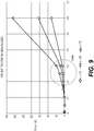
FIGs. 5-10 are graphs plotting Pressure (Pcr) applied to the stent vs. thickness of a section of stent (t); according to various example embodiment combinations of stent French size and materials.FIGs. 5-10 illustrate computational modeling data for stents having a second section with three different lengths that made from materials with various modulus of elasticity, which closes at various wall thicknesses. That is, the second section of the stent can close at times when the external pressure of about 40-60 cm H2O is applied to the stent. - Flugge's formulation (EQ. 1 below) for the linear theory of orthotropic cylindrical shell was adopted to calculate instability of the
stent 100 under external pressure. The external pressure may be fluid passing through or around thestent 100, movement of the patient, etc.
- In EQ. 1 above, R = radius of the stent 100 (mm); L=length of stent 100 (mm); t=thickness of stent 100 (mm); Pcr=critical pressure (cmH2O, 1MPa=10197.2 cmH2O); E= modulus of elasticity (MPa); and µ=Poisson's ratio (µ=0.5 was selected).
- A pressure in the renal artery during initial perfusion or passage of fluid through in the kidneys is on the order of about 40-60 cm H2O.
- Referring specifically to
FIG. 5 , three different stents having a 5 Fr. size made of EVA material having a modulus of elasticity of 11 MPa were tested. - As illustrated in
FIG. 5 , a first stent having a second section with a length of 300 mm does not fell within the external pressure range of 40 cm H2O to 60 cm H2O A second stent having a second section with a length of 150 mm fell within the pressure range of 40 cm H2O to 60 cm H2O at a wall thickness about 0.23 mm to 0.27 mm. A third stent having a second section with a length of 75 mm fell within the pressure range of 40 cm H2O to 60 cm H2O at a wall thickness about 0.17 mm to 0.2 mm - Referring specifically to
FIG. 6 , three different stents having a 5 Fr. size made of TPU material having a modulus of elasticity of 12 MPa were tested. - As illustrated in
FIG. 6 , a first stent having a second section with a length of 300 mm does not fell within the external pressure range of 40 cm H2O to 60 cm H2O A second stent having a second section with a length of 150 mm fell within the pressure range of 40 cm H2O to 60 cm H2O at a wall thickness about 0.22 mm to 0.26 mm A third stent having a second section with a length of 75 mm fell within the pressure range of 40 cm H2O to 60 cm H2O at a wall thickness about 0.17 mm to 0.2 mm - Referring specifically to
FIG. 7 , three different stents having a 8 Fr. size made of EVA material having a modulus of elasticity of 11 MPa were tested. - As illustrated in
FIG. 7 , a first stent having a second section with a length of 300 mm fell within the external pressure range of 40 cm H2O to 60 cm H2O at a wall thickness of about 0.47 mm to 0.51 mm A second stent having a second section with a length of 150 mm fell within the pressure range of 40 cm H2O to 60 cm H2O at a wall thickness about 0.34 mm to 0.38 mm A third stent having a second section with a length of 75 mm fell within the pressure range of 40 cm H2O to 60 cm H2O at a wall thickness about 0.25 mm to 0.3 mm - Referring specifically to
FIG. 8 , three different stents having a 8 Fr. size made of EVA material having a modulus of elasticity of 70 MPa were tested. - As illustrated in
FIG. 8 , a first stent having a second section with a length of 300 mm fell within the external pressure range of 40 cm H2O to 60 cm H2O at a wall thickness of about 0.23 mm to 0.25 mm A second stent having a second section with a length of 150 mm fell within the pressure range of 40 cm H2O to 60 cm H2O at a wall thickness about 0.15 mm to 0.17 mm A third stent having a second section with a length of 75 mm fell within the pressure range of 40 cm H2O to 60 cm H2O at a wall thickness about 0.12 mm to 0.15 mm - Referring specifically to
FIG. 9 , three different stents having a 8 Fr. size made of TPU material having a modulus of elasticity of 12 MPa were tested. - As illustrated in
FIG. 9 , a first stent having a second section with a length of 300 mm fell within the external pressure range of 40 cm H2O to 60 cm H2O at a wall thickness of about 0.4 mm to 0.5 mm A second stent having a second section with a length of 150 mm fell within the pressure range of 40 cm H2O to 60 cm H2O at a wall thickness about 0.33 mm to 0.36 mm A third stent having a second section with a length of 75 mm fell within the pressure range of 40 cm H2O to 60 cm H2O at a wall thickness about 0.25 mm to 0.3 mm - Referring specifically to
FIG. 10 , three different stents having a 8 Fr. size made of Pebax® material having a modulus of elasticity of 81 MPa were tested. - As illustrated in
FIG. 10 , a first stent having a second section with a length of 300 mm fell within the external pressure range of 40 cm H2O to 60 cm H2O at a wall thickness of about 0.18 mm to 0.25 mm A second stent having a second section with a length of 150 mm fell within the pressure range of 40 cm H2O to 60 cm H2O at a wall thickness about 0.14 mm to 0.17 mm A third stent having a second section with a length of 75 mm fell within the pressure range of 40 cm H2O to 60 cm H2O at a wall thickness about 0.13 mm to 0.15 mm - The explanations and illustrations presented herein are intended to acquaint others skilled in the art with the invention, its principles, and its practical application. The above description is intended to be illustrative and not restrictive. Those skilled in the art may adapt and apply the invention in its numerous forms, as may be best suited to the requirements of a particular use.
- Accordingly, the specific embodiments of the present invention as set forth are not intended as being exhaustive or limiting of the teachings. The scope of the teachings should, therefore, be determined not with reference to this description, but should instead be determined with reference to the appended claims, along with the full scope of equivalents to which such claims are entitled. The omission in the following claims of any aspect of subject matter that is disclosed herein is not a disclaimer of such subject matter, nor should it be regarded that the inventors did not consider such subject matter to be part of the disclosed inventive subject matter.
- Plural elements or steps can be provided by a single integrated element or step. Alternatively, a single element or step might be divided into separate plural elements or steps.
- The disclosure of "a" or "one" to describe an element or step is not intended to foreclose additional elements or steps.
- By use of the term "may" herein, it is intended that any described attributes that "may" be included are optional.
- While the terms first, second, third, etc., may be used herein to describe various elements, components, regions, layers and/or sections, these elements, components, regions, layers and/or sections should not be limited by these terms. These terms may be used to distinguish one element, component, region, layer or section from another region, layer or section. Terms such as "first," "second," and other numerical terms when used herein do not imply a sequence or order unless clearly indicated by the context. Thus, a first element, component, region, layer or section discussed below could be termed a second element, component, region, layer or section without departing from the teachings.
- Spatially relative terms, such as "inner," "outer," "beneath," "below," "lower," "above," "upper," and the like, may be used herein for ease of description to describe one element or feature's relationship to another element(s) or feature(s) as illustrated in the figures. Spatially relative terms may be intended to encompass different orientations of the device in use or operation in addition to the orientation depicted in the figures. For example, if the device in the figures is turned over, elements described as "below" or "beneath" other elements or features would then be oriented "above" the other elements or features. Thus, the example term "below" can encompass both an orientation of above and below. The device may be otherwise oriented (rotated 90 degrees or at other orientations) and the spatially relative descriptors used herein interpreted accordingly.
- The disclosures of all articles and references, including patent applications and publications, are incorporated by reference for all purposes. Other combinations are also possible as will be gleaned from the following claims, which are also hereby incorporated by reference into this written description.
Claims (10)
- A stent comprising:a first section (102) having a first wall (106) defining a first luminal section (108); anda second section (104), longitudinally separated from the first section (102), having a second wall (110) defining a second luminal section (112), enabled to substantially close at times when external pressure is applied to the stent.
- The stent of claim 1, wherein the second wall (110) has lower durometer than the first wall (106).
- The stent of any of claims 1 or 2, wherein the first wall (106) and the second wall (110) are made of a polymer.
- The stent of any of claims 1 to 3, wherein the second wall (110) is made of chitosan.
- The stent of any of claims 1 to 4, wherein the first wall (106) is thicker than the second wall (110).
- The stent of any of claims 1 to 5, wherein the stent is a ureteral stent.
- The stent of claim 6, wherein the second section (104) is placed in a bladder of a patient.
- The stent of claim 6, wherein the second section (104) is placed in a ureter of a patient.
- The stent of any of claims 1 to 8, wherein the external pressure is about 30 MPa to 70 MPa.
- The stent of any of claims 1 to 9, wherein the second section (304) further comprises plurality of walls (310) defining luminal sections enabled to substantially close at times when external pressure is applied to the stent.
Priority Applications (1)
| Application Number | Priority Date | Filing Date | Title |
|---|---|---|---|
| EP21175131.8A EP3925658A1 (en) | 2018-03-30 | 2019-03-23 | Ureteral stent |
Applications Claiming Priority (1)
| Application Number | Priority Date | Filing Date | Title |
|---|---|---|---|
| US15/941,598 US11318289B2 (en) | 2018-03-30 | 2018-03-30 | Ureteral stent |
Related Child Applications (1)
| Application Number | Title | Priority Date | Filing Date |
|---|---|---|---|
| EP21175131.8A Division EP3925658A1 (en) | 2018-03-30 | 2019-03-23 | Ureteral stent |
Publications (2)
| Publication Number | Publication Date |
|---|---|
| EP3546017A1 true EP3546017A1 (en) | 2019-10-02 |
| EP3546017B1 EP3546017B1 (en) | 2021-05-26 |
Family
ID=65911030
Family Applications (2)
| Application Number | Title | Priority Date | Filing Date |
|---|---|---|---|
| EP19164772.6A Active EP3546017B1 (en) | 2018-03-30 | 2019-03-23 | Ureteral stent |
| EP21175131.8A Pending EP3925658A1 (en) | 2018-03-30 | 2019-03-23 | Ureteral stent |
Family Applications After (1)
| Application Number | Title | Priority Date | Filing Date |
|---|---|---|---|
| EP21175131.8A Pending EP3925658A1 (en) | 2018-03-30 | 2019-03-23 | Ureteral stent |
Country Status (5)
| Country | Link |
|---|---|
| US (2) | US11318289B2 (en) |
| EP (2) | EP3546017B1 (en) |
| JP (2) | JP7451089B2 (en) |
| CN (1) | CN110327140B (en) |
| ES (1) | ES2882561T3 (en) |
Cited By (1)
| Publication number | Priority date | Publication date | Assignee | Title |
|---|---|---|---|---|
| US11318289B2 (en) | 2018-03-30 | 2022-05-03 | Gyrus Acmi, Inc. | Ureteral stent |
Families Citing this family (1)
| Publication number | Priority date | Publication date | Assignee | Title |
|---|---|---|---|---|
| CN116059001A (en) * | 2022-12-01 | 2023-05-05 | 滨州医学院烟台附属医院 | an artificial ureter |
Citations (5)
| Publication number | Priority date | Publication date | Assignee | Title |
|---|---|---|---|---|
| WO2001091668A1 (en) * | 2000-05-26 | 2001-12-06 | Scimed Life Systems, Inc. | Ureteral stent |
| WO2002089893A1 (en) * | 2001-05-04 | 2002-11-14 | Scimed Life Systems, Inc. | Drainage devices and methods |
| US20030195456A1 (en) * | 2002-04-16 | 2003-10-16 | Robertson David W. | Ureteral stent with end-effector and related methods |
| US20030199986A1 (en) * | 2002-04-18 | 2003-10-23 | Scimed Life Systems, Inc. | Anti-reflux ureteral stents and methods |
| US20060259151A1 (en) * | 2005-05-11 | 2006-11-16 | Tim Ward | Ureteral stent with conforming retention structure |
Family Cites Families (21)
| Publication number | Priority date | Publication date | Assignee | Title |
|---|---|---|---|---|
| US4553959A (en) | 1982-01-27 | 1985-11-19 | The Victoria University Of Manchester | Urethral catheter |
| DE4236571A1 (en) * | 1992-10-29 | 1994-05-05 | Hans Prof Dr Med Sachse | Tubular ureteral splint |
| US6991614B2 (en) * | 1995-11-07 | 2006-01-31 | Boston Scientific Scimed, Inc. | Ureteral stent for improved patient comfort |
| US6582472B2 (en) * | 1997-02-26 | 2003-06-24 | Applied Medical Resources Corporation | Kinetic stent |
| US20080086214A1 (en) * | 1998-08-31 | 2008-04-10 | Wilson-Cook Medical Inc. | Medical device having a sleeve valve with bioactive agent |
| US6719804B2 (en) * | 2001-04-02 | 2004-04-13 | Scimed Life Systems, Inc. | Medical stent and related methods |
| US6887215B2 (en) * | 2001-06-01 | 2005-05-03 | Boston Scientific Scimed, Inc. | Compressible ureteral stent for comfort |
| US7044981B2 (en) * | 2003-01-22 | 2006-05-16 | Boston Scientific Scimed, Inc. | Ureteral stent configured for improved patient comfort and aftercare |
| AU2004277970A1 (en) * | 2003-09-30 | 2005-04-14 | Merit Medical Systems, Inc. | Active stent |
| US7470247B2 (en) | 2004-04-26 | 2008-12-30 | Gyrus Acmi, Inc. | Ureteral stent |
| US9789293B2 (en) * | 2010-06-24 | 2017-10-17 | Boston Scientific Scimed, Inc. | Stents with bladder retention members |
| US9492266B2 (en) * | 2010-08-05 | 2016-11-15 | Taris Biomedical Llc | Ureteral stent drug delivery device, kit, and method |
| US20140052272A1 (en) * | 2012-08-20 | 2014-02-20 | Boston Scientific Scimed, Inc. | Comfort stents |
| US9127526B2 (en) * | 2012-12-03 | 2015-09-08 | Halliburton Energy Services, Inc. | Fast pressure protection system and method |
| EP2749308B1 (en) * | 2012-12-28 | 2016-04-27 | Cook Medical Technologies LLC | Hollow fiber ureteral stent |
| CN204246651U (en) * | 2014-11-17 | 2015-04-08 | 江苏省人民医院 | A kind of easy-to-displaceable ureter rack tube |
| US9878817B2 (en) | 2014-12-24 | 2018-01-30 | Dryip, Llc | Enhanced strength partitioned container |
| WO2016185482A1 (en) * | 2015-05-20 | 2016-11-24 | Innoventions Ltd. | Stent and method of use |
| US10517710B2 (en) * | 2015-12-03 | 2019-12-31 | Cook Medical Technologies Llc | Helical hollow strand ureteral stent |
| SE540134C2 (en) * | 2017-04-04 | 2018-04-10 | Madeleine Ramstedt | Indwelling urethral device |
| US11318289B2 (en) | 2018-03-30 | 2022-05-03 | Gyrus Acmi, Inc. | Ureteral stent |
-
2018
- 2018-03-30 US US15/941,598 patent/US11318289B2/en active Active
-
2019
- 2019-03-23 EP EP19164772.6A patent/EP3546017B1/en active Active
- 2019-03-23 ES ES19164772T patent/ES2882561T3/en active Active
- 2019-03-23 EP EP21175131.8A patent/EP3925658A1/en active Pending
- 2019-03-27 CN CN201910236771.3A patent/CN110327140B/en active Active
- 2019-03-29 JP JP2019067338A patent/JP7451089B2/en active Active
-
2022
- 2022-04-04 US US17/657,895 patent/US12070564B2/en active Active
-
2024
- 2024-03-05 JP JP2024032956A patent/JP7669551B2/en active Active
Patent Citations (5)
| Publication number | Priority date | Publication date | Assignee | Title |
|---|---|---|---|---|
| WO2001091668A1 (en) * | 2000-05-26 | 2001-12-06 | Scimed Life Systems, Inc. | Ureteral stent |
| WO2002089893A1 (en) * | 2001-05-04 | 2002-11-14 | Scimed Life Systems, Inc. | Drainage devices and methods |
| US20030195456A1 (en) * | 2002-04-16 | 2003-10-16 | Robertson David W. | Ureteral stent with end-effector and related methods |
| US20030199986A1 (en) * | 2002-04-18 | 2003-10-23 | Scimed Life Systems, Inc. | Anti-reflux ureteral stents and methods |
| US20060259151A1 (en) * | 2005-05-11 | 2006-11-16 | Tim Ward | Ureteral stent with conforming retention structure |
Cited By (2)
| Publication number | Priority date | Publication date | Assignee | Title |
|---|---|---|---|---|
| US11318289B2 (en) | 2018-03-30 | 2022-05-03 | Gyrus Acmi, Inc. | Ureteral stent |
| US12070564B2 (en) | 2018-03-30 | 2024-08-27 | Gyrus Acmi, Inc. | Ureteral stent |
Also Published As
| Publication number | Publication date |
|---|---|
| JP2019181193A (en) | 2019-10-24 |
| US12070564B2 (en) | 2024-08-27 |
| JP7669551B2 (en) | 2025-04-28 |
| EP3546017B1 (en) | 2021-05-26 |
| ES2882561T3 (en) | 2021-12-02 |
| CN110327140A (en) | 2019-10-15 |
| US11318289B2 (en) | 2022-05-03 |
| CN110327140B (en) | 2024-10-11 |
| US20220226624A1 (en) | 2022-07-21 |
| JP7451089B2 (en) | 2024-03-18 |
| JP2024071402A (en) | 2024-05-24 |
| EP3925658A1 (en) | 2021-12-22 |
| US20190298978A1 (en) | 2019-10-03 |
Similar Documents
| Publication | Publication Date | Title |
|---|---|---|
| US11779737B2 (en) | Ureteral stent | |
| JP4327592B2 (en) | Catheter assembly | |
| CN111787871B (en) | flow control valve | |
| US20180272105A1 (en) | Urinary catheter having a conical proximal section | |
| EP1787675B1 (en) | An access member and a system for catheterization of the urinary bladder | |
| US10780243B2 (en) | Method and apparatus for treatment of human urinary incontinence | |
| US10252025B2 (en) | Urinary prostheses | |
| JP7669551B2 (en) | Ureteral stents | |
| US20080300544A1 (en) | Expandable sheath introducer | |
| JPWO2019049955A1 (en) | Urethral catheter | |
| EP4157419B1 (en) | One-piece intermittent catheters with variable thickness and handle feature | |
| US20020193742A1 (en) | Valved over-the-wire catheter | |
| JP2004505690A (en) | Balloonless urethral catheter | |
| JP2011206124A (en) | Balloon catheter | |
| KR101528418B1 (en) | Intubation tube | |
| US11224502B2 (en) | Ureteral stents and methods of using the same | |
| WO2021044546A1 (en) | Valve assembly and urethral catheter |
Legal Events
| Date | Code | Title | Description |
|---|---|---|---|
| PUAI | Public reference made under article 153(3) epc to a published international application that has entered the european phase |
Free format text: ORIGINAL CODE: 0009012 |
|
| STAA | Information on the status of an ep patent application or granted ep patent |
Free format text: STATUS: THE APPLICATION HAS BEEN PUBLISHED |
|
| AK | Designated contracting states |
Kind code of ref document: A1 Designated state(s): AL AT BE BG CH CY CZ DE DK EE ES FI FR GB GR HR HU IE IS IT LI LT LU LV MC MK MT NL NO PL PT RO RS SE SI SK SM TR |
|
| AX | Request for extension of the european patent |
Extension state: BA ME |
|
| STAA | Information on the status of an ep patent application or granted ep patent |
Free format text: STATUS: REQUEST FOR EXAMINATION WAS MADE |
|
| 17P | Request for examination filed |
Effective date: 20200402 |
|
| RBV | Designated contracting states (corrected) |
Designated state(s): AL AT BE BG CH CY CZ DE DK EE ES FI FR GB GR HR HU IE IS IT LI LT LU LV MC MK MT NL NO PL PT RO RS SE SI SK SM TR |
|
| GRAP | Despatch of communication of intention to grant a patent |
Free format text: ORIGINAL CODE: EPIDOSNIGR1 |
|
| STAA | Information on the status of an ep patent application or granted ep patent |
Free format text: STATUS: GRANT OF PATENT IS INTENDED |
|
| RIC1 | Information provided on ipc code assigned before grant |
Ipc: A61M 27/00 20060101AFI20201113BHEP |
|
| INTG | Intention to grant announced |
Effective date: 20201207 |
|
| GRAS | Grant fee paid |
Free format text: ORIGINAL CODE: EPIDOSNIGR3 |
|
| GRAA | (expected) grant |
Free format text: ORIGINAL CODE: 0009210 |
|
| STAA | Information on the status of an ep patent application or granted ep patent |
Free format text: STATUS: THE PATENT HAS BEEN GRANTED |
|
| AK | Designated contracting states |
Kind code of ref document: B1 Designated state(s): AL AT BE BG CH CY CZ DE DK EE ES FI FR GB GR HR HU IE IS IT LI LT LU LV MC MK MT NL NO PL PT RO RS SE SI SK SM TR |
|
| REG | Reference to a national code |
Ref country code: GB Ref legal event code: FG4D |
|
| REG | Reference to a national code |
Ref country code: CH Ref legal event code: EP |
|
| REG | Reference to a national code |
Ref country code: AT Ref legal event code: REF Ref document number: 1395603 Country of ref document: AT Kind code of ref document: T Effective date: 20210615 |
|
| REG | Reference to a national code |
Ref country code: DE Ref legal event code: R096 Ref document number: 602019004795 Country of ref document: DE |
|
| REG | Reference to a national code |
Ref country code: IE Ref legal event code: FG4D |
|
| REG | Reference to a national code |
Ref country code: LT Ref legal event code: MG9D |
|
| REG | Reference to a national code |
Ref country code: AT Ref legal event code: MK05 Ref document number: 1395603 Country of ref document: AT Kind code of ref document: T Effective date: 20210526 |
|
| PG25 | Lapsed in a contracting state [announced via postgrant information from national office to epo] |
Ref country code: BG Free format text: LAPSE BECAUSE OF FAILURE TO SUBMIT A TRANSLATION OF THE DESCRIPTION OR TO PAY THE FEE WITHIN THE PRESCRIBED TIME-LIMIT Effective date: 20210826 Ref country code: AT Free format text: LAPSE BECAUSE OF FAILURE TO SUBMIT A TRANSLATION OF THE DESCRIPTION OR TO PAY THE FEE WITHIN THE PRESCRIBED TIME-LIMIT Effective date: 20210526 Ref country code: HR Free format text: LAPSE BECAUSE OF FAILURE TO SUBMIT A TRANSLATION OF THE DESCRIPTION OR TO PAY THE FEE WITHIN THE PRESCRIBED TIME-LIMIT Effective date: 20210526 Ref country code: LT Free format text: LAPSE BECAUSE OF FAILURE TO SUBMIT A TRANSLATION OF THE DESCRIPTION OR TO PAY THE FEE WITHIN THE PRESCRIBED TIME-LIMIT Effective date: 20210526 Ref country code: FI Free format text: LAPSE BECAUSE OF FAILURE TO SUBMIT A TRANSLATION OF THE DESCRIPTION OR TO PAY THE FEE WITHIN THE PRESCRIBED TIME-LIMIT Effective date: 20210526 |
|
| REG | Reference to a national code |
Ref country code: NL Ref legal event code: MP Effective date: 20210526 |
|
| PG25 | Lapsed in a contracting state [announced via postgrant information from national office to epo] |
Ref country code: RS Free format text: LAPSE BECAUSE OF FAILURE TO SUBMIT A TRANSLATION OF THE DESCRIPTION OR TO PAY THE FEE WITHIN THE PRESCRIBED TIME-LIMIT Effective date: 20210526 Ref country code: SE Free format text: LAPSE BECAUSE OF FAILURE TO SUBMIT A TRANSLATION OF THE DESCRIPTION OR TO PAY THE FEE WITHIN THE PRESCRIBED TIME-LIMIT Effective date: 20210526 Ref country code: PT Free format text: LAPSE BECAUSE OF FAILURE TO SUBMIT A TRANSLATION OF THE DESCRIPTION OR TO PAY THE FEE WITHIN THE PRESCRIBED TIME-LIMIT Effective date: 20210927 Ref country code: PL Free format text: LAPSE BECAUSE OF FAILURE TO SUBMIT A TRANSLATION OF THE DESCRIPTION OR TO PAY THE FEE WITHIN THE PRESCRIBED TIME-LIMIT Effective date: 20210526 Ref country code: LV Free format text: LAPSE BECAUSE OF FAILURE TO SUBMIT A TRANSLATION OF THE DESCRIPTION OR TO PAY THE FEE WITHIN THE PRESCRIBED TIME-LIMIT Effective date: 20210526 Ref country code: NO Free format text: LAPSE BECAUSE OF FAILURE TO SUBMIT A TRANSLATION OF THE DESCRIPTION OR TO PAY THE FEE WITHIN THE PRESCRIBED TIME-LIMIT Effective date: 20210826 Ref country code: IS Free format text: LAPSE BECAUSE OF FAILURE TO SUBMIT A TRANSLATION OF THE DESCRIPTION OR TO PAY THE FEE WITHIN THE PRESCRIBED TIME-LIMIT Effective date: 20210926 Ref country code: GR Free format text: LAPSE BECAUSE OF FAILURE TO SUBMIT A TRANSLATION OF THE DESCRIPTION OR TO PAY THE FEE WITHIN THE PRESCRIBED TIME-LIMIT Effective date: 20210827 |
|
| REG | Reference to a national code |
Ref country code: ES Ref legal event code: FG2A Ref document number: 2882561 Country of ref document: ES Kind code of ref document: T3 Effective date: 20211202 |
|
| PG25 | Lapsed in a contracting state [announced via postgrant information from national office to epo] |
Ref country code: NL Free format text: LAPSE BECAUSE OF FAILURE TO SUBMIT A TRANSLATION OF THE DESCRIPTION OR TO PAY THE FEE WITHIN THE PRESCRIBED TIME-LIMIT Effective date: 20210526 |
|
| PG25 | Lapsed in a contracting state [announced via postgrant information from national office to epo] |
Ref country code: SK Free format text: LAPSE BECAUSE OF FAILURE TO SUBMIT A TRANSLATION OF THE DESCRIPTION OR TO PAY THE FEE WITHIN THE PRESCRIBED TIME-LIMIT Effective date: 20210526 Ref country code: EE Free format text: LAPSE BECAUSE OF FAILURE TO SUBMIT A TRANSLATION OF THE DESCRIPTION OR TO PAY THE FEE WITHIN THE PRESCRIBED TIME-LIMIT Effective date: 20210526 Ref country code: CZ Free format text: LAPSE BECAUSE OF FAILURE TO SUBMIT A TRANSLATION OF THE DESCRIPTION OR TO PAY THE FEE WITHIN THE PRESCRIBED TIME-LIMIT Effective date: 20210526 Ref country code: DK Free format text: LAPSE BECAUSE OF FAILURE TO SUBMIT A TRANSLATION OF THE DESCRIPTION OR TO PAY THE FEE WITHIN THE PRESCRIBED TIME-LIMIT Effective date: 20210526 Ref country code: SM Free format text: LAPSE BECAUSE OF FAILURE TO SUBMIT A TRANSLATION OF THE DESCRIPTION OR TO PAY THE FEE WITHIN THE PRESCRIBED TIME-LIMIT Effective date: 20210526 Ref country code: RO Free format text: LAPSE BECAUSE OF FAILURE TO SUBMIT A TRANSLATION OF THE DESCRIPTION OR TO PAY THE FEE WITHIN THE PRESCRIBED TIME-LIMIT Effective date: 20210526 |
|
| REG | Reference to a national code |
Ref country code: DE Ref legal event code: R097 Ref document number: 602019004795 Country of ref document: DE |
|
| PLBE | No opposition filed within time limit |
Free format text: ORIGINAL CODE: 0009261 |
|
| STAA | Information on the status of an ep patent application or granted ep patent |
Free format text: STATUS: NO OPPOSITION FILED WITHIN TIME LIMIT |
|
| 26N | No opposition filed |
Effective date: 20220301 |
|
| PG25 | Lapsed in a contracting state [announced via postgrant information from national office to epo] |
Ref country code: IS Free format text: LAPSE BECAUSE OF FAILURE TO SUBMIT A TRANSLATION OF THE DESCRIPTION OR TO PAY THE FEE WITHIN THE PRESCRIBED TIME-LIMIT Effective date: 20210926 Ref country code: AL Free format text: LAPSE BECAUSE OF FAILURE TO SUBMIT A TRANSLATION OF THE DESCRIPTION OR TO PAY THE FEE WITHIN THE PRESCRIBED TIME-LIMIT Effective date: 20210526 |
|
| PG25 | Lapsed in a contracting state [announced via postgrant information from national office to epo] |
Ref country code: MC Free format text: LAPSE BECAUSE OF FAILURE TO SUBMIT A TRANSLATION OF THE DESCRIPTION OR TO PAY THE FEE WITHIN THE PRESCRIBED TIME-LIMIT Effective date: 20210526 |
|
| REG | Reference to a national code |
Ref country code: CH Ref legal event code: PL |
|
| REG | Reference to a national code |
Ref country code: BE Ref legal event code: MM Effective date: 20220331 |
|
| PG25 | Lapsed in a contracting state [announced via postgrant information from national office to epo] |
Ref country code: LU Free format text: LAPSE BECAUSE OF NON-PAYMENT OF DUE FEES Effective date: 20220323 Ref country code: LI Free format text: LAPSE BECAUSE OF NON-PAYMENT OF DUE FEES Effective date: 20220331 Ref country code: IE Free format text: LAPSE BECAUSE OF NON-PAYMENT OF DUE FEES Effective date: 20220323 Ref country code: CH Free format text: LAPSE BECAUSE OF NON-PAYMENT OF DUE FEES Effective date: 20220331 |
|
| PG25 | Lapsed in a contracting state [announced via postgrant information from national office to epo] |
Ref country code: BE Free format text: LAPSE BECAUSE OF NON-PAYMENT OF DUE FEES Effective date: 20220331 |
|
| PGFP | Annual fee paid to national office [announced via postgrant information from national office to epo] |
Ref country code: FR Payment date: 20230327 Year of fee payment: 5 |
|
| PGFP | Annual fee paid to national office [announced via postgrant information from national office to epo] |
Ref country code: IT Payment date: 20230321 Year of fee payment: 5 Ref country code: GB Payment date: 20230327 Year of fee payment: 5 |
|
| P01 | Opt-out of the competence of the unified patent court (upc) registered |
Effective date: 20230514 |
|
| PGFP | Annual fee paid to national office [announced via postgrant information from national office to epo] |
Ref country code: ES Payment date: 20230403 Year of fee payment: 5 |
|
| PG25 | Lapsed in a contracting state [announced via postgrant information from national office to epo] |
Ref country code: MK Free format text: LAPSE BECAUSE OF FAILURE TO SUBMIT A TRANSLATION OF THE DESCRIPTION OR TO PAY THE FEE WITHIN THE PRESCRIBED TIME-LIMIT Effective date: 20210526 Ref country code: CY Free format text: LAPSE BECAUSE OF FAILURE TO SUBMIT A TRANSLATION OF THE DESCRIPTION OR TO PAY THE FEE WITHIN THE PRESCRIBED TIME-LIMIT Effective date: 20210526 |
|
| PG25 | Lapsed in a contracting state [announced via postgrant information from national office to epo] |
Ref country code: HU Free format text: LAPSE BECAUSE OF FAILURE TO SUBMIT A TRANSLATION OF THE DESCRIPTION OR TO PAY THE FEE WITHIN THE PRESCRIBED TIME-LIMIT; INVALID AB INITIO Effective date: 20190323 |
|
| PG25 | Lapsed in a contracting state [announced via postgrant information from national office to epo] |
Ref country code: TR Free format text: LAPSE BECAUSE OF FAILURE TO SUBMIT A TRANSLATION OF THE DESCRIPTION OR TO PAY THE FEE WITHIN THE PRESCRIBED TIME-LIMIT Effective date: 20210526 |
|
| PG25 | Lapsed in a contracting state [announced via postgrant information from national office to epo] |
Ref country code: MT Free format text: LAPSE BECAUSE OF FAILURE TO SUBMIT A TRANSLATION OF THE DESCRIPTION OR TO PAY THE FEE WITHIN THE PRESCRIBED TIME-LIMIT Effective date: 20210526 |
|
| GBPC | Gb: european patent ceased through non-payment of renewal fee |
Effective date: 20240323 |
|
| PG25 | Lapsed in a contracting state [announced via postgrant information from national office to epo] |
Ref country code: GB Free format text: LAPSE BECAUSE OF NON-PAYMENT OF DUE FEES Effective date: 20240323 |
|
| PG25 | Lapsed in a contracting state [announced via postgrant information from national office to epo] |
Ref country code: FR Free format text: LAPSE BECAUSE OF NON-PAYMENT OF DUE FEES Effective date: 20240331 |
|
| PG25 | Lapsed in a contracting state [announced via postgrant information from national office to epo] |
Ref country code: GB Free format text: LAPSE BECAUSE OF NON-PAYMENT OF DUE FEES Effective date: 20240323 Ref country code: FR Free format text: LAPSE BECAUSE OF NON-PAYMENT OF DUE FEES Effective date: 20240331 |
|
| PG25 | Lapsed in a contracting state [announced via postgrant information from national office to epo] |
Ref country code: IT Free format text: LAPSE BECAUSE OF NON-PAYMENT OF DUE FEES Effective date: 20240323 |
|
| REG | Reference to a national code |
Ref country code: ES Ref legal event code: FD2A Effective date: 20250429 |
|
| PG25 | Lapsed in a contracting state [announced via postgrant information from national office to epo] |
Ref country code: ES Free format text: LAPSE BECAUSE OF NON-PAYMENT OF DUE FEES Effective date: 20240324 |
|
| PGFP | Annual fee paid to national office [announced via postgrant information from national office to epo] |
Ref country code: DE Payment date: 20260327 Year of fee payment: 8 |