EP3545884A2 - Tool for closed reduction of fracture - Google Patents
Tool for closed reduction of fracture Download PDFInfo
- Publication number
- EP3545884A2 EP3545884A2 EP17874299.5A EP17874299A EP3545884A2 EP 3545884 A2 EP3545884 A2 EP 3545884A2 EP 17874299 A EP17874299 A EP 17874299A EP 3545884 A2 EP3545884 A2 EP 3545884A2
- Authority
- EP
- European Patent Office
- Prior art keywords
- handle
- closed reduction
- reduction tool
- bone fragments
- tool
- Prior art date
- Legal status (The legal status is an assumption and is not a legal conclusion. Google has not performed a legal analysis and makes no representation as to the accuracy of the status listed.)
- Granted
Links
Images




Classifications
-
- A—HUMAN NECESSITIES
- A61—MEDICAL OR VETERINARY SCIENCE; HYGIENE
- A61B—DIAGNOSIS; SURGERY; IDENTIFICATION
- A61B17/00—Surgical instruments, devices or methods
- A61B17/56—Surgical instruments or methods for treatment of bones or joints; Devices specially adapted therefor
- A61B17/58—Surgical instruments or methods for treatment of bones or joints; Devices specially adapted therefor for osteosynthesis, e.g. bone plates, screws or setting implements
- A61B17/88—Osteosynthesis instruments; Methods or means for implanting or extracting internal or external fixation devices
- A61B17/8866—Osteosynthesis instruments; Methods or means for implanting or extracting internal or external fixation devices for gripping or pushing bones, e.g. approximators
-
- A—HUMAN NECESSITIES
- A61—MEDICAL OR VETERINARY SCIENCE; HYGIENE
- A61B—DIAGNOSIS; SURGERY; IDENTIFICATION
- A61B17/00—Surgical instruments, devices or methods
- A61B17/56—Surgical instruments or methods for treatment of bones or joints; Devices specially adapted therefor
-
- A—HUMAN NECESSITIES
- A61—MEDICAL OR VETERINARY SCIENCE; HYGIENE
- A61B—DIAGNOSIS; SURGERY; IDENTIFICATION
- A61B17/00—Surgical instruments, devices or methods
-
- A—HUMAN NECESSITIES
- A61—MEDICAL OR VETERINARY SCIENCE; HYGIENE
- A61B—DIAGNOSIS; SURGERY; IDENTIFICATION
- A61B17/00—Surgical instruments, devices or methods
- A61B17/00234—Surgical instruments, devices or methods for minimally invasive surgery
-
- A—HUMAN NECESSITIES
- A61—MEDICAL OR VETERINARY SCIENCE; HYGIENE
- A61B—DIAGNOSIS; SURGERY; IDENTIFICATION
- A61B17/00—Surgical instruments, devices or methods
- A61B17/02—Surgical instruments, devices or methods for holding wounds open, e.g. retractors; Tractors
-
- A—HUMAN NECESSITIES
- A61—MEDICAL OR VETERINARY SCIENCE; HYGIENE
- A61B—DIAGNOSIS; SURGERY; IDENTIFICATION
- A61B17/00—Surgical instruments, devices or methods
- A61B2017/00743—Type of operation; Specification of treatment sites
- A61B2017/00792—Plastic surgery
Definitions
- Embodiments of the present invention described herein relate to a closed reduction tool for a bone fracture, and more particularly to a closed reduction tool for a bone fracture to restore depressed bone fragments.
- a plastic surgery is being performed for patients having depressed bone fragments in a facial region due to an external impact.
- Such a surgical operation is performed by inserting a rigid surgical instrument into a region having the depressed fragments optionally by incision thereof, and unfolding or lifting the depressed bone fragments using a principle of lever.
- this lifting operation may damage other bones surrounding the region having the depressed fragments.
- a bone fragment at one side of the leverage is reduced (restored), while a bone fragment at the other side of the leverage area is more dislocated.
- Embodiments of the present invention are to solve the above-mentioned problem and is to provide a closed reduction tool for a bone fracture that can be easily inserted and removed through a small incision window and can lift a depressed fractured piece stably to restore the same.
- embodiments of the present invention are to provide a closed reduction tool for a bone fracture which may be supported on various portions and may change a direction of lifting thereof, and may restoring a fractured piece stably via minimization of fluctuation of a handle and a spiral portion thereof when an operator lifts the fractured piece.
- embodiments of the present invention are to provide a closed reduction tool for a bone fracture which may finely tune and lift a depressed bone fragments to restore the bone fragments .
- the objective of the present invention can be achieved by, a closed reduction tool for a bone fracture according to an exemplary embodiment.
- the closed reduction tool includes: a handle to be gripped; a support extending from the handle in a linear manner; and a spiral portion extending from the support in a spiral shape, wherein the spiral portion is configured to be inserted into between depressed bone fragments and lifts the depressed bone fragments.
- a winding radius of the spiral portion may be greater than a radius of the handle.
- spiral portion may be wound in a coplanar manner.
- a distal end of the support may be windingly extended around a central axis of the handle so as to configure a step between the support and the spiral portion, and the distal end may be connected to the spiral portion.
- the spiral portion may be wound into a direction perpendicular to a central axis of the handle.
- the spiral portion may have a size smaller than or equal to a spiral radius.
- the support may extend in an inclined manner with respect to a central axis of the handle.
- the tool may further include a fixture having a pivot joint for pivotally supporting the handle so as to allow linear movement of the handle; and a plurality of pivotable legs coupled to the pivot joint for supporting the pivot joint to be spaced from the bone fragments.
- the tool may further include a lifter for lifting the handle pivotally supported on the fixture.
- the lifter may include a threaded portion partially formed in a circumferential surface of the handle; and a knob screw-coupled to the threaded portion to be sliding on the pivot joint. A screw-movement between the knob and the threaded portion allows the handle to be spaced from the bone fragments.
- the tool may further include a guide groove positioned in the threaded portion, having a predetermined depth and extending along a longitudinal direction of the handle; and a guide protrusion protruding from the pivot joint, having a predetermined height and being movably coupled with the guide groove.
- the plurality of pivotable legs may be pivotally coupled to the pivot joint.
- the tool may further include each pad that is mounted on a respective distal end of a respective pivotable leg, configured to elastically support the respective pivotable leg, and positioned around the bone fragments.
- the tool has the spiral portion of a helical shape that can be inserted into a small incision window between depressed bone fragments, and thus simultaneously may lift the bone fragments. That is, the tool may be easily inserted and be removed through the small incision window and may reliably restore the depressed bone fragments by lifting the depressed bone fragments.
- the handle is held on the fixture and is lifted.
- the tool may be supported on various body portions and a direction of lifting the tool may be changed. Further, when the operator lifts the bone fragments, the fluctuation of the handle and the spiral portion is minimized, thereby to reduce the bone fragments reliably.
- providing a lifter that lifting the handle pivotably held by the fixture may allow the depressed pulling to be precisely tuned and lifted by the operator and to be reliably reduced.
- the closed reduction tool for a bone fracture according to the present invention may be applied not only to a facial bone but also to various bone portions of the human body.
- FIG. 1 and FIG. 2 show a closed reduction tool for a bone fracture according to a first embodiment of the present invention.
- a closed reduction tool 10a includes a handle 20, a support 30, and a spiral portion 40.
- the handle 20 has a cylindrical shape on which an operator is capable of gripping the tool 1 0a.
- An end portion of the handle 20 facing the support 30 has a tapered shape.
- the handle 20 may has a projection on a surface thereof or has an anti-slip pad made of rubber thereon, to prevent the handle from slipping on the hand of the operator when the operator is inserting or lifting the closed reduction tool 10a.
- the support 30 has a wire shape having a predetermined length, and extends along a central axis of the handle 20 and from an end of the handle 20.
- the support 30 has a straight portion 33 and a distal end.
- the distal end of the support 30 is helically extending from the straight portion 33 and around the central axis of the handle 20 by a helical radius larger than a radius of the handle 20, thereby to configure a step between the straight portion 33 and the spiral portion 40.
- the distal end of the support 30 connects to the spiral portion 40.
- the distal end of the support 30 configures a step between the straight portion 33 of the support 30 and the spiral portion 40.
- the spiral portion 40 has a wire shape and extends in a half-spiral shape.
- the winding portion 40 extends from the support 30.
- the spiral portion 40 has a left-oriented spiral shape with a radius greater than the radius of the handle 20. Further, the spiral portion 40 is wound in a coplanar manner and has a flat shape.
- the closed reduction tool 10a according to the first embodiment is configured to be inserted into an incision window 3 (shown in FIG. 15 ) between depressed bone fragments 1 (shown in FIG. 15 ) in an inclined manner.
- the closed reduction tool 10a according to the first embodiment of this present invention may be useful when there is a sufficient space inside the depressed bone fragments 1.
- the closed reduction tool 10a according to the first embodiment is embodied as a closed reduction tool for a bone fracture with a relatively large helical radius and has a large contact area with the bone after being inserted inside the bone.
- FIG. 3 and FIG. 4 show a closed reduction tool for a bone fracture according to a second embodiment of the present invention.
- a closed reduction tool 10b according to the second embodiment differs from that the closed reduction tool 10a of the first embodiment described above in that the spiral portion 40 extends in a non-coplanar manner, and extends from the support 30 in a half-spiral shape around the central axis of the handle 20. Further, in the second embodiment, the spiral portion 40 extends in an inclined manner with respect to the central axis of the handle 20, and the spiral portion 40 is wound with a helical radius smaller than that of the spiral portion 40 of the first embodiment.
- the closed reduction tool 10b according to the second embodiment is configured to be inserted into the incision window 3 (shown in FIG. 15 ) between depressed bone fragments 1 (shown in FIG. 15 ) in an erected manner.
- the closed reduction tool 10b according to the second embodiment is useful when there is an in sufficient space inside the depressed bone fragments 1.
- FIG. 5 and FIG. 6 show a closed reduction tool for a bone fracture according to a third embodiment of the present invention.
- a closed reduction tool 10c according to the third embodiment differs from the closed reduction tool 10a of the first embodiment described above in that the spiral portion 40 extends in a non-coplanar manner, and differs from the closed reduction tool 10b of the second embodiment described above in that the distal end of the support 30 extends in a straight manner.
- the spiral portion 40 of the closed reduction tool 10c extends in a half-spiral shape around the central axis of the handle 20.
- the closed reduction tool 10c according to the third embodiment is useful when a wide tool cannot be inserted into between the bone fragments due to a thickness and a size of the depressed bone fragments 1 (shown in FIG. 15 ). Further, the closed reduction tool 10c according to the third embodiment is configured to be inserted into between the bone fragments 1 and to be lifted while rotating the closed reduction tool 10c.
- FIG. 7 and FIG. 8 show a closed reduction tool for a bone fracture according to a fourth embodiment of the present invention.
- a closed reduction tool 10d according to the fourth embodiment differs from the closed reduction tool 10a of the first embodiment described above in that the distal end of the support 30 extends in a straight manner.
- the spiral portion 40 of the closed reduction tool 10d extends in a coplanar manner.
- the spiral portion 40 of the closed reduction tool 10d extends in a half-spiral shape around the central axis of the handle 20. Further, a plane defined by the spiral portion 40 is perpendicular to the central axis of the handle 20.
- the closed reduction tool 10d according to the fourth embodiment has no step between the support 30 and the spiral portion 40.
- the closed reduction tool 10d according to the fourth embodiment is constructed such that a contact face between the depressed bone fragments 1 and the spiral portion 40 is at a right angle with a lifting axis, thereby to easily lift the depressed bone fragments 1.
- FIG. 9 and FIG. 10 show a closed reduction tool for a bone fracture according to a fifth embodiment of the present invention.
- a closed reduction tool lOe according to the fifth embodiment differs from the closed reduction tool 10c of the third embodiment as described above in that the support 30 extends in an inclined with respect to the central axis of the handle 20.
- the closed reduction tool 10e according to the fifth embodiment is useful when the tool 10e is required to be inclined obliquely to be inserted through the incision window 3 between the depressed bone fragments 1.
- spiral portion 40 of each of the first to fifth embodiments as described above is shown as being formed in a left-oriented spiral shape, the present disclosure is not limited thereto.
- the spiral portion 40 may be formed in a right-oriented spiral shape.
- One of the closed reduction tools according to the first to fifth embodiments having various spiral portions 40 according to the above defined configuration may be selected based on a size and position of the bone fragments 1 and then may be inserted through the incision window 3 between the bone fragments 1. Then, the operator is able to lift the bone fragments 1 concurrently to perform the reduction operation of the bone.
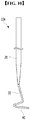
- FIG. 15 is a diagram illustrating a procedure for performing bone reduction surgery using the closed reduction tool 10d according to the fourth embodiment by way of example.
- an operator places the closed reduction tool 10d according to the fourth embodiment in the erected manner onto the incision window 3 between the bone fragments 1. Then, the operator grips the handle 20 and rotates the spiral portion 40 in one direction and inserts the spiral portion 40 into between the bone fragments 1 through the incision window 3.
- the operator lifts the depressed bone fragments 1 while a wide contact face between the spiral portion 40 and bone fragments 1 is maintained.
- the closed reduction tool 10d according to the fourth embodiment lifts the depressed bone fragments 1 in the vertical direction, differently from the conventional manner, such that damage to other surrounding bones is prevented.
- the operator may form the incision window 3 between the bone fragments 1 using a drill (not shown). Then, the operator may perform a reduction operation by inserting the closed reduction tool for the bone fracture having a diameter corresponding to a diameter of the incision window 3 through the incision window 3 and lifting the bone fragments 1.
- FIG. 16 is a diagram illustrating an alternative operation procedure using the closed reduction tool 10d according to the fourth embodiment.
- the operator rotates the spiral portion 40 in an opposite direction to the direction for insertion, as shown in (d) in FIG. 16 .
- the operator tilts the closed reduction tool 10d with respect to the incision window 3 between the bone fragments 1 in the same manner as in the insertion of the closed reduction tool 10d. In this state, the operator lifts the closed reduction tool 10d out of the bone fragments 1 while rotating the spiral portion 40 in an opposite direction to the direction for the insertion.
- FIGS. 11 to 14 show a closed reduction tool for a bone fracture according to a sixth embodiment of the present invention.
- a closed reduction tool 10f according to the sixth embodiment further includes a fixture 50, unlike the first to fifth embodiments described above.
- the fixture 50 includes a pivot joint 51 and a plurality of pivotable legs 61.
- the pivot joint 51 includes a joint body 53 and a sleeve 55 pivotally coupled to the joint body 53, as shown in FIG. 14 .
- the sleeve 55 has a hollow pipe shape with a circular cross section, and the handle 20 is pivotally supported on the sleeve 55 so as to be linearly movable. Further, a pair of guide protrusions 57 are formed on an inner circumference of the sleeve 55. The pair of guide protrusions 57 protrude to a predetermined height along an inserting direction of the handle 20, for example, in a longitudinal direction of the sleeve 55. The pair of guide protrusions 57 are positioned symmetrically on the inner circumference of the sleeve 55.
- the plurality of pivotable legs 61 are provided on an outer surface of the pivot joint 51 to support the pivot joint 51 to be spaced from the bone fragments 1.
- the plurality of pivotable legs 61 are pivotally hinged to the pivot joint 51.
- the fixture is stably mounted on a portion to be operated having a straight shape, or on various portions having concaved or convex curved shapes.
- a pad 63 which is resiliently supported around the bone fragments 1, is mounted on at each distal end of each of the pivotable legs 61.
- the pad 63 is made of rubber or silicon material.
- the closed reduction tool lOe according to the sixth embodiment further includes a lifter 70 for lifting the handle 20 pivotally supported on the fixture 50.
- the lifter 70 includes a threaded portion 71 and a knob 75.
- the threaded portion 71 is positioned on a portion of an outer circumferential surface of the handle 20. That is, in some embodiments, the threaded portion 71 is positioned on the portion of the outer circumferential surface of the handle 20 passing through the pivot joint 51.
- the threaded portion 71 has a pair of guide grooves 73 depressed to a predetermined depth along the longitudinal direction of the handle 20 in correspondence with the pair of guide protrusions 57 of the pivot joint 51.
- Each of the guide protrusions 57 of the pivot joint 51 is movably fitted in each of the guide grooves 73 of the handle 20.
- the knob 75 is screw-coupled to the threaded portion 71 to be sliding on the pivot joint 51.
- a thread of the same size as that of the thread of the threaded portion 71 is formed on an inner circumference of the knob 75.
- the knob 75 vertically moves the handle 20 toward or away from the bone fragments 1 via screw movement between the knob 75 and the threaded portion 71.
- the handle 20 When an operator rotates the knob 75 in one direction or the opposite direction while sliding the knob 75 on the pivot joint 51, the handle 20 does not rotate with respect to the pivot joint 51, but stably and linearly moves up and down because each guide protrusion 57 of the pivot joint 51 is movably fitted into each guide groove 73 of the handle 20.
- FIG. 17 shows a state in which the closed reduction tool lOe according to the sixth embodiment is mounted on a straight shaped fractured piece.
- FIG. 18 shows a state in which the closed reduction tool lOe to the sixth embodiment is mounted on a fractured piece having a curved shape.
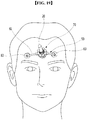
- FIG. 19 is a view showing a state in which the closed reduction tool lOe according to the sixth embodiment is mounted on a face of a subject.
- the spiral portion 40 of the closed reduction tool 10e is inserted through the incision window 3 between the bone fragments 1. Then, the handle 20 is mounted on the fixture 50 so as to penetrate the pivot joint 51. In this connection, an operator places each pivotable leg 61 of the fixture 50 around the bone fragments 1.
- the operator rotates the knob 75 in one direction while sliding the knob 75 on the pivot joint 51, the handle 20 with the threaded portion 71 is raised up from the bone fragments 1.
- the handle 20 rises up, for example, the spiral portion 40 rises up, thereby to lift the depressed bone fragments 1 while the wide contact surface between the depressed bone fragments 1 and the spiral portion 40 is maintained.
- the handle 20 is stably supported by the fixture 50.
- vibrations of the handle 20 and the spiral portion 40 are minimized.
- the bone fragments 1 can be stably reduced or recovered.
- the depressed bone fragments 1 are precisely tuned and lifted for the recovery.
- the closed reduction tool 10e may be used without the lifter 70. That is, after the operator holds the handle 20 and inserts the spiral portion 40 through the incision window 3 between the bone fragments 1, the operator mounts the fixture 50 so that the handle 20 passes through the pivot joint 51. In this connection, each pivotable leg 61 of the fixture 50 is placed around the bone fragments 1.
- the handle 20 While the handle 20 is supported on the pivot joint 51, the operator lifts the handle 20 to be spaced from the bone fragments 1 while the wide contact surface between the spiral portion 40 and the depressed bone fragments 1 is maintained.
- the handle 20 is stably fixed by the fixture 50.
- the tool may be mounted on various body portions and the lifting direction of the handle may vary. When the operator lifts the bone fragments 1, fluctuations of the handle 20 and the spiral portion 40 are minimized, so that the bone fragments 1 are stably reduced or recovered.
- the tool has the spiral portion of a helical shape that is configured to be inserted into a small incision window between depressed bone fragments, and thus simultaneously lift the bone fragments. That is, the tool may be easily inserted and be removed through the small incision window and may reliably restore the depressed bone fragments by lifting the depressed bone fragments.
- the handle is held on the fixture and is lifted.
- the tool may be supported on various body portions and a direction of lifting the tool may be changed. Further, when the operator lifts the bone fragments, the fluctuation of the handle and the spiral portion is minimized, thereby to reduce the bone fragments reliably.
- providing the lifter that lifts the handle pivotably held by the fixture allows the depressed bone fragments to be precisely tuned and lifted by the operator and to be reliably reduced.
Landscapes
- Health & Medical Sciences (AREA)
- Surgery (AREA)
- Life Sciences & Earth Sciences (AREA)
- Medical Informatics (AREA)
- Animal Behavior & Ethology (AREA)
- Engineering & Computer Science (AREA)
- Biomedical Technology (AREA)
- Heart & Thoracic Surgery (AREA)
- Veterinary Medicine (AREA)
- Molecular Biology (AREA)
- Nuclear Medicine, Radiotherapy & Molecular Imaging (AREA)
- General Health & Medical Sciences (AREA)
- Public Health (AREA)
- Orthopedic Medicine & Surgery (AREA)
- Surgical Instruments (AREA)
- Packaging Of Annular Or Rod-Shaped Articles, Wearing Apparel, Cassettes, Or The Like (AREA)
- Workshop Equipment, Work Benches, Supports, Or Storage Means (AREA)
- Devices For Opening Bottles Or Cans (AREA)
Abstract
Description
- Embodiments of the present invention described herein relate to a closed reduction tool for a bone fracture, and more particularly to a closed reduction tool for a bone fracture to restore depressed bone fragments.
- Generally, a plastic surgery is being performed for patients having depressed bone fragments in a facial region due to an external impact.
- Such a surgical operation is performed by inserting a rigid surgical instrument into a region having the depressed fragments optionally by incision thereof, and unfolding or lifting the depressed bone fragments using a principle of lever.
- For example, when the rigid instrument is inserted into between the depressed bone fragments in which in turn are lifted by the instrument, this lifting operation may damage other bones surrounding the region having the depressed fragments.
- Further, there is a problem that when a direction of a force for lifting the bone out is different from a transmission direction of a force from the surgical instrument, that is, both directions of the forces non-coincide with each other, it is difficult to smoothly transmit the lifting force to the damaged bond fragments via the instrument.
- Accordingly, since other bones may be damaged during the surgical procedure, in many cases, a skin is incised to perform a further operation to restore the damaged bone fragments.
- Although a need for a surgical instrument for minimally invasive surgery to minimize scar is increasing, development of such a surgical instrument has not been accomplished as expected.
- When a conventional surgical instrument is used, for example, for treatment of a frontal sinus fracture having many bone fragments, a bone fragment at one side of the leverage is reduced (restored), while a bone fragment at the other side of the leverage area is more dislocated.
- For this reason, there occurs a need for developing a surgical instrument capable of being inserted into a small incision window, and of vertically lifting a bone fragment at one side thereof while not applying force to a bone fragment at the other side thereof, or of lifting a plurality of bone fragments at the same time.
- Embodiments of the present invention are to solve the above-mentioned problem and is to provide a closed reduction tool for a bone fracture that can be easily inserted and removed through a small incision window and can lift a depressed fractured piece stably to restore the same.
- Further, embodiments of the present invention are to provide a closed reduction tool for a bone fracture which may be supported on various portions and may change a direction of lifting thereof, and may restoring a fractured piece stably via minimization of fluctuation of a handle and a spiral portion thereof when an operator lifts the fractured piece.
- Further, embodiments of the present invention are to provide a closed reduction tool for a bone fracture which may finely tune and lift a depressed bone fragments to restore the bone fragments .
- The objective of the present invention can be achieved by, a closed reduction tool for a bone fracture according to an exemplary embodiment. The closed reduction tool includes: a handle to be gripped; a support extending from the handle in a linear manner; and a spiral portion extending from the support in a spiral shape, wherein the spiral portion is configured to be inserted into between depressed bone fragments and lifts the depressed bone fragments.
- In this connection, a winding radius of the spiral portion may be greater than a radius of the handle.
- Further, the spiral portion may be wound in a coplanar manner.
- A distal end of the support may be windingly extended around a central axis of the handle so as to configure a step between the support and the spiral portion, and the distal end may be connected to the spiral portion.
- The spiral portion may be wound into a direction perpendicular to a central axis of the handle.
- The spiral portion may have a size smaller than or equal to a spiral radius.
- The support may extend in an inclined manner with respect to a central axis of the handle.
- The tool may further include a fixture having a pivot joint for pivotally supporting the handle so as to allow linear movement of the handle; and a plurality of pivotable legs coupled to the pivot joint for supporting the pivot joint to be spaced from the bone fragments.
- The tool may further include a lifter for lifting the handle pivotally supported on the fixture.
- The lifter may include a threaded portion partially formed in a circumferential surface of the handle; and a knob screw-coupled to the threaded portion to be sliding on the pivot joint. A screw-movement between the knob and the threaded portion allows the handle to be spaced from the bone fragments.
- The tool may further include a guide groove positioned in the threaded portion, having a predetermined depth and extending along a longitudinal direction of the handle; and a guide protrusion protruding from the pivot joint, having a predetermined height and being movably coupled with the guide groove.
- The plurality of pivotable legs may be pivotally coupled to the pivot joint.
- The tool may further include each pad that is mounted on a respective distal end of a respective pivotable leg, configured to elastically support the respective pivotable leg, and positioned around the bone fragments.
- According to the present invention, the tool has the spiral portion of a helical shape that can be inserted into a small incision window between depressed bone fragments, and thus simultaneously may lift the bone fragments. That is, the tool may be easily inserted and be removed through the small incision window and may reliably restore the depressed bone fragments by lifting the depressed bone fragments.
- Further, the handle is held on the fixture and is lifted. Thus, the tool may be supported on various body portions and a direction of lifting the tool may be changed. Further, when the operator lifts the bone fragments, the fluctuation of the handle and the spiral portion is minimized, thereby to reduce the bone fragments reliably.
- Moreover, providing a lifter that lifting the handle pivotably held by the fixture may allow the depressed pulling to be precisely tuned and lifted by the operator and to be reliably reduced.
-
-
FIG. 1 is a perspective view of a closed reduction tool for a bone fracture according to a first embodiment of the present invention; -
FIG. 2 is a front view of the closed reduction tool shown inFIG. 1 ; -
FIG. 3 is a perspective view of a closed reduction tool for a bone fracture according to a second embodiment of the present invention; -
FIG. 4 is a front view of the closed reduction tool shown inFIG. 3 ; -
FIG. 5 is a perspective view of a closed reduction tool for a bone fracture according to a third embodiment of the present invention; -
FIG. 6 is a front view of the closed reduction tool shown inFIG. 5 ; -
FIG. 7 is a perspective view of a closed reduction tool for a bone fracture according to a fourth embodiment of the present invention; -
FIG. 8 is a front view of the closed reduction tool shown inFIG. 7 , -
FIG. 9 is a perspective view of a closed reduction tool for a bone fracture according to a fifth embodiment of the present invention; -
FIG. 10 is a front view of the closed reduction tool shown inFIG. 9 ; -
FIG. 11 is a perspective view of a closed reduction tool for a bone fracture according to a sixth embodiment of the present invention; -
FIG. 12 is a top perspective view of the closed reduction tool shown inFIG. 11 ; -
FIG. 13 is an exploded perspective view of the closed reduction tool shown inFIG. 11 ; -
FIG. 14 is a perspective view of the pivot joint shown inFIG. 11 ; -
FIG. 15 is a view illustrating a procedure of operation using a closed reduction tool for a bone fracture according to the fourth embodiment of the present invention; -
FIG. 16 is a view illustrating a procedure of another operation using a closed reduction tool for a bone fracture according to the fourth embodiment of the present invention; -
FIG. 17 is a view showing a state in which a closed reduction tool for a bone fracture according to the sixth embodiment of the present invention is mounted on a straight shaped fractured piece; -
FIG. 18 is a view showing a state in which a closed reduction tool for a bone fracture according to the sixth embodiment of the present invention is mounted on a fractured piece having a curved shape; and -
FIG. 19 is a view showing a state in which a closed reduction tool for a bone fracture according to the sixth embodiment of the present invention is mounted on a face. - Hereinafter, preferred embodiments of the present invention will be described in detail with reference to the accompanying drawings. Advantages and features of the present invention, and methods of accomplishing the same, will become apparent with reference to the embodiments described in detail below with reference to the accompanying drawings. However, the present invention is not limited to the embodiments disclosed below, but may be embodied in various forms. These embodiments are provided so that the disclosure of the present invention is complete and that it is believed that the disclosure is intended to be completely understood by those skilled in the art to which the present invention belongs.
- The terminology used herein is for the purpose of describing particular embodiments only and is not intended to be limiting of the present disclosure. As used herein, the singular forms "a" and "an" are intended to include the plural forms as well, unless the context clearly indicates otherwise. It will be further understood that the terms "comprises", "comprising", "includes", and "including" when used in this specification, specify the presence of the stated features, integers, operations, elements, and/or components, but do not preclude the presence or addition of one or more other features, integers, operations, elements, components, and/or portions thereof. As used herein, the term "and/or" includes any and all combinations of one or more of the associated listed items. Unless otherwise defined, all terms including technical and scientific terms used herein have the same meaning as commonly understood by one of ordinary skill in the art to which this present invention belongs. It will be further understood that terms, such as those defined in commonly used dictionaries, should be interpreted as having a meaning that is consistent with their meaning in the context of the relevant art and will not be interpreted in an idealized or overly formal sense unless expressly so defined herein.
- The present invention will now be described in detail with reference to the accompanying drawings.
- Prior to the description, followings should be noted: components having the same configuration between various embodiments may be denoted by the same reference numeral; the component having the same configuration will be first described with reference to the first embodiment, and description thereof will be omitted in remaining embodiments; only components as disclosed in the first embodiment will be described in the remaining embodiments.
- Further, the closed reduction tool for a bone fracture according to the present invention may be applied not only to a facial bone but also to various bone portions of the human body.
-
FIG. 1 andFIG. 2 show a closed reduction tool for a bone fracture according to a first embodiment of the present invention. - As shown in
FIGS. 1 and2 , aclosed reduction tool 10a according to the first embodiment includes ahandle 20, asupport 30, and aspiral portion 40. - The
handle 20 has a cylindrical shape on which an operator is capable of gripping thetool 1 0a. An end portion of thehandle 20 facing thesupport 30 has a tapered shape. Thehandle 20 may has a projection on a surface thereof or has an anti-slip pad made of rubber thereon, to prevent the handle from slipping on the hand of the operator when the operator is inserting or lifting theclosed reduction tool 10a. - The
support 30 has a wire shape having a predetermined length, and extends along a central axis of thehandle 20 and from an end of thehandle 20. - In one example, the
support 30 has astraight portion 33 and a distal end. The distal end of thesupport 30 is helically extending from thestraight portion 33 and around the central axis of thehandle 20 by a helical radius larger than a radius of thehandle 20, thereby to configure a step between thestraight portion 33 and thespiral portion 40. The distal end of thesupport 30 connects to thespiral portion 40. Thus, the distal end of thesupport 30 configures a step between thestraight portion 33 of thesupport 30 and thespiral portion 40. - The
spiral portion 40 has a wire shape and extends in a half-spiral shape. The windingportion 40 extends from thesupport 30. Thespiral portion 40 has a left-oriented spiral shape with a radius greater than the radius of thehandle 20. Further, thespiral portion 40 is wound in a coplanar manner and has a flat shape. - The
closed reduction tool 10a according to the first embodiment is configured to be inserted into an incision window 3 (shown inFIG. 15 ) between depressed bone fragments 1 (shown inFIG. 15 ) in an inclined manner. Theclosed reduction tool 10a according to the first embodiment of this present invention may be useful when there is a sufficient space inside the depressed bone fragments 1. Theclosed reduction tool 10a according to the first embodiment is embodied as a closed reduction tool for a bone fracture with a relatively large helical radius and has a large contact area with the bone after being inserted inside the bone. -
FIG. 3 andFIG. 4 show a closed reduction tool for a bone fracture according to a second embodiment of the present invention. - As shown in
FIGS. 3 and4 , aclosed reduction tool 10b according to the second embodiment differs from that theclosed reduction tool 10a of the first embodiment described above in that thespiral portion 40 extends in a non-coplanar manner, and extends from thesupport 30 in a half-spiral shape around the central axis of thehandle 20. Further, in the second embodiment, thespiral portion 40 extends in an inclined manner with respect to the central axis of thehandle 20, and thespiral portion 40 is wound with a helical radius smaller than that of thespiral portion 40 of the first embodiment. - The
closed reduction tool 10b according to the second embodiment is configured to be inserted into the incision window 3 (shown inFIG. 15 ) between depressed bone fragments 1 (shown inFIG. 15 ) in an erected manner. Theclosed reduction tool 10b according to the second embodiment is useful when there is an in sufficient space inside the depressed bone fragments 1. -
FIG. 5 andFIG. 6 show a closed reduction tool for a bone fracture according to a third embodiment of the present invention. - As shown in
FIGS. 5 and6 , aclosed reduction tool 10c according to the third embodiment differs from theclosed reduction tool 10a of the first embodiment described above in that thespiral portion 40 extends in a non-coplanar manner, and differs from theclosed reduction tool 10b of the second embodiment described above in that the distal end of thesupport 30 extends in a straight manner. Thespiral portion 40 of theclosed reduction tool 10c extends in a half-spiral shape around the central axis of thehandle 20. - The
closed reduction tool 10c according to the third embodiment is useful when a wide tool cannot be inserted into between the bone fragments due to a thickness and a size of the depressed bone fragments 1 (shown inFIG. 15 ). Further, theclosed reduction tool 10c according to the third embodiment is configured to be inserted into between the bone fragments 1 and to be lifted while rotating theclosed reduction tool 10c. -
FIG. 7 andFIG. 8 show a closed reduction tool for a bone fracture according to a fourth embodiment of the present invention. - As shown in
FIGS. 7 and8 , aclosed reduction tool 10d according to the fourth embodiment differs from theclosed reduction tool 10a of the first embodiment described above in that the distal end of thesupport 30 extends in a straight manner. Thespiral portion 40 of theclosed reduction tool 10d extends in a coplanar manner. Thespiral portion 40 of theclosed reduction tool 10d extends in a half-spiral shape around the central axis of thehandle 20. Further, a plane defined by thespiral portion 40 is perpendicular to the central axis of thehandle 20. - As a result, the
closed reduction tool 10d according to the fourth embodiment has no step between thesupport 30 and thespiral portion 40. - The
closed reduction tool 10d according to the fourth embodiment is constructed such that a contact face between thedepressed bone fragments 1 and thespiral portion 40 is at a right angle with a lifting axis, thereby to easily lift the depressed bone fragments 1. -
FIG. 9 andFIG. 10 show a closed reduction tool for a bone fracture according to a fifth embodiment of the present invention. - As shown in
FIGS. 9 and10 , a closed reduction tool lOe according to the fifth embodiment differs from theclosed reduction tool 10c of the third embodiment as described above in that thesupport 30 extends in an inclined with respect to the central axis of thehandle 20. - The
closed reduction tool 10e according to the fifth embodiment is useful when thetool 10e is required to be inclined obliquely to be inserted through theincision window 3 between the depressed bone fragments 1. - Although the
spiral portion 40 of each of the first to fifth embodiments as described above is shown as being formed in a left-oriented spiral shape, the present disclosure is not limited thereto. Thespiral portion 40 may be formed in a right-oriented spiral shape. - One of the closed reduction tools according to the first to fifth embodiments having various
spiral portions 40 according to the above defined configuration may be selected based on a size and position of the bone fragments 1 and then may be inserted through theincision window 3 between the bone fragments 1. Then, the operator is able to lift the bone fragments 1 concurrently to perform the reduction operation of the bone. -
FIG. 15 is a diagram illustrating a procedure for performing bone reduction surgery using theclosed reduction tool 10d according to the fourth embodiment by way of example. - Referring to the procedure of the operation with reference to
FIG. 15 , as shown in (a) inFIG. 15 , an operator places theclosed reduction tool 10d according to the fourth embodiment in the erected manner onto theincision window 3 between the bone fragments 1. Then, the operator grips thehandle 20 and rotates thespiral portion 40 in one direction and inserts thespiral portion 40 into between the bone fragments 1 through theincision window 3. - Then, as shown in (b) in
FIG. 15 , the operator lifts thedepressed bone fragments 1 while a wide contact face between thespiral portion 40 andbone fragments 1 is maintained. In this connection, theclosed reduction tool 10d according to the fourth embodiment lifts thedepressed bone fragments 1 in the vertical direction, differently from the conventional manner, such that damage to other surrounding bones is prevented. - Then, when the bone fragments 1 is reduced or recovered, as shown in (c) in
FIG. 15 , the operator lifts theclosed reduction tool 10d according to the fourth embodiment from the bone fragments 1 while the operator rotates thespiral portion 40 in a direction opposite to the direction for insertion. This completes the reduction of the bone fragments 1. - In this regard, when the
incision window 3 is not formed between the bone fragments 1, the operator may form theincision window 3 between the bone fragments 1 using a drill (not shown). Then, the operator may perform a reduction operation by inserting the closed reduction tool for the bone fracture having a diameter corresponding to a diameter of theincision window 3 through theincision window 3 and lifting the bone fragments 1. -
FIG. 16 is a diagram illustrating an alternative operation procedure using theclosed reduction tool 10d according to the fourth embodiment. - Referring briefly to the procedure of the operation with reference to
FIG. 16 , as shown in (a) inFIG. 16 , the operator tilts theclosed reduction tool 10d according to the fourth embodiment with respect to theincision window 3 between the bone fragments 1. Then, as shown in (b) inFIG. 16 , the operator grasps thehandle 20 of theclosed reduction tool 10d, rotates thespiral portion 40 thereof in one direction to insert thespiral portion 40 through theincision window 3 into between the bone fragments 1. - Then, as shown in (c) in
FIG. 16 , in a state where thespiral portion 40 of theclosed reduction tool 10d is inserted into between the bone fragments 1, the operator orients theclosed reduction tool 10d in a perpendicular direction to theincision window 3 between the bone fragments 1. Then, the operator lifts thedepressed bone fragments 1 while the wide contact surface between the windingportion 40 and the depressed bone fragments 1 is maintained. In this connection, thedepressed bone fragments 1 are lifted in the vertical direction to prevent the damage to other surrounding bones. - Then, when the bone fragments 1 are reduced or recovered, the operator rotates the
spiral portion 40 in an opposite direction to the direction for insertion, as shown in (d) inFIG. 16 . As shown in (e) inFIG. 16 , the operator tilts theclosed reduction tool 10d with respect to theincision window 3 between the bone fragments 1 in the same manner as in the insertion of theclosed reduction tool 10d. In this state, the operator lifts theclosed reduction tool 10d out of the bone fragments 1 while rotating thespiral portion 40 in an opposite direction to the direction for the insertion. - In this way, the reduction of the bone fragments 1 is completed.
-
FIGS. 11 to 14 show a closed reduction tool for a bone fracture according to a sixth embodiment of the present invention. - A
closed reduction tool 10f according to the sixth embodiment further includes afixture 50, unlike the first to fifth embodiments described above. - The
fixture 50 includes a pivot joint 51 and a plurality ofpivotable legs 61. - The pivot joint 51 includes a
joint body 53 and asleeve 55 pivotally coupled to thejoint body 53, as shown inFIG. 14 . - The
sleeve 55 has a hollow pipe shape with a circular cross section, and thehandle 20 is pivotally supported on thesleeve 55 so as to be linearly movable. Further, a pair ofguide protrusions 57 are formed on an inner circumference of thesleeve 55. The pair ofguide protrusions 57 protrude to a predetermined height along an inserting direction of thehandle 20, for example, in a longitudinal direction of thesleeve 55. The pair ofguide protrusions 57 are positioned symmetrically on the inner circumference of thesleeve 55. - The plurality of
pivotable legs 61 are provided on an outer surface of the pivot joint 51 to support the pivot joint 51 to be spaced from the bone fragments 1. - Further, the plurality of
pivotable legs 61 are pivotally hinged to the pivot joint 51. As a result, the fixture is stably mounted on a portion to be operated having a straight shape, or on various portions having concaved or convex curved shapes. - A
pad 63, which is resiliently supported around the bone fragments 1, is mounted on at each distal end of each of thepivotable legs 61. In some embodiments, thepad 63 is made of rubber or silicon material. - Further, the closed reduction tool lOe according to the sixth embodiment further includes a
lifter 70 for lifting thehandle 20 pivotally supported on thefixture 50. - In some embodiments, the
lifter 70 includes a threadedportion 71 and aknob 75. - In some embodiments, the threaded
portion 71 is positioned on a portion of an outer circumferential surface of thehandle 20. That is, in some embodiments, the threadedportion 71 is positioned on the portion of the outer circumferential surface of thehandle 20 passing through the pivot joint 51. The threadedportion 71 has a pair ofguide grooves 73 depressed to a predetermined depth along the longitudinal direction of thehandle 20 in correspondence with the pair ofguide protrusions 57 of the pivot joint 51. Each of theguide protrusions 57 of the pivot joint 51 is movably fitted in each of theguide grooves 73 of thehandle 20. - The
knob 75 is screw-coupled to the threadedportion 71 to be sliding on the pivot joint 51. In some embodiments, a thread of the same size as that of the thread of the threadedportion 71 is formed on an inner circumference of theknob 75. - According to these features, in some embodiments, the
knob 75 vertically moves thehandle 20 toward or away from the bone fragments 1 via screw movement between theknob 75 and the threadedportion 71. - That is, when the
knob 75 is rotated in one direction while theknob 75 is sliding on the pivot joint 51, thehandle 20 having the threadedportion 71 is raised. Conversely, when theknob 75 is rotated in an opposite direction while theknob 75 is sliding on the pivot joint 51, thehandle 20 having the threadedportion 71 is lowered. - When an operator rotates the
knob 75 in one direction or the opposite direction while sliding theknob 75 on the pivot joint 51, thehandle 20 does not rotate with respect to the pivot joint 51, but stably and linearly moves up and down because eachguide protrusion 57 of the pivot joint 51 is movably fitted into eachguide groove 73 of thehandle 20. -
FIG. 17 shows a state in which the closed reduction tool lOe according to the sixth embodiment is mounted on a straight shaped fractured piece. - Further,
FIG. 18 shows a state in which the closed reduction tool lOe to the sixth embodiment is mounted on a fractured piece having a curved shape. - Furthermore,
FIG. 19 is a view showing a state in which the closed reduction tool lOe according to the sixth embodiment is mounted on a face of a subject. - Using the above configurations, the
spiral portion 40 of theclosed reduction tool 10e according to the sixth embodiment is inserted through theincision window 3 between the bone fragments 1. Then, thehandle 20 is mounted on thefixture 50 so as to penetrate the pivot joint 51. In this connection, an operator places eachpivotable leg 61 of thefixture 50 around the bone fragments 1. - While the
handle 20 is supported on the pivot joint 51, the operator screws theknob 75 to the threadedportion 71 of thehandle 20. - Then, the operator rotates the
knob 75 in one direction while sliding theknob 75 on the pivot joint 51, thehandle 20 with the threadedportion 71 is raised up from the bone fragments 1. - As the
knob 75 rotates, thehandle 20 rises up, for example, thespiral portion 40 rises up, thereby to lift thedepressed bone fragments 1 while the wide contact surface between thedepressed bone fragments 1 and thespiral portion 40 is maintained. - In this connection, the
handle 20 is stably supported by thefixture 50. Thus, when the operator lifts the bone fragments 1, vibrations of thehandle 20 and thespiral portion 40 are minimized. Thus, the bone fragments 1 can be stably reduced or recovered. Further, as an upward movement of thespiral portion 40 by thelifter 70 is finely tuned, thedepressed bone fragments 1 are precisely tuned and lifted for the recovery. - In this connection, the
closed reduction tool 10e according to the sixth embodiment may be used without thelifter 70. That is, after the operator holds thehandle 20 and inserts thespiral portion 40 through theincision window 3 between the bone fragments 1, the operator mounts thefixture 50 so that thehandle 20 passes through the pivot joint 51. In this connection, eachpivotable leg 61 of thefixture 50 is placed around the bone fragments 1. - While the
handle 20 is supported on the pivot joint 51, the operator lifts thehandle 20 to be spaced from the bone fragments 1 while the wide contact surface between thespiral portion 40 and the depressed bone fragments 1 is maintained. In this connection, thehandle 20 is stably fixed by thefixture 50. Thus, the tool may be mounted on various body portions and the lifting direction of the handle may vary. When the operator lifts the bone fragments 1, fluctuations of thehandle 20 and thespiral portion 40 are minimized, so that the bone fragments 1 are stably reduced or recovered. - According to the present disclosure, the tool has the spiral portion of a helical shape that is configured to be inserted into a small incision window between depressed bone fragments, and thus simultaneously lift the bone fragments. That is, the tool may be easily inserted and be removed through the small incision window and may reliably restore the depressed bone fragments by lifting the depressed bone fragments.
- Further, the handle is held on the fixture and is lifted. Thus, the tool may be supported on various body portions and a direction of lifting the tool may be changed. Further, when the operator lifts the bone fragments, the fluctuation of the handle and the spiral portion is minimized, thereby to reduce the bone fragments reliably.
- Moreover, providing the lifter that lifts the handle pivotably held by the fixture allows the depressed bone fragments to be precisely tuned and lifted by the operator and to be reliably reduced.
- While the present invention has been described with reference to exemplary embodiments, it will be apparent to those skilled in the art that various changes and modifications may be made without departing from the spirit and scope of the present invention. Therefore, it should be understood that the above embodiments are not limiting, but illustrative.
Claims (13)
- A closed reduction tool for a bone fracture, the tool comprising:a handle to be gripped;a support extending from the handle in a linear manner; anda spiral portion extending from the support in a spiral shape, wherein the spiral portion is configured to be inserted into between depressed bone fragments and lift the depressed bone fragments.
- The closed reduction tool of claim 1, wherein a winding radius of the spiral portion is greater than a radius of the handle.
- The closed reduction tool of claim 1, wherein the spiral portion is wound in a coplanar manner.
- The closed reduction tool of claim 1, wherein a distal end of the support is windingly extended around a central axis of the handle so as to configure a step between the support and the spiral portion, wherein the distal end is connected to the spiral portion.
- The closed reduction tool of claim 1, wherein the spiral portion is wound into a direction perpendicular to a central axis of the handle.
- The closed reduction tool of claim 1, wherein the spiral portion has a size smaller than or equal to a spiral radius.
- The closed reduction tool of claim 1, wherein the support extends in an inclined manner with respect to a central axis of the handle.
- The closed reduction tool of claim 1, further comprising:
a fixture that comprises:a pivot joint configured to pivotally support the handle so as to allow a linear movement of the handle; anda plurality of pivotable legs coupled to the pivot joint, and configured to support the pivot joint to be spaced from the bone fragments. - The closed reduction tool of claim 1, further comprising:
a lifter configured to lift the handle that is pivotally supported on the fixture. - The closed reduction tool of claim 9, wherein the lifter comprises:a threaded portion positioned on a portion of a circumferential surface of the handle; anda knob screw-coupled to the threaded portion, and configured to be sliding on the pivot joint,wherein a screw-movement between the knob and the threaded portion allows the handle to be spaced from the bone fragments.
- The closed reduction tool of claim 10, further comprising:a guide groove positioned in the threaded portion, having a predetermined depth, and extending along a longitudinal direction of the handle; anda guide protrusion protruding from the pivot joint, having a predetermined height, and being movably coupled with the guide groove.
- The closed reduction tool of claim 8, wherein the plurality of pivotable legs are pivotally coupled to the pivot joint.
- The closed reduction tool of claim 8, further comprising:
each pad that is mounted on a respective distal end of a respective pivotable leg, configured to elastically support the respective pivotable leg, and positioned around the bone fragments.
Applications Claiming Priority (2)
| Application Number | Priority Date | Filing Date | Title |
|---|---|---|---|
| KR1020160159135A KR101958427B1 (en) | 2016-11-28 | 2016-11-28 | Closed reduction tool for bone fracture |
| PCT/KR2017/012980 WO2018097537A2 (en) | 2016-11-28 | 2017-11-16 | Tool for closed reduction of fracture |
Publications (3)
| Publication Number | Publication Date |
|---|---|
| EP3545884A2 true EP3545884A2 (en) | 2019-10-02 |
| EP3545884A4 EP3545884A4 (en) | 2019-12-18 |
| EP3545884B1 EP3545884B1 (en) | 2020-10-28 |
Family
ID=62195210
Family Applications (1)
| Application Number | Title | Priority Date | Filing Date |
|---|---|---|---|
| EP17874299.5A Active EP3545884B1 (en) | 2016-11-28 | 2017-11-16 | Tool for closed reduction of fracture |
Country Status (4)
| Country | Link |
|---|---|
| US (1) | US11291475B2 (en) |
| EP (1) | EP3545884B1 (en) |
| KR (1) | KR101958427B1 (en) |
| WO (1) | WO2018097537A2 (en) |
Cited By (1)
| Publication number | Priority date | Publication date | Assignee | Title |
|---|---|---|---|---|
| EP3610798A4 (en) * | 2017-04-10 | 2020-05-13 | The Asan Foundation | ORTHOPEDIC FRACTURE REDUCTION DEVICE |
Family Cites Families (15)
| Publication number | Priority date | Publication date | Assignee | Title |
|---|---|---|---|---|
| GB1281863A (en) * | 1970-01-27 | 1972-07-19 | Alfred Beck | Improvements relating to surgical implements |
| US4265231A (en) * | 1979-04-30 | 1981-05-05 | Scheller Jr Arnold D | Curved drill attachment for bone drilling uses |
| US5662683A (en) * | 1995-08-22 | 1997-09-02 | Ortho Helix Limited | Open helical organic tissue anchor and method of facilitating healing |
| US6692502B1 (en) * | 1996-06-24 | 2004-02-17 | Janos Paul Ertl | Process and instrumentation for arthroscopic reduction of central and peripheral depression fractures |
| CN2286620Y (en) | 1996-09-23 | 1998-07-29 | 段华汛 | Resetting device for depressed fracture of cranial bone |
| US6544265B2 (en) * | 2000-11-08 | 2003-04-08 | The Cleveland Clinic Foundation | Apparatus for implantation into bone related applications |
| US7357773B2 (en) * | 2002-03-07 | 2008-04-15 | Ams Research Corporation | Handle and surgical article |
| KR100536168B1 (en) | 2003-10-02 | 2005-12-12 | 유앤아이 주식회사 | an adjusting instruments for a bone fixator |
| CN2652342Y (en) | 2003-11-08 | 2004-11-03 | 戢翰升 | Suspending type reposition device for depressed cranial fracture |
| WO2008033950A2 (en) * | 2006-09-13 | 2008-03-20 | C. R. Bard, Inc. | Urethral support system |
| US20110166660A1 (en) * | 2008-09-02 | 2011-07-07 | Synthes Usa, Llc | Implant with spiral anchor |
| US9254159B2 (en) * | 2009-09-04 | 2016-02-09 | Empire Technology Development Llc | Medical instruments for diaplasis |
| US20110106186A1 (en) * | 2009-11-02 | 2011-05-05 | Nikolaj Wolfson | Bone fragment extraction |
| US20110190764A1 (en) * | 2010-01-29 | 2011-08-04 | Ethicon Endo-Surgery, Inc. | Surgical instrument comprising an electrode |
| CN103271758B (en) * | 2013-05-22 | 2015-08-05 | 苏州爱得科技发展有限公司 | Wicresoft's positor |
-
2016
- 2016-11-28 KR KR1020160159135A patent/KR101958427B1/en active Active
-
2017
- 2017-11-16 WO PCT/KR2017/012980 patent/WO2018097537A2/en not_active Ceased
- 2017-11-16 EP EP17874299.5A patent/EP3545884B1/en active Active
-
2019
- 2019-05-28 US US16/423,943 patent/US11291475B2/en active Active
Cited By (2)
| Publication number | Priority date | Publication date | Assignee | Title |
|---|---|---|---|---|
| EP3610798A4 (en) * | 2017-04-10 | 2020-05-13 | The Asan Foundation | ORTHOPEDIC FRACTURE REDUCTION DEVICE |
| US11583264B2 (en) | 2017-04-10 | 2023-02-21 | The Asan Foundation | Apparatus for closed reduction of bone fracture |
Also Published As
| Publication number | Publication date |
|---|---|
| KR101958427B1 (en) | 2019-03-14 |
| EP3545884B1 (en) | 2020-10-28 |
| WO2018097537A2 (en) | 2018-05-31 |
| EP3545884A4 (en) | 2019-12-18 |
| KR20180060073A (en) | 2018-06-07 |
| US20190274732A1 (en) | 2019-09-12 |
| US11291475B2 (en) | 2022-04-05 |
| WO2018097537A3 (en) | 2018-08-09 |
Similar Documents
| Publication | Publication Date | Title |
|---|---|---|
| JP6946493B2 (en) | Separable guide device for anatomical implants | |
| US20230064691A1 (en) | Chevron osteotomy tools and methods | |
| US10159480B2 (en) | Surgical jig assembly for use in the manipulation and fixation of bony structures | |
| US9931145B2 (en) | Flexible bone screw | |
| US20160106480A1 (en) | Extension piece at screw end of pedicle screw, dilator and push rod reset lever | |
| US20130178860A1 (en) | Soft tissue protector and drill guide for an implantation kit | |
| CN101938948A (en) | Pelvic Cable Solutions | |
| EP2661235B1 (en) | Cannulated guide tools | |
| US11291475B2 (en) | Tool for closed reduction of fracture | |
| JP2016530938A (en) | Surgical instrument for manipulating, positioning and securing a surgical rod relative to an implant | |
| KR101434333B1 (en) | Rod reducer for minimally invasive surgery system | |
| US9913670B2 (en) | Rod inserter for fixing of pedicle screw, screw holder with joint for minimal invasive surgery, screw reducer for minimal invasive surgery and apparatus for minimal invasive surgery using these devices | |
| US20190083147A1 (en) | Instrument assembly for use with an expandable pedicle screw | |
| US11583264B2 (en) | Apparatus for closed reduction of bone fracture | |
| US20180271573A1 (en) | Devices and methods for repairing bone fractures | |
| CN104665902A (en) | Guide fixing device for reduction of fracture | |
| EP2700372B1 (en) | Bone screw and washer insertion tool | |
| KR20190040942A (en) | Closed reduction tool for bone fracture | |
| CN219021491U (en) | Patella tunnel opening and titanium cable implantation instrument | |
| CN112890941B (en) | A medical rapid reduction and internal fixation system for proximal humeral fractures | |
| JP7695717B2 (en) | Surgical instruments, medical instrument sets, and transplantation methods | |
| CN116782855A (en) | Improvements in and related to surgical instruments, systems and methods | |
| KR101464617B1 (en) | Compression-distraction tool for minimally invasive surgery system | |
| US20160287280A1 (en) | Peritoneal Peeling Surgical Instrument | |
| JP2008093055A (en) | Guide pin guiding tool |
Legal Events
| Date | Code | Title | Description |
|---|---|---|---|
| STAA | Information on the status of an ep patent application or granted ep patent |
Free format text: STATUS: THE INTERNATIONAL PUBLICATION HAS BEEN MADE |
|
| PUAI | Public reference made under article 153(3) epc to a published international application that has entered the european phase |
Free format text: ORIGINAL CODE: 0009012 |
|
| STAA | Information on the status of an ep patent application or granted ep patent |
Free format text: STATUS: REQUEST FOR EXAMINATION WAS MADE |
|
| 17P | Request for examination filed |
Effective date: 20190625 |
|
| AK | Designated contracting states |
Kind code of ref document: A2 Designated state(s): AL AT BE BG CH CY CZ DE DK EE ES FI FR GB GR HR HU IE IS IT LI LT LU LV MC MK MT NL NO PL PT RO RS SE SI SK SM TR |
|
| AX | Request for extension of the european patent |
Extension state: BA ME |
|
| A4 | Supplementary search report drawn up and despatched |
Effective date: 20191120 |
|
| RIC1 | Information provided on ipc code assigned before grant |
Ipc: A61B 17/88 20060101AFI20191114BHEP |
|
| DAV | Request for validation of the european patent (deleted) | ||
| DAX | Request for extension of the european patent (deleted) | ||
| REG | Reference to a national code |
Ref country code: DE Ref legal event code: R079 Ref document number: 602017026579 Country of ref document: DE Free format text: PREVIOUS MAIN CLASS: A61B0017560000 Ipc: A61B0017880000 |
|
| GRAP | Despatch of communication of intention to grant a patent |
Free format text: ORIGINAL CODE: EPIDOSNIGR1 |
|
| STAA | Information on the status of an ep patent application or granted ep patent |
Free format text: STATUS: GRANT OF PATENT IS INTENDED |
|
| RIC1 | Information provided on ipc code assigned before grant |
Ipc: A61B 17/88 20060101AFI20200526BHEP |
|
| INTG | Intention to grant announced |
Effective date: 20200616 |
|
| GRAS | Grant fee paid |
Free format text: ORIGINAL CODE: EPIDOSNIGR3 |
|
| GRAA | (expected) grant |
Free format text: ORIGINAL CODE: 0009210 |
|
| STAA | Information on the status of an ep patent application or granted ep patent |
Free format text: STATUS: THE PATENT HAS BEEN GRANTED |
|
| AK | Designated contracting states |
Kind code of ref document: B1 Designated state(s): AL AT BE BG CH CY CZ DE DK EE ES FI FR GB GR HR HU IE IS IT LI LT LU LV MC MK MT NL NO PL PT RO RS SE SI SK SM TR |
|
| REG | Reference to a national code |
Ref country code: GB Ref legal event code: FG4D |
|
| REG | Reference to a national code |
Ref country code: CH Ref legal event code: EP |
|
| REG | Reference to a national code |
Ref country code: AT Ref legal event code: REF Ref document number: 1327398 Country of ref document: AT Kind code of ref document: T Effective date: 20201115 |
|
| REG | Reference to a national code |
Ref country code: DE Ref legal event code: R096 Ref document number: 602017026579 Country of ref document: DE |
|
| REG | Reference to a national code |
Ref country code: IE Ref legal event code: FG4D |
|
| REG | Reference to a national code |
Ref country code: AT Ref legal event code: MK05 Ref document number: 1327398 Country of ref document: AT Kind code of ref document: T Effective date: 20201028 |
|
| REG | Reference to a national code |
Ref country code: NL Ref legal event code: MP Effective date: 20201028 |
|
| PG25 | Lapsed in a contracting state [announced via postgrant information from national office to epo] |
Ref country code: GR Free format text: LAPSE BECAUSE OF FAILURE TO SUBMIT A TRANSLATION OF THE DESCRIPTION OR TO PAY THE FEE WITHIN THE PRESCRIBED TIME-LIMIT Effective date: 20210129 Ref country code: NO Free format text: LAPSE BECAUSE OF FAILURE TO SUBMIT A TRANSLATION OF THE DESCRIPTION OR TO PAY THE FEE WITHIN THE PRESCRIBED TIME-LIMIT Effective date: 20210128 Ref country code: FI Free format text: LAPSE BECAUSE OF FAILURE TO SUBMIT A TRANSLATION OF THE DESCRIPTION OR TO PAY THE FEE WITHIN THE PRESCRIBED TIME-LIMIT Effective date: 20201028 Ref country code: RS Free format text: LAPSE BECAUSE OF FAILURE TO SUBMIT A TRANSLATION OF THE DESCRIPTION OR TO PAY THE FEE WITHIN THE PRESCRIBED TIME-LIMIT Effective date: 20201028 Ref country code: PT Free format text: LAPSE BECAUSE OF FAILURE TO SUBMIT A TRANSLATION OF THE DESCRIPTION OR TO PAY THE FEE WITHIN THE PRESCRIBED TIME-LIMIT Effective date: 20210301 |
|
| REG | Reference to a national code |
Ref country code: LT Ref legal event code: MG4D |
|
| PG25 | Lapsed in a contracting state [announced via postgrant information from national office to epo] |
Ref country code: SE Free format text: LAPSE BECAUSE OF FAILURE TO SUBMIT A TRANSLATION OF THE DESCRIPTION OR TO PAY THE FEE WITHIN THE PRESCRIBED TIME-LIMIT Effective date: 20201028 Ref country code: PL Free format text: LAPSE BECAUSE OF FAILURE TO SUBMIT A TRANSLATION OF THE DESCRIPTION OR TO PAY THE FEE WITHIN THE PRESCRIBED TIME-LIMIT Effective date: 20201028 Ref country code: LV Free format text: LAPSE BECAUSE OF FAILURE TO SUBMIT A TRANSLATION OF THE DESCRIPTION OR TO PAY THE FEE WITHIN THE PRESCRIBED TIME-LIMIT Effective date: 20201028 Ref country code: IS Free format text: LAPSE BECAUSE OF FAILURE TO SUBMIT A TRANSLATION OF THE DESCRIPTION OR TO PAY THE FEE WITHIN THE PRESCRIBED TIME-LIMIT Effective date: 20210228 Ref country code: BG Free format text: LAPSE BECAUSE OF FAILURE TO SUBMIT A TRANSLATION OF THE DESCRIPTION OR TO PAY THE FEE WITHIN THE PRESCRIBED TIME-LIMIT Effective date: 20210128 Ref country code: ES Free format text: LAPSE BECAUSE OF FAILURE TO SUBMIT A TRANSLATION OF THE DESCRIPTION OR TO PAY THE FEE WITHIN THE PRESCRIBED TIME-LIMIT Effective date: 20201028 Ref country code: AT Free format text: LAPSE BECAUSE OF FAILURE TO SUBMIT A TRANSLATION OF THE DESCRIPTION OR TO PAY THE FEE WITHIN THE PRESCRIBED TIME-LIMIT Effective date: 20201028 |
|
| PG25 | Lapsed in a contracting state [announced via postgrant information from national office to epo] |
Ref country code: HR Free format text: LAPSE BECAUSE OF FAILURE TO SUBMIT A TRANSLATION OF THE DESCRIPTION OR TO PAY THE FEE WITHIN THE PRESCRIBED TIME-LIMIT Effective date: 20201028 Ref country code: NL Free format text: LAPSE BECAUSE OF FAILURE TO SUBMIT A TRANSLATION OF THE DESCRIPTION OR TO PAY THE FEE WITHIN THE PRESCRIBED TIME-LIMIT Effective date: 20201028 |
|
| REG | Reference to a national code |
Ref country code: CH Ref legal event code: PL |
|
| REG | Reference to a national code |
Ref country code: DE Ref legal event code: R097 Ref document number: 602017026579 Country of ref document: DE |
|
| PG25 | Lapsed in a contracting state [announced via postgrant information from national office to epo] |
Ref country code: RO Free format text: LAPSE BECAUSE OF FAILURE TO SUBMIT A TRANSLATION OF THE DESCRIPTION OR TO PAY THE FEE WITHIN THE PRESCRIBED TIME-LIMIT Effective date: 20201028 Ref country code: SK Free format text: LAPSE BECAUSE OF FAILURE TO SUBMIT A TRANSLATION OF THE DESCRIPTION OR TO PAY THE FEE WITHIN THE PRESCRIBED TIME-LIMIT Effective date: 20201028 Ref country code: SM Free format text: LAPSE BECAUSE OF FAILURE TO SUBMIT A TRANSLATION OF THE DESCRIPTION OR TO PAY THE FEE WITHIN THE PRESCRIBED TIME-LIMIT Effective date: 20201028 Ref country code: EE Free format text: LAPSE BECAUSE OF FAILURE TO SUBMIT A TRANSLATION OF THE DESCRIPTION OR TO PAY THE FEE WITHIN THE PRESCRIBED TIME-LIMIT Effective date: 20201028 Ref country code: CZ Free format text: LAPSE BECAUSE OF FAILURE TO SUBMIT A TRANSLATION OF THE DESCRIPTION OR TO PAY THE FEE WITHIN THE PRESCRIBED TIME-LIMIT Effective date: 20201028 Ref country code: LU Free format text: LAPSE BECAUSE OF NON-PAYMENT OF DUE FEES Effective date: 20201116 Ref country code: MC Free format text: LAPSE BECAUSE OF FAILURE TO SUBMIT A TRANSLATION OF THE DESCRIPTION OR TO PAY THE FEE WITHIN THE PRESCRIBED TIME-LIMIT Effective date: 20201028 Ref country code: LT Free format text: LAPSE BECAUSE OF FAILURE TO SUBMIT A TRANSLATION OF THE DESCRIPTION OR TO PAY THE FEE WITHIN THE PRESCRIBED TIME-LIMIT Effective date: 20201028 |
|
| REG | Reference to a national code |
Ref country code: BE Ref legal event code: MM Effective date: 20201130 |
|
| PG25 | Lapsed in a contracting state [announced via postgrant information from national office to epo] |
Ref country code: DK Free format text: LAPSE BECAUSE OF FAILURE TO SUBMIT A TRANSLATION OF THE DESCRIPTION OR TO PAY THE FEE WITHIN THE PRESCRIBED TIME-LIMIT Effective date: 20201028 Ref country code: LI Free format text: LAPSE BECAUSE OF NON-PAYMENT OF DUE FEES Effective date: 20201130 Ref country code: CH Free format text: LAPSE BECAUSE OF NON-PAYMENT OF DUE FEES Effective date: 20201130 |
|
| PLBE | No opposition filed within time limit |
Free format text: ORIGINAL CODE: 0009261 |
|
| STAA | Information on the status of an ep patent application or granted ep patent |
Free format text: STATUS: NO OPPOSITION FILED WITHIN TIME LIMIT |
|
| 26N | No opposition filed |
Effective date: 20210729 |
|
| PG25 | Lapsed in a contracting state [announced via postgrant information from national office to epo] |
Ref country code: IE Free format text: LAPSE BECAUSE OF NON-PAYMENT OF DUE FEES Effective date: 20201116 Ref country code: FR Free format text: LAPSE BECAUSE OF NON-PAYMENT OF DUE FEES Effective date: 20201228 Ref country code: AL Free format text: LAPSE BECAUSE OF FAILURE TO SUBMIT A TRANSLATION OF THE DESCRIPTION OR TO PAY THE FEE WITHIN THE PRESCRIBED TIME-LIMIT Effective date: 20201028 Ref country code: IT Free format text: LAPSE BECAUSE OF FAILURE TO SUBMIT A TRANSLATION OF THE DESCRIPTION OR TO PAY THE FEE WITHIN THE PRESCRIBED TIME-LIMIT Effective date: 20201028 |
|
| PG25 | Lapsed in a contracting state [announced via postgrant information from national office to epo] |
Ref country code: SI Free format text: LAPSE BECAUSE OF FAILURE TO SUBMIT A TRANSLATION OF THE DESCRIPTION OR TO PAY THE FEE WITHIN THE PRESCRIBED TIME-LIMIT Effective date: 20201028 |
|
| PG25 | Lapsed in a contracting state [announced via postgrant information from national office to epo] |
Ref country code: IS Free format text: LAPSE BECAUSE OF FAILURE TO SUBMIT A TRANSLATION OF THE DESCRIPTION OR TO PAY THE FEE WITHIN THE PRESCRIBED TIME-LIMIT Effective date: 20210228 Ref country code: TR Free format text: LAPSE BECAUSE OF FAILURE TO SUBMIT A TRANSLATION OF THE DESCRIPTION OR TO PAY THE FEE WITHIN THE PRESCRIBED TIME-LIMIT Effective date: 20201028 Ref country code: MT Free format text: LAPSE BECAUSE OF FAILURE TO SUBMIT A TRANSLATION OF THE DESCRIPTION OR TO PAY THE FEE WITHIN THE PRESCRIBED TIME-LIMIT Effective date: 20201028 Ref country code: CY Free format text: LAPSE BECAUSE OF FAILURE TO SUBMIT A TRANSLATION OF THE DESCRIPTION OR TO PAY THE FEE WITHIN THE PRESCRIBED TIME-LIMIT Effective date: 20201028 |
|
| PG25 | Lapsed in a contracting state [announced via postgrant information from national office to epo] |
Ref country code: MK Free format text: LAPSE BECAUSE OF FAILURE TO SUBMIT A TRANSLATION OF THE DESCRIPTION OR TO PAY THE FEE WITHIN THE PRESCRIBED TIME-LIMIT Effective date: 20201028 |
|
| GBPC | Gb: european patent ceased through non-payment of renewal fee |
Effective date: 20211116 |
|
| PG25 | Lapsed in a contracting state [announced via postgrant information from national office to epo] |
Ref country code: BE Free format text: LAPSE BECAUSE OF NON-PAYMENT OF DUE FEES Effective date: 20201130 |
|
| PG25 | Lapsed in a contracting state [announced via postgrant information from national office to epo] |
Ref country code: GB Free format text: LAPSE BECAUSE OF NON-PAYMENT OF DUE FEES Effective date: 20211116 |
|
| PGFP | Annual fee paid to national office [announced via postgrant information from national office to epo] |
Ref country code: DE Payment date: 20250922 Year of fee payment: 9 |