EP3545467B1 - Procédé et système pour l'évaluation de la qualité d'images de visage - Google Patents
Procédé et système pour l'évaluation de la qualité d'images de visage Download PDFInfo
- Publication number
- EP3545467B1 EP3545467B1 EP17888585.1A EP17888585A EP3545467B1 EP 3545467 B1 EP3545467 B1 EP 3545467B1 EP 17888585 A EP17888585 A EP 17888585A EP 3545467 B1 EP3545467 B1 EP 3545467B1
- Authority
- EP
- European Patent Office
- Prior art keywords
- image
- face
- parameter
- value
- quality
- Prior art date
- Legal status (The legal status is an assumption and is not a legal conclusion. Google has not performed a legal analysis and makes no representation as to the accuracy of the status listed.)
- Active
Links
Images


Classifications
-
- G—PHYSICS
- G06—COMPUTING OR CALCULATING; COUNTING
- G06V—IMAGE OR VIDEO RECOGNITION OR UNDERSTANDING
- G06V40/00—Recognition of biometric, human-related or animal-related patterns in image or video data
- G06V40/10—Human or animal bodies, e.g. vehicle occupants or pedestrians; Body parts, e.g. hands
- G06V40/16—Human faces, e.g. facial parts, sketches or expressions
- G06V40/161—Detection; Localisation; Normalisation
-
- G—PHYSICS
- G06—COMPUTING OR CALCULATING; COUNTING
- G06V—IMAGE OR VIDEO RECOGNITION OR UNDERSTANDING
- G06V10/00—Arrangements for image or video recognition or understanding
- G06V10/40—Extraction of image or video features
- G06V10/42—Global feature extraction by analysis of the whole pattern, e.g. using frequency domain transformations or autocorrelation
- G06V10/431—Frequency domain transformation; Autocorrelation
-
- G—PHYSICS
- G06—COMPUTING OR CALCULATING; COUNTING
- G06V—IMAGE OR VIDEO RECOGNITION OR UNDERSTANDING
- G06V10/00—Arrangements for image or video recognition or understanding
- G06V10/98—Detection or correction of errors, e.g. by rescanning the pattern or by human intervention; Evaluation of the quality of the acquired patterns
- G06V10/993—Evaluation of the quality of the acquired pattern
-
- G—PHYSICS
- G06—COMPUTING OR CALCULATING; COUNTING
- G06V—IMAGE OR VIDEO RECOGNITION OR UNDERSTANDING
- G06V40/00—Recognition of biometric, human-related or animal-related patterns in image or video data
- G06V40/10—Human or animal bodies, e.g. vehicle occupants or pedestrians; Body parts, e.g. hands
- G06V40/16—Human faces, e.g. facial parts, sketches or expressions
- G06V40/161—Detection; Localisation; Normalisation
- G06V40/167—Detection; Localisation; Normalisation using comparisons between temporally consecutive images
-
- G—PHYSICS
- G06—COMPUTING OR CALCULATING; COUNTING
- G06V—IMAGE OR VIDEO RECOGNITION OR UNDERSTANDING
- G06V10/00—Arrangements for image or video recognition or understanding
- G06V10/40—Extraction of image or video features
- G06V10/46—Descriptors for shape, contour or point-related descriptors, e.g. scale invariant feature transform [SIFT] or bags of words [BoW]; Salient regional features
- G06V10/467—Encoded features or binary features, e.g. local binary patterns [LBP]
Definitions
- the present disclosure generally relates to methods, systems and media for image processing, and in particular, to methods, systems and media for evaluating images including a face.
- Face recognition is an important topic in the field of pattern recognition, and is also a very active research field at present. It has broad application prospects in the fields of safety, commerce and economics, such as criminal investigation and detection, document verification, video surveillance, media entertainment, or the like.
- the quality of an image including a face may have a great influence on the accuracy of face recognition.
- An image with low quality may lead to errors or failures in the face recognition system. Therefore, it is desirable to evaluate the quality of the image, and further to correct the image or the face in the image if needed.
- a first embodiment of the present invention includes a face recognition electronic system according to independent claim 1.
- a second embodiment of the present invention includes method according to independent claim 6.
- a non-transitory computer readable medium may comprise at least one set of instructions.
- the at least one set of instructions may be executed by one or more image processing units.
- the one or more image processing units may obtain an image including a face.
- the one or more image processing units may determine at least one time domain feature related to the face in the image.
- the one or more image processing units may determine at least one frequency domain information related to the face in the image.
- the one or more image processing units may evaluate a quality of the image based on the at least one time domain feature and the frequency domain information.
- a face recognition electronic system may include one or more image obtaining units configured to obtain an image and one or more image processing units connected to the one or more image obtaining units.
- the one or more image processing units may be directed to perform one or more of the following operations.
- the one or more image processing units may obtain a two-dimensional (2D) image including a face, and three-dimensional (3D) data corresponding to the 2D image, the 2D image including a plurality of pixels, the 3D data including a plurality of points.
- the one or more image processing units may determine, for each of the plurality of pixels in the 2D image, a point in the 3D data corresponding to the pixel in the 2D image.
- the one or more image processing units may determine a mask image based on the point in the 3D data corresponding to each of the plurality of pixels in the 2D image.
- the one or more image processing units may determine, based on the mask image, a symmetry related parameter of the face in the 2D image.
- the one or more image processing units may correct, based on the symmetry related parameter of the face, the 2D image to generate a corrected 2D image including a front view of the face.
- the one or more image processing units may be directed to perform one or more of the following operations.
- the one or more image processing units may determine at least one landmark point in the 2D image.
- the one or more image processing units may determine at least one point in the 3D data corresponding to the at least one landmark point in the 2D image.
- the one or more image processing units may determine a projection matrix based on the 3D data and a template 3D model of face.
- the one or more image processing units may determine a relationship between the 2D image and the 3D data based on the projection matrix.
- the one or more image processing units may determine, based on the relationship between the 2D image and the 3D data, at least one point in the 3D data corresponding to the at least one landmark point in the 2D image.
- the one or more image processing units may be directed to perform one or more of the following operations.
- the one or more image processing units may divide the mask image into a first sub-image and a second sub-image.
- the one or more image processing units may determine a difference between the first sub-image and the second sub-image.
- the one or more image processing units may determine, based on the difference between the first sub-image and the second sub-image, the symmetry related parameter of the face in the 2D image.
- the one or more image processing units may be directed to perform one or more of the following operations.
- the one or more image processing units may determine a Gaussian image based on the mask image.
- the one or more image processing units may determine a first coefficient associated with the symmetry related parameter, the mask image, and the Gaussian image.
- the one or more image processing units may flip the Gaussian image and the 2D image.
- the one or more image processing units may determine a second coefficient associated with the symmetry related parameter, the mask image, and the flipped Gaussian image.
- the one or more image processing units may determine a first matrix based on the 2D image and the Gaussian image.
- the one or more image processing units may determine a second matrix based on the 2D image and the first coefficient.
- the one or more image processing units may determine a third matrix based on the flipped 2D image and the second coefficient.
- the one or more image processing units may correct the 2D image based on the first matrix, the second matrix, and the third matrix.
- a method implemented on at least one device each of which has at least one processor and storage may include one or more of the following operations.
- the method may include obtaining a two-dimensional (2D) image including a face, and three-dimensional (3D) data corresponding to the 2D image, the 2D image including a plurality of pixels, the 3D data including a plurality of points.
- the method may include determining, for each of the plurality of pixels in the 2D image, a point in the 3D data corresponding to the pixel in the 2D image.
- the method may include determining a mask image based on the point in the 3D data corresponding to each of the plurality of pixels in the 2D image.
- the method may include determining, based on the mask image, a symmetry related parameter of the face in the 2D image.
- the method may further include correcting, based on the symmetry related parameter of the face, the 2D image to generate a corrected 2D image including a front view of the face.
- a non-transitory computer readable medium may comprise at least one set of instructions.
- the at least one set of instructions may be executed by one or more image processing units.
- the one or more image processing units may obtain a two-dimensional (2D) image including a face, and three-dimensional (3D) data corresponding to the 2D image, the 2D image including a plurality of pixels, the 3D data including a plurality of points.
- the one or more image processing units may determine, for each of the plurality of pixels in the 2D image, a point in the 3D data corresponding to the pixel in the 2D image.
- the one or more image processing units may determine a mask image based on the point in the 3D data corresponding to each of the plurality of pixels in the 2D image.
- the one or more image processing units may determine, based on the mask image, a symmetry related parameter of the face in the 2D image.
- the one or more image processing units may correct, based on the symmetry related parameter of the face, the 2D image to generate a corrected 2D image including a front view of the face.
- a system for face recognition may include an acquisition module configured to an image including a face.
- the system may also include an evaluation module configured to determine at least one time domain feature related to the face in the image, determine at least one frequency domain information related to the face in the image and evaluate the quality of the image based on the at least one time domain feature and the frequency domain information.
- a system for correcting a 2D image may include an acquisition module configured to obtain the 2D image including a face, and 3D data corresponding to the 2D image, the 2D image including a plurality of pixels, the 3D data including a plurality of points.
- the system may further include a correction module configured to determine, for each of the plurality of pixels in the 2D image, a point in the 3D data corresponding to the pixel in the 2D image.
- the correction module may be further configured to determine a mask image based on the point in the 3D data corresponding to each of the plurality of pixels in the 2D image, and determine, based on the mask image, a symmetry related parameter of the face in the 2D image.
- the correction module may be further configured to correct, based on the symmetry related parameter of the face, the 2D image to generate a corrected 2D image including a front view of the face.
- mechanisms which can include systems, methods, and media, for face image correction are provided.
- system means for distinguishing different components, elements, parts, section or assembly of different levels in ascending order.
- module means for separating components, elements, parts, section or assembly of different levels in ascending order.
- block means for separating components, elements, parts, section or assembly of different levels in ascending order.
- the terms may be displaced by other expression if they may achieve the same purpose.
- An aspect of the present disclosure relates to systems and methods for correcting an image including a face.
- the systems and methods may include evaluating a quality of the image based on at least one time domain feature and frequency domain information related to the face in the image.
- the systems and methods may include determining a symmetry related parameter of the face which is associated with the posture of the face in the image.
- the systems and method may include correcting the image to obtain a front-view face in the image.
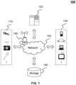
- FIG. 1 is a schematic diagram of an exemplary image processing system 100 according to some embodiments not forming part of the present invention.
- the image processing system 100 may include an imaging device 110, an image processing device 120, a terminal 130, a storage 140, a network 150, a base station 160, and/or any other suitable component for processing images in accordance with various embodiments of the disclosure.
- the imaging device 110 may generate an image including a specific object (e.g., a human face).
- the image may include a single frame that presents a static object, or a plurality of frames that present a moving object.
- the imaging device 110 may be any suitable device that is capable of generating an image.
- the imaging device 110 may include a camera, a sensor, an image recorder, or the like, or a combination thereof.
- the imaging device 110 may include a suitable type of camera, such as a fixed camera, a fixed dome camera, a covert camera, a Pan-Tilt-Zoom (PTZ) camera, a thermal camera, etc.
- the imaging device 110 may include a suitable type of sensor, such as an audio sensor, a light sensor, a wind speed sensor, or the like, or a combination thereof.
- the image(s) generated by the imaging device 110 may be stored in the storage 140, and/or sent to the image processing device 120, or the terminal 130 via the network 150.
- the image processing device 120 may process an image generated by the imaging device 110 or retrieved from another component in the image processing system 100 (e.g., the storage 140, the terminal 130). The image processing device 120 may evaluate the quality of the image and/or correct the image. For example, the image processing device 120 may correct an image if the image is designated as unqualified. In some embodiments, the image processing device 120 may be integrated with the imaging device 110 to form an integrated component of the imaging processing system 100.
- the image processing device 120 may also generate a control signal based on, for example, a feature of an object, an image of an object, a video of an object, or the like, or a combination.
- the control signal may be used to control the imaging device 110.
- the image processing device 120 may generate a control signal to control the imaging device 110 (e.g., a camera) to track an object and obtain an image of the object.
- the image processing device 120 may be any suitable device that is capable of evaluating the quality of the image and correcting the image.
- the image processing device 120 may include a high-performance computer specialized in data processing, a personal computer, a portable device, a server, a microprocessor, an integrated chip, a digital signal processor (DSP), a tablet computer, a personal digital assistant (PDA), or the like, or a combination thereof.
- the image processing device 120 may be implemented on an image processing device 200 shown in FIG. 2 .
- the terminal 130 may be connected to or communicate with the image processing device 120.
- the terminal 130 may allow one or more operators to control the production and/or display of the data (e.g., the image captured by the imaging device 110) on a display.
- the terminal 130 may include an input device, an output device, a control panel, a display (not shown in FIG. 1 ), or the like, or a combination thereof.
- An input device may be a keyboard, a touch screen, a mouse, a remote controller, a wearable device, or the like, or a combination thereof.
- the input device may include alphanumeric and other keys that may be inputted via a keyboard, a touch screen (e.g., with haptics or tactile feedback), a speech input, an eye tracking input, a brain monitoring system, or any other comparable input mechanism.
- the input information received through the input device may be communicated to the image processing device 120 via the network 150 for further processing.
- Another type of the input device may include a cursor control device, such as a mouse, a trackball, or cursor direction keys to communicate direction information and command selections to, for example, the image processing device 120 and to control cursor movement on display or another display device.
- a display may be configured to display the data received (e.g., the image captured by the imaging device 110).
- the data may include data before and/or after data processing, a request for input or parameter relating to video acquisition and/or processing, or the like, or a combination thereof.
- the display may include a liquid crystal display (LCD), a light emitting diode (LED)-based display, a flat panel display or curved screen (or television), a cathode ray tube (CRT), or the like, or a combination thereof.
- LCD liquid crystal display
- LED light emitting diode
- CRT cathode ray tube
- the network 150 may facilitate communications between various components of the image processing system 100.
- the network 150 may be a single network, or a combination of various networks.
- the network 150 may be a wired network or a wireless network.
- the wired network may include using a Local Area Network (LAN), a Wide Area Network (WAN), a ZigBee, or the like, or a combination thereof.
- the wireless network may be a Bluetooth, a Near Field Communication (NFC), a wireless local area network (WLAN), Wi-Fi, a Wireless Wide Area Network (WWAN), or the like, or a combination thereof.
- the network 150 may also include various network access points, e.g., wired or wireless access points such as the base stations 160 or Internet exchange points through which a data source may connect to the network 150 to transmit data via the network 150.
- the storage 140 may store data, image related information or parameters.
- the data may include an image (e.g., an image obtained by the imaging device 110), an audio signal, a video signal and/or communication data.
- the image related information may include a feature (e.g., pixel value) related to the object (e.g., face) in the image, frequency domain information of the image. More details regarding the image related information may be found in, for example, FIGs. 8-14 and the descriptions thereof.
- the image related parameter may include an intrinsic parameter (e.g., a focal length, a lens distortion parameter), and/or an extrinsic parameter (e.g., the pose of a camera, a position parameter of the camera) of the imaging device 110 (e.g., camera) that generates the image.
- the image related parameter may include one or more parameters used to determine the quality of the image, e.g., as described in FIG. 10 .
- the image related parameter may include a coefficient of one or more pixel matrixes for correcting the image, e.g., as described in FIG. 14 .
- the descriptions above of the image processing system 100 is provided for the purposes of illustration, and not intended to limit the scope of the present disclosure.
- various variations and modifications may be conducted under the guidance of the present disclosure.
- those variations and modifications do not depart the scope of the present disclosure.
- part or all of the image data generated by the imaging device 110 may be processed by the terminal 130.
- the imaging device 110, the image processing device 120 may be implemented in one single device configured to perform the functions of the imaging device 110 and the image processing device 120 described in this disclosure.
- the terminal 130, and the storage 140 may be combined with the image processing device 120 as a single device. Similar modifications should fall within the scope of the present disclosure.
- FIG. 2 is a schematic diagram illustrating exemplary hardware and software components of an image processing device 200 on which the imaging device 110, the image processing device 120, and/or the terminal 130 may be implemented according to some embodiments of the present disclosure.
- the image processing device 120 may be implemented on the image processing device 200 and configured to perform functions of the image processing device 120 disclosed in this disclosure.
- the image processing device 200 may be a special-purpose computer, both of which may be used to implement a data transmission system for the present disclosure.
- the image processing device 200 may be used to implement any part of the data transmission as described herein.
- the image processing device 120 may be implemented on the image processing device 200, via its hardware, software program, firmware, or a combination thereof.
- only one such computer is shown, for convenience, the computer functions relating to the image processing as described herein may be implemented in a distributed fashion on a number of similar platforms, to distribute the processing load.
- the image processing device 200 may include COM ports 250 connected to and from a network connected thereto to facilitate data communications.
- the image processing device 200 may also include a central processing unit (CPU) 220, in the form of one or more processors, for executing program instructions.
- the exemplary computer platform may include an internal communication bus 210, a program storage and data storage of different forms, such as, a disk 270, and a read only memory (ROM) 230, or a random access memory (RAM) 240, for various data files to be processed and/or transmitted by the computer.
- the exemplary computer platform may also include program instructions stored in the ROM 230, RAM 240, and/or any other type of non-transitory storage medium to be executed by the CPU 220.
- the methods and/or processes of the present disclosure may be implemented as the program instructions.
- the image processing device 200 also includes an I/O component 260, supporting input/output between the computer and other components therein.
- the image processing device 200 may also receive programming and data via network communications.
- the image processing device 200 in the present disclosure may also include multiple CPUs and/or processors, thus operations and/or method steps that are performed by one CPU and/or processor as described in the present disclosure may also be jointly or separately performed by the multiple CPUs and/or processors.
- the CPU and/or processor of the image processing device 200 executes both step A and step B
- step A and step B may also be performed by two different CPUs and/or processors jointly or separately in the image processing device 200 (e.g., the first processor executes step A and the second processor executes step B, or the first and second processors jointly execute steps A and B).
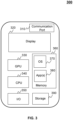
- FIG. 3 is a schematic diagram illustrating exemplary hardware and/or software components of an exemplary device 300 on which the terminal 130 may be implemented according to some embodiments of the present disclosure.
- the device 300 may be a mobile device or may be a device fixed in certain position.
- the device 300 may include a communication platform 310, a display 320, a graphic processing unit (GPU) 330, a central processing unit (CPU) 340, an I/O 350, a memory 360, and a storage 390.
- any other suitable component including but not limited to a system bus or a controller (not shown), may also be included in the device 300.
- a mobile operating system 370 e.g., iOS TM , Android TM , Windows Phone TM
- the applications 380 may include a browser or any other suitable mobile apps for receiving and rendering information relating to transmitting data in a video signal or other information from, for example, the image processing device 120.
- User interactions with the information stream may be achieved via the I/O 350 and provided to the image processing device 120 and/or other components of the image processing system 100 via the network 150.
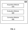
- FIG. 4 is a block diagram illustrating an exemplary image processing device 120 according to some embodiments of the present disclosure.
- the image processing device 120 may include an acquisition module 410, an evaluation module 420, and a correction module 430.
- the acquisition module 410 may obtain an image including a face.
- the image may be a two-dimensional (2D) image or a three-dimensional (3D) image.
- the evaluation module 420 may evaluate the quality of an image acquired by the acquisition module 410. In some embodiments, the evaluation module 420 may determine whether the image is qualified according to a confidence value of the object (e.g., a face) in the image. The confidence value may indicate the credibility of the object in an image when the evaluation module 420 evaluates the image. The confidence value may be in associated with a condition of the object, e.g., whether the object is occluded. Alternatively or additionally, the evaluation module 420 may determine whether the image is qualified according to a feature of the object (e.g., a face) in the image. Exemplary feature of the object may include the posture of the object, the definition of the object, or the like, or a combination thereof.
- the definition of the object may indicate the level of clarity of the object in the image.
- a larger definition of the object may correspond to a higher level of clarity of the object.
- the posture of the object may represent the position of the object or a rotational angle of the object with respect to a specific direction.
- the correction module 430 may correct an image (e.g., a 2D image, a 3D image). In some embodiments, the correction module 430 may correct an image including an object (e.g., a face) to change one or more features (e.g., the posture, the definition) of the object. For example, the correction module 430 may adjust the posture of the object presented in the image.
- an image e.g., a 2D image, a 3D image.
- the correction module 430 may correct an image including an object (e.g., a face) to change one or more features (e.g., the posture, the definition) of the object. For example, the correction module 430 may adjust the posture of the object presented in the image.
- the modules in the image processing device 120 may be connected to or communicate with each other via a wired connection or a wireless connection.
- the wired connection may include a metal cable, an optical cable, a hybrid cable, or the like, or any combination thereof.
- the wireless connection may include a Local Area Network (LAN), a Wide Area Network (WAN), a Bluetooth, a ZigBee, a Near Field Communication (NFC), or the like, or any combination thereof.
- LAN Local Area Network
- WAN Wide Area Network
- NFC Near Field Communication
- Two or more of the modules may be combined into a single module, and any one of the modules may be divided into two or more units.
- the image processing device 120 may include a storage module used to store information and/or data associated with the image to be processed.
- FIG. 5 is a block diagram illustrating an exemplary evaluation module 420 according to some embodiments of the present disclosure.
- the evaluation module 420 may include an image acquisition unit 510, a feature determination unit 520, a feature evaluation unit 530, and a quality evaluation unit 540.
- the image acquisition unit 510 may obtain an image.
- the image may include a 2D image and/or a 3D image.
- the feature determination unit 520 may determine one or more features related to an object in an image acquired from, for example, the image acquisition unit 510.
- the image may include a human face, an animal face, and/or any other objects that is suitable for image recognition.
- the present disclosure takes a human face as an example to illustrate the systems and methods thereof.
- the one or more features related to the face may include at least one of the posture of the face, the definition of the face, and/or a confidence value of the face indicating whether the face is occluded.
- the feature evaluation unit 530 may evaluate a feature related to an object (e.g., a face) in an image. In some embodiments, the feature evaluation unit 530 may evaluate whether a feature related to the object in the image satisfies a condition. For example, the feature evaluation unit 530 may determine whether the posture of the object in the image satisfies a first condition. As another example, the feature evaluation unit 530 may determine whether the definition of the object in the image satisfies a second condition. As still another example, the feature evaluation unit 530 may determine whether a confidence value of the object satisfies a third condition. The first condition, the second condition and the third condition may be described elsewhere (e.g., the process 900 in FIG. 9 and the description thereof) in the present disclosure.
- the quality evaluation unit 540 may determine whether the quality of an image is qualified. In some embodiments, the quality evaluation unit 540 may perform the determination according to one or more features determined by the feature determination unit 520 or evaluated by the feature evaluation unit 530. In some embodiments, the quality evaluation unit 540 may perform the determination associated with the image according to the frequency domain information of the image. More descriptions for determining the quality of the image may be described elsewhere (e.g., the process 1000 in FIG. 10 and the description thereof) in the present disclosure.
- the units in the evaluation module 420 may be connected to or communicated with each other via a wired connection or a wireless connection.
- the wired connection may include a metal cable, an optical cable, a hybrid cable, or the like, or any combination thereof.
- the wireless connection may include a Local Area Network (LAN), a Wide Area Network (WAN), a Bluetooth, a ZigBee, a Near Field Communication (NFC), or the like, or any combination thereof.
- LAN Local Area Network
- WAN Wide Area Network
- NFC Near Field Communication
- Two or more of the modules may be combined into a single module, and any one of the modules may be divided into two or more units.
- the evaluation module 420 may include a storage unit (not shown) used to store information and/or data associated with the image to be evaluated.
- FIG. 6 is a block diagram illustrating an exemplary correction module 430 according to some embodiments of the present disclosure.
- the correction module 430 may include a data acquisition unit 610, a point determination unit 620, a mask image determination unit 630, a symmetry determination unit 640, and a correction unit 650.
- the data acquisition unit 610 may obtain a 2D image and 3D data corresponding to the 2D image.
- the 2D image and the 3D data may include a same object (e.g., a face).
- the 3D data may be presented in the form of a 3D image, a 3D model, or the like, or a combination thereof.
- the point determination unit 620 may determine the relationship between a point (e.g., a pixel) in a 2D image and a spatial point in 3D data corresponding to the 2D image. More descriptions for determining a spatial point in the 3D data corresponding to a pixel in the 2D image may be found elsewhere (e.g., the process 1000 in FIG. 10 and the description thereof) of the present disclosure.
- the mask image determination unit 630 may determine a mask image based on a 2D image and 3D data corresponding to the 2D image.
- the symmetry determination unit 640 may determine the symmetry of an object (e.g., a face) in an image.
- the symmetry determination unit 640 may determine the symmetry of the object based on the difference between a half portion of the image and the other half portion of the image. More descriptions for determining the symmetry of a face in an image may be found elsewhere (e.g., the process 1300 in FIG. 13 and the description thereof) in the present disclosure.
- the correction unit 650 may correct an image.
- the correction unit 650 may correct the image based on the symmetry of an object in the image determined by, for example, the symmetry determination unit 640. More descriptions for correcting a 2D image may be found elsewhere (e.g., the process 1400 in FIG. 14 and the description thereof) in the present disclosure.
- the units in the correction module 430 may be connected to or communicated with each other via a wired connection or a wireless connection.
- the wired connection may include a metal cable, an optical cable, a hybrid cable, or the like, or any combination thereof.
- the wireless connection may include a Local Area Network (LAN), a Wide Area Network (WAN), a Bluetooth, a ZigBee, a Near Field Communication (NFC), or the like, or any combination thereof.
- LAN Local Area Network
- WAN Wide Area Network
- NFC Near Field Communication
- Two or more of the modules may be combined into a single module, and any one of the modules may be divided into two or more units.
- the correction module 430 may include a storage unit (not shown) used to store an image to be corrected.
- FIG. 7 is a flowchart illustrating an exemplary process 700 for correcting an image including a face according some embodiments of the present disclosure.
- the process 700 may be implemented as a set of instructions (e.g., an application) stored in the storage ROM 230, RAM 240 or hardware and/or software components of the device 300.
- the processor 220 and/or the device 300 may execute the set of instructions, and when executing the instructions, it may be configured to perform the process 700.
- the operations of the illustrated process presented below are intended to be illustrative. In some embodiments, the process 700 may be accomplished with one or more additional operations not described and/or without one or more of the operations discussed. Additionally, the order in which the operations of the process as illustrated in FIG. 7 and described below is not intended to be limiting.
- the image processing device 120 may obtain an image including a face.
- the image including a face may include a 2D image and/or a 3D image.
- the image processing device 120 may evaluate the image.
- the evaluation module 420 may evaluate the image based on at least one feature related to the face in the image such as to generate a result indicating the quality of the image (e.g., indicating whether the image is qualified).
- the image may be regarded as qualified if the at least one feature related to the face in the image satisfies a certain condition.
- the at least one feature related to the face in the image may include at least one of the posture of the face, the definition of the face, and/or a confidence value of the face indicating whether the face is occluded, or the like, or any combination thereof. More descriptions regarding the feature(s) related to the face may be found elsewhere (e.g., in FIG. 8 and the description thereof) in the disclosure.
- the operation 704 may include different stages of evaluation.
- the first stage may include evaluating the image based on at least one time domain feature related to the face.
- the second stage may include evaluating the image based on the frequency domain information related to the face.
- the different stages of evaluation may be performed sequentially or concurrently. In a sequential order of performing the stages of evaluation, the sequence of different stages of evaluation may be altered.
- the evaluation of the image based on at least one time domain feature related to the face may be performed prior to or after the evaluation of the image based on frequency domain information related to the face.
- the time domain feature related to the face may indicate the feature of the face presented in the image at a time spot or during a time interval.
- the image processing device 120 may correct the image based on the quality of the image.
- the correction module 430 may correct the image by correcting one or more features of the face. For example, the correction module 430 may adjust the posture of the face presented in the image. More descriptions of image correction may be found elsewhere (e.g., in FIGs. 11-14 and the descriptions thereof) in the present disclosure.
- FIG. 8 is a flowchart illustrating an exemplary process 800 for evaluating quality of an image including a face according to some embodiments of the present disclosure.
- the process 800 may be implemented as a set of instructions (e.g., an application) stored in the storage ROM 230, RAM 240 or hardware and/or software components of a device 300.
- the processor 220 and/or the device 300 may execute the set of instructions, and when executing the instructions, it may be configured to perform the process 800.
- the operations of the illustrated process presented below are intended to be illustrative. In some embodiments, the process 800 may be accomplished with one or more additional operations not described and/or without one or more of the operations discussed. Additionally, the order in which the operations of the process as illustrated in FIG. 8 and described below is not intended to be limiting. In some embodiments, the process 800 may be performed in connection with the operation 704.
- the evaluation module 420 may acquire an image including a face.
- the evaluation module 420 may determine at least one time domain feature related to the face in the image.
- exemplary time domain features related to the face may include the posture of the face, the definition of the face, and/or a confidence value of the face indicating whether the face is occluded, or the like, or a combination thereof.
- the posture of the face may represent the position of the face or a rotational angle of the face with respect to a specific axis.
- the rotational angle of the face may include a deflection angle of the face with respect to axis YAW (also referred to as Sa_yaw) as illustrated in FIG. 15 , a pitch angle of the face with respect to axis PITCH (also referred to as Sa_pitch) as illustrated in FIG. 15 , or a tilt angle of the face with respect to an axis ROLL (also referred to as Sa_roll) as illustrated in FIG. 15 .
- the rotational angle of the face may refer to the angle with respect to a reference position of the face, e.g., the front-view face.
- the definition of the face may represent the level of clarity of the face in the image.
- the evaluation module 420 e.g., the feature determination unit 520
- a landmark point may be a characteristic point that belongs to or represents a specific region of the face in the image.
- Exemplary landmark points of the face may include an edge point of a facial feature (e.g., a mouth corner point, an eye corner point) of the face.
- the landmark point(s) of the face may be extracted from the image based on a face landmark point localization algorithm.
- the evaluation module 420 e.g., the feature determination unit 520
- the 14 landmark points may include points at the upper edge of the eyebrow center (e.g., the landmark points 0 and 5), boundary points of the right eye (e.g., the landmark points 1 and 3), an upper edge point of the right eye (e.g., the landmark point 2), a lower edge points of the right eye (e.g., the landmark point 4)), boundary points of the left eye (e.g., the landmark points 6 and 8), an upper edge points of the left eye (e.g., the landmark point 7), an lower edge points of the left eye (e.g., the landmark point 9)), boundary points of the mouth (e.g., the landmark points 10 and 12), and upper/lower edge point of the mouth (e.g., the landmark points 11/13)).
- the size of the image may be adjusted to a uniform size (e.g., 120 pixel *120 pixel), and thus, corresponding positions of the landmark point may be determined in the adjusted image.
- the evaluation module 420 may determine at least one neighboring point around a landmark point. Then, based on the landmark points and the at least one neighboring point around each landmark point, the evaluation module 420 (e.g., the feature determination unit 520) may determine a parameter related to the definition of the face in the image, e.g., the local variance related to the landmark points, an average gradient related to the landmark points, and/or an edge width related to the landmark points.
- a parameter related to the definition of the face in the image e.g., the local variance related to the landmark points, an average gradient related to the landmark points, and/or an edge width related to the landmark points.
- the local variance may be a statistical variance of the pixel values of pixel points in a neighboring region around the landmark point.
- the neighboring region may have the shape of a triangle, a circle, or a quadrilateral, or the like.
- the neighboring region may be a 5 pixel * 5 pixel region as shown in FIG. 17 .
- the circle " ⁇ " represents the landmark point (e.g., one of the 14 landmark points shown in FIG. 16 ).
- Each grid around the landmark point represents a pixel in the neighboring region of the landmark point.
- the evaluation module 420 e.g., the feature determination unit 520
- the average gradient may be a gradient statistics of the pixel values of pixel points in a characteristic region.
- the characteristic region may be a specific region including at least one region of interest (ROI) on the face.
- ROI region of interest
- the characteristic region may be a region enclosing all or a portion of the 14 landmark points illustrated in FIG. 16 .
- the characteristic region may include a right eye region, a left eye region, and a mouth region as shown in FIG. 18 .
- the right eye region may be represented by a first circumscribed rectangle enclosing the landmark points 0 to 4.
- the left eye region may be represented by a second circumscribed rectangle enclosing the landmark points 5 to 9.
- the mouth region may be represented by a third circumscribed rectangle enclosing the landmark points 10 to 13.
- the evaluation module 420 e.g., the feature determination unit 520
- the evaluation module 420 may identify all pixel points in the characteristic region. For each of the pixel points in the characteristic region, the evaluation module 420 may determine a weighted gradient matrix.
- the evaluation module 420 may determine a local region for each of the pixel points in the characteristic region. Taking a pixel point " ⁇ " shown in FIG. 19 as an example, the evaluation module 420 may determine a 3 pixel * 3 pixel window as the local region of the pixel point " ⁇ ". The 3 pixel * 3 pixel window covers eight neighboring pixel points around the pixel point " ⁇ ". In the local region, the distance from each corner pixel point (e.g., represented by " ”) to the pixel point " ⁇ " is 2 , and the distance from each adjacent pixel point (e.g., represented by "+”) to the pixel point " ⁇ " is 1.
- the evaluation module 420 may determine a local gradient matrix by subtracting the pixel value of the pixel point " ⁇ " by the pixel value of each other pixel point in the local region. Further, the evaluation module 420 (e.g., the feature determination unit 520) may determine the weighted gradient matrix of a pixel point by weighting the local gradient matrix by the weighting matrix, e.g., by multiplying the value in the local gradient matrix with a corresponding value in the weighting matrix.
- the values in the weighted gradient matrix may be referred to as gradient values.
- the evaluation module 420 e.g., the feature determination unit 520
- the evaluation module 420 may identify the gradient values which are greater than a specific threshold (e.g., 2) as target gradient values.
- a specific threshold e.g. 2
- the number of the target values may be expressed as N
- the sum of all target values may be expressed as S.
- the evaluation module 420 e.g., the feature determination unit 520
- the edge width related to a landmark point may be represented by the number of translation pixel points associated with the landmark point.
- the evaluation module 420 e.g., the feature determination unit 520
- the certain direction may be along a normal line of a curve at the landmark point.
- the evaluation module 420 e.g., the feature determination unit 520
- the evaluation module 420 may determine the normal lines (e.g., the direction represented by arrows in FIG. 20 ) at the landmark point P and M, respectively. Then, the evaluation module 420 (e.g., the feature determination unit 520) may move the landmark point along opposite directions (e.g., the direction represented by arrows in FIG. 20 ) of the normal line by one pixel point at a time until a stopping condition is satisfied.
- the gray difference threshold may be determined according to a contrast ratio of the characteristic region (e.g., the right eye region, the left eye region, and/or the mouth region as illustrated in FIG. 18 ) where the landmark point is located.
- the evaluation module 420 e.g., the feature determination unit 520
- FC refers to the contrast ratio of the characteristic region
- avg refers to the average gray value of the characteristic region
- h ( i ) refers to the number of pixel points of which the gray value is i in the characteristic region.
- the evaluation module 420 may determine whether the at least one time domain feature related to the face satisfies a condition. In some embodiments, the evaluation module 420 (e.g., the feature evaluation unit 530) may determine whether the posture of the face in the image satisfies a first condition. In some embodiments, the evaluation module 420 (e.g., the feature evaluation unit 530) may determine whether the definition of the face in the image satisfies a second condition. In some embodiments, the evaluation module 420 (e.g., the feature evaluation unit 530) may determine whether the confidence value of the face satisfies a third condition. More descriptions of different conditions with respect to different time domain features may be found elsewhere (e.g., the process 900 in FIG. 9 and the description thereof) in the present disclosure.
- the evaluation module 420 may determine frequency domain information of the image.
- the frequency domain information of the image may also relate to the definition of the face in the image.
- the evaluation module 420 may perform a time-to-frequency domain transformation on one or more pixel values of the image. For example, the evaluation module 420 (e.g., the quality evaluation unit 540) may adjust the size of the image to a certain size (e.g., 64 pixel * 64 pixel), and perform the Fourier transformation on the one or more pixel values of the adjusted image. Additionally, the evaluation module 420 (e.g., the quality evaluation unit 540) may perform a weighted operation on the Fourier transformed image based on a weighting matrix.
- a certain size e.g., 64 pixel * 64 pixel
- the evaluation module 420 may determine the frequency domain information of the image by, e.g., adding up all weighted pixel values of the Fourier transformed image.
- the weighting matrix may be a matrix.
- the gray picture represents a weighting matrix.
- Each pixel in the gray picture may represent a matrix element.
- the matrix elements of the weighting matrix which are represented by the gray values of the corresponding pixels, may increase from the center to peripheries, but with pixel values at the edge set to 0.
- the specific values of the weighting matrix may be presented in the form of numerals as shown in FIG. 23 .
- the evaluation module 420 may adjust one or more pixel values of the time domain image to obtain another time domain image such that the high-frequency component of the frequency domain information may be concentrated in the central region.
- the evaluation module 420 may determine a quality evaluation value of the image.
- the evaluation module 420 e.g., the quality evaluation unit 540
- the quality evaluation value may be used in a subsequent operation on the image, e.g., operation 706 as illustrated in FIG. 7 . More descriptions of determining the quality evaluation value of the image may be found elsewhere (e.g., the process 1000 in FIG. 10 and the description thereof) in the present disclosure.
- FIG. 9 is a flowchart illustrating an exemplary process 900 for determining whether the quality of an image including a face is qualified according to some embodiments of the present disclosure.
- the process 900 may be implemented as a set of instructions (e.g., an application) stored in the storage ROM 230, RAM 240 or hardware and/or software components of a device 300.
- the processor 220 and/or the device 300 may execute the set of instructions, and when executing the instructions, it may be configured to perform the process 900.
- the operations of the illustrated process presented below are intended to be illustrative. In some embodiments, the process 900 may be accomplished with one or more additional operations not described and/or without one or more of the operations discussed. Additionally, the order in which the operations of the process as illustrated in FIG. 9 and described below is not intended to be limiting.
- the evaluation module 420 may evaluate the posture of a face in an image.
- the posture of the face in the image may be represented by a rotational angle of the face with respect to an axis.
- the posture of the face may be represented by three rotational angles, i.e., the deflection angle Sa_yaw with respect to the YAW axis, the pitch angle Sa_pitch with respect to the PITCH axis, and the tilt angle Sa_roll with respect to the ROLL axis.
- the YAW axis points from bottom to top
- the PITCH axis points from left to right
- the ROLL axil points from back to front of the image plane.
- the evaluation module 420 may determine whether the rotational angle with respect to a specific axis is greater than an angle threshold associated with the specific axis (e.g., the YAW angle threshold associated with the YAW axis, the PITCH angle threshold associated with the PITCH axis, and/or the ROLL angle threshold associated with the ROLL axis).
- the angle threshold may be a default value stored in a storage device (e.g., the storage device 140) or a value set by a user of the image processing device 120.
- the evaluation module 420 may determine whether the posture of the face satisfies a first condition.
- the first condition may depend on the rotational angle with respect to a specific axis.
- the first condition may include that the deflection angle Sa_yaw with respect to the YAW axis is less than the YAW angle threshold.
- the first condition may be that the deflection angle Sa_yaw is less than the YAW angle threshold and the pitch angle Sa_pitch is less than the PITCH angle threshold as well. If the posture of the face satisfies the first condition, the process 900 may proceed to 906.
- the process 900 may proceed to 916.
- the evaluation module 420 e.g., the feature evaluation unit 530
- the quality of the image is unqualified in which condition the image processing device 120 may stop processing the image.
- the evaluation module 420 may evaluate the definition of the face in the image. As described in connection with operation 804, the evaluation module 420 (e.g., the feature evaluation unit 530) may determine a parameter related to the definition of the face in the image, e.g., the local variance related to the landmark points in the image, the average gradient related to the landmark points in the image, and/or the edge width related to the landmark points in the image.
- a parameter related to the definition of the face in the image e.g., the local variance related to the landmark points in the image, the average gradient related to the landmark points in the image, and/or the edge width related to the landmark points in the image.
- the evaluation module 420 may determine whether the value of the parameter related to the definition of the face is greater than a definition threshold.
- the definition threshold may include a local variance threshold, a gradient threshold, an edge width threshold, or the like, or a combination thereof.
- the definition threshold may be a default parameter stored in a storage device (e.g., the storage device 140) or a parameter set by a user of the image processing device 120.
- the local variance threshold may be a value related to the average value of multiple local variances related to multiple landmark points (e.g., the 14 landmark points shown in FIG. 16 ).
- the gradient threshold may be a value related to the average value of multiple average gradients related to multiple characteristic regions (e.g., the three characteristic regions shown in FIG. 18 ).
- the edge width threshold may be a value related to the average value of multiple edge widths related to multiple landmark points (e.g., the 14 landmark points shown in FIG. 16 ).
- the evaluation module 420 may determine whether the definition of the face in the image satisfies a second condition.
- the second condition may depend on the relationship between the value of the parameter related to the definition of the face and the definition threshold.
- the second condition may include that each of the local variances related to the multiple landmark points (e.g., the 14 landmark points shown in FIG. 16 ) is more than the local variance threshold.
- the second condition may include that at least a portion of the local variances related to multiple landmark points (e.g., 8 landmark points of the 14 landmark points) are more than the local variance threshold.
- the second condition may include that each of the average gradients related to the characteristic regions (e.g., three characteristic regions shown in FIG. 18 ) is more than the gradient threshold.
- the second condition may include that at least a portion of the average gradients related to the multiple characteristic regions (e.g., 2 characteristic regions of the 3 characteristic regions) are more than the local variance threshold.
- the second condition may include that the average edge widths of multiple landmark points (e.g., the 14 landmark points shown in FIG. 16 or a part thereof) are more than the edge width threshold.
- the process 900 may proceed to 916. If the definition of the face satisfies the second condition, the process 900 may proceed to 910.
- the evaluation module 420 may evaluate a confidence value of the face based on the relationship between the confidence value of the face and a confidence range.
- the confidence value of the face that indicates whether the face is occluded may be determined by performing statistical analysis on a plurality of positive samples, e.g., images including occluded face and images including nonoccluded face.
- the confidence range may be a default range stored in a storage device (e.g., the storage device 140) or a parameter set by a user of the image processing device 120.
- the evaluation module 420 may determine whether the face in the image is occluded according to a third condition.
- the third condition may include that the confidence value of the face is within the confidence range. If the confidence value of the face is within the confidence range, the evaluation module 420 (e.g., the feature evaluation unit 530) may determine that the face in the image is not occluded, and direct the process 900 to 914. If the confidence value of the face is beyond the confidence range, the evaluation module 420 (e.g., the feature evaluation unit 530) may determine that face in the image is occluded, and determine the image as unqualified in 916.
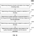
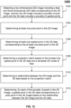
- FIG. 10 is a flowchart illustrating an exemplary process 1000 for determining a quality evaluation value of an image including a face according to some embodiments of the present disclosure.
- the process 1000 may be implemented as a set of instructions (e.g., an application) stored in the storage ROM 230, RAM 240 or hardware and/or software components of a device 300.
- the processor 220 and/or the device 300 may execute the set of instructions, and when executing the instructions, it may be configured to perform the process 1000.
- the operations of the illustrated process presented below are intended to be illustrative. In some embodiments, the process 1000 may be accomplished with one or more additional operations not described and/or without one or more of the operations discussed. Additionally, the order in which the operations of the process as illustrated in FIG. 10 and described below is not intended to be limiting.
- the evaluation module 420 may determine frequency domain information of an image including a face. More descriptions regarding the determination of frequency domain information may be found elsewhere in the disclosure, for example, the operation 808 in FIG. 8 and the description thereof.
- the evaluation module 420 may determine a first parameter related to the definition of the face.
- the first parameter may be determined according to a specific parameter associated with the definition of the face, e.g., an edge width related to one or more landmark points on the face.
- the evaluation module 420 e.g., the quality evaluation unit 540
- the evaluation module 420 e.g., the quality evaluation unit 540
- the evaluation module 420 may determine a quality evaluation component based on the frequency domain information of the face image and the first parameter. In some embodiments, the evaluation module 420 (e.g., the quality evaluation unit 540) may determine the quality evaluation component by multiplying the frequency domain information with the first parameter.
- the quality evaluation component may be determined according to formula (8) below:
- Q 1 ⁇ ⁇ ⁇ S f ⁇ ⁇ S f S f S e ⁇ ⁇ ⁇ T e S e ⁇ ⁇ ⁇ T e others
- Q 1 refers to the quality evaluation component of the image
- S f refers to the sum of all weighted pixel values of the Fourier transformed image (i.e., the frequency domain information)
- S e refers to the average edge width of multiple landmark points on the face
- T e refers to the threshold associated with the contrast ratio of the image
- ⁇ refers to the value of the first parameter (e.g., ⁇ is 1.2)
- ⁇ refers to the value of the second parameter described below (e.g., ⁇ is 0.8)
- ⁇ and ⁇ refer to coefficients related to an application scenario.
- the coefficients ⁇ or ⁇ may be changed according to different application scenarios (e.g., different requirements on the quality of the image). For example, ⁇ is set to 0.2, and ⁇ is set to 0.8.
- the threshold T e may be determined by the similar method with the determination of the gray difference threshold TH of the characteristic region, which may be found elsewhere (e.g., in formulae (4) to (7) and the descriptions thereof) in the present disclosure.
- the evaluation module 420 may determine a second parameter related to the posture of the face.
- the second parameter may be determined according to a specific parameter associated with the posture of the face, e.g., the rotational angle of the face with respect to an axis (e.g., the deflection anlge Sa_yaw, or the pitch angle Sa_pitch).
- the evaluation module 420 e.g., the quality evaluation unit 540
- the second parameter may have a larger value.
- the second parameter may have a smaller value if the rotational angle of the face with respect to an axis resides in a smaller angle range (e.g., the Sa_yaw and/or Sa_pitch is in a smaller range).
- the evaluation module 420 may determine a quality evaluation value based on the quality evaluation component and the second parameter. In some embodiments, the evaluation module 420 (e.g., the quality evaluation unit 540) may determine the quality evaluation value of the image by multiplying the quality evaluation component with the second parameter.
- Q 1 refers to the quality evaluation component of the image
- Q refers to the quality evaluation value of the image
- Sa_yaw refers to the deflection angle of the face with respect to the YAW axis
- Sa_pitch refers to the pitch angle of the face with respect to the PITCH axis.
- the quality evaluation value of the image may have a larger value if the face in the image is rotated by a small rotational angle (e.g., smaller deflection angle Sa_yaw and/or Sa_pitch).
- FIG. 11 is a flowchart illustrating an exemplary process 1100 for correcting a 2D image including a face according to some embodiments not forming part of the present invention.
- the process 1100 may be implemented as a set of instructions (e.g., an application) stored in the storage ROM 230, RAM 240 or hardware and/or software components of a device 300.
- the processor 220 and/or the device 300 may execute the set of instructions, and when executing the instructions, it may be configured to perform the process 1100.
- the operations of the illustrated process presented below are intended to be illustrative. In some embodiments, the process 1100 may be accomplished with one or more additional operations not described and/or without one or more of the operations discussed. Additionally, the order in which the operations of the process as illustrated in FIG. 11 and described below is not intended to be limiting.
- the correction module 430 may obtain a two dimensional (2D) image including a face and three dimensional (3D) data corresponding to the 2D image.
- the 2D image may include a plurality of pixels (also referred to as pixel points) and the 3D data may include a 3D image or 3D model which comprises a plurality of voxels (also referred to as spatial points).
- the plurality of pixels in the 2D image may be represented by X and Y coordinates
- the spatial points in the 3D data may be represented by X, Y, and Z coordinates.
- the correction module 430 may determine, for each of the plurality of pixels in the 2D image, a spatial point in the 3D data corresponding to the pixel in the 2D image.
- the correction module 430 e.g., the point determination unit 620
- the projection matrix may be a matrix representing the relationship between the pixels in the 2D image and the spatial points in the 3D data. More description regarding the determination of the projection matrix may be found elsewhere (e.g., FIG. 12 and the description thereof) in the present disclosure.
- the correction module 430 may determine a mask image based on the spatial points in the 3D data corresponding to the plurality of pixels in the 2D image.
- the mask image may be a 2D image which includes symmetry related information of the face in the 2D image.
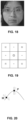
- FIG. 25 shows an exemplary mask image for the 2D image including a face as shown in FIG. 24 .
- the correction module 430 may associate the normal direction of a corresponding the spatial point in the 3D data with the value of the pixel.
- the normal lines of the spatial points in the 3D data corresponding to the part of the face may be parallel to the Z direction, or have a relatively small angle with the Z direction.
- the angle between the directions of normal line of the spatial points in the 3D data corresponding to the part may form a relatively large angle with the Z direction.
- the part of the face where the spatial point is located may be regarded as occluded or partially occluded.
- the Z direction may refer to the direction which is perpendicular to the plane of the 2D image.
- the correction module 430 may determine a symmetry related parameter of the face in the 2D image based on the mask image.
- the pixel values are associated with the normal lines of spatial points in the mask image
- different portions of the mask image may be processed according to a specific algorithm to form the symmetry related parameter of the face. More descriptions for determining the symmetry related parameter of the face in the 2D image may be found elsewhere (e.g., the process 1300 in FIG. 13 and the description thereof) in the present disclosure.
- the correction module 430 may correct the 2D image based on the symmetry related parameter of the face in the 2D image and the mask image. In some embodiments, the correction module 430 may correct the 2D image to present the front view of the face in a corrected 2D image. More description for correcting the 2D image based on the symmetry related parameter of the face in the 2D image may be found elsewhere (e.g., FIG. 14 and the description thereof) in the present disclosure.
- FIG. 12 is a flowchart illustrating an exemplary process 1200 for determining, for each of the plurality of pixels in a 2D image including a face, a spatial point in a 3D data corresponding to a pixel in the 2D image according to some embodiments not forming part of the present invention.
- the process 1200 may be implemented as a set of instructions (e.g., an application) stored in the storage ROM 230, RAM 240 or hardware and/or software components of a device 300.
- the processor 220 and/or the device 300 may execute the set of instructions, and when executing the instructions, it may be configured to perform the process 1200.
- the operations of the illustrated process presented below are intended to be illustrative. In some embodiments, the process 1200 may be accomplished with one or more additional operations not described and/or without one or more of the operations discussed. Additionally, the order in which the operations of the process as illustrated in FIG. 12 and described below is not intended to be limiting.
- the correction module 430 may obtain a 2D image including a face and 3D data corresponding to the 2D image as described in connection with operation 1102.
- the correction module 430 may determine at least one pixel point in the 2D image.
- the at least one pixel point may include a landmark point, e.g., an edge point of a facial feature (e.g., a mouth corner point, an eye corner point) of the face in the 2D image.
- the at least one pixel point in the 2D image may include landmark points as described elsewhere in the disclosure and interpolation points that are interpolated between the landmark points.
- the correction module 430 may determine at least one spatial point in the 3D data corresponding to the at least one pixel point in the 2D image.
- the correction module 430 may determine the at least one spatial point in the 3D data based on a mapping process. For example, in a mapping process, the correction module 430 may identify the X, Y coordinates of the at least one pixel point in the 2D image, and then determine the at least one spatial point in the 3D data by identifying spatial points having same X, Y coordinates with that of the at least one pixel point in the 2D image.
- the correction module 430 may determine a projection matrix based on the at least one spatial point in the 3D data and a template 3D model of face.
- the projection matrix may be a matrix representing a relationship between the spatial points in the 3D data and the pixel points in the 2D images (e.g., the rotation matrix R, the translation matrix T illustrated in formula (10)).
- the template 3D model of face may be generated based on a plurality of 2D images and corresponding 3D data. For each 2D image, multiple landmark points (e.g., the eye corner points, upper and lower edge points of the left eye and/or the right eye) may be extracted. Then, a mapping process as described elsewhere in the disclosure may be performed to map corresponding spatial points in the 3D data with the landmark points of the plurality of 2D images. For example, a plurality of left eye corner points may be identified in the 3D data. Then, an average coordinate of the left eye corner point may be determined according to the plurality of left eye corner points in the 3D data. Similarly, the average coordinate of the upper edge point of the left/right eye, or the lower edge point of the left/right eye may be determined. Thus, the template 3D model of face may be determined according to the average coordinates of various spatial points in the 3D data.
- multiple landmark points e.g., the eye corner points, upper and lower edge points of the left eye and/or the right eye
- the correction module 430 may determine a relationship between the 2D image and the 3D data based on the projection matrix.
- the relationship between the 2D image and the 3D data may be illustrated by formula (10) below:
- X 2D refers to a matrix associated with the plurality of pixel points in the 2D image
- X 3 D refers to a matrix associated with the plurality of spatial points in the 3D data
- F x , F y , C x , and C y refer to camera parameters
- R refers to a rotation matrix
- T refers to a translation matrix
- M 1 M 2 which is defined by the camera parameters
- the rotation matrix and the translation matrix refers to the projection matrix.
- the correction module 430 may determine, for each of the plurality of pixel points in the 2D image, a corresponding spatial point in the 3D data to a pixel in the 2D image based on the relationship between the 2D image and the 3D data.
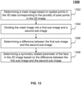
- FIG. 13 is a flowchart illustrating an exemplary process 1300 for determining a symmetry related parameter of the face in a 2D image according to some embodiments not forming part of the present invention.
- the process 1300 may be implemented as a set of instructions (e.g., an application) stored in the storage ROM 230, RAM 240 or hardware and/or software components of a device 300.
- the processor 220 and/or the device 300 may execute the set of instructions, and when executing the instructions, it may be configured to perform the process 1300.
- the operations of the illustrated process presented below are intended to be illustrative. In some embodiments, the process 1300 may be accomplished with one or more additional operations not described and/or without one or more of the operations discussed. Additionally, the order in which the operations of the process as illustrated in FIG. 13 and described below is not intended to be limiting.
- the correction module 430 may determine a mask image based on spatial points in the 3D data corresponding to the plurality of pixel points in the 2D image. In some embodiments, for each pixel in the mask image, the pixel value may be in associated with the normal line of a spatial point in the 3D data corresponding to the pixel. For illustration purpose, the correction module 430 may determine the values of the pixels in the mask image based on a binary threshold.
- the binary threshold may be a default value stored in a storage device (e.g., the storage device 140) or a value set by a user of the image processing device 120.
- the value of the pixel in the mask image may be set to 1, otherwise, the value of the pixel may be set to 0.
- the correction module 430 may divide the mask image into a first sub-image and a second sub-image.
- the correction module 430 may symmetrically divide the mask image along the vertical center line to generate a left mage (i.e., the first sub-image) and a right image (i.e., the right sub-image).
- the correction module 430 may determine a difference between the first sub-image and the second sub-image.
- the correction module 430 may determine the sum of the pixel values in the first sub-image and the sum of the pixel values in the second sub-image, respectively.
- the difference between the first sub-image and the second sub-image may be in associated with the difference between the sum of the pixel values in the first sub-image and the sum of the pixel values in the second sub-image.
- the correction module 430 may normalize the difference between the first sub-image and the second sub-image such that the normalized difference may be within a preset range.
- the correction module 430 may determine a symmetry related parameter of the face in the 2D image based on the difference between the first sub-image and the second sub-image.
- the above description for determining the symmetry related parameter of the face in a 2D image is merely provided for the purpose of illustration, and not intended to limit the scope of the present disclosure.
- multiple variations and modifications may be made under the teachings of the present disclosure.
- those variations and modifications do not depart from the scope of the present disclosure.
- the values of the first symmetry related parameter of the first sub-image and the second symmetry related parameter of the second sub-image may be set to other value, such as [0.2 2.0].
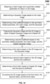
- FIG. 14 is a flowchart illustrating an exemplary process 1400 for correcting a 2D image according to some embodiments not forming part of the present invention.
- the process 1400 may be implemented as a set of instructions (e.g., an application) stored in the storage ROM 230, RAM 240 or hardware and/or software components of a device 300.
- the processor 220 and/or the device 300 may execute the set of instructions, and when executing the instructions, it may be configured to perform the process 1400.
- the operations of the illustrated process presented below are intended to be illustrative. In some embodiments, the process 1400 may be accomplished with one or more additional operations not described and/or without one or more of the operations discussed. Additionally, the order in which the operations of the process as illustrated in FIG. 14 and described below is not intended to be limiting.
- the correction module 430 may obtain a mask image and a symmetry related parameter of a face in a 2D image as described in connection with operations 1304 and 1308. In some embodiments, the correction module 430 may normalize the mask image to render the pixel values of the normalized mask image within a specific range, e.g., from 0 to 1.
- the correction module 430 may determine a Gaussian image by performing a Gaussian transformation on the mask image. In some embodiments, the correction module 430 may determine the Gaussian image by performing Gaussian kernel blurring on the mask image. Taking the Gaussian image shown in FIG. 26 as an example, the Gaussian image may be obtained by performing the one-dimensional Gaussian downward broadening process on the mask image shown in FIG. 25 .
- the correction module 430 may flip the Gaussian image and the 2D image.
- To flip an image may indicate symmetrically turning the left side of the image to the right, and turning the right side of the image to the left.
- W 0 sym 1 ⁇ W 0 org
- Wlr (2) refers to the second symmetry related parameter of the second sub-image
- W gauss ' refers to the pixel matrix of the flipped Gaussian image
- W 0 org is determined according to formula (14).
- the correction module 430 may determine a first matrix based on the 2D image and the Gaussian image.
- the correction module 430 may determine a second matrix based on the 2D image and the first coefficient.
- the correction module 430 may determine a third matrix based on the flipped 2D image and the second coefficient.
- the correction module 430 may correct the 2D image based on the first matrix, the second matrix, and the third matrix.
- the correction module 430 may determine the corrected matrix of the 2D image by adding up the first matrix, the second matrix, and the third matrix.
- computer hardware platforms may be used as the hardware platform(s) for one or more of the elements described herein.
- a computer with user interface elements may be used to implement a personal computer (PC) or any other type of work station or terminal device.
- PC personal computer
- a computer may also act as a server if appropriately programmed.
- aspects of the present disclosure may be illustrated and described herein in any of a number of patentable classes or context including any new and useful process, machine, manufacture, or composition of matter, or any new and useful improvement thereof. Accordingly, aspects of the present disclosure may be implemented entirely hardware, entirely software (including firmware, resident software, micro-code, etc.) or combining software and hardware implementation that may all generally be referred to herein as a "unit,” “module,” or “system.” Furthermore, aspects of the present disclosure may take the form of a computer program product embodied in one or more computer readable media having computer readable program code embodied thereon.
- a computer readable signal medium may include a propagated data signal with computer readable program code embodied therein, for example, in baseband or as part of a carrier wave. Such a propagated signal may take any of a variety of forms, including electro-magnetic, optical, or the like, or any suitable combination thereof.
- a computer readable signal medium may be any computer readable medium that is not a computer readable storage medium and that may communicate, propagate, or transport a program for use by or in connection with an instruction execution system, apparatus, or device.
- Program code embodied on a computer readable signal medium may be transmitted using any appropriate medium, including wireless, wireline, optical fiber cable, RF, or the like, or any suitable combination of the foregoing.
- Computer program code for carrying out operations for aspects of the present disclosure may be written in any combination of one or more programming languages, including an object-oriented programming language such as Java, Scala, Smalltalk, Eiffel, JADE, Emerald, C++, C#, VB. NET, Python or the like, conventional procedural programming languages, such as the "C" programming language, Visual Basic, Fortran 2003, Perl, COBOL 2002, PHP, ABAP, dynamic programming languages such as Python, Ruby and Groovy, or other programming languages.
- the program code may execute entirely on the user's computer, partly on the user's computer, as a stand-alone software package, partly on the user's computer and partly on a remote computer or entirely on the remote computer or server.
- the remote computer may be connected to the user's computer through any type of network, including a local area network (LAN) or a wide area network (WAN), or the connection may be made to an external computer (for example, through the Internet using an Internet Service Provider) or in a cloud computing environment or offered as a service such as a Software as a Service (SaaS).
- LAN local area network
- WAN wide area network
- SaaS Software as a Service
Landscapes
- Engineering & Computer Science (AREA)
- General Physics & Mathematics (AREA)
- Physics & Mathematics (AREA)
- Multimedia (AREA)
- Theoretical Computer Science (AREA)
- Quality & Reliability (AREA)
- Oral & Maxillofacial Surgery (AREA)
- General Health & Medical Sciences (AREA)
- Human Computer Interaction (AREA)
- Health & Medical Sciences (AREA)
- Computer Vision & Pattern Recognition (AREA)
- Image Processing (AREA)
- Image Analysis (AREA)
Claims (10)
- Système électronique de reconnaissance faciale, comprenant :une unité d'obtention d'image (410, 510) configurée pour obtenir une image incluant un visage ;une ou plusieurs unités de traitement d'image (520, 530, 540) raccordées à l'unité d'obtention d'image, dans lequel, en fonctionnement, les une ou plusieurs unités de traitement d'image :déterminent au moins une caractéristique de domaine temporel relative au visage dans l'image, la au moins une caractéristique de domaine temporel relative au visage indiquant une ou plusieurs caractéristiques du visage présenté dans l'image à un instant donné et incluant une posture du visage représentant une position du visage ou un angle de rotation du visage par rapport à un axe, une définition du visage représentant un niveau de clarté du visage dans l'image, et une valeur de confiance du visage indiquant si le visage est occulté ;déterminent des informations de domaine fréquentiel relatives au visage dans l'image, les informations de domaine fréquentiel relatives au visage étant des informations déterminées sur la base de l'image après une transformation de domaine temporel en domaine fréquentiel, dans lequel, pour déterminer les informations de domaine fréquentiel de l'image, les une ou plusieurs unités de traitement d'image :effectuent la transformation de domaine temporel en domaine fréquentiel sur des valeurs de pixel de l'image ;pondèrent les valeurs de pixel transformées du domaine temporel en domaine fréquentiel de l'image sur la base d'une matrice de pondération ; etdéterminent les informations de domaine fréquentiel de l'image sur la base des valeurs de pixel pondérées de l'image ;déterminent si la au moins une caractéristique de domaine temporel relative au visage satisfait à une condition, la condition incluant si la posture du visage satisfait à une première condition, si la définition du visage dans l'image satisfait à une deuxième condition, et si le visage dans l'image est occulté sur la base d'une troisième condition ;déterminent une valeur d'évaluation de qualité de l'image sur la base des informations de domaine fréquentiel relatives au visage dans l'image, dans lequel, pour évaluer la qualité de l'image, les une ou plusieurs unités de traitement d'image :déterminent une valeur d'un premier paramètre, le premier paramètre se rapportant à la définition du visage ;déterminent une composante d'évaluation de qualité en multipliant les informations de domaine fréquentiel de l'image par le premier paramètre ;déterminent une valeur d'un second paramètre, le second paramètre se rapportant à l'angle de rotation du visage par rapport à l'axe ; etdéterminent la valeur d'évaluation de qualité de l'image en multipliant la composante d'évaluation de qualité par la valeur du second paramètre ; etévaluent une qualité de l'image sur la base de la détermination que la au moins une caractéristique de domaine temporel relative au visage satisfait, ou non, à la condition, et de la valeur d'évaluation de qualité, dans lequel, pour évaluer la qualité de l'image, les une ou plusieurs unités de traitement d'image :à la suite d'une détermination que la au moins une caractéristique de domaine temporel ne satisfait pas à la condition, déterminent que la qualité de l'image n'est pas qualifiée, età la suite d'une détermination que la au moins une caractéristique de domaine temporel satisfait à la condition, évaluent la qualité de l'image sur la base de la valeur d'évaluation de qualité de l'image ; etcorrigent l'image sur la base de la qualité de l'image.
- Système selon la revendication 1, dans lequel, pour déterminer la définition du visage dans l'image, les une ou plusieurs unités de traitement d'image :extraient au moins un point de repère dans l'image, le au moins un point de repère étant par rapport à une région d'intérêt du visage ;déterminent au moins un point voisin du au moins un point de repère ; etdéterminent, sur la base du au moins un point de repère et du au moins un point voisin, une variance locale relative à le au moins un point de repère, à le un gradient moyen relatif à le au moins un point de repère, ou une largeur de bord relative à le au moins un point de repère dans l'image.
- Système selon la revendication 2, dans lequel, pour déterminer une valeur d'un premier paramètre, les une ou plusieurs unités de traitement d'image :
divisent différentes plages de valeurs relatives à la largeur de bord sur la base d'un seuil associé à un contraste de l'image, chacune des différentes plages de valeurs correspondant à une valeur différente du premier paramètre. - Système selon la revendication 2, dans lequel, pour déterminer une valeur d'un second paramètre, les une ou plusieurs unités de traitement d'image :
divisent différentes plages d'angles relatives à l'angle de rotation du visage par rapport à l'axe, chacune des différentes plages d'angle correspondant à une valeur différente du second paramètre. - Système selon la revendication 1, dans lequel, pour déterminer les informations de domaine fréquentiel de l'image sur la base des valeurs de pixel pondérées de l'image, les une ou plusieurs unités de traitement d'image :
additionnent les valeurs de pixel pondérées de l'image après la transformation de domaine temporel en domaine fréquentiel. - Procédé de reconnaissance faciale qui est mis en oeuvre sur au moins un dispositif électronique de reconnaissance faciale, le procédé comprenant :l'obtention d'une image incluant un visage ;la détermination d'au moins une caractéristique de domaine temporel relative au visage dans l'image, la au moins une caractéristique de domaine temporel relative au visage indiquant une ou plusieurs caractéristiques du visage présenté dans l'image à un instant donné et incluant une posture du visage représentant une position du visage ou un angle de rotation du visage par rapport à un axe, une définition du visage représentant un niveau de clarté du visage dans l'image, et une valeur de confiance du visage indiquant si le visage est occulté, la détermination d'informations de domaine fréquentiel relatives au visage dans l'image, les informations de domaine fréquentiel relatives au visage étant des informations déterminées sur la base de l'image après une transformation de domaine temporel en domaine fréquentiel ;dans lequel la détermination des informations de domaine fréquentiel de l'image inclut :la réalisation de la transformation de domaine temporel en domaine fréquentiel sur des valeurs de pixel de l'image ;la pondération des valeurs de pixel transformées du domaine temporel en domaine fréquentiel de l'image sur la base d'une matrice de pondération ; etla détermination des informations de domaine fréquentiel de l'image sur la base des valeurs de pixel pondérées de l'image ;la détermination pour savoir si la au moins une caractéristique de domaine temporel relative au visage satisfait à une condition, la condition incluant si la posture du visage satisfait à une première condition, si la définition du visage dans l'image satisfait à une deuxième condition, et si le visage dans l'image est occulté sur la base d'une troisième condition ;la détermination d'une valeur d'évaluation de qualité de l'image sur la base des informations de domaine fréquentiel relatives au visage dans l'image, dans lequel l'évaluation de la qualité de l'image inclut :la détermination d'une valeur d'un premier paramètre, le premier paramètre se rapportant à la définition du visage ;la détermination d'une composante d'évaluation de qualité en multipliant les informations de domaine fréquentiel de l'image par le premier paramètre ;la détermination d'une valeur d'un second paramètre, le second paramètre se rapportant à l'angle de rotation du visage par rapport à l'axe ; etla détermination de la valeur d'évaluation de qualité de l'image en multipliant la composante d'évaluation de qualité par la valeur du second paramètre ; etl'évaluation d'une qualité de l'image sur la base de la détermination que la au moins une caractéristique de domaine temporel relative au visage satisfait, ou non, à la condition et de la valeur d'évaluation de qualité, dans lequel l'évaluation de la qualité de l'image inclut :à la suite d'une détermination que la au moins une caractéristique de domaine temporel ne satisfait pas à la condition, la détermination que la qualité de l'image n'est pas qualifiée ; età la suite d'une détermination que la au moins une caractéristique de domaine temporel satisfait à la condition, l'évaluation de la qualité de l'image sur la base de la valeur d'évaluation de qualité de l'image ; etla correction de l'image sur la base de la qualité de l'image.
- Procédé selon la revendication 6, dans lequel la détermination de la définition du visage dans l'image inclut :l'extraction d'au moins un point de repère dans l'image, le au moins un point de repère étant par rapport à une région d'intérêt du visage ;la détermination d'au moins un point voisin du au moins un point de repère ; etla détermination, sur la base du au moins un point de repère et du au moins un point voisin, d'une variance locale relative à le au moins un point de repère, d'un gradient moyen relatif à le au moins un point de repère, ou d'une largeur de bord relative à le au moins un point de repère dans l'image.
- Procédé selon la revendication 7, dans lequel la détermination d'une valeur d'un premier paramètre inclut :
la division de différentes plages de valeurs relatives à la largeur de bord sur la base d'un seuil associé à un contraste de l'image, chacune des différentes plages de valeurs correspondant à une valeur différente du premier paramètre. - Procédé selon la revendication 7, dans lequel la détermination d'une valeur d'un second paramètre inclut :
la division de différentes plages d'angle relatives à l'angle de rotation du visage par rapport à l'axe, chacune des différentes plages d'angle correspondant à une valeur différente du second paramètre. - Procédé selon la revendication 6, dans lequel la détermination des informations de domaine fréquentiel de l'image sur la base des valeurs de pixel pondérées de l'image inclut :
l'addition des valeurs de pixel pondérées de l'image après la transformation de domaine temporel en domaine fréquentiel.
Applications Claiming Priority (3)
| Application Number | Priority Date | Filing Date | Title |
|---|---|---|---|
| CN201611237293.0A CN106803067B (zh) | 2016-12-28 | 2016-12-28 | 一种人脸图像质量评估方法及装置 |
| CN201611237296.4A CN106778660B (zh) | 2016-12-28 | 2016-12-28 | 一种人脸姿态校正方法及装置 |
| PCT/CN2017/118598 WO2018121523A1 (fr) | 2016-12-28 | 2017-12-26 | Procédés, systèmes, et supports pour l'évaluation d'images |
Publications (3)
| Publication Number | Publication Date |
|---|---|
| EP3545467A1 EP3545467A1 (fr) | 2019-10-02 |
| EP3545467A4 EP3545467A4 (fr) | 2019-12-18 |
| EP3545467B1 true EP3545467B1 (fr) | 2024-10-23 |
Family
ID=62707933
Family Applications (1)
| Application Number | Title | Priority Date | Filing Date |
|---|---|---|---|
| EP17888585.1A Active EP3545467B1 (fr) | 2016-12-28 | 2017-12-26 | Procédé et système pour l'évaluation de la qualité d'images de visage |
Country Status (3)
| Country | Link |
|---|---|
| US (2) | US11120252B2 (fr) |
| EP (1) | EP3545467B1 (fr) |
| WO (1) | WO2018121523A1 (fr) |
Families Citing this family (9)
| Publication number | Priority date | Publication date | Assignee | Title |
|---|---|---|---|---|
| EP3545467B1 (fr) | 2016-12-28 | 2024-10-23 | Zhejiang Dahua Technology Co., Ltd. | Procédé et système pour l'évaluation de la qualité d'images de visage |
| KR102748556B1 (ko) | 2020-04-16 | 2025-01-02 | 삼성전자주식회사 | 라이브니스 검사 방법 및 장치 |
| CN113040755B (zh) * | 2020-10-28 | 2022-01-04 | 北京新赛点体育投资股份有限公司 | 应用网络监控的状态调整平台及方法 |
| EP4113464A1 (fr) * | 2021-06-30 | 2023-01-04 | Tobii AB | Système de suivi des yeux |
| US20230274377A1 (en) * | 2021-12-13 | 2023-08-31 | Extramarks Education India Pvt Ltd. | An end-to-end proctoring system and method for conducting a secure online examination |
| CN114445386B (zh) * | 2022-01-29 | 2023-02-24 | 泗阳三江橡塑有限公司 | 一种基于人工智能的pvc管件质量检测评估方法及系统 |
| CN115756177B (zh) * | 2023-01-10 | 2023-05-12 | 深圳市心流科技有限公司 | 用户评价方法、装置、设备及存储介质 |
| WO2024192727A1 (fr) * | 2023-03-22 | 2024-09-26 | 中国科学院深圳先进技术研究院 | Procédé d'évaluation quantitative de qualité d'image ultrasonore |
| CN120612279A (zh) * | 2025-04-18 | 2025-09-09 | 煤炭科学研究总院有限公司 | 视频流的质量检测方法、装置、电子设备和存储介质 |
Citations (1)
| Publication number | Priority date | Publication date | Assignee | Title |
|---|---|---|---|---|
| US20190318154A1 (en) * | 2016-12-28 | 2019-10-17 | Zhejiang Dahua Technology Co., Ltd. | Methods, systems, and media for evaluating images |
Family Cites Families (22)
| Publication number | Priority date | Publication date | Assignee | Title |
|---|---|---|---|---|
| US7512286B2 (en) * | 2003-10-27 | 2009-03-31 | Hewlett-Packard Development Company, L.P. | Assessing image quality |
| KR100559471B1 (ko) * | 2003-12-17 | 2006-03-10 | 한국전자통신연구원 | 대칭축을 이용한 얼굴 검출 시스템 및 방법 |
| CN101567044B (zh) * | 2009-05-22 | 2012-08-22 | 北京大学 | 一种人脸图像质量检测方法 |
| KR101184097B1 (ko) * | 2009-12-07 | 2012-09-18 | 삼성전자주식회사 | 얼굴 정면포즈 판단 방법 |
| CN101794389B (zh) | 2009-12-30 | 2012-06-13 | 中国科学院计算技术研究所 | 一种人脸图像光照预处理方法 |
| JP5973773B2 (ja) | 2012-04-26 | 2016-08-23 | 株式会社トプコン | 回転角検出装置 |
| CN102799877A (zh) | 2012-09-11 | 2012-11-28 | 上海中原电子技术工程有限公司 | 人脸图像筛选方法及系统 |
| CN103605965A (zh) | 2013-11-25 | 2014-02-26 | 苏州大学 | 一种多姿态人脸识别方法和装置 |
| US9727776B2 (en) * | 2014-05-27 | 2017-08-08 | Microsoft Technology Licensing, Llc | Object orientation estimation |
| US9235775B2 (en) * | 2014-06-08 | 2016-01-12 | Uber Technologies, Inc. | Entrance detection from street-level imagery |
| CN104408399A (zh) | 2014-10-28 | 2015-03-11 | 小米科技有限责任公司 | 人脸图像处理方法及装置 |
| CN105825163A (zh) * | 2015-01-09 | 2016-08-03 | 杭州海康威视数字技术股份有限公司 | 一种人脸图像的检索系统及方法 |
| US10134177B2 (en) | 2015-01-15 | 2018-11-20 | Samsung Electronics Co., Ltd. | Method and apparatus for adjusting face pose |
| CN105844276A (zh) | 2015-01-15 | 2016-08-10 | 北京三星通信技术研究有限公司 | 人脸姿态校正方法和装置 |
| KR20160119932A (ko) * | 2015-04-06 | 2016-10-17 | 한국과학기술원 | 품질 측정 기반의 얼굴 인식 방법 및 장치 |
| CN106202089B (zh) | 2015-05-04 | 2020-03-27 | 阿里巴巴集团控股有限公司 | 一种确定图片质量和网页展示的方法及设备 |
| CN104834919B (zh) | 2015-05-20 | 2018-05-15 | 东南大学 | 一种基于轮廓线的三维人脸迭代预处理和特征点提取方法 |
| US9329762B1 (en) | 2015-06-02 | 2016-05-03 | Interactive Memories, Inc. | Methods and systems for reversing editing operations in media-rich projects |
| CN106056562B (zh) | 2016-05-19 | 2019-05-28 | 京东方科技集团股份有限公司 | 一种人脸图像处理方法、装置及电子设备 |
| CN106778660B (zh) * | 2016-12-28 | 2019-11-15 | 浙江大华技术股份有限公司 | 一种人脸姿态校正方法及装置 |
| CN106803067B (zh) * | 2016-12-28 | 2020-12-08 | 浙江大华技术股份有限公司 | 一种人脸图像质量评估方法及装置 |
| US10474880B2 (en) * | 2017-03-15 | 2019-11-12 | Nec Corporation | Face recognition using larger pose face frontalization |
-
2017
- 2017-12-26 EP EP17888585.1A patent/EP3545467B1/fr active Active
- 2017-12-26 WO PCT/CN2017/118598 patent/WO2018121523A1/fr not_active Ceased
-
2019
- 2019-06-28 US US16/455,824 patent/US11120252B2/en active Active
-
2021
- 2021-09-08 US US17/447,067 patent/US11615643B2/en active Active
Patent Citations (1)
| Publication number | Priority date | Publication date | Assignee | Title |
|---|---|---|---|---|
| US20190318154A1 (en) * | 2016-12-28 | 2019-10-17 | Zhejiang Dahua Technology Co., Ltd. | Methods, systems, and media for evaluating images |
Also Published As
| Publication number | Publication date |
|---|---|
| EP3545467A1 (fr) | 2019-10-02 |
| US11615643B2 (en) | 2023-03-28 |
| US20210406521A1 (en) | 2021-12-30 |
| EP3545467A4 (fr) | 2019-12-18 |
| WO2018121523A1 (fr) | 2018-07-05 |
| US20190318154A1 (en) | 2019-10-17 |
| US11120252B2 (en) | 2021-09-14 |
Similar Documents
| Publication | Publication Date | Title |
|---|---|---|
| US11615643B2 (en) | Methods, systems, and media for evaluating images | |
| US10861177B2 (en) | Methods and systems for binocular stereo vision | |
| EP3576017B1 (fr) | Procédé et système de détermination de pose d'objet dans une image, et support d'informations | |
| US11436702B2 (en) | Systems and methods for super-resolusion image reconstruction | |
| KR102299847B1 (ko) | 얼굴 인증 방법 및 장치 | |
| JP6629513B2 (ja) | ライブネス検査方法と装置、及び映像処理方法と装置 | |
| US11647176B2 (en) | Methods and systems for camera calibration | |
| WO2018121013A1 (fr) | Systèmes et procédés de détection d'objets dans des images | |
| US11361587B2 (en) | Age recognition method, storage medium and electronic device | |
| US11842535B2 (en) | Systems and methods for license plate recognition | |
| EP3791356B1 (fr) | Correction de distorsions de perspective sur des visages | |
| WO2022247406A1 (fr) | Systèmes et procédés de détermination d'images de trames clés de données vidéo | |
| JP2019117577A (ja) | プログラム、学習処理方法、学習モデル、データ構造、学習装置、および物体認識装置 | |
| WO2019080702A1 (fr) | Procédé et appareil de traitement d'images | |
| US11804032B2 (en) | Method and system for face detection | |
| US12327299B2 (en) | Facial expression image processing method and apparatus, and electronic device | |
| CN109345460B (zh) | 用于矫正图像的方法和装置 | |
| US20230036366A1 (en) | Image attribute classification method, apparatus, electronic device, medium and program product | |
| CN113971671B (zh) | 实例分割方法、装置、电子设备及存储介质 | |
| CN113505672B (zh) | 虹膜采集装置、虹膜采集方法、电子设备和可读介质 | |
| WO2021078133A1 (fr) | Systèmes et procédés de traitement d'images | |
| CN109410274B (zh) | 一种高帧频条件下典型非合作目标要害点实时定位方法 | |
| US20200364861A1 (en) | Systems and methods for identifying a body motion |
Legal Events
| Date | Code | Title | Description |
|---|---|---|---|
| STAA | Information on the status of an ep patent application or granted ep patent |
Free format text: STATUS: THE INTERNATIONAL PUBLICATION HAS BEEN MADE |
|
| PUAI | Public reference made under article 153(3) epc to a published international application that has entered the european phase |
Free format text: ORIGINAL CODE: 0009012 |
|
| STAA | Information on the status of an ep patent application or granted ep patent |
Free format text: STATUS: REQUEST FOR EXAMINATION WAS MADE |
|
| 17P | Request for examination filed |
Effective date: 20190628 |
|
| AK | Designated contracting states |
Kind code of ref document: A1 Designated state(s): AL AT BE BG CH CY CZ DE DK EE ES FI FR GB GR HR HU IE IS IT LI LT LU LV MC MK MT NL NO PL PT RO RS SE SI SK SM TR |
|
| AX | Request for extension of the european patent |
Extension state: BA ME |
|
| A4 | Supplementary search report drawn up and despatched |
Effective date: 20191115 |
|
| RIC1 | Information provided on ipc code assigned before grant |
Ipc: G06K 9/00 20060101AFI20191111BHEP |
|
| DAV | Request for validation of the european patent (deleted) | ||
| DAX | Request for extension of the european patent (deleted) | ||
| STAA | Information on the status of an ep patent application or granted ep patent |
Free format text: STATUS: EXAMINATION IS IN PROGRESS |
|
| 17Q | First examination report despatched |
Effective date: 20210310 |
|
| REG | Reference to a national code |
Ref country code: DE Ref legal event code: R079 Free format text: PREVIOUS MAIN CLASS: G06K0009000000 Ipc: G06V0040160000 Ref document number: 602017085708 Country of ref document: DE |
|
| GRAP | Despatch of communication of intention to grant a patent |
Free format text: ORIGINAL CODE: EPIDOSNIGR1 |
|
| STAA | Information on the status of an ep patent application or granted ep patent |
Free format text: STATUS: GRANT OF PATENT IS INTENDED |
|
| RIC1 | Information provided on ipc code assigned before grant |
Ipc: G06V 10/98 20220101ALI20240430BHEP Ipc: G06V 10/42 20220101ALI20240430BHEP Ipc: G06V 40/16 20220101AFI20240430BHEP |
|
| INTG | Intention to grant announced |
Effective date: 20240604 |
|
| GRAS | Grant fee paid |
Free format text: ORIGINAL CODE: EPIDOSNIGR3 |
|
| GRAA | (expected) grant |
Free format text: ORIGINAL CODE: 0009210 |
|
| STAA | Information on the status of an ep patent application or granted ep patent |
Free format text: STATUS: THE PATENT HAS BEEN GRANTED |
|
| AK | Designated contracting states |
Kind code of ref document: B1 Designated state(s): AL AT BE BG CH CY CZ DE DK EE ES FI FR GB GR HR HU IE IS IT LI LT LU LV MC MK MT NL NO PL PT RO RS SE SI SK SM TR |
|
| REG | Reference to a national code |
Ref country code: GB Ref legal event code: FG4D |
|
| REG | Reference to a national code |
Ref country code: CH Ref legal event code: EP |
|
| REG | Reference to a national code |
Ref country code: DE Ref legal event code: R096 Ref document number: 602017085708 Country of ref document: DE |
|
| REG | Reference to a national code |
Ref country code: IE Ref legal event code: FG4D |
|
| PGFP | Annual fee paid to national office [announced via postgrant information from national office to epo] |
Ref country code: DE Payment date: 20241211 Year of fee payment: 8 |
|
| PGFP | Annual fee paid to national office [announced via postgrant information from national office to epo] |
Ref country code: GB Payment date: 20241219 Year of fee payment: 8 |
|
| PGFP | Annual fee paid to national office [announced via postgrant information from national office to epo] |
Ref country code: FR Payment date: 20241224 Year of fee payment: 8 |
|
| REG | Reference to a national code |
Ref country code: LT Ref legal event code: MG9D |
|
| REG | Reference to a national code |
Ref country code: NL Ref legal event code: MP Effective date: 20241023 |
|
| REG | Reference to a national code |
Ref country code: AT Ref legal event code: MK05 Ref document number: 1735485 Country of ref document: AT Kind code of ref document: T Effective date: 20241023 |
|
| PG25 | Lapsed in a contracting state [announced via postgrant information from national office to epo] |
Ref country code: NL Free format text: LAPSE BECAUSE OF FAILURE TO SUBMIT A TRANSLATION OF THE DESCRIPTION OR TO PAY THE FEE WITHIN THE PRESCRIBED TIME-LIMIT Effective date: 20241023 |
|
| PG25 | Lapsed in a contracting state [announced via postgrant information from national office to epo] |
Ref country code: NL Free format text: LAPSE BECAUSE OF FAILURE TO SUBMIT A TRANSLATION OF THE DESCRIPTION OR TO PAY THE FEE WITHIN THE PRESCRIBED TIME-LIMIT Effective date: 20241023 |
|
| PG25 | Lapsed in a contracting state [announced via postgrant information from national office to epo] |
Ref country code: IS Free format text: LAPSE BECAUSE OF FAILURE TO SUBMIT A TRANSLATION OF THE DESCRIPTION OR TO PAY THE FEE WITHIN THE PRESCRIBED TIME-LIMIT Effective date: 20250223 Ref country code: HR Free format text: LAPSE BECAUSE OF FAILURE TO SUBMIT A TRANSLATION OF THE DESCRIPTION OR TO PAY THE FEE WITHIN THE PRESCRIBED TIME-LIMIT Effective date: 20241023 Ref country code: PT Free format text: LAPSE BECAUSE OF FAILURE TO SUBMIT A TRANSLATION OF THE DESCRIPTION OR TO PAY THE FEE WITHIN THE PRESCRIBED TIME-LIMIT Effective date: 20250224 |
|
| PG25 | Lapsed in a contracting state [announced via postgrant information from national office to epo] |
Ref country code: FI Free format text: LAPSE BECAUSE OF FAILURE TO SUBMIT A TRANSLATION OF THE DESCRIPTION OR TO PAY THE FEE WITHIN THE PRESCRIBED TIME-LIMIT Effective date: 20241023 |
|
| PG25 | Lapsed in a contracting state [announced via postgrant information from national office to epo] |
Ref country code: BG Free format text: LAPSE BECAUSE OF FAILURE TO SUBMIT A TRANSLATION OF THE DESCRIPTION OR TO PAY THE FEE WITHIN THE PRESCRIBED TIME-LIMIT Effective date: 20241023 |
|
| PG25 | Lapsed in a contracting state [announced via postgrant information from national office to epo] |
Ref country code: ES Free format text: LAPSE BECAUSE OF FAILURE TO SUBMIT A TRANSLATION OF THE DESCRIPTION OR TO PAY THE FEE WITHIN THE PRESCRIBED TIME-LIMIT Effective date: 20241023 |
|
| PG25 | Lapsed in a contracting state [announced via postgrant information from national office to epo] |
Ref country code: NO Free format text: LAPSE BECAUSE OF FAILURE TO SUBMIT A TRANSLATION OF THE DESCRIPTION OR TO PAY THE FEE WITHIN THE PRESCRIBED TIME-LIMIT Effective date: 20250123 |
|
| PG25 | Lapsed in a contracting state [announced via postgrant information from national office to epo] |
Ref country code: GR Free format text: LAPSE BECAUSE OF FAILURE TO SUBMIT A TRANSLATION OF THE DESCRIPTION OR TO PAY THE FEE WITHIN THE PRESCRIBED TIME-LIMIT Effective date: 20250124 Ref country code: LV Free format text: LAPSE BECAUSE OF FAILURE TO SUBMIT A TRANSLATION OF THE DESCRIPTION OR TO PAY THE FEE WITHIN THE PRESCRIBED TIME-LIMIT Effective date: 20241023 Ref country code: AT Free format text: LAPSE BECAUSE OF FAILURE TO SUBMIT A TRANSLATION OF THE DESCRIPTION OR TO PAY THE FEE WITHIN THE PRESCRIBED TIME-LIMIT Effective date: 20241023 |
|
| PG25 | Lapsed in a contracting state [announced via postgrant information from national office to epo] |
Ref country code: PL Free format text: LAPSE BECAUSE OF FAILURE TO SUBMIT A TRANSLATION OF THE DESCRIPTION OR TO PAY THE FEE WITHIN THE PRESCRIBED TIME-LIMIT Effective date: 20241023 |
|
| PG25 | Lapsed in a contracting state [announced via postgrant information from national office to epo] |
Ref country code: RS Free format text: LAPSE BECAUSE OF FAILURE TO SUBMIT A TRANSLATION OF THE DESCRIPTION OR TO PAY THE FEE WITHIN THE PRESCRIBED TIME-LIMIT Effective date: 20250123 |
|
| PG25 | Lapsed in a contracting state [announced via postgrant information from national office to epo] |
Ref country code: SM Free format text: LAPSE BECAUSE OF FAILURE TO SUBMIT A TRANSLATION OF THE DESCRIPTION OR TO PAY THE FEE WITHIN THE PRESCRIBED TIME-LIMIT Effective date: 20241023 |
|
| PG25 | Lapsed in a contracting state [announced via postgrant information from national office to epo] |
Ref country code: MC Free format text: LAPSE BECAUSE OF FAILURE TO SUBMIT A TRANSLATION OF THE DESCRIPTION OR TO PAY THE FEE WITHIN THE PRESCRIBED TIME-LIMIT Effective date: 20241023 |
|
| PG25 | Lapsed in a contracting state [announced via postgrant information from national office to epo] |
Ref country code: DK Free format text: LAPSE BECAUSE OF FAILURE TO SUBMIT A TRANSLATION OF THE DESCRIPTION OR TO PAY THE FEE WITHIN THE PRESCRIBED TIME-LIMIT Effective date: 20241023 |
|
| PG25 | Lapsed in a contracting state [announced via postgrant information from national office to epo] |
Ref country code: EE Free format text: LAPSE BECAUSE OF FAILURE TO SUBMIT A TRANSLATION OF THE DESCRIPTION OR TO PAY THE FEE WITHIN THE PRESCRIBED TIME-LIMIT Effective date: 20241023 |
|
| PG25 | Lapsed in a contracting state [announced via postgrant information from national office to epo] |
Ref country code: RO Free format text: LAPSE BECAUSE OF FAILURE TO SUBMIT A TRANSLATION OF THE DESCRIPTION OR TO PAY THE FEE WITHIN THE PRESCRIBED TIME-LIMIT Effective date: 20241023 |
|
| REG | Reference to a national code |
Ref country code: DE Ref legal event code: R097 Ref document number: 602017085708 Country of ref document: DE |
|
| PG25 | Lapsed in a contracting state [announced via postgrant information from national office to epo] |
Ref country code: SK Free format text: LAPSE BECAUSE OF FAILURE TO SUBMIT A TRANSLATION OF THE DESCRIPTION OR TO PAY THE FEE WITHIN THE PRESCRIBED TIME-LIMIT Effective date: 20241023 |
|
| PG25 | Lapsed in a contracting state [announced via postgrant information from national office to epo] |
Ref country code: CZ Free format text: LAPSE BECAUSE OF FAILURE TO SUBMIT A TRANSLATION OF THE DESCRIPTION OR TO PAY THE FEE WITHIN THE PRESCRIBED TIME-LIMIT Effective date: 20241023 |
|
| PG25 | Lapsed in a contracting state [announced via postgrant information from national office to epo] |
Ref country code: IT Free format text: LAPSE BECAUSE OF FAILURE TO SUBMIT A TRANSLATION OF THE DESCRIPTION OR TO PAY THE FEE WITHIN THE PRESCRIBED TIME-LIMIT Effective date: 20241023 |
|
| REG | Reference to a national code |
Ref country code: CH Ref legal event code: PL |
|
| PG25 | Lapsed in a contracting state [announced via postgrant information from national office to epo] |
Ref country code: LU Free format text: LAPSE BECAUSE OF NON-PAYMENT OF DUE FEES Effective date: 20241226 |
|
| PLBE | No opposition filed within time limit |
Free format text: ORIGINAL CODE: 0009261 |
|
| STAA | Information on the status of an ep patent application or granted ep patent |
Free format text: STATUS: NO OPPOSITION FILED WITHIN TIME LIMIT |
|
| PG25 | Lapsed in a contracting state [announced via postgrant information from national office to epo] |
Ref country code: SE Free format text: LAPSE BECAUSE OF FAILURE TO SUBMIT A TRANSLATION OF THE DESCRIPTION OR TO PAY THE FEE WITHIN THE PRESCRIBED TIME-LIMIT Effective date: 20241023 |
|
| 26N | No opposition filed |
Effective date: 20250724 |
|
| REG | Reference to a national code |
Ref country code: BE Ref legal event code: MM Effective date: 20241231 |
|
| PG25 | Lapsed in a contracting state [announced via postgrant information from national office to epo] |
Ref country code: BE Free format text: LAPSE BECAUSE OF NON-PAYMENT OF DUE FEES Effective date: 20241231 |
|
| PG25 | Lapsed in a contracting state [announced via postgrant information from national office to epo] |
Ref country code: CH Free format text: LAPSE BECAUSE OF NON-PAYMENT OF DUE FEES Effective date: 20241231 |
|
| PG25 | Lapsed in a contracting state [announced via postgrant information from national office to epo] |
Ref country code: IE Free format text: LAPSE BECAUSE OF NON-PAYMENT OF DUE FEES Effective date: 20241226 |