EP3545285B1 - Steam wetness measurement with microwave tomography - Google Patents
Steam wetness measurement with microwave tomography Download PDFInfo
- Publication number
- EP3545285B1 EP3545285B1 EP17872987.7A EP17872987A EP3545285B1 EP 3545285 B1 EP3545285 B1 EP 3545285B1 EP 17872987 A EP17872987 A EP 17872987A EP 3545285 B1 EP3545285 B1 EP 3545285B1
- Authority
- EP
- European Patent Office
- Prior art keywords
- steam
- wetness
- microwave
- cavity
- flowing
- Prior art date
- Legal status (The legal status is an assumption and is not a legal conclusion. Google has not performed a legal analysis and makes no representation as to the accuracy of the status listed.)
- Active
Links
Images


Classifications
-
- G—PHYSICS
- G01—MEASURING; TESTING
- G01N—INVESTIGATING OR ANALYSING MATERIALS BY DETERMINING THEIR CHEMICAL OR PHYSICAL PROPERTIES
- G01N22/00—Investigating or analysing materials by the use of microwaves or radio waves, i.e. electromagnetic waves with a wavelength of one millimetre or more
- G01N22/04—Investigating moisture content
-
- F—MECHANICAL ENGINEERING; LIGHTING; HEATING; WEAPONS; BLASTING
- F01—MACHINES OR ENGINES IN GENERAL; ENGINE PLANTS IN GENERAL; STEAM ENGINES
- F01D—NON-POSITIVE DISPLACEMENT MACHINES OR ENGINES, e.g. STEAM TURBINES
- F01D17/00—Regulating or controlling by varying flow
- F01D17/02—Arrangement of sensing elements
- F01D17/08—Arrangement of sensing elements responsive to condition of working-fluid, e.g. pressure
-
- F—MECHANICAL ENGINEERING; LIGHTING; HEATING; WEAPONS; BLASTING
- F01—MACHINES OR ENGINES IN GENERAL; ENGINE PLANTS IN GENERAL; STEAM ENGINES
- F01K—STEAM ENGINE PLANTS; STEAM ACCUMULATORS; ENGINE PLANTS NOT OTHERWISE PROVIDED FOR; ENGINES USING SPECIAL WORKING FLUIDS OR CYCLES
- F01K23/00—Plants characterised by more than one engine delivering power external to the plant, the engines being driven by different fluids
- F01K23/02—Plants characterised by more than one engine delivering power external to the plant, the engines being driven by different fluids the engine cycles being thermally coupled
- F01K23/06—Plants characterised by more than one engine delivering power external to the plant, the engines being driven by different fluids the engine cycles being thermally coupled combustion heat from one cycle heating the fluid in another cycle
- F01K23/10—Plants characterised by more than one engine delivering power external to the plant, the engines being driven by different fluids the engine cycles being thermally coupled combustion heat from one cycle heating the fluid in another cycle with exhaust fluid of one cycle heating the fluid in another cycle
-
- Y—GENERAL TAGGING OF NEW TECHNOLOGICAL DEVELOPMENTS; GENERAL TAGGING OF CROSS-SECTIONAL TECHNOLOGIES SPANNING OVER SEVERAL SECTIONS OF THE IPC; TECHNICAL SUBJECTS COVERED BY FORMER USPC CROSS-REFERENCE ART COLLECTIONS [XRACs] AND DIGESTS
- Y02—TECHNOLOGIES OR APPLICATIONS FOR MITIGATION OR ADAPTATION AGAINST CLIMATE CHANGE
- Y02E—REDUCTION OF GREENHOUSE GAS [GHG] EMISSIONS, RELATED TO ENERGY GENERATION, TRANSMISSION OR DISTRIBUTION
- Y02E20/00—Combustion technologies with mitigation potential
- Y02E20/16—Combined cycle power plant [CCPP], or combined cycle gas turbine [CCGT]
Definitions
- the disclosure relates generally to the measurement of steam wetness using microwave tomography.
- a computer is used to calculate the steam wetness based on measurements provided by the electrical capacitance tomography device and the calculated flow velocity of the liquid water film.
- the flow velocity is calculated using a pair of probes that measure a gas phase void fraction in the container at different locations in the steam flow direction.
- the probes can be capacitance or impedance measuring probes.
- US2009/126502 , CN105928954 and US2007/044572 disclose applying microwave measurements to steam
- US8224588 discloses applying microwave measurements to multi-phase mixtures
- Ju Y et al. disclose measuring a moisture content of integrated circuits wherein a calibration using a microwave phase shift measurement is performed.
- the invention provides a system for measuring steam wetness according to claim 1.
- Non-essential or optional features of the system are defined in the dependent claims.
- the invention further provides a combined cycle power generation system according to claim 10.
- the invention further provides a method for measuring steam wetness according to claim 11.
- the invention relates to the measurement of steam wetness using microwave tomography.
- Steam is used in many industrial applications such as heating and power conversion. Under some circumstances, steam includes a water vapor phase, which is gaseous water, and a liquid water phase in which small droplets of water are suspended in the water vapor phase. The amount of liquid water phase relative to the water vapor phase is also called the "wetness factor” or “steam quality" and affects performance of steam in some applications.
- thermodynamic and aerodynamic performance of turbine blades is determined in part by the surface finish and shape of the blades, which can be affected by steam quality.
- a steam turbine operating in wet steam conditions has lower thermodynamic efficiency then when operating in dry steam.
- an increase in steam wetness decreases turbine efficiency.
- Water droplets from the liquid water phase of steam impact the surface of turbine blades at a high velocity and may corrode the blades. Corrosion of turbine blades may result in thermodynamic and aerodynamic losses in turbine operation and reduces power output of the steam turbine generator. To this extent, it may be advantageous to continually measure the wetness of various steam flows to enable control of steam quality.
- a system and method for providing accurate, real-time steam wetness measurements in high pressure environments e.g., 70 bar steam flowing through a pipe.
- An example of a steam wetness measurement system 100 according to embodiments is depicted in FIG. 2 .
- the steam wetness measurement system 100 evaluates wet steam by combining multiple measurements obtained using a plurality of high speed microwave transducers, self-calibrated using phase shift measurements, in combination with film measurements.
- FIG. 1 a schematic view of portions of an illustrative combined cycle power generating system 2 is shown.
- the combined cycle power generating system 2 includes a gas turbine system 4 operably connected to a generator 6, and a steam turbine system 8 operably coupled to another generator 10.
- the generator 6 and the gas turbine system 4 may be mechanically coupled by a shaft 12.
- a heat exchanger 14 is operably connected to the gas turbine system 4 and the steam turbine system 8.
- the heat exchanger 14 may be fluidly connected to both the gas turbine system 4 and the steam turbine system 8 via conventional conduits (numbering omitted).
- the gas turbine system 4 includes a compressor system 16 and a combustor system 18.
- the gas turbine system 4 also includes a gas turbine 20 coupled to the shaft 12.
- air 22 enters an inlet of the compressor system 16, is compressed, and then discharged to the combustor system 18 where a supply of fuel 24 is burned to provide high energy combustion gases 26, which drive the gas turbine 20.
- the combustor system 18 includes a plurality of fuel nozzles for injecting fuel into a combustion area of the combustor section 18.
- the energy of the hot gases is converted into work, some of which is used to drive the compressor system 16 through the rotating shaft 12, with the remainder available for useful work to drive a load such as the generator 6 via the shaft 12 for producing electricity.
- FIG. 1 also represents the combined cycle in a simplest form in which the energy in the exhaust gases 28 exiting the gas turbine 20 are converted into additional useful work.
- the exhaust gases 28 enter the heat exchanger 14 in which water is converted to steam 34.
- the steam turbine system 8 may include one or more steam turbines 30 (only one is shown), e.g., a high pressure (HP) turbine, an intermediate pressure (IP) turbine, and a low pressure (LP) turbine, each of which are coupled to a shaft 32.
- the steam turbine 30 includes a plurality of rotating blades (not shown) mechanically coupled to the shaft 32.
- steam 34 from the heat exchanger 14 enters an inlet of the steam turbine 30 and is channeled to impart a force on the blades of the steam turbine 30 causing the shaft 32 to rotate.
- the rotating shaft 32 may be coupled to the generator 10 to produce additional electric power.
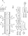
- FIG. 2 there is shown a microwave tomography steam wetness measurement system 100 according to illustrative aspects for measuring the wetness of steam 104 (e.g., steam 34, FIG. 1 ) passing through a pipe 102.
- the pipe 102 may include any hollow structure capable of conveying a supply of wet steam 104.
- Wetness measurements of the steam 104 are performed at at least two different cross-sections (e.g., cross-sections A--A and B--B in FIG. 2 ) along the pipe 102 using a plurality of sets 106 of microwave sensors 108.
- the microwave sensors 108 in each set 106 are distributed (e.g., equidistant) about the circumference of the pipe 102.
- the microwave sensors 108 can be flush to the pipe or extend into the interior of the pipe 102 beyond, and isolated from, the thin film 110 of liquid water flowing along the interior surfaces of the pipe 102.
- Film measurements (e.g., thickness, film velocity) of the film 110 are performed at at least one location (e.g., location X in FIG. 2 ) using a set of electrodes 112 to determine the thickness of the film 110 and, over time, the flow velocity of the film 110.
- Microwaves are generated by a variable frequency microwave source 114, and are routed into the pipe 102 via a waveguide 116.
- Microwave sensors 108 are capable of monitoring the wetness of the steam 104 in real time. However, for accurate measurement microwave sensors 108 require calibration and cannot determine the effects of the film 110 on measured data. To obviate these issues, according to embodiments, the microwave tomography steam wetness measurement system 100 includes a microwave phase shift measurement device 120 for self-calibrating the microwave sensors 108, and a film measurement system 122 for determining, using conductivity data from the set of electrodes 112, the thickness and flow velocity of the film 110.
- microwave phase shift measurements are also too slow for inline steam wetness measurements, as such measurements involve scanning over a range of frequencies to determine the lowest destructive frequency.
- microwave phase shift measurements are used to self-calibrate the microwave sensors 108.
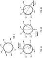
- FIG. 3 A cross-sectional view taken along line A--A of FIG. 2 is shown in FIG. 3 .
- a plurality of microwave sensors 108 are arranged about the circumference of the pipe 102.
- Microwave phase shift measurements use two separate microwave signals travelling different lengths, within the steam 104, to determine the frequency for a phase change of ⁇ .
- a phase change equal to ⁇ will cause destructive interference as the signals will be equal and opposite.
- the frequency is changed until a frequency is found where the phase change is constant.
- FIGS. 4A, 4B, and 4C Examples of measurement paths of microwave signals 124 to the microwave sensors 108 depicted in FIG. 3 are shown in FIGS. 4A, 4B, and 4C .
- Multiple phase shift and attenuation measurements across the pipe 102 are taken individually in sequence. Multiple independent phase shift and attenuation measurements are possible for the six sensor system shown in FIG. 3 , with three of them shown in FIGS. 4A, 4B, and 4C .
- the electrical permittivity of the steam 104 can be found in a known manner by determining the lowest frequency at which destructive interference occurs.
- Calibration of the microwave sensors 108 uses phase shift and attenuation measurements taken at a range of steam 104 wetness to develop a prediction curve; with future phase shift and attenuation measurements fitted to this curve to determine the wetness of the steam 104.
- wetness measurements of the steam 104 are performed at at least two different cross-sections (e.g., cross-sections A--A and B--B in FIG. 2 ) along the pipe 102 using a plurality of sets 106 of microwave sensors 108.
- the microwave sensors 108 are microwave transducers. Microwave signals of at least one frequency are directed through the steam 104 in the pipe and are detected by the microwave sensors 108.
- a void fraction analysis 126 is performed in a known manner on the data obtained by the microwave sensors 108 to determine the void fraction of the steam 104 at each cross-section AA and B--B within the pipe 102.
- the film measurement system 122 receives electrical conductivity data of the film 110 from the set of electrodes 112.
- the electrical conductivity data may include, for example, the capacitance or resistance of the film 110, dependent on the type of conductivity measured.
- the film measurement system 122 calculates the thickness of the film 110 in a known manner. Analysis of the film thickness over time at one or more locations along the pipe 102 may be used to determine the velocity of the film 110 flowing through the pipe 102.
- the film measurement data (film thickness and flow velocity of the film 110) provided by the film measurement system 122 and void fraction data provided by the void fraction analysis are then analyzed 128 to account for the effect of the film 110 on the void fraction data provided by the void fraction analysis 126. Based on the analysis 128, adjustments are made to the components of the microwave tomography steam wetness measurement system 100 and/or the void fraction data to increase the accuracy of the steam wetness measurement. This allows a more accurate separation of measurement data associated with the film 110 and the steam 104.
- the resultant data at each cross-section A--A and B--B within the pipe 102 is cross-correlated 130 to determine a steam wetness measurement 132.
- FIG. 5 depicts a process for microwave tomography steam wetness measurement according to various embodiments.
- the phase shift measurement device 122 receives sensor data from the plurality of sets 106 of microwave sensors 108 and, based on the received sensor data, calibrates the microwave sensors 108.
- the film measurement system 122 determines the thickness and flow velocity of the film 110 in the pipe 102. S2 may be performed before, during, or after S1.
- microwave sensor data from the now calibrated microwave sensors 108 is obtained at a plurality of locations within the pipe 102 and, at S4, the microwave sensor data is analyzed to determine void fraction data of the steam 104 at each of the plurality of locations.
- an analysis 128 is performed to determine the effect of the film 110 on the void fraction data to provide modified void fraction data.
- the modified void fraction data for the plurality of locations is cross-correlated 130, and a steam wetness measurement 132 of the steam 104 is determined at S7.
- the microwave tomography steam wetness measurement system 100 provides high speed, real time, wet steam measurement, for application in pipework.
- the microwave tomography steam wetness measurement system 100 is suitable for retrofit and new builds.
- components described as being “coupled” to one another can be joined along one or more interfaces.
- these interfaces can include junctions between distinct components, and in other cases, these interfaces can include a solidly and/or integrally formed interconnection. That is, in some cases, components that are "coupled” to one another can be simultaneously formed to define a single continuous member.
- these coupled components can be formed as separate members and be subsequently joined through known processes (e.g., fastening, ultrasonic welding, bonding).
- Fluidly coupled refers to a coupling through which a fluid can flow.
Landscapes
- Engineering & Computer Science (AREA)
- Chemical & Material Sciences (AREA)
- Mechanical Engineering (AREA)
- General Engineering & Computer Science (AREA)
- Physics & Mathematics (AREA)
- Combustion & Propulsion (AREA)
- Life Sciences & Earth Sciences (AREA)
- Health & Medical Sciences (AREA)
- Electromagnetism (AREA)
- Analytical Chemistry (AREA)
- Biochemistry (AREA)
- General Health & Medical Sciences (AREA)
- General Physics & Mathematics (AREA)
- Immunology (AREA)
- Pathology (AREA)
- Investigating Or Analyzing Materials By The Use Of Electric Means (AREA)
- Investigating Or Analyzing Materials By The Use Of Fluid Adsorption Or Reactions (AREA)
Applications Claiming Priority (2)
| Application Number | Priority Date | Filing Date | Title |
|---|---|---|---|
| US15/358,855 US10234405B2 (en) | 2016-11-22 | 2016-11-22 | Steam wetness measurement with microwave tomography |
| PCT/US2017/059033 WO2018097933A1 (en) | 2016-11-22 | 2017-10-30 | Steam wetness measurement with microwave tomography |
Publications (3)
| Publication Number | Publication Date |
|---|---|
| EP3545285A1 EP3545285A1 (en) | 2019-10-02 |
| EP3545285A4 EP3545285A4 (en) | 2020-09-02 |
| EP3545285B1 true EP3545285B1 (en) | 2022-07-20 |
Family
ID=62146932
Family Applications (1)
| Application Number | Title | Priority Date | Filing Date |
|---|---|---|---|
| EP17872987.7A Active EP3545285B1 (en) | 2016-11-22 | 2017-10-30 | Steam wetness measurement with microwave tomography |
Country Status (6)
| Country | Link |
|---|---|
| US (1) | US10234405B2 (pl) |
| EP (1) | EP3545285B1 (pl) |
| CN (1) | CN109964117B (pl) |
| HU (1) | HUE059786T2 (pl) |
| PL (1) | PL3545285T3 (pl) |
| WO (1) | WO2018097933A1 (pl) |
Family Cites Families (17)
| Publication number | Priority date | Publication date | Assignee | Title |
|---|---|---|---|---|
| US6674054B2 (en) * | 2001-04-26 | 2004-01-06 | Phifer-Smith Corporation | Method and apparatus for heating a gas-solvent solution |
| WO2005010468A2 (en) * | 2003-07-15 | 2005-02-03 | Cidra Corporation | A configurable multi-function flow measurement apparatus having an array of sensors |
| WO2007009097A1 (en) * | 2005-07-13 | 2007-01-18 | Cidra Corporation | Method and apparatus for measuring parameters of a fluid flow using an array of sensors |
| NO326977B1 (no) * | 2006-05-02 | 2009-03-30 | Multi Phase Meters As | Fremgangsmåte og innretning for måling av konduktiviteten av vannfraksjonen i en våtgass |
| NO324812B1 (no) * | 2006-05-05 | 2007-12-10 | Multi Phase Meters As | Fremgangsmåte og innretning for tomografiske multifasestrømningsmålinger |
| US9163955B2 (en) * | 2012-04-25 | 2015-10-20 | Eastman Kodak Company | Electronic sensing system with environmental sensor patches |
| CN101799436B (zh) * | 2010-03-18 | 2012-07-25 | 中国农业大学 | 基于相位检测的土壤水分、电导率测量仪及其测量方法 |
| US8791707B2 (en) * | 2010-07-19 | 2014-07-29 | Iowa State University Research Foundation, Inc. | Concentric coplanar capacitive sensor system with quantitative model |
| US9909910B2 (en) | 2012-10-23 | 2018-03-06 | Cidra Corporate Services Inc. | Tomographic and sonar-based processing using electrical probing of a flowing fluid to determine flow rate |
| WO2014066978A1 (en) * | 2012-10-29 | 2014-05-08 | MEMS-Vision International Inc. | Methods and systems for humidity and pressure sensor overlay integration with electronics |
| CN103940851B (zh) | 2014-04-04 | 2016-04-27 | 西安交通大学 | 基于微波加热的流动湿蒸汽湿度测量探针及其测量方法 |
| KR102238937B1 (ko) * | 2014-07-22 | 2021-04-09 | 주식회사 키 파운드리 | 배선 사이의 중공에 형성된 습도 센서 및 그 제조 방법 |
| EP2985597B1 (en) * | 2014-08-14 | 2021-08-25 | General Electric Technology GmbH | Steam wetness measurement device |
| CN105974346B (zh) * | 2016-04-28 | 2021-04-23 | 中国科学院电子学研究所 | 一种静电场传感器的自动化标定装置及标定方法 |
| CN105928954B (zh) * | 2016-04-29 | 2018-10-26 | 华北电力大学(保定) | 一种双模双通道汽轮机蒸汽湿度测量系统和方法 |
| CN105716548B (zh) | 2016-04-29 | 2018-05-18 | 华北电力大学(保定) | 微波微扰法测量湿度传感器内壁水膜厚度的系统和方法 |
| CN106125028B (zh) * | 2016-06-14 | 2018-12-18 | 中国科学院电子学研究所 | 电场传感器动态测试标定装置 |
-
2016
- 2016-11-22 US US15/358,855 patent/US10234405B2/en active Active
-
2017
- 2017-10-30 EP EP17872987.7A patent/EP3545285B1/en active Active
- 2017-10-30 PL PL17872987.7T patent/PL3545285T3/pl unknown
- 2017-10-30 WO PCT/US2017/059033 patent/WO2018097933A1/en not_active Ceased
- 2017-10-30 HU HUE17872987A patent/HUE059786T2/hu unknown
- 2017-10-30 CN CN201780072198.6A patent/CN109964117B/zh active Active
Non-Patent Citations (1)
| Title |
|---|
| JU Y ET AL: "A METHOD OF THE MEASUREMENT OF MOISTURE IN IC PACKAGES USING MICROWAVES", IEEE TRANSACTIONS ON ELECTRONICS PACKAGING MANUFACTURING, IEEE SERVICE CENTER, PISCATAWAY, NJ, US, vol. 26, no. 3, 1 July 2003 (2003-07-01), pages 228 - 231, XP001192664, ISSN: 1523-334X, DOI: 10.1109/TEPM.2003.820808 * |
Also Published As
| Publication number | Publication date |
|---|---|
| US10234405B2 (en) | 2019-03-19 |
| PL3545285T3 (pl) | 2022-09-26 |
| EP3545285A1 (en) | 2019-10-02 |
| CN109964117A (zh) | 2019-07-02 |
| CN109964117B (zh) | 2022-07-15 |
| US20180143146A1 (en) | 2018-05-24 |
| EP3545285A4 (en) | 2020-09-02 |
| HUE059786T2 (hu) | 2022-12-28 |
| WO2018097933A1 (en) | 2018-05-31 |
Similar Documents
| Publication | Publication Date | Title |
|---|---|---|
| US10101186B2 (en) | Method and measuring apparatus for determining specific quantities for gas quality | |
| US3950985A (en) | Method of and apparatus for monitoring the durability of components of thermal power plants | |
| US11193854B2 (en) | Estimating fluid parameter | |
| Kergourlay et al. | Experimental investigation of the 3D unsteady flow field downstream of axial fans | |
| Lenherr et al. | High temperature fast response aerodynamic probe | |
| EP3545285B1 (en) | Steam wetness measurement with microwave tomography | |
| Crowther et al. | An evaluation of the mass and power scaling of synthetic jet actuator flow control technology for civil transport aircraft applications | |
| Van Fossen et al. | Augmentation of stagnation region heat transfer due to turbulence from a DLN can combustor | |
| Andraka et al. | Heat-transfer distribution around a cylinder in pulsating crossflow | |
| CN103838961A (zh) | 超超临界汽轮机转子三维温度和热应力实时监测方法 | |
| Mersinligil et al. | Unsteady pressure measurements with a fast response cooled probe in high temperature gas turbine environments | |
| Thurman et al. | Inlet Turbulence and Length Scale Measurements in a Large Scale Transonic Turbine Cascade | |
| Diller et al. | Time-resolved heat transfer and skin friction measurements in unsteady flow | |
| Mersinligil et al. | First unsteady pressure measurements with a fast response cooled total pressure probe in high temperature gas turbine environments | |
| Sukhinets et al. | Features of the use of jet-acoustic sensors for dynamic measurements of gas temperature in gas turbine engines | |
| Mansour | A 48kHz bandwidth, 1.8 mm diameter entropy probe for aerothermal loss measurements in turbomachinery flows | |
| Singh et al. | Investigation of a high-pressure turbine stage in a high-speed rotating transient test facility for rotor tip study and a parametric study for improved heat transfer calculation | |
| Wu et al. | Investigation of instability waves in a Mach 3 laminar boundary layer | |
| Veley et al. | Unsteady Flow Measurements in a Low Pressure Turbine Passage using Surface Mounted Thin Film Sensors | |
| Beard et al. | Deepanshu Singh | |
| KR900005477B1 (ko) | 전기 가열된 증기질 측정기 및 측정방법 | |
| Ciocan et al. | Wall friction measurements: application in a Francis turbine cone | |
| Mikulla et al. | Turbulence stress measurements in a nonadiabatic hypersonic boundarylayer | |
| ZERKLE et al. | The influence of freestream turbulence and pressure gradient on heattransfer to gas turbine airfoils | |
| Johnson et al. | Measurements with a heat flux microsensor deposited on a transonic turbine blade |
Legal Events
| Date | Code | Title | Description |
|---|---|---|---|
| STAA | Information on the status of an ep patent application or granted ep patent |
Free format text: STATUS: THE INTERNATIONAL PUBLICATION HAS BEEN MADE |
|
| PUAI | Public reference made under article 153(3) epc to a published international application that has entered the european phase |
Free format text: ORIGINAL CODE: 0009012 |
|
| STAA | Information on the status of an ep patent application or granted ep patent |
Free format text: STATUS: REQUEST FOR EXAMINATION WAS MADE |
|
| 17P | Request for examination filed |
Effective date: 20190515 |
|
| AK | Designated contracting states |
Kind code of ref document: A1 Designated state(s): AL AT BE BG CH CY CZ DE DK EE ES FI FR GB GR HR HU IE IS IT LI LT LU LV MC MK MT NL NO PL PT RO RS SE SI SK SM TR |
|
| AX | Request for extension of the european patent |
Extension state: BA ME |
|
| DAV | Request for validation of the european patent (deleted) | ||
| DAX | Request for extension of the european patent (deleted) | ||
| A4 | Supplementary search report drawn up and despatched |
Effective date: 20200730 |
|
| RIC1 | Information provided on ipc code assigned before grant |
Ipc: G01N 22/04 20060101AFI20200724BHEP |
|
| GRAP | Despatch of communication of intention to grant a patent |
Free format text: ORIGINAL CODE: EPIDOSNIGR1 |
|
| STAA | Information on the status of an ep patent application or granted ep patent |
Free format text: STATUS: GRANT OF PATENT IS INTENDED |
|
| INTG | Intention to grant announced |
Effective date: 20220208 |
|
| GRAS | Grant fee paid |
Free format text: ORIGINAL CODE: EPIDOSNIGR3 |
|
| GRAA | (expected) grant |
Free format text: ORIGINAL CODE: 0009210 |
|
| STAA | Information on the status of an ep patent application or granted ep patent |
Free format text: STATUS: THE PATENT HAS BEEN GRANTED |
|
| AK | Designated contracting states |
Kind code of ref document: B1 Designated state(s): AL AT BE BG CH CY CZ DE DK EE ES FI FR GB GR HR HU IE IS IT LI LT LU LV MC MK MT NL NO PL PT RO RS SE SI SK SM TR |
|
| REG | Reference to a national code |
Ref country code: CH Ref legal event code: EP |
|
| REG | Reference to a national code |
Ref country code: DE Ref legal event code: R096 Ref document number: 602017059747 Country of ref document: DE |
|
| REG | Reference to a national code |
Ref country code: AT Ref legal event code: REF Ref document number: 1505829 Country of ref document: AT Kind code of ref document: T Effective date: 20220815 |
|
| REG | Reference to a national code |
Ref country code: FI Ref legal event code: FGE |
|
| REG | Reference to a national code |
Ref country code: IE Ref legal event code: FG4D |
|
| REG | Reference to a national code |
Ref country code: SE Ref legal event code: TRGR |
|
| REG | Reference to a national code |
Ref country code: LT Ref legal event code: MG9D |
|
| REG | Reference to a national code |
Ref country code: NL Ref legal event code: MP Effective date: 20220720 |
|
| REG | Reference to a national code |
Ref country code: HU Ref legal event code: AG4A Ref document number: E059786 Country of ref document: HU |
|
| PG25 | Lapsed in a contracting state [announced via postgrant information from national office to epo] |
Ref country code: RS Free format text: LAPSE BECAUSE OF FAILURE TO SUBMIT A TRANSLATION OF THE DESCRIPTION OR TO PAY THE FEE WITHIN THE PRESCRIBED TIME-LIMIT Effective date: 20220720 Ref country code: PT Free format text: LAPSE BECAUSE OF FAILURE TO SUBMIT A TRANSLATION OF THE DESCRIPTION OR TO PAY THE FEE WITHIN THE PRESCRIBED TIME-LIMIT Effective date: 20221121 Ref country code: NO Free format text: LAPSE BECAUSE OF FAILURE TO SUBMIT A TRANSLATION OF THE DESCRIPTION OR TO PAY THE FEE WITHIN THE PRESCRIBED TIME-LIMIT Effective date: 20221020 Ref country code: NL Free format text: LAPSE BECAUSE OF FAILURE TO SUBMIT A TRANSLATION OF THE DESCRIPTION OR TO PAY THE FEE WITHIN THE PRESCRIBED TIME-LIMIT Effective date: 20220720 Ref country code: LV Free format text: LAPSE BECAUSE OF FAILURE TO SUBMIT A TRANSLATION OF THE DESCRIPTION OR TO PAY THE FEE WITHIN THE PRESCRIBED TIME-LIMIT Effective date: 20220720 Ref country code: LT Free format text: LAPSE BECAUSE OF FAILURE TO SUBMIT A TRANSLATION OF THE DESCRIPTION OR TO PAY THE FEE WITHIN THE PRESCRIBED TIME-LIMIT Effective date: 20220720 Ref country code: ES Free format text: LAPSE BECAUSE OF FAILURE TO SUBMIT A TRANSLATION OF THE DESCRIPTION OR TO PAY THE FEE WITHIN THE PRESCRIBED TIME-LIMIT Effective date: 20220720 |
|
| REG | Reference to a national code |
Ref country code: AT Ref legal event code: MK05 Ref document number: 1505829 Country of ref document: AT Kind code of ref document: T Effective date: 20220720 |
|
| PG25 | Lapsed in a contracting state [announced via postgrant information from national office to epo] |
Ref country code: IS Free format text: LAPSE BECAUSE OF FAILURE TO SUBMIT A TRANSLATION OF THE DESCRIPTION OR TO PAY THE FEE WITHIN THE PRESCRIBED TIME-LIMIT Effective date: 20221120 Ref country code: HR Free format text: LAPSE BECAUSE OF FAILURE TO SUBMIT A TRANSLATION OF THE DESCRIPTION OR TO PAY THE FEE WITHIN THE PRESCRIBED TIME-LIMIT Effective date: 20220720 Ref country code: GR Free format text: LAPSE BECAUSE OF FAILURE TO SUBMIT A TRANSLATION OF THE DESCRIPTION OR TO PAY THE FEE WITHIN THE PRESCRIBED TIME-LIMIT Effective date: 20221021 |
|
| REG | Reference to a national code |
Ref country code: DE Ref legal event code: R097 Ref document number: 602017059747 Country of ref document: DE |
|
| PG25 | Lapsed in a contracting state [announced via postgrant information from national office to epo] |
Ref country code: SM Free format text: LAPSE BECAUSE OF FAILURE TO SUBMIT A TRANSLATION OF THE DESCRIPTION OR TO PAY THE FEE WITHIN THE PRESCRIBED TIME-LIMIT Effective date: 20220720 Ref country code: RO Free format text: LAPSE BECAUSE OF FAILURE TO SUBMIT A TRANSLATION OF THE DESCRIPTION OR TO PAY THE FEE WITHIN THE PRESCRIBED TIME-LIMIT Effective date: 20220720 Ref country code: DK Free format text: LAPSE BECAUSE OF FAILURE TO SUBMIT A TRANSLATION OF THE DESCRIPTION OR TO PAY THE FEE WITHIN THE PRESCRIBED TIME-LIMIT Effective date: 20220720 Ref country code: CZ Free format text: LAPSE BECAUSE OF FAILURE TO SUBMIT A TRANSLATION OF THE DESCRIPTION OR TO PAY THE FEE WITHIN THE PRESCRIBED TIME-LIMIT Effective date: 20220720 Ref country code: AT Free format text: LAPSE BECAUSE OF FAILURE TO SUBMIT A TRANSLATION OF THE DESCRIPTION OR TO PAY THE FEE WITHIN THE PRESCRIBED TIME-LIMIT Effective date: 20220720 |
|
| REG | Reference to a national code |
Ref country code: DE Ref legal event code: R119 Ref document number: 602017059747 Country of ref document: DE |
|
| PLBE | No opposition filed within time limit |
Free format text: ORIGINAL CODE: 0009261 |
|
| STAA | Information on the status of an ep patent application or granted ep patent |
Free format text: STATUS: NO OPPOSITION FILED WITHIN TIME LIMIT |
|
| PG25 | Lapsed in a contracting state [announced via postgrant information from national office to epo] |
Ref country code: SK Free format text: LAPSE BECAUSE OF FAILURE TO SUBMIT A TRANSLATION OF THE DESCRIPTION OR TO PAY THE FEE WITHIN THE PRESCRIBED TIME-LIMIT Effective date: 20220720 Ref country code: MC Free format text: LAPSE BECAUSE OF FAILURE TO SUBMIT A TRANSLATION OF THE DESCRIPTION OR TO PAY THE FEE WITHIN THE PRESCRIBED TIME-LIMIT Effective date: 20220720 Ref country code: EE Free format text: LAPSE BECAUSE OF FAILURE TO SUBMIT A TRANSLATION OF THE DESCRIPTION OR TO PAY THE FEE WITHIN THE PRESCRIBED TIME-LIMIT Effective date: 20220720 |
|
| REG | Reference to a national code |
Ref country code: CH Ref legal event code: PL |
|
| REG | Reference to a national code |
Ref country code: BE Ref legal event code: MM Effective date: 20221031 |
|
| 26N | No opposition filed |
Effective date: 20230421 |
|
| P01 | Opt-out of the competence of the unified patent court (upc) registered |
Effective date: 20230523 |
|
| PG25 | Lapsed in a contracting state [announced via postgrant information from national office to epo] |
Ref country code: LU Free format text: LAPSE BECAUSE OF NON-PAYMENT OF DUE FEES Effective date: 20221030 Ref country code: AL Free format text: LAPSE BECAUSE OF FAILURE TO SUBMIT A TRANSLATION OF THE DESCRIPTION OR TO PAY THE FEE WITHIN THE PRESCRIBED TIME-LIMIT Effective date: 20220720 |
|
| PG25 | Lapsed in a contracting state [announced via postgrant information from national office to epo] |
Ref country code: LI Free format text: LAPSE BECAUSE OF NON-PAYMENT OF DUE FEES Effective date: 20221031 Ref country code: DE Free format text: LAPSE BECAUSE OF NON-PAYMENT OF DUE FEES Effective date: 20230503 Ref country code: CH Free format text: LAPSE BECAUSE OF NON-PAYMENT OF DUE FEES Effective date: 20221031 |
|
| PG25 | Lapsed in a contracting state [announced via postgrant information from national office to epo] |
Ref country code: SI Free format text: LAPSE BECAUSE OF FAILURE TO SUBMIT A TRANSLATION OF THE DESCRIPTION OR TO PAY THE FEE WITHIN THE PRESCRIBED TIME-LIMIT Effective date: 20220720 |
|
| PG25 | Lapsed in a contracting state [announced via postgrant information from national office to epo] |
Ref country code: BE Free format text: LAPSE BECAUSE OF NON-PAYMENT OF DUE FEES Effective date: 20221031 |
|
| PG25 | Lapsed in a contracting state [announced via postgrant information from national office to epo] |
Ref country code: IE Free format text: LAPSE BECAUSE OF NON-PAYMENT OF DUE FEES Effective date: 20221030 |
|
| REG | Reference to a national code |
Ref country code: HU Ref legal event code: GB9C Owner name: GENERAL ELECTRIC TECHNOLOGY GMBH, CH Free format text: FORMER OWNER(S): GENERAL ELECTRIC COMPANY, US |
|
| PG25 | Lapsed in a contracting state [announced via postgrant information from national office to epo] |
Ref country code: CY Free format text: LAPSE BECAUSE OF FAILURE TO SUBMIT A TRANSLATION OF THE DESCRIPTION OR TO PAY THE FEE WITHIN THE PRESCRIBED TIME-LIMIT Effective date: 20220720 |
|
| REG | Reference to a national code |
Ref country code: FI Ref legal event code: PCE Owner name: GENERAL ELECTRIC TECHNOLOGY GMBH |
|
| REG | Reference to a national code |
Ref country code: GB Ref legal event code: 732E Free format text: REGISTERED BETWEEN 20240502 AND 20240508 |
|
| PG25 | Lapsed in a contracting state [announced via postgrant information from national office to epo] |
Ref country code: MK Free format text: LAPSE BECAUSE OF FAILURE TO SUBMIT A TRANSLATION OF THE DESCRIPTION OR TO PAY THE FEE WITHIN THE PRESCRIBED TIME-LIMIT Effective date: 20220720 |
|
| PG25 | Lapsed in a contracting state [announced via postgrant information from national office to epo] |
Ref country code: BG Free format text: LAPSE BECAUSE OF FAILURE TO SUBMIT A TRANSLATION OF THE DESCRIPTION OR TO PAY THE FEE WITHIN THE PRESCRIBED TIME-LIMIT Effective date: 20220720 |
|
| PG25 | Lapsed in a contracting state [announced via postgrant information from national office to epo] |
Ref country code: MT Free format text: LAPSE BECAUSE OF FAILURE TO SUBMIT A TRANSLATION OF THE DESCRIPTION OR TO PAY THE FEE WITHIN THE PRESCRIBED TIME-LIMIT Effective date: 20220720 |
|
| REG | Reference to a national code |
Ref country code: FI Ref legal event code: PCE Owner name: ARABELLE TECHNOLOGIES |
|
| REG | Reference to a national code |
Ref country code: HU Ref legal event code: GB9C Owner name: ARABELLE TECHNOLOGIES, FR Free format text: FORMER OWNER(S): GENERAL ELECTRIC COMPANY, US; GENERAL ELECTRIC TECHNOLOGY GMBH, CH |
|
| REG | Reference to a national code |
Ref country code: GB Ref legal event code: 732E Free format text: REGISTERED BETWEEN 20250213 AND 20250219 |
|
| REG | Reference to a national code |
Ref country code: HU Ref legal event code: GB9C Owner name: ARABELLE SOLUTIONS FRANCE, FR Free format text: FORMER OWNER(S): GENERAL ELECTRIC COMPANY, US; ARABELLE TECHNOLOGIES, FR; GENERAL ELECTRIC TECHNOLOGY GMBH, CH |
|
| REG | Reference to a national code |
Ref country code: GB Ref legal event code: 732E Free format text: REGISTERED BETWEEN 20250619 AND 20250625 |
|
| PGFP | Annual fee paid to national office [announced via postgrant information from national office to epo] |
Ref country code: FI Payment date: 20250923 Year of fee payment: 9 |
|
| PGFP | Annual fee paid to national office [announced via postgrant information from national office to epo] |
Ref country code: PL Payment date: 20250924 Year of fee payment: 9 Ref country code: IT Payment date: 20250923 Year of fee payment: 9 |
|
| PGFP | Annual fee paid to national office [announced via postgrant information from national office to epo] |
Ref country code: GB Payment date: 20250923 Year of fee payment: 9 |
|
| PGFP | Annual fee paid to national office [announced via postgrant information from national office to epo] |
Ref country code: FR Payment date: 20250924 Year of fee payment: 9 |
|
| PGFP | Annual fee paid to national office [announced via postgrant information from national office to epo] |
Ref country code: SE Payment date: 20250923 Year of fee payment: 9 |
|
| PGFP | Annual fee paid to national office [announced via postgrant information from national office to epo] |
Ref country code: HU Payment date: 20251029 Year of fee payment: 9 |
|
| PGFP | Annual fee paid to national office [announced via postgrant information from national office to epo] |
Ref country code: TR Payment date: 20251001 Year of fee payment: 9 |
|
| REG | Reference to a national code |
Ref country code: FI Ref legal event code: PCE Owner name: ARABELLE SOLUTIONS FRANCE, FR |