EP3545275B1 - Integriertes system und verfahren zur messung von verformungen und/oder spannungen bei eindimensionalen elementen - Google Patents
Integriertes system und verfahren zur messung von verformungen und/oder spannungen bei eindimensionalen elementen Download PDFInfo
- Publication number
- EP3545275B1 EP3545275B1 EP17817878.6A EP17817878A EP3545275B1 EP 3545275 B1 EP3545275 B1 EP 3545275B1 EP 17817878 A EP17817878 A EP 17817878A EP 3545275 B1 EP3545275 B1 EP 3545275B1
- Authority
- EP
- European Patent Office
- Prior art keywords
- cavity
- structural element
- fluid
- measuring
- temperature
- Prior art date
- Legal status (The legal status is an assumption and is not a legal conclusion. Google has not performed a legal analysis and makes no representation as to the accuracy of the status listed.)
- Active
Links
Images


Classifications
-
- G—PHYSICS
- G01—MEASURING; TESTING
- G01L—MEASURING FORCE, STRESS, TORQUE, WORK, MECHANICAL POWER, MECHANICAL EFFICIENCY, OR FLUID PRESSURE
- G01L1/00—Measuring force or stress, in general
- G01L1/02—Measuring force or stress, in general by hydraulic or pneumatic means
-
- G—PHYSICS
- G01—MEASURING; TESTING
- G01L—MEASURING FORCE, STRESS, TORQUE, WORK, MECHANICAL POWER, MECHANICAL EFFICIENCY, OR FLUID PRESSURE
- G01L9/00—Measuring steady of quasi-steady pressure of fluid or fluent solid material by electric or magnetic pressure-sensitive elements; Transmitting or indicating the displacement of mechanical pressure-sensitive elements, used to measure the steady or quasi-steady pressure of a fluid or fluent solid material, by electric or magnetic means
- G01L9/0041—Transmitting or indicating the displacement of flexible diaphragms
- G01L9/0042—Constructional details associated with semiconductive diaphragm sensors, e.g. etching, or constructional details of non-semiconductive diaphragms
- G01L9/0045—Diaphragm associated with a buried cavity
Definitions
- the present invention is generally in the field of measurements of forces, stresses, deformations, etc.; in particular, the invention refers to an integrated system and a method for measuring the deformation and/or stress in structural elements adapted to be incorporated in building constructions.
- the measurement of deformations in structural elements is generally carried out using electrical strain gauges, electrical and mechanical comparators, vibrating wire strain gauges or fiber optics with Bragg gratings.
- the aim is to measure the average deformation with respect to a measurement base on the order of a few millimeters (electrical strain gauges) or up to several tens of centimeters (vibrating wire strain gauges).
- Such instruments may be applied to the external surface of the elements to be measured for deformation, or they may be inserted inside the structures, as in the case of civil structures made of reinforced concrete. In the latter case, the devices are positioned before the casting of the concrete, thus becoming embedded within the elements themselves.
- Instruments such as electrical strain gauges may be applied both on the outside and the inside of the structures. Traditionally, when placed internally, they are bonded to the metal reinforcement bars. On the other hand, if applied to the surface, they are bonded directly to the concrete.
- Optical fibers are also traditionally used as a system for measuring deformation, and may be positioned both internally and externally in reinforced concrete structures.
- Some known solutions include the use of fiber optics with Bragg gratings housed and bonded inside a seat formed along the longitudinal ribs of steel bars.
- optical fibers are fastened to the reinforcement grating and embedded in the casting, or are bonded externally to the element the deformations of, which are to be measured.
- the measurements made by such devices are related to respective bases of measurement, i.e. to pairs of spaced application points.
- the distance between the bases of measurement is usually on the order of centimeters, and the elongation value read is divided by the distance between the bases to provide the average deformation.
- Vibrating wire strain gauges may be used both as external and internal systems and exploit the variation of the vibration frequency of a component of the system to trace the elongation between two fixed points (bases) and thus an average deformation in reference to such bases.
- the measurement of deformation is more accurate and, in some respects, more useful for structural monitoring, the shorter the length of the measurement ⁇ base with respect to the structural dimensions.
- devices such as electrical strain gauges, if applied on the surfaces of interfaces between different materials (e.g. on the outer surface of reinforcing bars in reinforced concrete elements), may give rise to insignificant measurements also due to local cracks and sliding, as well as to alteration of the adhesion between the steel and concrete locally.
- the monitoring of the steel reinforcement elements allows deformations/stresses, both in compression and in tension, to be detected, as opposed to what is possible in the case of monitoring on concrete, which may crack if it is stressed in tension beyond its strength limit. In the latter case, information about deformation/stress would be lost. This represents a major benefit for monitoring systems applied to steel elements.
- the metallic reinforcements are a natural location for monitoring devices.
- any measurement will be affected by intrinsic variability due to such heterogeneity.
- delayed deformations of the concrete, evaluated locally may result in measurements with wide dispersion. Steel elements are much more homogeneous; they do not directly suffer from rheological effects, and therefore the accuracy, linearity and repeatability of the measurements are decidedly greater.
- built-in devices that measure deformations in concrete may be easily damaged by installation and casting operations.
- stress/force measuring systems according to the prior art have dimensions that are often unsuitable for the local detection of deformations/stresses, as well as have, in most cases, a significant unit cost.
- a measurement system of the stress loaded on a structural element is considered, wherein such measurement is performed by reading the variation of physical parameters within a longitudinal cavity formed in the body of the structural element and filled with an incompressible fluid.
- An example of such a measurement system is known from the document DE 10 2013 012690 A1 .
- this system allows the force acting on the pin of a pulley, on which a cable for lifting a load is wound, to be evaluated through the pressure variation in the cavity induced by the bending of the pin.
- the cavity is made with a parallel axis that is not coincident with respect to the longitudinal axis of the pin for a length substantially comparable to the length of the pin itself. In fact, if the axis of the cavity coincides with that of the pin, a correct measurement of the force applied thereon cannot be obtained, a measurement that becomes all the more significant, the greater the length of the cavity.
- a system which is configured in such a way is not applicable to structural elements for building constructions, which have a substantially single-dimensional shape (in the sense that the longitudinal dimension is decisively dominant over the transverse dimension, even by tens of times), where the pin of the example of the prior art is a deep object, which is not meant to be embedded in the structural element of a construction.
- the pin of the example of the prior art is a deep object, which is not meant to be embedded in the structural element of a construction.
- the eccentric position of such cavity, with respect to the longitudinal axis of the structural element would impair the measurement of the deformations, as it would suffer unwanted flexural contributions.
- One object of the present invention is to remedy the aforementioned problems which are solved by an integrated measuring system as defined in claim 1 and by a corresponding method as defined in claim 8.
- a system for measuring a deformation of a structural element suitable to be incorporated into a building construction comprises a cavity oriented perpendicular to a central longitudinal axis of the structural element.
- Such cavity is filled with a compressible fluid and sealed, so that when the structural element is affected by an action F along its longitudinal axis (an action that may be mechanical or thermal, such as a longitudinal tensile action, or an expansion due to an increase in temperature), the cavity undergoes a deformation, which causes a variation in the pressure and temperature of the fluid inside.
- an action F along its longitudinal axis an action that may be mechanical or thermal, such as a longitudinal tensile action, or an expansion due to an increase in temperature
- the cavity undergoes a deformation, which causes a variation in the pressure and temperature of the fluid inside.
- a plurality of measurement systems may also be carried out in a practical and convenient manner, since it is sufficient to make simple transverse holes in the structural element, while the solution adopted in the prior art would be much more complex to achieve, as it requires making a longitudinal cavity along a substantially single-dimensional element, a cavity moreover eccentric with respect to the longitudinal axis thereof.
- a generic action in the example shown, a tensile stress
- the structural element in the example shown, a substantially one -dimensional element, with a constant cross-section along its own axis
- Deformations due to other actions acting along the remaining directions are generally added to the deformation in the axial direction, so as to formulate a three-dimensional deformation.
- the volume variation of the cavity is related to the pressure variation and the temperature of the fluid contained therein.
- the initial fluid pressure and temperature and the variations thereof are measured by means of respective devices.
- Pressure and temperature measurements allow the volume variation of the cavity to be estimated and correlated with the deforming state of the element by providing a measurement thereof.
- the system may estimate the internal stresses by reading the pressure variation in the presence of constant volume (effect of a temperature variation) and by knowing the physical characteristics of the material of the structural element.
- zones with deformation/stress spikes form around the cavity, which affect very limited areas and wherein plastic deformations may occur; a negligible influence on the volume variation results, in comparison with the value of the average deformation calculated on the section of the structural element, appropriately removed from the section of the cavity. Deformations beyond the elastic limit of the material lead to non-linearity of the system's response.
- the graph in figure 3 shows the results of a first experiment on steel elements for reinforced concrete. One may see that the results in figure 3 show a good linearity and a lack of hysteresis.
- the graph shows the pressure variation in the cavity at the variation in the stress applied to the structural element in constant temperature conditions.
- Curves A, B represent the trends of a first and a second experimental measurement cycle, respectively.
- pressure measuring devices of a type known per se, may be implemented.
- An integrated system according to the present invention inside structural elements (for example, steel bars, in the case of reinforced concrete structures), is an economical and reliable solution for measuring deformations/stresses, and more generally for structural monitoring purposes.
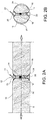
- an integrated measuring system 9 comprises a structural element 10, adapted to be incorporated into a building construction and elongated in a longitudinal direction.
- This structural element 10 is subject to an action F (in the example shown, a tensile stress applied to the ends of element 10).
- the structural element 10 has a longitudinal axis 11; in the example shown, such element 10 has a circular cross-section and is substantially axially symmetrical with respect to the axis 11.
- the structural element 10 is a metallic bar or rod, intended to be embedded in a reinforced concrete element.
- a metallic bar or rod for reinforced concrete also known as "rebar”
- rebar is a reinforcing bar intended to be used as a tension device in reinforced concrete structures to strengthen and aid the concrete under tension.
- a measuring system 12 suitable to measure deformations and/or stresses on the structural element 10 along said longitudinal direction, is at least partially housed in a cavity 14 inside such element 10.
- the cavity 14 is transversely extended with respect to the structural element 10 and perpendicularly to the longitudinal axis 11.
- the cavity 14 passes through the structural element 10, and/or intercepts the longitudinal axis 11.
- Such cavity 14 is filled with a compressible fluid (as will be better appreciated in the following description). Conveniently, the cavity 14 is sealed or sealable hermetically.
- the cavity 14, in the case of steel bars for reinforced concrete, may be obtained by perforation, punching, excavating, laser cutting, shaping and any other type of machining of the material of the element to be evaluated for deformation variations.
- the cavity 14 is appropriately formed so as to maintain as much symmetry as possible with respect to the longitudinal axis 11 of the structural element 10, or at least with respect to a plane passing through the axis of such element.
- the measuring system 12 comprises a sensor or pressure measuring device 18 for measuring the pressure of the compressible fluid 16 contained within the cavity 14. Conveniently, the pressure measuring device 18 is immersed in the fluid 16.
- the fluid 16 introduced in the cavity 14 is selected from those that prevent the formation of corrosion inside the cavity and possess large molecules so as to avoid leakage of material.
- the compressible fluid 16 may be a gas or a mixture of gas and liquid.
- the measuring system 12 comprises a temperature measuring device that may be placed inside or outside the cavity 14 so as to measure the temperature of the fluid 16 contained in the cavity 14 and/or the inner wall of the cavity 14. It may be desirable to measure the temperature of the inner wall of the cavity 14, in addition to or as an alternative to measuring the temperature of the fluid 16 as, for example, the operation of any electronic devices of the system (which may include the aforementioned measuring devices as well as other devices, for example of the type illustrated in the following description) could change the temperature of the fluid 16 inside the cavity 14, and therefore change the pressure without the structural element actually being deformed.
- a temperature measuring device that may be placed inside or outside the cavity 14 so as to measure the temperature of the fluid 16 contained in the cavity 14 and/or the inner wall of the cavity 14. It may be desirable to measure the temperature of the inner wall of the cavity 14, in addition to or as an alternative to measuring the temperature of the fluid 16 as, for example, the operation of any electronic devices of the system (which may include the aforementioned measuring devices as well as other devices, for example of the type illustrated in the
- a thermal calibration phase of the system may be provided to isolate the contribution to longitudinal deformation due to adding or reducing heat in the structural element 10.
- Such procedure comprises the step of establishing a priori a correlation between the temperature and the deformation of the structural element 10, subject to the design operating conditions.
- This result may be obtained, for example, by performing a series of tests on a specimen subject to the same conditions in which the structural element would operate, recording the effect of one or more temperature variations on the deformation of such structural element, so as to extrapolate a rule that relates deformation and temperature.
- the system may be calibrated to take into account the contribution to the deformation due to temperature variation of the fluid 16, for example excluding such contribution from the calculation of the extent of deformation when due only to mechanical factors.
- one or more closure means 20 may be associated with the cavity 14 to seal such cavity hermetically.
- the closure means 20 is appropriately connected to the structural element 10 by means of a suitable system (for example, welding) to ensure the fluid seal 16 in the cavity 14, even when the element as a whole (and consequently also the means of closure 20) undergoes deformation.
- a suitable system for example, welding
- the cavity 14 and any closure means 20 are made in such a way as to avoid excessive stress states relative to the average stress state within element 10.
- the hermetically sealed cavity 14 may conveniently accommodate a series of other devices useful for structural monitoring, which also measure, among other things, acceleration, inclination, electrical potential, and spatial position. All of these devices, due to the configuration of the integrated measuring system 9, are very well insulated from the outside and thus protected.
- the temperature measurement has without a doubt advantages in terms of protection and risk assessment in fire conditions.
- the closing means 20 are configured so as to allow the connection between the devices measuring pressure and/or temperature 18 with a power and/or data transfer system 22, adapted to power such devices 18 and/or to communicate the data collected within the cavity 14.
- the closure component 20 must conveniently provide for the passage of any electrical connections that transmit power and signals to and from the devices 18 housed inside the cavity 14.
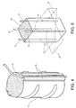
- Any power and data transmission cables or in general the data and power transfer system 22 may be housed in longitudinal ribs 26 obtained on the bars 10, suitably shaped for this purpose (as in the example shown in figure 4 ).
- Power and data transfer may also take place via a wireless system, for example using the magnetic and electrical properties of the reinforcement bars.
- the system as described above relates the deformation of a limited section of the structural element 10 (comprising the cavity 14) with the deformation before and after the cavity along the longitudinal axis 11 of the structural element.
- the additional rib 24 may be associated with the structural element 10, and has a cross section with an area corresponding to the area of the cross section of the cavity 14.
- the protrusion 24 is positioned in a radially outer position with respect to the structural element, conveniently near the portion of such element 10 wherein the cavity 14 is present.
- the protrusion 24 is positioned at the cross section of the structural element 10 on which the cavity 14 lies.
- the average deformation in the section related to the volume variation of the cavity 14 is more similar to that of the other sections of the structural element 10.
- a reduction in the overall dimensions of the system reduces the size of the outer rib 24 and the perturbations mentioned above.
- outer ribs does not significantly alter the force/deformation state of the element.
- outer rib elements are normally made during the rolling stages, to improve the adhesion between steel and concrete. The mechanical characteristics do not undergo alterations or modifications that compromise the correct structural behavior.
- the system may be realized on elements of any material for which volume changes may be obtained following the application of an action involving deformations, and wherein a hermetically sealed cavity may appropriately be formed.
- the reinforcements provided with the system described in the present patent may be conveniently arranged at the edges of the sections of such elements so as to record deformations close to the maximum points for each item and in each section.
- the areas wherein the cavities 14 of the bars 10 which comprise the reinforcement of the concrete element would be aligned on a plane orthogonal to the axis of said element 28 (pillar, beam, etc.).
- the integrated system 9 is particularly advantageous for monitoring deformations/stresses along the longitudinal axis of steel reinforcements for reinforced concrete structures.
- steel reinforcement elements may be considered as stressed predominantly along their longitudinal axis 11.
- the system may be used to make load cells.
- the measuring system 12 is integral with the structural element 10 and records the residual deformation thereof. This feature makes the system particularly useful in civil structures and infrastructures to evaluate the structural and residual safety status after an exceptional load event or seismic event occurs.
- multiple integrated measuring systems 9 may be placed in the same structural element 10, distributed in a more or less regular way along the longitudinal direction of the structural element 10.
Landscapes
- Physics & Mathematics (AREA)
- General Physics & Mathematics (AREA)
- Chemical & Material Sciences (AREA)
- Analytical Chemistry (AREA)
- Testing Of Devices, Machine Parts, Or Other Structures Thereof (AREA)
- Measuring Fluid Pressure (AREA)
- Length Measuring Devices By Optical Means (AREA)
- Force Measurement Appropriate To Specific Purposes (AREA)
Claims (13)
- Integriertes Messsystem (9), welches aufweist:- ein Strukturelement (10), das eingerichtet ist, in eine Baukonstruktion eingebaut zu werden und in eine Längsrichtung langgestreckt ist, wobei das Strukturelement (10) einen inneren Hohlraum (14) aufweist, der mittels Verschlussmitteln (20) hermetisch verschlossen oder verschließbar ist, wobei der innere Hohlraum (14) mit einem komprimierbaren Fluid (16) gefüllt ist;- ein Messsystem (12), das eingerichtet ist, Verformungen und/oder Spannungen an dem Strukturelement (10) entlang der Längsrichtung zu messen, wobei das System eine Druckmessvorrichtung (18) in Kontakt mit dem Fluid in dem inneren Hohlraum (14) aufweist, wobei das Messsystem (12) ferner eine Vorrichtung zum Messen der Temperatur des Fluids (16) und/oder der Temperatur der Innenwand des Hohlraums (14) aufweist, so dass das System in der Lage ist, eine Volumenänderung des Hohlraums (14) durch Messen einer Druck- und Temperaturänderung des Fluids zu bestimmen, die sich aus einer auf das Strukturelement (10) ausgeübten Einwirkung (F) ergibt,
wobei sich der Hohlraum (14) entlang einer Richtung erstreckt, die im Wesentlichen senkrecht zu der Längsrichtung ist, und wobei das Strukturelement (10) ein Metallstab für Stahlbeton ist. - System nach Anspruch 1, wobei der Hohlraum (14) eine zentrale Längsachse (11) des Strukturelements (10) schneidet.
- System nach Anspruch 1 oder 2, wobei der Hohlraum (14) durch das Strukturelement (10) verläuft.
- System nach einem der vorhergehenden Ansprüche, wobei das komprimierbare Fluid (16) ein Gas oder ein Flüssigkeits/Gas-Gemisch ist.
- System nach einem der vorhergehenden Ansprüche, wobei die Druckmessvorrichtung (18) in das Fluid (16) eingetaucht ist.
- System nach einem der vorhergehenden Ansprüche, wobei die Verschlussmittel (20) so konfiguriert sind, dass sie die Verbindung zwischen den Vorrichtungen zum Messen von Druck und/oder Temperatur (18) mit einem Energie- und/oder Datenübertragungssystem (22) ermöglichen, das eingerichtet ist, die Vorrichtungen (18) mit Energie zu versorgen und/oder die innerhalb des Hohlraums (14) gesammelten Daten zu übertragen.
- System nach einem der vorhergehenden Ansprüche, bei welchem dem Strukturelement (10) ein radial äußerer Vorsprung (24) zugeordnet ist, der an dem Querschnitt des Strukturelements (10) angeordnet ist, an dem der Hohlraum (14) liegt, wobei der Vorsprung einen Querschnitt mit einer Fläche aufweist, die im Wesentlichen der Fläche des Querschnitts des Hohlraums (14) entspricht.
- Verfahren zum Messen von Verformungen und/oder Spannungen entlang einer Längsrichtung eines in Längsrichtung langgestreckten Strukturelements (10), wobei das Strukturelement (10) eingerichtet ist, in eine Baukonstruktion eingebaut zu werden und einer Einwirkung F ausgesetzt werden kann, wobei das Verfahren die folgenden Schritte umfasst:a) Bereitstellen mindestens eines Hohlraums (14) im Inneren des Strukturelements (10), der in einer Richtung im Wesentlichen senkrecht in Bezug auf eine zentrale Längsachse (11) des Strukturelements (10) ausgerichtet ist, wobei das Strukturelement (10) ein Metallstab für Stahlbeton ist;b) Füllen des Hohlraums (14) mit einem komprimierbaren Fluid (16) und Abdichten des Hohlraums (14) mittels Verschlussmitteln (20);c) Zuordnen eines Messsystems (12) zu dem Hohlraum (14), wobei das Messsystem (12) eine Vorrichtung zum Messen (18) des Drucks des Fluids (16) und eine Vorrichtung zum Messen der Temperatur des Fluids (16) und/oder der Temperatur der Innenwand des Hohlraums (14) umfasst;d) Messen der Druck- und Temperaturänderungen des Fluids (16), Bestimmen einer Volumenänderung des Hohlraums (14), und Herstellen einer Beziehung zwischen der Volumenänderung und einer Längsverformung des Strukturelements (10).
- Verfahren nach Anspruch 8, wobei Schritt (b) durch Füllen des Hohlraums (14) mit einem Gas oder einem Gas/Flüssigkeitsgemisch durchgeführt wird.
- Verfahren nach Anspruch 8 oder 9, wobei der Hohlraum (14) eine zentrale Längsachse (11) des Strukturelements (10) schneidet.
- Verfahren nach einem der Ansprüche 8 bis 10, umfassend den Schritt des a priori Bestimmens einer Beziehung zwischen Temperatur und Verformung eines Strukturelements (10), das Auslegungsbetriebsbedingungen unterliegt, und des Kalibrierens des Systems, das die Temperatur- und Druckschwankungen des Fluids (16) in die Längsverformung und/oder Spannung des Strukturelements (10) umwandelt, um den Beitrag einer Temperaturschwankung des Fluids aus der Berechnung auszuschließen.
- Verfahren nach einem der Ansprüche 8 bis 11, umfassend den Schritt des Anbringens eines zusätzlichen radial äußeren Vorsprungs (24) an dem Strukturelement (10), wobei der Vorsprung (24) an dem Querschnitt des Strukturelements (10), an dem der Hohlraum (14) liegt, derart platziert wird, dass der Materialbereich, der aufgrund des Vorhandenseins des Hohlraums (14) fehlt, wiederhergestellt wird.
- Strukturelement (10), das zum Einbau in Baukonstruktionen eingerichtet ist, aufweisend eine Vielzahl von integrierten Messsystemen (9) nach einem der Ansprüche 1 bis 7.
Applications Claiming Priority (2)
| Application Number | Priority Date | Filing Date | Title |
|---|---|---|---|
| IT102016000118077A IT201600118077A1 (it) | 2016-11-22 | 2016-11-22 | Sistema integrato e metodo per la misura della deformazione e/o tensione in elementi monodimensionali. |
| PCT/IB2017/057279 WO2018096443A2 (en) | 2016-11-22 | 2017-11-21 | An integrated system and method for measuring deformations and/or stresses in one-dimensional elements |
Publications (2)
| Publication Number | Publication Date |
|---|---|
| EP3545275A2 EP3545275A2 (de) | 2019-10-02 |
| EP3545275B1 true EP3545275B1 (de) | 2021-09-08 |
Family
ID=58347763
Family Applications (1)
| Application Number | Title | Priority Date | Filing Date |
|---|---|---|---|
| EP17817878.6A Active EP3545275B1 (de) | 2016-11-22 | 2017-11-21 | Integriertes system und verfahren zur messung von verformungen und/oder spannungen bei eindimensionalen elementen |
Country Status (4)
| Country | Link |
|---|---|
| US (1) | US11092499B2 (de) |
| EP (1) | EP3545275B1 (de) |
| IT (1) | IT201600118077A1 (de) |
| WO (1) | WO2018096443A2 (de) |
Families Citing this family (4)
| Publication number | Priority date | Publication date | Assignee | Title |
|---|---|---|---|---|
| JP6789853B2 (ja) * | 2017-03-08 | 2020-11-25 | 日本電産コパル電子株式会社 | 力覚センサ |
| IT201900002663A1 (it) | 2019-02-25 | 2020-08-25 | St Microelectronics Srl | Sensore di pressione includente un trasduttore microelettromeccanico e relativo metodo di rilevazione di pressione |
| US12491057B2 (en) * | 2019-10-23 | 2025-12-09 | Solventum Intellectual Properties Company | Force sensor system |
| CN112964221A (zh) * | 2021-02-08 | 2021-06-15 | 中国矿业大学(北京) | 一种地下工程结构施工钢管柱表面应变计安装定位方法 |
Family Cites Families (7)
| Publication number | Priority date | Publication date | Assignee | Title |
|---|---|---|---|---|
| US4563906A (en) * | 1983-11-23 | 1986-01-14 | Camtech, Inc. | Load measurement apparatus including miniature instrumented hydrostatic cell |
| US6898339B2 (en) * | 2002-12-16 | 2005-05-24 | Schlumberger Technology Corporation | Multiple mode pre-loadable fiber optic pressure and temperature sensor |
| US20110257907A1 (en) * | 2010-04-16 | 2011-10-20 | Medtronic, Inc. | Pressure-based temperature estimation for implantable fluid delivery devices |
| US8979825B2 (en) * | 2011-04-15 | 2015-03-17 | Medtronic, Inc. | Implantable fluid delivery device including gas chamber pressure sensor |
| FR2983955B1 (fr) * | 2011-12-09 | 2014-10-03 | Openfield | Capteur de pression pour fluide |
| DE102013012690A1 (de) * | 2013-07-31 | 2015-02-26 | Tecsis Gmbh | Hydraulisches Biegeelement |
| DE202014005194U1 (de) * | 2014-01-14 | 2014-07-23 | Technische Universität Ilmenau | Vorrichtung zur Detektion einer Kraft |
-
2016
- 2016-11-22 IT IT102016000118077A patent/IT201600118077A1/it unknown
-
2017
- 2017-11-21 US US16/462,783 patent/US11092499B2/en active Active
- 2017-11-21 WO PCT/IB2017/057279 patent/WO2018096443A2/en not_active Ceased
- 2017-11-21 EP EP17817878.6A patent/EP3545275B1/de active Active
Also Published As
| Publication number | Publication date |
|---|---|
| US11092499B2 (en) | 2021-08-17 |
| IT201600118077A1 (it) | 2018-05-22 |
| WO2018096443A3 (en) | 2018-07-05 |
| US20190316979A1 (en) | 2019-10-17 |
| EP3545275A2 (de) | 2019-10-02 |
| WO2018096443A2 (en) | 2018-05-31 |
Similar Documents
| Publication | Publication Date | Title |
|---|---|---|
| Zhang et al. | Fiber optic sensing of concrete cracking and rebar deformation using several types of cable | |
| Kulpa et al. | Strain and displacement measurement based on distributed fibre optic sensing (DFOS) system integrated with FRP composite sandwich panel | |
| Lan et al. | Monitoring of structural prestress loss in RC beams by inner distributed Brillouin and fiber Bragg grating sensors on a single optical fiber | |
| Bado et al. | Distributed Sensing (DOFS) in Reinforced Concrete members for reinforcement strain monitoring, crack detection and bond-slip calculation | |
| Klar et al. | Distributed strain measurement for pile foundations | |
| Wang et al. | Priority design parameters of industrialized optical fiber sensors in civil engineering | |
| Xu et al. | Evaluation of interface shear behavior of GFRP soil nails with a strain-transfer model and distributed fiber-optic sensors | |
| EP3545275B1 (de) | Integriertes system und verfahren zur messung von verformungen und/oder spannungen bei eindimensionalen elementen | |
| Malek et al. | Postyield bond deterioration and damage assessment of RC beams using distributed fiber-optic strain sensing system | |
| Hong et al. | Application of distributed optical fiber sensor for monitoring the mechanical performance of a driven pile | |
| JP2020091162A (ja) | Pc桁の残存プレストレス力推定方法 | |
| Quiertant et al. | Deformation monitoring of reinforcement bars with a distributed fiber optic sensor for the SHM of reinforced concrete structures | |
| Biswal et al. | Measurement of existing prestressing force in concrete structures through an embedded vibrating beam strain gauge | |
| Sonnenfeld et al. | Microstructured optical fiber Bragg grating as an internal three-dimensional strain sensor for composite laminates | |
| Hong et al. | Deformation monitoring of long GFRP bar soil nails using distributed optical fiber sensing technology | |
| Hyett et al. | Enlightening bolts: using distributed optical sensing to measure the strain profile along fully grouted rock bolts | |
| Flynn et al. | Instrumented concrete pile tests–part 1: a review of instrumentation and procedures | |
| Qin et al. | Range‐expansion technology and fatigue performance study on the self‐sensing steel strand with an embedded fibre Bragg grating sensor | |
| Matveenko et al. | On application of distributed FOS embedded into material for the mechanical state monitoring of civil structures | |
| Liu et al. | Fiber Bragg Grating-based smart cable force sensing under bending-tension coupling | |
| Li et al. | Sensitivity enhancement of long-gage FBG sensors for macro-strain measurements | |
| Lee et al. | Measurement of bar strain during pull-out tests: use of electrical resistance gauge methods under large displacement | |
| Han et al. | Steel stress redistribution and fatigue life estimation of partially prestressed concrete beams under fatigue loading | |
| Mao et al. | An optical fiber sensor method for simultaneously monitoring corrosion and structural strain induced by loading | |
| Beddelee et al. | Bored piles imperfection detection using optical fibre sensor: laboratory simulated |
Legal Events
| Date | Code | Title | Description |
|---|---|---|---|
| STAA | Information on the status of an ep patent application or granted ep patent |
Free format text: STATUS: UNKNOWN |
|
| STAA | Information on the status of an ep patent application or granted ep patent |
Free format text: STATUS: THE INTERNATIONAL PUBLICATION HAS BEEN MADE |
|
| PUAI | Public reference made under article 153(3) epc to a published international application that has entered the european phase |
Free format text: ORIGINAL CODE: 0009012 |
|
| STAA | Information on the status of an ep patent application or granted ep patent |
Free format text: STATUS: REQUEST FOR EXAMINATION WAS MADE |
|
| 17P | Request for examination filed |
Effective date: 20190618 |
|
| AK | Designated contracting states |
Kind code of ref document: A2 Designated state(s): AL AT BE BG CH CY CZ DE DK EE ES FI FR GB GR HR HU IE IS IT LI LT LU LV MC MK MT NL NO PL PT RO RS SE SI SK SM TR |
|
| AX | Request for extension of the european patent |
Extension state: BA ME |
|
| DAV | Request for validation of the european patent (deleted) | ||
| DAX | Request for extension of the european patent (deleted) | ||
| GRAP | Despatch of communication of intention to grant a patent |
Free format text: ORIGINAL CODE: EPIDOSNIGR1 |
|
| STAA | Information on the status of an ep patent application or granted ep patent |
Free format text: STATUS: GRANT OF PATENT IS INTENDED |
|
| INTG | Intention to grant announced |
Effective date: 20210401 |
|
| GRAS | Grant fee paid |
Free format text: ORIGINAL CODE: EPIDOSNIGR3 |
|
| GRAA | (expected) grant |
Free format text: ORIGINAL CODE: 0009210 |
|
| STAA | Information on the status of an ep patent application or granted ep patent |
Free format text: STATUS: THE PATENT HAS BEEN GRANTED |
|
| RIN1 | Information on inventor provided before grant (corrected) |
Inventor name: TONDOLO, FRANCESCO |
|
| AK | Designated contracting states |
Kind code of ref document: B1 Designated state(s): AL AT BE BG CH CY CZ DE DK EE ES FI FR GB GR HR HU IE IS IT LI LT LU LV MC MK MT NL NO PL PT RO RS SE SI SK SM TR |
|
| REG | Reference to a national code |
Ref country code: GB Ref legal event code: FG4D |
|
| REG | Reference to a national code |
Ref country code: CH Ref legal event code: EP Ref country code: AT Ref legal event code: REF Ref document number: 1428989 Country of ref document: AT Kind code of ref document: T Effective date: 20210915 |
|
| REG | Reference to a national code |
Ref country code: DE Ref legal event code: R096 Ref document number: 602017045779 Country of ref document: DE |
|
| REG | Reference to a national code |
Ref country code: IE Ref legal event code: FG4D |
|
| REG | Reference to a national code |
Ref country code: LT Ref legal event code: MG9D |
|
| REG | Reference to a national code |
Ref country code: NL Ref legal event code: MP Effective date: 20210908 |
|
| PG25 | Lapsed in a contracting state [announced via postgrant information from national office to epo] |
Ref country code: SE Free format text: LAPSE BECAUSE OF FAILURE TO SUBMIT A TRANSLATION OF THE DESCRIPTION OR TO PAY THE FEE WITHIN THE PRESCRIBED TIME-LIMIT Effective date: 20210908 Ref country code: RS Free format text: LAPSE BECAUSE OF FAILURE TO SUBMIT A TRANSLATION OF THE DESCRIPTION OR TO PAY THE FEE WITHIN THE PRESCRIBED TIME-LIMIT Effective date: 20210908 Ref country code: HR Free format text: LAPSE BECAUSE OF FAILURE TO SUBMIT A TRANSLATION OF THE DESCRIPTION OR TO PAY THE FEE WITHIN THE PRESCRIBED TIME-LIMIT Effective date: 20210908 Ref country code: ES Free format text: LAPSE BECAUSE OF FAILURE TO SUBMIT A TRANSLATION OF THE DESCRIPTION OR TO PAY THE FEE WITHIN THE PRESCRIBED TIME-LIMIT Effective date: 20210908 Ref country code: FI Free format text: LAPSE BECAUSE OF FAILURE TO SUBMIT A TRANSLATION OF THE DESCRIPTION OR TO PAY THE FEE WITHIN THE PRESCRIBED TIME-LIMIT Effective date: 20210908 Ref country code: BG Free format text: LAPSE BECAUSE OF FAILURE TO SUBMIT A TRANSLATION OF THE DESCRIPTION OR TO PAY THE FEE WITHIN THE PRESCRIBED TIME-LIMIT Effective date: 20211208 Ref country code: LT Free format text: LAPSE BECAUSE OF FAILURE TO SUBMIT A TRANSLATION OF THE DESCRIPTION OR TO PAY THE FEE WITHIN THE PRESCRIBED TIME-LIMIT Effective date: 20210908 Ref country code: NO Free format text: LAPSE BECAUSE OF FAILURE TO SUBMIT A TRANSLATION OF THE DESCRIPTION OR TO PAY THE FEE WITHIN THE PRESCRIBED TIME-LIMIT Effective date: 20211208 |
|
| REG | Reference to a national code |
Ref country code: AT Ref legal event code: MK05 Ref document number: 1428989 Country of ref document: AT Kind code of ref document: T Effective date: 20210908 |
|
| PG25 | Lapsed in a contracting state [announced via postgrant information from national office to epo] |
Ref country code: LV Free format text: LAPSE BECAUSE OF FAILURE TO SUBMIT A TRANSLATION OF THE DESCRIPTION OR TO PAY THE FEE WITHIN THE PRESCRIBED TIME-LIMIT Effective date: 20210908 Ref country code: GR Free format text: LAPSE BECAUSE OF FAILURE TO SUBMIT A TRANSLATION OF THE DESCRIPTION OR TO PAY THE FEE WITHIN THE PRESCRIBED TIME-LIMIT Effective date: 20211209 |
|
| PG25 | Lapsed in a contracting state [announced via postgrant information from national office to epo] |
Ref country code: AT Free format text: LAPSE BECAUSE OF FAILURE TO SUBMIT A TRANSLATION OF THE DESCRIPTION OR TO PAY THE FEE WITHIN THE PRESCRIBED TIME-LIMIT Effective date: 20210908 |
|
| PG25 | Lapsed in a contracting state [announced via postgrant information from national office to epo] |
Ref country code: IS Free format text: LAPSE BECAUSE OF FAILURE TO SUBMIT A TRANSLATION OF THE DESCRIPTION OR TO PAY THE FEE WITHIN THE PRESCRIBED TIME-LIMIT Effective date: 20220108 Ref country code: SM Free format text: LAPSE BECAUSE OF FAILURE TO SUBMIT A TRANSLATION OF THE DESCRIPTION OR TO PAY THE FEE WITHIN THE PRESCRIBED TIME-LIMIT Effective date: 20210908 Ref country code: SK Free format text: LAPSE BECAUSE OF FAILURE TO SUBMIT A TRANSLATION OF THE DESCRIPTION OR TO PAY THE FEE WITHIN THE PRESCRIBED TIME-LIMIT Effective date: 20210908 Ref country code: RO Free format text: LAPSE BECAUSE OF FAILURE TO SUBMIT A TRANSLATION OF THE DESCRIPTION OR TO PAY THE FEE WITHIN THE PRESCRIBED TIME-LIMIT Effective date: 20210908 Ref country code: PT Free format text: LAPSE BECAUSE OF FAILURE TO SUBMIT A TRANSLATION OF THE DESCRIPTION OR TO PAY THE FEE WITHIN THE PRESCRIBED TIME-LIMIT Effective date: 20220110 Ref country code: PL Free format text: LAPSE BECAUSE OF FAILURE TO SUBMIT A TRANSLATION OF THE DESCRIPTION OR TO PAY THE FEE WITHIN THE PRESCRIBED TIME-LIMIT Effective date: 20210908 Ref country code: NL Free format text: LAPSE BECAUSE OF FAILURE TO SUBMIT A TRANSLATION OF THE DESCRIPTION OR TO PAY THE FEE WITHIN THE PRESCRIBED TIME-LIMIT Effective date: 20210908 Ref country code: EE Free format text: LAPSE BECAUSE OF FAILURE TO SUBMIT A TRANSLATION OF THE DESCRIPTION OR TO PAY THE FEE WITHIN THE PRESCRIBED TIME-LIMIT Effective date: 20210908 Ref country code: CZ Free format text: LAPSE BECAUSE OF FAILURE TO SUBMIT A TRANSLATION OF THE DESCRIPTION OR TO PAY THE FEE WITHIN THE PRESCRIBED TIME-LIMIT Effective date: 20210908 Ref country code: AL Free format text: LAPSE BECAUSE OF FAILURE TO SUBMIT A TRANSLATION OF THE DESCRIPTION OR TO PAY THE FEE WITHIN THE PRESCRIBED TIME-LIMIT Effective date: 20210908 |
|
| REG | Reference to a national code |
Ref country code: DE Ref legal event code: R097 Ref document number: 602017045779 Country of ref document: DE |
|
| PG25 | Lapsed in a contracting state [announced via postgrant information from national office to epo] |
Ref country code: MC Free format text: LAPSE BECAUSE OF FAILURE TO SUBMIT A TRANSLATION OF THE DESCRIPTION OR TO PAY THE FEE WITHIN THE PRESCRIBED TIME-LIMIT Effective date: 20210908 |
|
| PLBE | No opposition filed within time limit |
Free format text: ORIGINAL CODE: 0009261 |
|
| STAA | Information on the status of an ep patent application or granted ep patent |
Free format text: STATUS: NO OPPOSITION FILED WITHIN TIME LIMIT |
|
| PG25 | Lapsed in a contracting state [announced via postgrant information from national office to epo] |
Ref country code: LU Free format text: LAPSE BECAUSE OF NON-PAYMENT OF DUE FEES Effective date: 20211121 Ref country code: DK Free format text: LAPSE BECAUSE OF FAILURE TO SUBMIT A TRANSLATION OF THE DESCRIPTION OR TO PAY THE FEE WITHIN THE PRESCRIBED TIME-LIMIT Effective date: 20210908 Ref country code: BE Free format text: LAPSE BECAUSE OF NON-PAYMENT OF DUE FEES Effective date: 20211130 |
|
| REG | Reference to a national code |
Ref country code: BE Ref legal event code: MM Effective date: 20211130 |
|
| 26N | No opposition filed |
Effective date: 20220609 |
|
| PG25 | Lapsed in a contracting state [announced via postgrant information from national office to epo] |
Ref country code: SI Free format text: LAPSE BECAUSE OF FAILURE TO SUBMIT A TRANSLATION OF THE DESCRIPTION OR TO PAY THE FEE WITHIN THE PRESCRIBED TIME-LIMIT Effective date: 20210908 |
|
| PG25 | Lapsed in a contracting state [announced via postgrant information from national office to epo] |
Ref country code: IE Free format text: LAPSE BECAUSE OF NON-PAYMENT OF DUE FEES Effective date: 20211121 |
|
| PG25 | Lapsed in a contracting state [announced via postgrant information from national office to epo] |
Ref country code: IT Free format text: LAPSE BECAUSE OF FAILURE TO SUBMIT A TRANSLATION OF THE DESCRIPTION OR TO PAY THE FEE WITHIN THE PRESCRIBED TIME-LIMIT Effective date: 20210908 |
|
| PG25 | Lapsed in a contracting state [announced via postgrant information from national office to epo] |
Ref country code: CY Free format text: LAPSE BECAUSE OF FAILURE TO SUBMIT A TRANSLATION OF THE DESCRIPTION OR TO PAY THE FEE WITHIN THE PRESCRIBED TIME-LIMIT Effective date: 20210908 |
|
| P01 | Opt-out of the competence of the unified patent court (upc) registered |
Effective date: 20230530 |
|
| PG25 | Lapsed in a contracting state [announced via postgrant information from national office to epo] |
Ref country code: HU Free format text: LAPSE BECAUSE OF FAILURE TO SUBMIT A TRANSLATION OF THE DESCRIPTION OR TO PAY THE FEE WITHIN THE PRESCRIBED TIME-LIMIT; INVALID AB INITIO Effective date: 20171121 |
|
| PG25 | Lapsed in a contracting state [announced via postgrant information from national office to epo] |
Ref country code: MK Free format text: LAPSE BECAUSE OF FAILURE TO SUBMIT A TRANSLATION OF THE DESCRIPTION OR TO PAY THE FEE WITHIN THE PRESCRIBED TIME-LIMIT Effective date: 20210908 |
|
| PG25 | Lapsed in a contracting state [announced via postgrant information from national office to epo] |
Ref country code: MT Free format text: LAPSE BECAUSE OF FAILURE TO SUBMIT A TRANSLATION OF THE DESCRIPTION OR TO PAY THE FEE WITHIN THE PRESCRIBED TIME-LIMIT Effective date: 20210908 |
|
| PG25 | Lapsed in a contracting state [announced via postgrant information from national office to epo] |
Ref country code: TR Free format text: LAPSE BECAUSE OF FAILURE TO SUBMIT A TRANSLATION OF THE DESCRIPTION OR TO PAY THE FEE WITHIN THE PRESCRIBED TIME-LIMIT Effective date: 20210908 |
|
| REG | Reference to a national code |
Ref country code: CH Ref legal event code: U11 Free format text: ST27 STATUS EVENT CODE: U-0-0-U10-U11 (AS PROVIDED BY THE NATIONAL OFFICE) Effective date: 20251222 |
|
| PGFP | Annual fee paid to national office [announced via postgrant information from national office to epo] |
Ref country code: DE Payment date: 20251128 Year of fee payment: 9 |
|
| PGFP | Annual fee paid to national office [announced via postgrant information from national office to epo] |
Ref country code: GB Payment date: 20251125 Year of fee payment: 9 |
|
| PGFP | Annual fee paid to national office [announced via postgrant information from national office to epo] |
Ref country code: FR Payment date: 20251128 Year of fee payment: 9 |
|
| PGFP | Annual fee paid to national office [announced via postgrant information from national office to epo] |
Ref country code: CH Payment date: 20251222 Year of fee payment: 9 |