EP3545209B1 - Vibration isolator - Google Patents
Vibration isolator Download PDFInfo
- Publication number
- EP3545209B1 EP3545209B1 EP17817411.6A EP17817411A EP3545209B1 EP 3545209 B1 EP3545209 B1 EP 3545209B1 EP 17817411 A EP17817411 A EP 17817411A EP 3545209 B1 EP3545209 B1 EP 3545209B1
- Authority
- EP
- European Patent Office
- Prior art keywords
- bushing
- vibration isolator
- sleeve
- housing
- resilient core
- Prior art date
- Legal status (The legal status is an assumption and is not a legal conclusion. Google has not performed a legal analysis and makes no representation as to the accuracy of the status listed.)
- Active
Links
- 230000014759 maintenance of location Effects 0.000 claims description 36
- 238000000034 method Methods 0.000 claims description 9
- 238000004519 manufacturing process Methods 0.000 claims description 3
- 230000007704 transition Effects 0.000 description 8
- 238000009434 installation Methods 0.000 description 7
- 230000000717 retained effect Effects 0.000 description 5
- 238000002955 isolation Methods 0.000 description 4
- 238000013016 damping Methods 0.000 description 3
- 239000000463 material Substances 0.000 description 3
- 229910052751 metal Inorganic materials 0.000 description 3
- 239000002184 metal Substances 0.000 description 3
- 230000002829 reductive effect Effects 0.000 description 3
- 229910052782 aluminium Inorganic materials 0.000 description 2
- XAGFODPZIPBFFR-UHFFFAOYSA-N aluminium Chemical compound [Al] XAGFODPZIPBFFR-UHFFFAOYSA-N 0.000 description 2
- 230000000712 assembly Effects 0.000 description 2
- 238000000429 assembly Methods 0.000 description 2
- 230000006835 compression Effects 0.000 description 2
- 238000007906 compression Methods 0.000 description 2
- 238000013461 design Methods 0.000 description 2
- 230000000670 limiting effect Effects 0.000 description 2
- 238000012986 modification Methods 0.000 description 2
- 230000004048 modification Effects 0.000 description 2
- 230000000284 resting effect Effects 0.000 description 2
- 244000043261 Hevea brasiliensis Species 0.000 description 1
- 239000005062 Polybutadiene Substances 0.000 description 1
- 230000006978 adaptation Effects 0.000 description 1
- 239000000853 adhesive Substances 0.000 description 1
- 230000001070 adhesive effect Effects 0.000 description 1
- 230000004323 axial length Effects 0.000 description 1
- 239000003086 colorant Substances 0.000 description 1
- 230000008878 coupling Effects 0.000 description 1
- 238000010168 coupling process Methods 0.000 description 1
- 238000005859 coupling reaction Methods 0.000 description 1
- 230000003247 decreasing effect Effects 0.000 description 1
- 239000013536 elastomeric material Substances 0.000 description 1
- 230000001747 exhibiting effect Effects 0.000 description 1
- 238000012423 maintenance Methods 0.000 description 1
- 230000007246 mechanism Effects 0.000 description 1
- 239000000203 mixture Substances 0.000 description 1
- 229920003052 natural elastomer Polymers 0.000 description 1
- 229920001194 natural rubber Polymers 0.000 description 1
- 229920002857 polybutadiene Polymers 0.000 description 1
- 229920001296 polysiloxane Polymers 0.000 description 1
- 230000036316 preload Effects 0.000 description 1
- 230000008569 process Effects 0.000 description 1
- 230000008439 repair process Effects 0.000 description 1
- 238000012360 testing method Methods 0.000 description 1
Images


Classifications
-
- F—MECHANICAL ENGINEERING; LIGHTING; HEATING; WEAPONS; BLASTING
- F16—ENGINEERING ELEMENTS AND UNITS; GENERAL MEASURES FOR PRODUCING AND MAINTAINING EFFECTIVE FUNCTIONING OF MACHINES OR INSTALLATIONS; THERMAL INSULATION IN GENERAL
- F16F—SPRINGS; SHOCK-ABSORBERS; MEANS FOR DAMPING VIBRATION
- F16F1/00—Springs
- F16F1/36—Springs made of rubber or other material having high internal friction, e.g. thermoplastic elastomers
- F16F1/38—Springs made of rubber or other material having high internal friction, e.g. thermoplastic elastomers with a sleeve of elastic material between a rigid outer sleeve and a rigid inner sleeve or pin, i.e. bushing-type
- F16F1/3863—Springs made of rubber or other material having high internal friction, e.g. thermoplastic elastomers with a sleeve of elastic material between a rigid outer sleeve and a rigid inner sleeve or pin, i.e. bushing-type characterised by the rigid sleeves or pin, e.g. of non-circular cross-section
-
- F—MECHANICAL ENGINEERING; LIGHTING; HEATING; WEAPONS; BLASTING
- F16—ENGINEERING ELEMENTS AND UNITS; GENERAL MEASURES FOR PRODUCING AND MAINTAINING EFFECTIVE FUNCTIONING OF MACHINES OR INSTALLATIONS; THERMAL INSULATION IN GENERAL
- F16F—SPRINGS; SHOCK-ABSORBERS; MEANS FOR DAMPING VIBRATION
- F16F1/00—Springs
- F16F1/36—Springs made of rubber or other material having high internal friction, e.g. thermoplastic elastomers
- F16F1/38—Springs made of rubber or other material having high internal friction, e.g. thermoplastic elastomers with a sleeve of elastic material between a rigid outer sleeve and a rigid inner sleeve or pin, i.e. bushing-type
- F16F1/3842—Method of assembly, production or treatment; Mounting thereof
-
- F—MECHANICAL ENGINEERING; LIGHTING; HEATING; WEAPONS; BLASTING
- F16—ENGINEERING ELEMENTS AND UNITS; GENERAL MEASURES FOR PRODUCING AND MAINTAINING EFFECTIVE FUNCTIONING OF MACHINES OR INSTALLATIONS; THERMAL INSULATION IN GENERAL
- F16F—SPRINGS; SHOCK-ABSORBERS; MEANS FOR DAMPING VIBRATION
- F16F2226/00—Manufacturing; Treatments
- F16F2226/04—Assembly or fixing methods; methods to form or fashion parts
-
- F—MECHANICAL ENGINEERING; LIGHTING; HEATING; WEAPONS; BLASTING
- F16—ENGINEERING ELEMENTS AND UNITS; GENERAL MEASURES FOR PRODUCING AND MAINTAINING EFFECTIVE FUNCTIONING OF MACHINES OR INSTALLATIONS; THERMAL INSULATION IN GENERAL
- F16F—SPRINGS; SHOCK-ABSORBERS; MEANS FOR DAMPING VIBRATION
- F16F2236/00—Mode of stressing of basic spring or damper elements or devices incorporating such elements
- F16F2236/12—Mode of stressing of basic spring or damper elements or devices incorporating such elements loaded in combined stresses
- F16F2236/123—Mode of stressing of basic spring or damper elements or devices incorporating such elements loaded in combined stresses loaded in compression and shear
Definitions
- This application generally relates to the field of vibratory isolation and damping assemblies and more specifically to a vibration isolator that isolates a cabinet or other fixture or structure from vibrational loads.
- Vibration isolators and damping assemblies are commonly used in a number of disparate fields in order to isolate various structures from vibration loads.
- high-end business aircraft typically have seats, tables, credenzas, stereo and TV cabinets, glassware, etc., collectively known as "monuments", installed therein.
- These monuments are coupled, such as through a fixed bolted connection, to a seat track or other structural rail formed in the floor of the aircraft.
- a plurality of vibration isolators are positioned between the monuments and the structural rail to which the monuments are coupled for isolation purposes.
- Known vibration isolators used for the above stated purposes may include a damping feature, such as an elastomeric grommet, within the body of the vibration isolator.
- a damping feature such as an elastomeric grommet
- such grommets are typically disposed somewhat loosely within the body of the vibration isolator. As a result, these components are subject to being accidentally lost during installation of the vibration isolator.
- these grommets themselves independently vibrate, thereby increasing the natural frequency of the vibration isolator.
- these elastomeric grommets typically have a short lifespan, as compared to the remainder of the isolator assembly, due to friction between the components under loads experienced during operation, requiring excessive and undesired maintenance as well as related costs.
- the document US 5 286 014 A discloses a vibration isolator comprising a housing, a sleeve, a resilient core and two bushings.
- the housing and the resilient core of the document US 5 286 014 A are straight cylindrical shaped body having upper and/or lower flange portions.
- the vibration isolator has good high frequency performance.
- the natural frequency of the vibration isolator is effectively decreased, as compared to known vibration isolators, such as those described above.
- the resilient core has an extended life and is less prone to replacement and repair.
- vibration isolator is described.
- the vibration isolator is defined by the appended claim 1.
- the bottom portion of the housing includes an inwardly extending extension, which may be defined by an upper tapered wall and a lower tapered wall and the open-ended sleeve is defined by an upper cylindrical portion, a lower flanged portion, and a transitional portion between the upper cylindrical portion and the lower flanged portion.
- the transitional portion may be angled to mirror the lower tapered wall of the housing.
- the resilient core is coupled to the inwardly extending extension of the housing and to the upper cylindrical portion, lower flanged portion, and transitional portion of the open-ended sleeve.
- the upper surface of the resilient core may correspond to a shape of an outer surface of the first bushing.
- the upper surface of the resilient core may correspond to a shape of an outer surface of the first bushing.
- the bottom surface of the housing includes an inwardly extending extension extending substantially perpendicularly to an outer surface of the housing and wherein the open-ended sleeve is defined by a lower flanged portion extending substantially perpendicularly to an upper cylindrical portion.
- the resilient core is coupled to the inwardly extending extension of the housing and to the upper cylindrical portion and lower flanged portion of the open-ended sleeve.
- the resilient core conforms to a portion of an inner surface of the housing to form an upper surface.
- the second bushing and the first bushing each include eccentrically disposed through openings.
- the through opening of the first bushing has a shape corresponding to an exterior shape of the second bushing.
- an inner surface of the through opening of the first bushing includes a first circumferential groove, the first circumferential groove being configured to align with a second circumferential groove of the second bushing.
- the first groove and the second groove combine to form a first retention track formed between the first and second bushings.
- a first retention member can be positioned within the first retention track. The first retention member is configured to retain the second bushing relative to the first bushing.
- the open-ended sleeve further includes a third circumferential groove extending around an inner surface of the sleeve that is configured to align with a fourth circumferential groove encircling an outer surface of the first bushing to form a second retention track.
- a second retention member can be positioned within the second retention track to retain the first bushing relative to the open-ended sleeve.
- the through aperture of the second bushing can be configured to receive a fastener.
- a mounting sleeve has an interior configured to receive the vibration isolator.
- the interior of the mounting sleeve includes an inner threaded surface and the housing of the vibration isolator includes an outer threaded surface configured for engagement.
- the mounting sleeve can include a flange having a slot extending through a portion of the flange perpendicular to a longitudinal axis of the mounting sleeve.
- the flange has a mounting hole parallel to the longitudinal axis and seized to receive a fastener to engage the slot in order to selectively adjust the height of the vibration isolator within the mounting sleeve.
- the vibration isolator can have a natural frequency between 30 to 55 Hz.
- a vibration isolating monument mount includes a housing having a top surface and an opposing bottom surface.
- the mount additionally includes an open-ended sleeve having a hollow interior and an extending flange.
- the flange has a top surface and a bottom surface, the bottom surface of the flange flush with a bottom surface of the sleeve.
- a resilient core is positioned between and secured to the bottom surface of the housing and the top surface of the flange of the open-ended sleeve.
- the resilient core additionally conforms to a portion of an inner surface of the housing to form an upper surface.
- a first bushing is retained within the cylindrical sleeve such that the first bushing overlays a top surface of the resilient core.
- a second bushing is retained within the first bushing.
- a method of manufacturing a vibration isolator includes providing a housing having a top surface and an opposing bottom surface.
- the method further includes providing an open-ended sleeve having a hollow interior and an extending flange, the flange having a top surface and a bottom surface, at least a portion of the sleeve being disposed within the housing.
- the method additionally includes providing a resilient core configured to be bonded to the bottom surface of the housing and the top surface of the flange of the sleeve.
- a first bushing configured to be disposed within the sleeve such that a the first bushing overlays a top surface of the resilient core is provided and a second bushing configured to be disposed within the first bushing is provided.
- the vibration isolator 2 includes a housing 4 defined by a hollow interior and a pair of opposing open ends.
- the housing 4 is sized and configured to retain or receive a plurality of components including a resilient core 14, as well as a sleeve member 18 and a pair of bushing members; namely, a first bushing 30 and a second bushing 44.
- the housing 4 is defined by a substantially cylindrical configuration including the pair of open ends and the hollow interior.
- the open ends of the housing 4 are bounded by respective top and bottom surfaces 6, 8.
- the housing 4 is further defined by having an outer surface or wall 10 and an inner surface or wall 12.
- the outer surface 10 defines an external diameter of the housing 4, which is substantially constant over an upper cylindrical portion 3 of the housing 4.
- the upper cylindrical portion 3 of the housing 4 transitions radially inwardly to a second external diameter at a bottom portion 5 of the housing 4.
- the inner surface 12 of the housing 4 defines an internal diameter of the housing 4 which is substantially constant with the exception of an inwardly radially protruding portion 15 formed at the bottom portion 5 of the housing 4.
- the inwardly radially extending protrusion 15 is defined by an upper or top tapered wall 7, and a lower or bottom tapered wall 9, the protrusion 15 defining a circumferential necked portion.
- the housing 4 can be formed of a metal or any suitable structural material.
- the resilient core 14 is a molded component made from an elastomeric material, such as but not limited to a natural rubber, silicone, polybutadiene, or blends thereof, which is securely attached to the bottom portion 5 of the housing 4.
- the resilient core 14 has an axial to radial stiffness ratio of anywhere between about 0.5 to 2.0, though this parameter can be suitably varied.
- the resilient core 14 is substantially isoelastic, allowing the core to be responsive to applied loads in each dimension.
- the resilient core 14 is designed to be fitted within the housing 4 and is defined by respective upper 140 and lower ends 141, including an opening 142 extending through the length of the core 14.
- the outer contour of the resilient core 14 is defined by an upper cylindrical portion 11 having an annular surface which transitions via an inwardly radial surface 190 to a second annular surface 13 and in which the second annular surface 13 transitions radially outward via a surface 191 to a third annular surface 19.
- the diameter of the first annular surface 11 is larger than that of the second annular surface 13 and in which the third annular surface 19 has the largest relative diameter.
- the second annular surface 13 and the inwardly and outwardly transitioning surfaces 190, 191 correspond to the inwardly extending projection 15 of the housing 4.
- the inner contour formed by the opening 142 of the resilient core 14 also varies in diameter between the upper and lower ends 140, 141 thereof. More specifically, the upper end 140 is defined by a top surface 16 in which the opening 142 is defined by a first annular surface 143 having a first inner diameter extending axially (downwardly) into the opening 142. An annular shoulder 144 projecting radially inwardly depends from the bottom of the first annular surface 143. The diameter of the opening 142 then transitions inwardly from the defined annular shoulder 144 along a conically defined section that extends radially inwardly to a second annular surface 145 that forms a necked section of the opening 142.
- the opening 142 then extends radially outward forming an upper annular shoulder 146 and a third annular surface 147, respectively, the latter having a substantially constant diameter that extends axially to an outwardly tapering conical surface 148 and a shoulder 149 formed adjacent the lower end 141 of the resilient core 14.
- the sleeve 18 is designed to be fitted within the lower end 141 of the resilient core 14 and is defined by an upper cylindrical portion 21, a lower flanged portion 22, and a transitional portion 28 between the upper and lower portions 21, 22.
- the upper cylindrical portion 21 is defined by a first outer diameter that is substantially smaller than that of the lower flanged portion 22 wherein the transitional portion 28 is defined by an outwardly tapered conical surface therebetween.
- the sleeve 18 is further defined by a pair of opposing open ends and a through aperture 20 in which the inner diameter of the aperture 20 is substantially constant over its length with the exception of an inner shoulder 42 formed at the lower end of the sleeve 18.
- the sleeve 18 can be fabricated from any suitable structural material, such as a metal, and according to this embodiment is made from aluminum.
- the first bushing 30 is defined by a body having upper and lower ends 31, 33 as well as an eccentrically disposed axial opening 40 extending therethrough.
- the eccentrically disposed axial opening 40 is parallel to, but spaced apart from, a defined center longitudinal axis A1.
- the first bushing 30 is configured to be fitted within the upper portion 3 of the housing 4 and is engaged with the resilient core 14.
- the body of the first bushing 30 is defined by an upper flange 36 and a lower engagement portion 37, each being further defined by an outer or exterior surface.
- the outer diameter of the upper flange 36 is larger than that of the lower engagement portion 37, wherein the flange 36 includes a bottom surface 34 that inwardly extends to an annular outer surface 32 that transitions via a conical surface 35 to the lower engagement portion 37, the latter being substantially cylindrical and extending axially to the lower end 33 of the bushing 30.
- the through opening 40 is defined by a first diameter at the top of the opening 40 adjacent the upper end 31 of the bushing 30, the opening 40 forming a shoulder 42 that transitions the opening 40 to a second, smaller diameter extending along the majority of the axial length of the through opening 40 to the lower end 33.
- first and second bushings 30, 44 can be fabricated from any suitable structural material, such as a metal, and according to this embodiment each of the bushings 30, 44 is made from aluminum.
- the second bushing 44 is configured to be fitted within the through opening 40 of the first bushing 30 according to this embodiment. Still referring to FIGS. 1-3 , the second bushing 44 is defined by a substantially cylindrical body having an upper flange 50 and a lower cylindrical portion or shaft 46. Similar to the first bushing 30, the second bushing 44 has an aperture 52 axially extending through the extent of the second bushing 44 and more specifically along a defined longitudinal axis A2. According to the depicted embodiment, the second bushing 44 is an eccentric bushing in which the aperture 52 is parallel to, but offset from, the longitudinal axis A2.
- Each of the first bushing 30 and the second bushing 44 can include at least one alignment recess 68 that is formed in the upper flanges 36, 50 of the first and second bushing 30, 44, respectively.
- the at least one alignment recess 68 is configured to receive a tool (not shown) for rotating the first and second bushing 30, 44, respectively, within the housing 4.
- the resilient core 14 is disposed within the lower portion 5 of the housing 4.
- the second annular surface 13 of the resilient core 14 conforms to the inwardly extending protrusion 15 and the bottom surface 8 of the housing 4, in which the upper cylindrical portion 11 of the core 14 engages the inner surface 12 of the housing 4.
- the third annular surface 19 of the core 14 extends below the bottom surface 8 of the housing 4 and in which the top surface 16 of the resilient core 14 encircles the inner surface 12 of the housing 4 to form a ledge.
- the sleeve 18 is disposed within the lower end 141 of the resilient core 14 abutting the resilient core 14 such that the resilient core 14 is sandwiched between the housing 4 and the sleeve 18.
- the shape of the inwardly extending protrusion 15 of the housing 4 can be mirrored by the shape of the outer surface 17 of the sleeve 18.
- the protrusion 15 extending from the bottom of the inner surface 12 of the housing 4 is defined by the tapered upper and lower walls 7, 9.
- the lower flanged portion 22 transitions to the outer surface 17 of the sleeve 18 in which the angle of the transition portion 28 of the sleeve 18 corresponds to the angle of the tapered lower wall 9 of the protrusion 15 to create a secure fit.
- the resilient core 14 conforms with the outer surface 17 of the sleeve 18 as well as the inwardly extending protrusion 15 and inner surface 12 of the housing 14. Accordingly and according to this embodiment, the shape of the second annular surface 13 of the resilient core 14 conforms with the shape of the inwardly extending protrusion 15 of the housing 4 and the exterior shape of the sleeve 18.
- the design of the isolator housing 4 and the sleeve 18 can easily be varied with the preceding being an example.
- the housing 4 is defined by substantially planar inner and outer walls 12, 10 extending over the length of the housing 4, with the exception of a bottom radially inwardly extending projection 15.
- the transitional portion 28 of the sleeve 18 forms a ninety (90) degree angle between the upper cylindrical portion 21 and the flanged portion 22. While particular examples of surface shapes have been described herein, it is to be understood that other suitable shapes are contemplated.
- the resilient core 14 is fixedly coupled to both the housing 4 and the sleeve 18 in any suitable manner.
- the resilient core 14 can be mold bonded to the housing 4 and sleeve 18.
- the resilient core 14 can be coupled to the housing 4 and sleeve 18 with a suitable adhesive.
- the resilient core 14 will not be subject to friction caused by vibration of the vibration isolator 2.
- the life of the resilient core 14 is extended, as compared to a typical, loose elastomeric grommet.
- vibration of the resilient core 14, and the resulting movement relative to the housing 4 and the sleeve 18, is reduced or even eliminated, thereby reducing the natural frequency of the vibration isolator 2.
- the first bushing 30 is received or disposed within the sleeve 18 with the bottom surface 38 of the outer surface 32 resting upon the inner shoulder 24 and the bottom surface 34 of the flange 36 resting upon the top surface 16 of the resilient core 14.
- the top surface 16 of the resilient core 14 conforms to the shape of the bottom surface 34 of the upper flange 36 of the first bushing 30.
- the second bushing 44 is disposed within the through opening 40 of the first bushing 30 with the shaft 46 of the second bushing 44 extending along the length of the through opening 40 of the first bushing 30. In this position, the bottom surface 48 of the flange 50 of the second bushing 44 rests upon the formed shoulder 42 of the first bushing 30.
- the shape of the through opening 40 of the first bushing 30 conforms to the exterior shape of the second bushing 44.
- the eccentric first bushing 30 and the eccentric second bushing 44 can be oriented such that the first through opening 40 and the aperture 52 overlap. The overlap of the through opening 40 and the aperture 52, allows for rotational travel of the aperture 52.
- the aperture 52 can travel +/-0.2 inches, allowing "blind" rotational alignment with a mounting surface (not shown).
- the at least one alignment recess 68 ( FIG. 6 ) of the first bushing 30 and the second bushing 44 can be used to rotationally align the first bushing 30 and the second bushing 44 within the vibration isolator 2.
- the at least one alignment recess 68 can receive a tool (not shown) for rotating the first and second bushings 30, 44, respectively.
- a first circumferential retention groove 53 is formed in the inner surface 54 of the sleeve 18 and a second circumferential retention groove 56 is formed in the outer surface 32 of the shaft of the first bushing 30.
- a first retention member 58 such as an o-ring, can be disposed within the first retention track 57 to retain the first bushing 30 within the sleeve 18.
- a third circumferential retention groove 60 is formed in the through opening 40 of the first bushing 30 below the ridge 42 and a fourth circumferential retention groove 62 is formed in outer surface of the shaft 46 of the second bushing 44.
- the third retention groove 60 of the inner surface of the through opening 40 aligns with the fourth retention groove 62 of the outer surface of the shaft 46 such that the inner surfaces of the grooves 60, 62 form a second retention track 64 in which a second retention member 66 is disposed.
- the first retention member 58 and the second retention member 66 serve to retain the first and second bushings 30, 44 in position within the vibration isolator 2. In addition, the retention members 58, 66 prevent free rotation of the first and second bushings 30, 44, thereby maintaining alignment of the first and second bushings 30, 44 within the vibration isolator 2.
- the vibration isolator 2 can be retained within a mounting sleeve 74.
- the mounting sleeve 74 includes a cylindrically shaped lower portion 76 and an upper flange or rim 78, extending along a defined center longitudinal axis A3 of the mounting sleeve 74 and more specifically through a defined axial passage 81 of the sleeve 74 between opposing open upper and lower ends that is sized to accommodate the isolator 2.
- the upper flange 78 of the mounting sleeve 74 includes a slot 84 extending partially through the flange 78 and over a portion of the circumference thereof, the slot 84 extending substantially perpendicularly to the center longitudinal axis A3 of the mounting sleeve 74.
- the flange 78 further includes a mounting hole 86 disposed above the formed slot 84 that is configured to receive a fastener 88, such as a set screw, wherein the edges of the slot 84 can be expanded or compressed away or toward each other upon securement of the fastener 88.
- an inner surface 79 of the mounting sleeve 74 can act as a mounting surface which engages an outer surface of the vibration isolator 2.
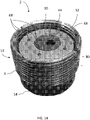
- the outer surface 10 of the housing 4 can include a set of threads ( FIG. 14 ), wherein the threads 80 are configured to threadably engage a corresponding threaded inner surface 79 of the mounting sleeve 74.
- the vibration isolator 2 can be positioned within the mounting sleeve 74 at a predetermined height, such as an installation height.
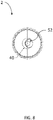
- the top surface 6 of the housing 4 can include at least one formed notch 82 ( FIGS. 11C , 12 ), in which a tool (not shown), such as a spanner wrench, can be disposed for adjusting the height of the vibration isolator 2 within the mounting sleeve 74.
- a plurality of notches 82 are formed in the top surface 6 in spaced relation. The specific number of notches 82 can be suitably varied.
- the mounting sleeve 74 can include at least one feature for locking the vibration isolator 2 at a predetermined height within the mounting sleeve 74.
- the slot 84 of the mounting sleeve 74 acts as a locking mechanism. More specifically and when the edges of the slot 84 are expanded or compressed, by securing the fastener 88 into the formed mounting hole 86 and into engagement with the upper portion of the formed slot 84, the threaded inner surface 79 becomes slightly distorted and the vibration isolator 2 is effectively locked into position within the mounting sleeve 74 that controls both height and rotation.
- the vibration isolator 2 can mount a fixture or "monument" to a surface.
- a monument 90 such as a piece of furniture in an aircraft, can be mounted to a structural rail 92 via the vibration isolator 2.
- a fastener 94 such as a bolt, extends through the vibration isolator 2 and is received in a receiving member 95, such as a nut, positioned on or beneath the structural rail 92.
- the fastener 94 extends through the bottom surface of the monument 90 and through the aperture 52 of the second bushing 30 such that the head 96 ( FIG.
- the fastener 94 rests on the second bearing 44 and the shaft 98 of the fastener 94 extends through the sleeve 18.
- the head 96 of the fastener 94 exerts a force on the second eccentric bushing 44, which in turn exerts a force on the first bushing 30, which compresses the resilient core 14.
- the resilient core 14 is subject to both compression and shear forces.
- the above-noted compression exerts a pre-load on the vibration isolator 2, reducing the natural frequency and increasing the flex life of the vibration isolator 2.
- At least one vibration isolator 2 can be used in installing or mounting a monument 90. According to at least one version, at least four (4) vibration isolators 2 can be used per monument 90. It should be noted, however, that the number of vibration isolators 2 required for an installation can be varied based on the size and/or weight of the monument 90 and other factors.
- each vibration isolator is rated to carry a given load. A variety of models can be manufactured, each model rated to carry a different load. For example, models can be manufactured to carry 25, 50, and 100 pounds, respectively.
- the housing 4 of the vibration isolator 2 can include a marking indicative of the load the vibration isolator 2 is rated to carry.
- the top 6 of the housing 4 can include a groove or notch 99 ( FIG. 11C ) that is color coded to indicate the rated load to the installer.
- a mounting tool 100 ( FIG. 16A ) can be used to position the isolator 2 and, more specifically, the aperture 52 over the fastener receiving surface 95.
- the mounting tool 100 is defined by a bold shaped member having a shaft 101 sized to fit within the aperture 52 and a flanged head 103.
- the tool 100 can include a plurality of markings 105, such as colored sections, indicating the depth of the mounting tool 100 in spaced relation along a portion of the shaft 101 in varying colors (e.g., white, red, green) to indicate a height level.
- the mounting tool 100 can be inserted in the aperture 52 (not shown). When a predetermined marking is indicated, such as only a particular color showing, the position of the vibration isolator 2 is identified as correct, the mounting tool 100 is removed, and installation of the monument proceeds.
- vibrational loads transmitted from the mounting surface to the monument can be isolated by the vibration isolator 2. Due to the bonding of the resilient core 14to the surfaces of the housing 4 and the sleeve 18, vibration of the resilient core 14 relative to the housing 4 and sleeve 18 is reduced or even eliminated. Thus, a vibration isolator with a bonded resilient core 14, as described herein, has an improved performance as compared to a typical vibration isolator.
- FIG. 17 is a graph illustrating the improved transmissibility versus forcing frequency of a bonded core isolator (curve 102) made in accordance with either of the embodiments illustrated in Figs. 3 and 4 , and as compared to a typical isolator (herein represented by curve 104), such as the MCB0006 isolator manufactured by the Lord Corporation.
- the bonded core vibration isolator operates at a lower or reduced natural frequency in the range between about 30 to 55 Hz, such as at 45 Hz and exhibits 90% isolation at a frequency of about 125Hz, as compared to the known isolator exhibiting a much higher natural frequency and as denoted by the indicated delta 107.
Description
- This application generally relates to the field of vibratory isolation and damping assemblies and more specifically to a vibration isolator that isolates a cabinet or other fixture or structure from vibrational loads.
- Vibration isolators and damping assemblies are commonly used in a number of disparate fields in order to isolate various structures from vibration loads. For example, high-end business aircraft typically have seats, tables, credenzas, stereo and TV cabinets, glassware, etc., collectively known as "monuments", installed therein. These monuments are coupled, such as through a fixed bolted connection, to a seat track or other structural rail formed in the floor of the aircraft. In use, a plurality of vibration isolators are positioned between the monuments and the structural rail to which the monuments are coupled for isolation purposes.
- Known vibration isolators used for the above stated purposes may include a damping feature, such as an elastomeric grommet, within the body of the vibration isolator. However, such grommets are typically disposed somewhat loosely within the body of the vibration isolator. As a result, these components are subject to being accidentally lost during installation of the vibration isolator. In addition and due to the loose fitting nature of the elastomeric grommets within the body of the vibration isolator, these grommets themselves independently vibrate, thereby increasing the natural frequency of the vibration isolator. Furthermore, these elastomeric grommets typically have a short lifespan, as compared to the remainder of the isolator assembly, due to friction between the components under loads experienced during operation, requiring excessive and undesired maintenance as well as related costs.
- The document
US 5 286 014 A discloses a vibration isolator comprising a housing, a sleeve, a resilient core and two bushings. The housing and the resilient core of the documentUS 5 286 014 A are straight cylindrical shaped body having upper and/or lower flange portions. - Various embodiments of a vibration isolator are described herein. Advantageously and according to at least one version, the vibration isolator has good high frequency performance. In addition and according to at least one version, due to the bonded nature of a resilient core to surfaces within the confines of the vibration isolator, the natural frequency of the vibration isolator is effectively decreased, as compared to known vibration isolators, such as those described above. In addition, the resilient core has an extended life and is less prone to replacement and repair.
- According to the invention, a vibration isolator is described. The vibration isolator is defined by the appended claim 1.
- According to the invention, the bottom portion of the housing includes an inwardly extending extension, which may be defined by an upper tapered wall and a lower tapered wall and the open-ended sleeve is defined by an upper cylindrical portion, a lower flanged portion, and a transitional portion between the upper cylindrical portion and the lower flanged portion. The transitional portion may be angled to mirror the lower tapered wall of the housing. The resilient core is coupled to the inwardly extending extension of the housing and to the upper cylindrical portion, lower flanged portion, and transitional portion of the open-ended sleeve. The upper surface of the resilient core may correspond to a shape of an outer surface of the first bushing. The upper surface of the resilient core may correspond to a shape of an outer surface of the first bushing. In another embodiment, the bottom surface of the housing includes an inwardly extending extension extending substantially perpendicularly to an outer surface of the housing and wherein the open-ended sleeve is defined by a lower flanged portion extending substantially perpendicularly to an upper cylindrical portion. The resilient core is coupled to the inwardly extending extension of the housing and to the upper cylindrical portion and lower flanged portion of the open-ended sleeve. The resilient core conforms to a portion of an inner surface of the housing to form an upper surface.
- In an embodiment, the second bushing and the first bushing each include eccentrically disposed through openings. The through opening of the first bushing has a shape corresponding to an exterior shape of the second bushing. In an embodiment, an inner surface of the through opening of the first bushing includes a first circumferential groove, the first circumferential groove being configured to align with a second circumferential groove of the second bushing. The first groove and the second groove combine to form a first retention track formed between the first and second bushings. A first retention member can be positioned within the first retention track. The first retention member is configured to retain the second bushing relative to the first bushing. In an embodiment, the open-ended sleeve further includes a third circumferential groove extending around an inner surface of the sleeve that is configured to align with a fourth circumferential groove encircling an outer surface of the first bushing to form a second retention track. A second retention member can be positioned within the second retention track to retain the first bushing relative to the open-ended sleeve. The through aperture of the second bushing can be configured to receive a fastener.
- In an embodiment, a mounting sleeve has an interior configured to receive the vibration isolator. The interior of the mounting sleeve includes an inner threaded surface and the housing of the vibration isolator includes an outer threaded surface configured for engagement. The mounting sleeve can include a flange having a slot extending through a portion of the flange perpendicular to a longitudinal axis of the mounting sleeve. The flange has a mounting hole parallel to the longitudinal axis and seized to receive a fastener to engage the slot in order to selectively adjust the height of the vibration isolator within the mounting sleeve. The vibration isolator can have a natural frequency between 30 to 55 Hz.
- According to another aspect, a vibration isolating monument mount is described. The mount includes a housing having a top surface and an opposing bottom surface. The mount additionally includes an open-ended sleeve having a hollow interior and an extending flange. The flange has a top surface and a bottom surface, the bottom surface of the flange flush with a bottom surface of the sleeve. A resilient core is positioned between and secured to the bottom surface of the housing and the top surface of the flange of the open-ended sleeve. The resilient core additionally conforms to a portion of an inner surface of the housing to form an upper surface. A first bushing is retained within the cylindrical sleeve such that the first bushing overlays a top surface of the resilient core. A second bushing is retained within the first bushing.
- According to yet another aspect, a method of manufacturing a vibration isolator is described. The method includes providing a housing having a top surface and an opposing bottom surface. The method further includes providing an open-ended sleeve having a hollow interior and an extending flange, the flange having a top surface and a bottom surface, at least a portion of the sleeve being disposed within the housing. The method additionally includes providing a resilient core configured to be bonded to the bottom surface of the housing and the top surface of the flange of the sleeve. A first bushing configured to be disposed within the sleeve such that a the first bushing overlays a top surface of the resilient core is provided and a second bushing configured to be disposed within the first bushing is provided.
- These and other features and advantages will become readily apparent to those skilled in the art with reference to the following Detailed Description, in conjunction with the accompanying drawings that are first briefly described.
- The accompanying drawings, which are incorporated herein and constitute part of this specification, illustrate presently various embodiments, and, together with the general description given above and the following Detailed Description, serve to explain salient features of the invention in which:
-
FIG. 1 illustrates a top perspective view of a vibration isolator in accordance with an embodiment; -
FIG. 2A illustrates an exploded assembly view of the vibration isolator ofFIG. 1 ; -
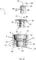
FIG. 2B illustrates the exploded assembly view of the vibration isolator ofFIGS. 1-2A , shown in section; -
FIG. 2C illustrates a partially exploded assembly view of the vibration isolator ofFIGS. 1-2B ; -
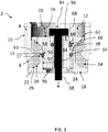
FIG. 3 illustrates a sectioned side elevational view of a vibration isolator ofFIGS. 1-2C as assembled; -
FIG. 4 illustrates a sectioned side elevational view of a vibration isolator in accordance with another embodiment; -
FIG. 5 illustrates an enlarged sectioned view of the vibration isolator ofFIGS. 1-4 ; -
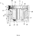
FIG. 6 illustrates a top plan view of the vibration isolator ofFIGS. 1-4 ; -
FIG. 7 illustrates a bottom perspective view of the vibration isolator ofFIGS. 1-4 ; -
FIG. 8 a bottom plan view of the vibration isolator ofFIGS. 1-4 ; -
FIG. 9 illustrates a side view of the vibration isolator ofFIGS. 1-4 ; -
FIG. 10 illustrates a top perspective view of a mounting sleeve in accordance with an embodiment; -
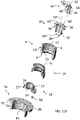
FIG. 11A illustrates an exploded assembly view of a vibration isolator and mounting sleeve, in accordance with an embodiment; -
FIG. 11B illustrates the exploded assembly view of the vibration isolator and mounting sleeve ofFIG. 11A , taken in section; -
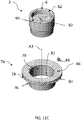
FIG. 11C illustrates a partially exploded assembly view of an assembled vibration isolator with a mounting sleeve ofFIGS. 11A-B ; -
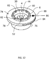
FIG. 12 illustrates a top perspective view of the assembled vibration isolator and mounting sleeve ofFIGS. 11A-C ; -
FIG. 13 illustrates a side view of the assembled vibration isolator and mounting sleeve ofFIG. 12 ; -
FIG. 14 illustrates a top perspective view of the vibration isolator ofFIG. 12 ; -
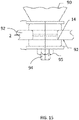
FIG. 15 illustrates a side elevational view depicting the installation of a vibration isolator in accordance with an embodiment; -
FIG. 16A illustrates a side elevational view of a mounting tool in accordance with an embodiment; -
FIG. 16B illustrates a side view depicting the engagement of the mounting tool of FIG. 17A relative to a vibration isolator; and -
FIG. 17 is a graph contrasting the performance of a known vibration isolator with a vibration isolator of the present application. - The following description should be read with reference to the accompanying drawings, in which like elements in different drawings are identically numbered for the sake of clarity. The drawings, which are not necessarily to scale, are intended to depict salient features of the design in selected embodiments and are not intended to limit intended scope. The following description illustrates by way of example, not by way of limitation, the principles of the invention. This description will clearly enable one skilled in the art to make and use the invention, and describes several embodiments, adaptations, variations, alternatives and uses of the invention, including what is presently believed to be the best mode of carrying out the invention.
- In addition, various terms are used throughout in order to provide a suitable frame of reference with regard to the accompanying drawings such as "bottom", "upper", "top", "within", "lateral", "upon", "front", "back", "inner", "outer", and the like. Unless specified, the terms described above are not intended to narrow the scope of the invention as described herein and according to the claims, except where so specifically indicated.
- Certain embodiments will now be described to provide an overall understanding of the principles of the structure, function, manufacture, and use of the systems and methods disclosed herein. One or more examples of these embodiments are illustrated in the accompanying drawings. Those skilled in the art will understand that the systems and methods specifically described herein and illustrated in the accompanying drawings are non-limiting and that the scope of the present disclosure is defined solely by the claims. For purposes of the following description, it should further be noted that the features illustrated or described in connection with one embodiment may be combined with the features of other embodiments. Such modifications and variations are intended to be included within the intended scope of the present disclosure, as defined by the appended claims. For purposes of the following embodiments, the devices and methods that are described herein are intended for use in vibration isolation of mounted objects, such as but not limited to furniture provided in high-end business aircraft.
- With reference to
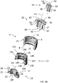
FIGS. 1 and2A , there is depicted avibration isolator 2 in accordance with a first embodiment. According to this embodiment, thevibration isolator 2 includes ahousing 4 defined by a hollow interior and a pair of opposing open ends. As discussed in greater detail, thehousing 4 is sized and configured to retain or receive a plurality of components including aresilient core 14, as well as asleeve member 18 and a pair of bushing members; namely, afirst bushing 30 and asecond bushing 44. Each of the foregoing components are now described in greater detail. - First and with reference to
FIGS. 1-3 , thehousing 4 is defined by a substantially cylindrical configuration including the pair of open ends and the hollow interior. The open ends of thehousing 4 are bounded by respective top andbottom surfaces housing 4 is further defined by having an outer surface orwall 10 and an inner surface orwall 12. According to this embodiment, theouter surface 10 defines an external diameter of thehousing 4, which is substantially constant over an uppercylindrical portion 3 of thehousing 4. As shown most clearly inFIGS. 2A and2C , the uppercylindrical portion 3 of thehousing 4 transitions radially inwardly to a second external diameter at abottom portion 5 of thehousing 4. - Still referring to
FIGS. 2A and2C , theinner surface 12 of thehousing 4 defines an internal diameter of thehousing 4 which is substantially constant with the exception of an inwardly radially protrudingportion 15 formed at thebottom portion 5 of thehousing 4. According to this embodiment, the inwardly radially extendingprotrusion 15 is defined by an upper or toptapered wall 7, and a lower or bottomtapered wall 9, theprotrusion 15 defining a circumferential necked portion. Thehousing 4 can be formed of a metal or any suitable structural material. - According to this embodiment and with reference to
FIGS. 1-3 , theresilient core 14 is a molded component made from an elastomeric material, such as but not limited to a natural rubber, silicone, polybutadiene, or blends thereof, which is securely attached to thebottom portion 5 of thehousing 4. In an embodiment, theresilient core 14 has an axial to radial stiffness ratio of anywhere between about 0.5 to 2.0, though this parameter can be suitably varied. In an embodiment, theresilient core 14 is substantially isoelastic, allowing the core to be responsive to applied loads in each dimension. - As noted, the
resilient core 14 is designed to be fitted within thehousing 4 and is defined by respective upper 140 and lower ends 141, including anopening 142 extending through the length of thecore 14. According to this embodiment, the outer contour of theresilient core 14 is defined by an uppercylindrical portion 11 having an annular surface which transitions via an inwardlyradial surface 190 to a secondannular surface 13 and in which the secondannular surface 13 transitions radially outward via asurface 191 to a thirdannular surface 19. Also and according to this embodiment, the diameter of the firstannular surface 11 is larger than that of the secondannular surface 13 and in which the thirdannular surface 19 has the largest relative diameter. As discussed herein, the secondannular surface 13 and the inwardly and outwardly transitioningsurfaces projection 15 of thehousing 4. - The inner contour formed by the
opening 142 of theresilient core 14 also varies in diameter between the upper and lower ends 140, 141 thereof. More specifically, theupper end 140 is defined by atop surface 16 in which theopening 142 is defined by a firstannular surface 143 having a first inner diameter extending axially (downwardly) into theopening 142. Anannular shoulder 144 projecting radially inwardly depends from the bottom of the firstannular surface 143. The diameter of theopening 142 then transitions inwardly from the definedannular shoulder 144 along a conically defined section that extends radially inwardly to a secondannular surface 145 that forms a necked section of theopening 142. Theopening 142 then extends radially outward forming an upperannular shoulder 146 and a thirdannular surface 147, respectively, the latter having a substantially constant diameter that extends axially to an outwardly taperingconical surface 148 and ashoulder 149 formed adjacent thelower end 141 of theresilient core 14. - The
sleeve 18 is designed to be fitted within thelower end 141 of theresilient core 14 and is defined by an uppercylindrical portion 21, a lowerflanged portion 22, and atransitional portion 28 between the upper andlower portions FIGS. 2C and3 , the uppercylindrical portion 21 is defined by a first outer diameter that is substantially smaller than that of the lowerflanged portion 22 wherein thetransitional portion 28 is defined by an outwardly tapered conical surface therebetween. Thesleeve 18 is further defined by a pair of opposing open ends and a throughaperture 20 in which the inner diameter of theaperture 20 is substantially constant over its length with the exception of aninner shoulder 42 formed at the lower end of thesleeve 18. Thesleeve 18 can be fabricated from any suitable structural material, such as a metal, and according to this embodiment is made from aluminum. - With continued reference to
FIGS. 1-3 , thefirst bushing 30 is defined by a body having upper and lower ends 31, 33 as well as an eccentrically disposedaxial opening 40 extending therethrough. The eccentrically disposedaxial opening 40 is parallel to, but spaced apart from, a defined center longitudinal axis A1. As discussed herein, thefirst bushing 30 is configured to be fitted within theupper portion 3 of thehousing 4 and is engaged with theresilient core 14. - The body of the
first bushing 30 is defined by anupper flange 36 and alower engagement portion 37, each being further defined by an outer or exterior surface. According to this embodiment, the outer diameter of theupper flange 36 is larger than that of thelower engagement portion 37, wherein theflange 36 includes abottom surface 34 that inwardly extends to an annularouter surface 32 that transitions via aconical surface 35 to thelower engagement portion 37, the latter being substantially cylindrical and extending axially to thelower end 33 of thebushing 30. According to the herein described embodiment, the throughopening 40 is defined by a first diameter at the top of theopening 40 adjacent theupper end 31 of thebushing 30, theopening 40 forming ashoulder 42 that transitions theopening 40 to a second, smaller diameter extending along the majority of the axial length of the throughopening 40 to thelower end 33. Each of the first andsecond bushings bushings - The
second bushing 44 is configured to be fitted within the through opening 40 of thefirst bushing 30 according to this embodiment. Still referring toFIGS. 1-3 , thesecond bushing 44 is defined by a substantially cylindrical body having anupper flange 50 and a lower cylindrical portion orshaft 46. Similar to thefirst bushing 30, thesecond bushing 44 has anaperture 52 axially extending through the extent of thesecond bushing 44 and more specifically along a defined longitudinal axis A2. According to the depicted embodiment, thesecond bushing 44 is an eccentric bushing in which theaperture 52 is parallel to, but offset from, the longitudinal axis A2. Each of thefirst bushing 30 and thesecond bushing 44, according to this embodiment, can include at least onealignment recess 68 that is formed in theupper flanges second bushing alignment recess 68 is configured to receive a tool (not shown) for rotating the first andsecond bushing housing 4. - Returning to
FIGS. 2A-3 and with particular reference to the assembled depiction atFIGS. 2C and3 , theresilient core 14 is disposed within thelower portion 5 of thehousing 4. In the assembled position, the secondannular surface 13 of theresilient core 14 conforms to the inwardly extendingprotrusion 15 and thebottom surface 8 of thehousing 4, in which the uppercylindrical portion 11 of thecore 14 engages theinner surface 12 of thehousing 4. In the assembled position, the thirdannular surface 19 of thecore 14 extends below thebottom surface 8 of thehousing 4 and in which thetop surface 16 of theresilient core 14 encircles theinner surface 12 of thehousing 4 to form a ledge. Thesleeve 18 is disposed within thelower end 141 of theresilient core 14 abutting theresilient core 14 such that theresilient core 14 is sandwiched between thehousing 4 and thesleeve 18. - The shape of the inwardly extending
protrusion 15 of thehousing 4 can be mirrored by the shape of theouter surface 17 of thesleeve 18. In an embodiment, illustrated byFIG. 3 , theprotrusion 15 extending from the bottom of theinner surface 12 of thehousing 4 is defined by the tapered upper andlower walls flanged portion 22 transitions to theouter surface 17 of thesleeve 18 in which the angle of thetransition portion 28 of thesleeve 18 corresponds to the angle of the taperedlower wall 9 of theprotrusion 15 to create a secure fit. Theresilient core 14 conforms with theouter surface 17 of thesleeve 18 as well as the inwardly extendingprotrusion 15 andinner surface 12 of thehousing 14. Accordingly and according to this embodiment, the shape of the secondannular surface 13 of theresilient core 14 conforms with the shape of the inwardly extendingprotrusion 15 of thehousing 4 and the exterior shape of thesleeve 18. - For purposes of the inventive concepts described herein, it should be noted that the design of the
isolator housing 4 and thesleeve 18 can easily be varied with the preceding being an example. For example, and according to another embodiment, illustrated byFIG. 4 , thehousing 4 is defined by substantially planar inner andouter walls housing 4, with the exception of a bottom radially inwardly extendingprojection 15. In this embodiment, thetransitional portion 28 of thesleeve 18 forms a ninety (90) degree angle between the uppercylindrical portion 21 and theflanged portion 22. While particular examples of surface shapes have been described herein, it is to be understood that other suitable shapes are contemplated. - The
resilient core 14 is fixedly coupled to both thehousing 4 and thesleeve 18 in any suitable manner. For example, theresilient core 14 can be mold bonded to thehousing 4 andsleeve 18. In another example, theresilient core 14 can be coupled to thehousing 4 andsleeve 18 with a suitable adhesive. By fixedly coupling to thehousing 4 andsleeve 18, theresilient core 14 will not be subject to friction caused by vibration of thevibration isolator 2. Thus, the life of theresilient core 14 is extended, as compared to a typical, loose elastomeric grommet. In addition, vibration of theresilient core 14, and the resulting movement relative to thehousing 4 and thesleeve 18, is reduced or even eliminated, thereby reducing the natural frequency of thevibration isolator 2. - Returning to
FIGS. 2A-4 , thefirst bushing 30 is received or disposed within thesleeve 18 with thebottom surface 38 of theouter surface 32 resting upon theinner shoulder 24 and thebottom surface 34 of theflange 36 resting upon thetop surface 16 of theresilient core 14. According to this embodiment, thetop surface 16 of theresilient core 14 conforms to the shape of thebottom surface 34 of theupper flange 36 of thefirst bushing 30. - As illustrated by
FIGS. 2A-4 , thesecond bushing 44 is disposed within the through opening 40 of thefirst bushing 30 with theshaft 46 of thesecond bushing 44 extending along the length of the through opening 40 of thefirst bushing 30. In this position, thebottom surface 48 of theflange 50 of thesecond bushing 44 rests upon the formedshoulder 42 of thefirst bushing 30. In an embodiment, the shape of the through opening 40 of thefirst bushing 30 conforms to the exterior shape of thesecond bushing 44. In an embodiment, illustrated byFIGS. 7-8 , the eccentricfirst bushing 30 and the eccentricsecond bushing 44 can be oriented such that the first throughopening 40 and theaperture 52 overlap. The overlap of the throughopening 40 and theaperture 52, allows for rotational travel of theaperture 52. For example, theaperture 52 can travel +/-0.2 inches, allowing "blind" rotational alignment with a mounting surface (not shown). The at least one alignment recess 68 (FIG. 6 ) of thefirst bushing 30 and thesecond bushing 44 can be used to rotationally align thefirst bushing 30 and thesecond bushing 44 within thevibration isolator 2. For example, the at least onealignment recess 68 can receive a tool (not shown) for rotating the first andsecond bushings - Therefore, the
first bushing 30 is retained within thesleeve 18 and thesecond bushing 44 is retained within thefirst bushing 30. According to this embodiment and as illustrated inFIGS. 3 and5 , a firstcircumferential retention groove 53 is formed in theinner surface 54 of thesleeve 18 and a secondcircumferential retention groove 56 is formed in theouter surface 32 of the shaft of thefirst bushing 30. When thefirst bushing 30 is received within thesleeve 18, thefirst retention groove 53 of theinner surface 54 of thesleeve 18 and thesecond retention groove 56 in theouter surface 32 of theshaft 37 align with one another such that the inner surfaces of thegrooves first retention track 57 encircling the outer circumference of thefirst bushing 30. Afirst retention member 58, such as an o-ring, can be disposed within thefirst retention track 57 to retain thefirst bushing 30 within thesleeve 18. Similarly, a thirdcircumferential retention groove 60 is formed in the through opening 40 of thefirst bushing 30 below theridge 42 and a fourthcircumferential retention groove 62 is formed in outer surface of theshaft 46 of thesecond bushing 44. When thesecond bushing 44 is disposed within thefirst bushing 30, thethird retention groove 60 of the inner surface of the throughopening 40 aligns with thefourth retention groove 62 of the outer surface of theshaft 46 such that the inner surfaces of thegrooves second retention track 64 in which asecond retention member 66 is disposed. Thefirst retention member 58 and thesecond retention member 66 serve to retain the first andsecond bushings vibration isolator 2. In addition, theretention members second bushings second bushings vibration isolator 2. - As illustrated by
FIGS. 10-13 , thevibration isolator 2 can be retained within a mountingsleeve 74. According to this embodiment, the mountingsleeve 74 includes a cylindrically shapedlower portion 76 and an upper flange orrim 78, extending along a defined center longitudinal axis A3 of the mountingsleeve 74 and more specifically through a definedaxial passage 81 of thesleeve 74 between opposing open upper and lower ends that is sized to accommodate theisolator 2. In the depicted embodiment, theupper flange 78 of the mountingsleeve 74 includes aslot 84 extending partially through theflange 78 and over a portion of the circumference thereof, theslot 84 extending substantially perpendicularly to the center longitudinal axis A3 of the mountingsleeve 74. Theflange 78 further includes a mountinghole 86 disposed above the formedslot 84 that is configured to receive afastener 88, such as a set screw, wherein the edges of theslot 84 can be expanded or compressed away or toward each other upon securement of thefastener 88. - According to this embodiment, an
inner surface 79 of the mountingsleeve 74 can act as a mounting surface which engages an outer surface of thevibration isolator 2. According to at least one version, theouter surface 10 of thehousing 4 can include a set of threads (FIG. 14 ), wherein thethreads 80 are configured to threadably engage a corresponding threadedinner surface 79 of the mountingsleeve 74. - The
vibration isolator 2 can be positioned within the mountingsleeve 74 at a predetermined height, such as an installation height. To permit this adjustment, thetop surface 6 of thehousing 4 can include at least one formed notch 82 (FIGS. 11C ,12 ), in which a tool (not shown), such as a spanner wrench, can be disposed for adjusting the height of thevibration isolator 2 within the mountingsleeve 74. According to this version, a plurality ofnotches 82 are formed in thetop surface 6 in spaced relation. The specific number ofnotches 82 can be suitably varied. - The mounting
sleeve 74 can include at least one feature for locking thevibration isolator 2 at a predetermined height within the mountingsleeve 74. In the illustrated embodiment, theslot 84 of the mountingsleeve 74 acts as a locking mechanism. More specifically and when the edges of theslot 84 are expanded or compressed, by securing thefastener 88 into the formed mountinghole 86 and into engagement with the upper portion of the formedslot 84, the threadedinner surface 79 becomes slightly distorted and thevibration isolator 2 is effectively locked into position within the mountingsleeve 74 that controls both height and rotation. - As illustrated by
FIG. 15 , thevibration isolator 2 can mount a fixture or "monument" to a surface. In the depicted version, amonument 90, such as a piece of furniture in an aircraft, can be mounted to astructural rail 92 via thevibration isolator 2. In this example, afastener 94, such as a bolt, extends through thevibration isolator 2 and is received in a receivingmember 95, such as a nut, positioned on or beneath thestructural rail 92. In an example, thefastener 94 extends through the bottom surface of themonument 90 and through theaperture 52 of thesecond bushing 30 such that the head 96 (FIG. 3 ) of thefastener 94 rests on thesecond bearing 44 and theshaft 98 of thefastener 94 extends through thesleeve 18. As thefastener 94 is installed, thehead 96 of thefastener 94 exerts a force on the secondeccentric bushing 44, which in turn exerts a force on thefirst bushing 30, which compresses theresilient core 14. Thus, theresilient core 14 is subject to both compression and shear forces. Moreover, the above-noted compression exerts a pre-load on thevibration isolator 2, reducing the natural frequency and increasing the flex life of thevibration isolator 2. - At least one
vibration isolator 2 can be used in installing or mounting amonument 90. According to at least one version, at least four (4)vibration isolators 2 can be used permonument 90. It should be noted, however, that the number ofvibration isolators 2 required for an installation can be varied based on the size and/or weight of themonument 90 and other factors. In an example, each vibration isolator is rated to carry a given load. A variety of models can be manufactured, each model rated to carry a different load. For example, models can be manufactured to carry 25, 50, and 100 pounds, respectively. In an example, thehousing 4 of thevibration isolator 2 can include a marking indicative of the load thevibration isolator 2 is rated to carry. For example, thetop 6 of thehousing 4 can include a groove or notch 99 (FIG. 11C ) that is color coded to indicate the rated load to the installer. - In some examples, installation areas are difficult to visualize. A mounting tool 100 (
FIG. 16A ) can be used to position theisolator 2 and, more specifically, theaperture 52 over thefastener receiving surface 95. In this example, the mountingtool 100 is defined by a bold shaped member having ashaft 101 sized to fit within theaperture 52 and aflanged head 103. Thetool 100 can include a plurality ofmarkings 105, such as colored sections, indicating the depth of the mountingtool 100 in spaced relation along a portion of theshaft 101 in varying colors (e.g., white, red, green) to indicate a height level. As illustrated inFIG. 16B , during installation, the mountingtool 100 can be inserted in the aperture 52 (not shown). When a predetermined marking is indicated, such as only a particular color showing, the position of thevibration isolator 2 is identified as correct, the mountingtool 100 is removed, and installation of the monument proceeds. - During operation, vibrational loads transmitted from the mounting surface to the monument can be isolated by the
vibration isolator 2. Due to the bonding of the resilient core 14to the surfaces of thehousing 4 and thesleeve 18, vibration of theresilient core 14 relative to thehousing 4 andsleeve 18 is reduced or even eliminated. Thus, a vibration isolator with a bondedresilient core 14, as described herein, has an improved performance as compared to a typical vibration isolator. - The advantages of the herein described vibration isolator are shown graphically as compared to typically known versions.
FIG. 17 is a graph illustrating the improved transmissibility versus forcing frequency of a bonded core isolator (curve 102) made in accordance with either of the embodiments illustrated inFigs. 3 and4 , and as compared to a typical isolator (herein represented by curve 104), such as the MCB0006 isolator manufactured by the Lord Corporation. As shown in the depicted test results, the bonded core vibration isolator operates at a lower or reduced natural frequency in the range between about 30 to 55 Hz, such as at 45 Hz and exhibits 90% isolation at a frequency of about 125Hz, as compared to the known isolator exhibiting a much higher natural frequency and as denoted by the indicateddelta 107. - While particular variations and illustrative figures having been used in the foregoing description, those of ordinary skill in the art will recognize that the variations and figures are not intended to be limiting. In addition, where methods and steps described above indicate certain events occurring in certain order, those of ordinary skill in the art will recognize that the ordering of certain steps may be modified and that such modifications are in accordance with those as would be apparent to a person of suitable skill in the field. Additionally, certain of the steps may be performed concurrently in a parallel process when possible, as well as performed sequentially as described above. Therefore, to the extent there are variations, which are within the scope of the disclosure which is defined solely by the appended claims, it is the intent that this patent will cover those variations as well.
Claims (15)
- A vibration isolator comprising:a housing (4) having an upper portion (3) including a top surface (6), a bottom portion (5) having an inwardly extending protrusion (15) and a bottom surface (8) and a hollow interior;a sleeve (18) having a hollow interior, an upper cylindrical portion (21) and a lower flanged portion (22) extending substantially perpendicular to the upper cylindrical portion, the lower flanged portion (22) having a top surface (26) and a bottom surface;a resilient core (14) defined by: first (11); second (13); and third (19) annular surfaces and two transitional surfaces (190, 191) in which one transitional surface (190) extends inwardly and radially from the upper cylindrical portion (21) to the second annular surface (13), and the other transitional surface (191) extends radially outward from the second annular surface (13) to the third annular surface (19), in which the second annular surface (13) and the two transitional surfaces (190, 191) correspond to the inwardly extending projection (15) of the housing (4), the resilient core (14) having a hollow interior, positioned between and fixedly coupled to the bottom portion (5) of the housing (4) and the top surface (26) of the lower flanged portion (22) of the sleeve (18), a portion of the resilient core (14) and the sleeve (18) extending outwardly from the bottom portion (5) of the housing (4) wherein the lower flanged portion (22) of the sleeve (18) extends outwardly via a transitional portion (28) which is defined by an outwardly tapered conical surface between the upper cylindrical portion (21) and the lower flanged portion (22) or a ninety degree angle between the upper cylindrical portion (21) and the lower flanged portion (22), the inwardly extending protrusion (15) of the housing (4) engaging an outer surface of the resilient core (14);a first bushing (30) disposed within the interior of the sleeve (18), the first bushing (30) having a flange (36) including a bottom surface that overlays a top surface of the resilient core (14); anda second bushing (44) disposed within the first bushing (30).
- The vibration isolator of claim 1, wherein the inwardly extending extension (15) is defined by an upper tapered wall (7) and a lower tapered wall (9) and the transitional portion (28) being angled to mirror the lower tapered wall (9) of the housing (4).
- The vibration isolator of claim 1, wherein a top surface (16) of the resilient core (14) corresponds to a shape of an outer surface (32) of the first bushing (30).
- The vibration isolator of claim 1, wherein the inwardly extending protrusion (15) extends substantially perpendicularly to an outer surface (10) of the housing (4) and wherein the sleeve (18) is defined by the lower flanged portion (22) extending substantially perpendicularly to an upper cylindrical portion (21).
- The vibration isolator of claim 1, wherein the second bushing (44) and the first bushing (30) each include eccentrically disposed through openings (52),(40).
- The vibration isolator of claim 5, wherein the through opening (4) of the first bushing (30) has a shape corresponding to an exterior shape of the second bushing (44).
- The vibration isolator of claim 1, wherein an inner surface of the through opening (40) of the first bushing (30) comprises a first retention groove (53), the first retention groove (53) being configured to align with a second retention groove (56) of the second bushing (44), wherein the first retention groove (53) and the second groove (56) combine to form a first retention track (57) formed between the first and second bushings (30),(44).
- The vibration isolator of claim 7, further comprising a first retention member (58) positioned within the first retention track (57), the first retention member (58) being configured to retain the second bushing (44) relative to the first bushing (30).
- The vibration isolator of claim 7, wherein the sleeve (18) further comprises a third retention groove (60) extending around an inner surface of the sleeve (18) that is configured to align with a fourth retention groove (62) encircling an outer surface (32) of the first bushing (30) to form a second retention track (64).
- The vibration isolator of claim 9, wherein a second retention member (66) is positioned within the second retention track (64) to retain the first bushing (30) relative to the sleeve (18).
- The vibration isolator of claim 1, wherein the through aperture (52) of the second bushing (44) is configured to receive a fastener (94).
- The vibration isolator of claim 1, further comprising a mounting sleeve (74) having an interior configured to receive the vibration isolator (2).
- The vibration isolator of claim 12, wherein the interior of the mounting sleeve (74) includes an inner threaded surface (79) and the housing (4) of the vibration isolator (2) includes an outer threaded surface (80) configured for engagement.
- The vibration isolator of claim 13, wherein the mounting sleeve (74) comprises a flange (78) having a slot (84) extending through a portion of the flange (78) perpendicular to a longitudinal axis (A3) of the mounting sleeve (74), the mounting flange (78) having a mounting hole (86) parallel to the longitudinal axis (A3) and sized to receive a fastener (88) to engage the slot (84) in order to selectively adjust the height of the vibration isolator (2) within the mounting sleeve (74).
- A method of manufacturing a vibration isolator, the method comprising:providing a housing (4) having an upper cylindrical portion (3) including a top surface (6), a hollow interior and a bottom portion (5) having an inwardly extending protrusion (15) and a bottom surface (8);providing a sleeve (18) having a hollow interior, an upper cylindrical portion (21) and a lower flanged portion (22) extending substantially perpendicular to the upper cylindrical portion, the lower flanged portion (22) having a top surface (26) and a bottom surface;providing a resilient core (14) defined by: first (11); second (13); and third (19) annular surfaces and two transitional surfaces (190, 191) in which one transitional surface (190) extends inwardly and radially from the upper cylindrical portion (21) to the second annular surface (13), and the other transitional surface (191) extends radially outward from the second annular surface (13) to the third annular surface (19), in which the second annular surface (13) and the two transitional surfaces (190, 191) correspond to the inwardly extending projection (15) of the housing (4), the resilient core being configured to be bonded to the bottom surface (8) of the housing (4) and the top surface (26) of the lower flanged portion (22) of the sleeve wherein a portion of the resilient core (14) and the sleeve (18) extend outwardly from the bottom portion (8) of the housing (4) and the inwardly extending protrusion (15) engages an outer surface of the resilient core (14) wherein the lower flanged portion (22) of the sleeve (18) extends outwardly via a transitional portion (28), which is defined by an outwardly tapered conical surface between the upper cylindrical portion (21) and the lower flanged portion (22) or a ninety degree angle between the upper cylindrical portion (21) and the lower flanged portion (22);providing a first bushing (30) configured to be disposed within the sleeve (18) such that the first bushing (30) overlays a top surface of the resilient core (14); andproviding a second bushing (44) configured to be disposed within the first bushing (30).
Applications Claiming Priority (3)
| Application Number | Priority Date | Filing Date | Title |
|---|---|---|---|
| US201662425734P | 2016-11-23 | 2016-11-23 | |
| US15/817,796 US10655697B2 (en) | 2016-11-23 | 2017-11-20 | Vibration isolator |
| PCT/US2017/062671 WO2018098102A1 (en) | 2016-11-23 | 2017-11-21 | Vibration isolator |
Publications (2)
| Publication Number | Publication Date |
|---|---|
| EP3545209A1 EP3545209A1 (en) | 2019-10-02 |
| EP3545209B1 true EP3545209B1 (en) | 2023-01-18 |
Family
ID=62144801
Family Applications (1)
| Application Number | Title | Priority Date | Filing Date |
|---|---|---|---|
| EP17817411.6A Active EP3545209B1 (en) | 2016-11-23 | 2017-11-21 | Vibration isolator |
Country Status (4)
| Country | Link |
|---|---|
| US (1) | US10655697B2 (en) |
| EP (1) | EP3545209B1 (en) |
| CN (1) | CN110678666B (en) |
| WO (1) | WO2018098102A1 (en) |
Families Citing this family (6)
| Publication number | Priority date | Publication date | Assignee | Title |
|---|---|---|---|---|
| EP3173656B1 (en) * | 2014-07-22 | 2019-09-25 | Wel Research Co., Ltd. | Shock absorbing device |
| FR3057310B1 (en) * | 2016-10-11 | 2019-07-05 | Jtekt Europe | DAMPER BEARING WITH AXIAL PRE-LOAD |
| CN108976624B (en) * | 2018-06-30 | 2021-06-15 | 宁国九鼎橡塑制品有限公司 | Preparation method of damping bushing rubber material |
| DE102021101999A1 (en) * | 2021-01-28 | 2022-07-28 | Vibracoustic Se | Elastic bearing |
| FR3122907B1 (en) * | 2021-05-17 | 2023-04-14 | Sumitomo Riko Co Ltd | elastic joint |
| US11754142B2 (en) * | 2021-05-26 | 2023-09-12 | Bae Systems Information And Electronic Systems Integration Inc. | Low displacement, fail safe, all attitude, universal isolator |
Family Cites Families (42)
| Publication number | Priority date | Publication date | Assignee | Title |
|---|---|---|---|---|
| FR827020A (en) * | 1937-06-01 | 1938-04-14 | Metalastik | Rubber sleeve arrangement allowing reception and damping of forces acting axially |
| DE923046C (en) | 1952-02-06 | 1955-02-07 | Krauss Maffei Ag | Rubber sleeve spring for joint connections with limited space mobility |
| US2950626A (en) * | 1958-11-25 | 1960-08-30 | Black & Decker Mfg Co | Combination portable electric drill and screwdriver |
| US3399851A (en) * | 1966-08-10 | 1968-09-03 | Nichols Engineering Inc | Vibration isolator unit |
| JPS50136045A (en) * | 1974-04-15 | 1975-10-28 | ||
| US4309123A (en) * | 1979-10-26 | 1982-01-05 | Rajac Corporation | Method and apparatus for fastening misaligned structural members |
| JPS6218443U (en) * | 1985-07-18 | 1987-02-03 | ||
| US4809960A (en) * | 1987-03-26 | 1989-03-07 | Nissan Motor Co., Ltd. | Bushing assembly |
| JPH073258B2 (en) * | 1987-10-19 | 1995-01-18 | 日産自動車株式会社 | Bush assembly |
| DE3833409A1 (en) * | 1988-10-01 | 1990-04-05 | Trw Ehrenreich Gmbh | ELASTIC BEARING |
| US5131638A (en) * | 1990-10-01 | 1992-07-21 | Gencorp Inc. | Dual shock mount |
| US5286014A (en) * | 1993-02-12 | 1994-02-15 | Gencorp Inc. | Slipper bushing with improved axial load capacity |
| JP3525567B2 (en) | 1995-07-17 | 2004-05-10 | 東海ゴム工業株式会社 | Cylindrical anti-vibration support |
| IT1285032B1 (en) * | 1996-03-25 | 1998-06-03 | F I B E T S P A | GUIDE MECHANICAL CONNECTION DEVICE WITH AXIAL AND RADIAL ELASTIC LOCK WITH TORSIONAL RELEASE, IN PARTICULAR FOR |
| JP3520176B2 (en) * | 1997-03-14 | 2004-04-19 | トヨタ自動車株式会社 | Anti-vibration device |
| JP2003184924A (en) * | 2001-12-17 | 2003-07-03 | Yunimatekku Kk | High compression bush |
| US7163200B2 (en) * | 2005-03-09 | 2007-01-16 | Basf Corporation | Interlocking mount assembly for a vehicle |
| US7261365B2 (en) * | 2005-03-09 | 2007-08-28 | Basf Corporation | Vehicle body mount assembly |
| US7407234B1 (en) * | 2005-09-17 | 2008-08-05 | Robert Bosch Gmbh | Manual assembly to ABS/TCS/ESP hydraulic units |
| JP4622979B2 (en) * | 2006-09-29 | 2011-02-02 | 東海ゴム工業株式会社 | Cylindrical anti-vibration device stopper and cylindrical anti-vibration assembly |
| JP4777867B2 (en) * | 2006-12-04 | 2011-09-21 | 株式会社ブリヂストン | Anti-vibration support device |
| JP2009180330A (en) * | 2008-01-31 | 2009-08-13 | Tokai Rubber Ind Ltd | Automobile cylindrical vibration absorbing device manufacturing method |
| CN102177362B (en) * | 2008-10-09 | 2013-10-02 | 株式会社普利司通 | Vibration damping device |
| US8534658B2 (en) * | 2009-04-03 | 2013-09-17 | Jergens, Inc. | Mounting system |
| JP5815364B2 (en) * | 2010-10-26 | 2015-11-17 | 住友理工株式会社 | Member mount and its assembly structure |
| GB2486418A (en) * | 2010-12-13 | 2012-06-20 | Gm Global Tech Operations Inc | Damping vibrations in valves |
| DE102011119235B4 (en) | 2011-11-23 | 2022-03-24 | Audi Ag | Damper bearing arrangement for a vibration damper of a motor vehicle |
| JP5910863B2 (en) * | 2012-02-17 | 2016-04-27 | Nok株式会社 | Sliding bush |
| DE102012006284A1 (en) | 2012-03-29 | 2013-10-02 | Carl Freudenberg Kg | Bearing and method for its production |
| DE102012213028A1 (en) | 2012-07-25 | 2014-01-30 | Zf Friedrichshafen Ag | Elastomer bearing, particularly axle carrier bearing for motor vehicle, has plastic element which is designed as plastic injection part and is injected to elastomer body under formation of common contact surface |
| JP5603390B2 (en) * | 2012-08-28 | 2014-10-08 | 東海ゴム工業株式会社 | Cylindrical vibration isolator |
| SE538133C2 (en) | 2012-09-06 | 2016-03-15 | Scania Cv Ab | Insulator for dampening vibration |
| EP2959179A1 (en) * | 2013-02-25 | 2015-12-30 | LORD Corporation | Partitioned elastomeric journal bearing assemblies, systems and methods |
| US9068620B2 (en) * | 2013-02-27 | 2015-06-30 | The Pullman Company | Body mount having suspended ring member |
| CN203528229U (en) * | 2013-10-18 | 2014-04-09 | 安徽万安汽车零部件有限公司 | Shock absorbing bushing of automobile swing arm |
| CN103818207A (en) * | 2014-02-28 | 2014-05-28 | 安徽江淮汽车股份有限公司 | Control arm bushing assembly |
| US9605728B2 (en) * | 2014-04-16 | 2017-03-28 | Zhongli North America, Inc. | Adjustable body mount |
| CN105814335B (en) * | 2014-05-15 | 2018-01-23 | 住友理工株式会社 | Isolated supporting device |
| EP3173656B1 (en) * | 2014-07-22 | 2019-09-25 | Wel Research Co., Ltd. | Shock absorbing device |
| US20160221407A1 (en) * | 2015-01-29 | 2016-08-04 | Trelleborg Automotive Usa, Inc. | Rotationally slipping rubber bushing with axial retention feature |
| US10603970B2 (en) * | 2015-12-15 | 2020-03-31 | Anand Nvh Products Inc. | Bushing for vehicle suspension system |
| CN205423652U (en) * | 2016-03-28 | 2016-08-03 | 株洲时代新材料科技股份有限公司 | Location rubber joint |
-
2017
- 2017-11-20 US US15/817,796 patent/US10655697B2/en active Active
- 2017-11-21 WO PCT/US2017/062671 patent/WO2018098102A1/en unknown
- 2017-11-21 CN CN201780081989.5A patent/CN110678666B/en active Active
- 2017-11-21 EP EP17817411.6A patent/EP3545209B1/en active Active
Also Published As
| Publication number | Publication date |
|---|---|
| US10655697B2 (en) | 2020-05-19 |
| WO2018098102A1 (en) | 2018-05-31 |
| CN110678666B (en) | 2022-11-25 |
| CN110678666A (en) | 2020-01-10 |
| US20180142752A1 (en) | 2018-05-24 |
| EP3545209A1 (en) | 2019-10-02 |
Similar Documents
| Publication | Publication Date | Title |
|---|---|---|
| EP3545209B1 (en) | Vibration isolator | |
| US9523464B2 (en) | Cylindrical vibration-damping device equipped with outer bracket and outer bracket therefor | |
| US9476479B2 (en) | Tubular vibration-damping device used for vibration-damping connecting rod, vibration-damping connecting rod using the same, and method of manufacturing vibration-damping connecting rod | |
| US9512893B2 (en) | Tubular vibration-damping device | |
| DE102018112983B4 (en) | Motor vehicle vibration absorber | |
| GB2412712A (en) | A bushing-type engine mount | |
| US9410597B2 (en) | Radial vibration dampers for rotating shafts | |
| US20090166506A1 (en) | Engine Mount With Two Piece Core | |
| CN206461470U (en) | Electric machine support | |
| KR20190085875A (en) | Light weight hole plug | |
| US11073188B2 (en) | Oscillation damper and method for manufacturing an oscillation damper | |
| US11118647B2 (en) | Vibration damper | |
| US20190277319A1 (en) | Assembly and method for attaching two components | |
| US20030085499A1 (en) | Mount with replaceable load bearing and rebound members | |
| US10267186B2 (en) | Camshaft adjuster | |
| GB2060812A (en) | Vibration isolators | |
| CN106655591A (en) | Motor holder | |
| US20230010080A1 (en) | Spring seat, method for producing a spring seat, vibration damper and level adjustment device | |
| TWI700444B (en) | Modular bell-shaped vibration-damping mount | |
| US9810252B2 (en) | Lower member fixing device and fluid control device provided with the same | |
| KR101687694B1 (en) | Double insulation hydro mount | |
| CN212950108U (en) | Engine suspension device and automobile | |
| CN219262047U (en) | Tolerance regulator and vehicle | |
| JP6768576B2 (en) | Damping structure | |
| KR20190118446A (en) | Structure of vibration reduction means and vibration reduction means |
Legal Events
| Date | Code | Title | Description |
|---|---|---|---|
| STAA | Information on the status of an ep patent application or granted ep patent |
Free format text: STATUS: UNKNOWN |
|
| STAA | Information on the status of an ep patent application or granted ep patent |
Free format text: STATUS: THE INTERNATIONAL PUBLICATION HAS BEEN MADE |
|
| PUAI | Public reference made under article 153(3) epc to a published international application that has entered the european phase |
Free format text: ORIGINAL CODE: 0009012 |
|
| STAA | Information on the status of an ep patent application or granted ep patent |
Free format text: STATUS: REQUEST FOR EXAMINATION WAS MADE |
|
| 17P | Request for examination filed |
Effective date: 20190621 |
|
| AK | Designated contracting states |
Kind code of ref document: A1 Designated state(s): AL AT BE BG CH CY CZ DE DK EE ES FI FR GB GR HR HU IE IS IT LI LT LU LV MC MK MT NL NO PL PT RO RS SE SI SK SM TR |
|
| AX | Request for extension of the european patent |
Extension state: BA ME |
|
| DAV | Request for validation of the european patent (deleted) | ||
| DAX | Request for extension of the european patent (deleted) | ||
| STAA | Information on the status of an ep patent application or granted ep patent |
Free format text: STATUS: EXAMINATION IS IN PROGRESS |
|
| STAA | Information on the status of an ep patent application or granted ep patent |
Free format text: STATUS: EXAMINATION IS IN PROGRESS |
|
| 17Q | First examination report despatched |
Effective date: 20201026 |
|
| STAA | Information on the status of an ep patent application or granted ep patent |
Free format text: STATUS: EXAMINATION IS IN PROGRESS |
|
| GRAP | Despatch of communication of intention to grant a patent |
Free format text: ORIGINAL CODE: EPIDOSNIGR1 |
|
| STAA | Information on the status of an ep patent application or granted ep patent |
Free format text: STATUS: GRANT OF PATENT IS INTENDED |
|
| INTG | Intention to grant announced |
Effective date: 20220812 |
|
| GRAS | Grant fee paid |
Free format text: ORIGINAL CODE: EPIDOSNIGR3 |
|
| GRAA | (expected) grant |
Free format text: ORIGINAL CODE: 0009210 |
|
| STAA | Information on the status of an ep patent application or granted ep patent |
Free format text: STATUS: THE PATENT HAS BEEN GRANTED |
|
| AK | Designated contracting states |
Kind code of ref document: B1 Designated state(s): AL AT BE BG CH CY CZ DE DK EE ES FI FR GB GR HR HU IE IS IT LI LT LU LV MC MK MT NL NO PL PT RO RS SE SI SK SM TR |
|
| REG | Reference to a national code |
Ref country code: GB Ref legal event code: FG4D |
|
| REG | Reference to a national code |
Ref country code: CH Ref legal event code: EP |
|
| REG | Reference to a national code |
Ref country code: DE Ref legal event code: R096 Ref document number: 602017065620 Country of ref document: DE |
|
| REG | Reference to a national code |
Ref country code: AT Ref legal event code: REF Ref document number: 1544870 Country of ref document: AT Kind code of ref document: T Effective date: 20230215 Ref country code: IE Ref legal event code: FG4D |
|
| REG | Reference to a national code |
Ref country code: LT Ref legal event code: MG9D |
|
| REG | Reference to a national code |
Ref country code: NL Ref legal event code: MP Effective date: 20230118 |
|
| REG | Reference to a national code |
Ref country code: AT Ref legal event code: MK05 Ref document number: 1544870 Country of ref document: AT Kind code of ref document: T Effective date: 20230118 |
|
| PG25 | Lapsed in a contracting state [announced via postgrant information from national office to epo] |
Ref country code: NL Free format text: LAPSE BECAUSE OF FAILURE TO SUBMIT A TRANSLATION OF THE DESCRIPTION OR TO PAY THE FEE WITHIN THE PRESCRIBED TIME-LIMIT Effective date: 20230118 |
|
| P01 | Opt-out of the competence of the unified patent court (upc) registered |
Effective date: 20230528 |
|
| PG25 | Lapsed in a contracting state [announced via postgrant information from national office to epo] |
Ref country code: RS Free format text: LAPSE BECAUSE OF FAILURE TO SUBMIT A TRANSLATION OF THE DESCRIPTION OR TO PAY THE FEE WITHIN THE PRESCRIBED TIME-LIMIT Effective date: 20230118 Ref country code: PT Free format text: LAPSE BECAUSE OF FAILURE TO SUBMIT A TRANSLATION OF THE DESCRIPTION OR TO PAY THE FEE WITHIN THE PRESCRIBED TIME-LIMIT Effective date: 20230518 Ref country code: NO Free format text: LAPSE BECAUSE OF FAILURE TO SUBMIT A TRANSLATION OF THE DESCRIPTION OR TO PAY THE FEE WITHIN THE PRESCRIBED TIME-LIMIT Effective date: 20230418 Ref country code: LV Free format text: LAPSE BECAUSE OF FAILURE TO SUBMIT A TRANSLATION OF THE DESCRIPTION OR TO PAY THE FEE WITHIN THE PRESCRIBED TIME-LIMIT Effective date: 20230118 Ref country code: LT Free format text: LAPSE BECAUSE OF FAILURE TO SUBMIT A TRANSLATION OF THE DESCRIPTION OR TO PAY THE FEE WITHIN THE PRESCRIBED TIME-LIMIT Effective date: 20230118 Ref country code: HR Free format text: LAPSE BECAUSE OF FAILURE TO SUBMIT A TRANSLATION OF THE DESCRIPTION OR TO PAY THE FEE WITHIN THE PRESCRIBED TIME-LIMIT Effective date: 20230118 Ref country code: ES Free format text: LAPSE BECAUSE OF FAILURE TO SUBMIT A TRANSLATION OF THE DESCRIPTION OR TO PAY THE FEE WITHIN THE PRESCRIBED TIME-LIMIT Effective date: 20230118 Ref country code: AT Free format text: LAPSE BECAUSE OF FAILURE TO SUBMIT A TRANSLATION OF THE DESCRIPTION OR TO PAY THE FEE WITHIN THE PRESCRIBED TIME-LIMIT Effective date: 20230118 |
|
| PG25 | Lapsed in a contracting state [announced via postgrant information from national office to epo] |
Ref country code: SE Free format text: LAPSE BECAUSE OF FAILURE TO SUBMIT A TRANSLATION OF THE DESCRIPTION OR TO PAY THE FEE WITHIN THE PRESCRIBED TIME-LIMIT Effective date: 20230118 Ref country code: PL Free format text: LAPSE BECAUSE OF FAILURE TO SUBMIT A TRANSLATION OF THE DESCRIPTION OR TO PAY THE FEE WITHIN THE PRESCRIBED TIME-LIMIT Effective date: 20230118 Ref country code: IS Free format text: LAPSE BECAUSE OF FAILURE TO SUBMIT A TRANSLATION OF THE DESCRIPTION OR TO PAY THE FEE WITHIN THE PRESCRIBED TIME-LIMIT Effective date: 20230518 Ref country code: GR Free format text: LAPSE BECAUSE OF FAILURE TO SUBMIT A TRANSLATION OF THE DESCRIPTION OR TO PAY THE FEE WITHIN THE PRESCRIBED TIME-LIMIT Effective date: 20230419 Ref country code: FI Free format text: LAPSE BECAUSE OF FAILURE TO SUBMIT A TRANSLATION OF THE DESCRIPTION OR TO PAY THE FEE WITHIN THE PRESCRIBED TIME-LIMIT Effective date: 20230118 |
|
| REG | Reference to a national code |
Ref country code: DE Ref legal event code: R097 Ref document number: 602017065620 Country of ref document: DE |
|
| PG25 | Lapsed in a contracting state [announced via postgrant information from national office to epo] |
Ref country code: SM Free format text: LAPSE BECAUSE OF FAILURE TO SUBMIT A TRANSLATION OF THE DESCRIPTION OR TO PAY THE FEE WITHIN THE PRESCRIBED TIME-LIMIT Effective date: 20230118 Ref country code: RO Free format text: LAPSE BECAUSE OF FAILURE TO SUBMIT A TRANSLATION OF THE DESCRIPTION OR TO PAY THE FEE WITHIN THE PRESCRIBED TIME-LIMIT Effective date: 20230118 Ref country code: EE Free format text: LAPSE BECAUSE OF FAILURE TO SUBMIT A TRANSLATION OF THE DESCRIPTION OR TO PAY THE FEE WITHIN THE PRESCRIBED TIME-LIMIT Effective date: 20230118 Ref country code: DK Free format text: LAPSE BECAUSE OF FAILURE TO SUBMIT A TRANSLATION OF THE DESCRIPTION OR TO PAY THE FEE WITHIN THE PRESCRIBED TIME-LIMIT Effective date: 20230118 Ref country code: CZ Free format text: LAPSE BECAUSE OF FAILURE TO SUBMIT A TRANSLATION OF THE DESCRIPTION OR TO PAY THE FEE WITHIN THE PRESCRIBED TIME-LIMIT Effective date: 20230118 |
|
| PLBE | No opposition filed within time limit |
Free format text: ORIGINAL CODE: 0009261 |
|
| STAA | Information on the status of an ep patent application or granted ep patent |
Free format text: STATUS: NO OPPOSITION FILED WITHIN TIME LIMIT |
|
| PG25 | Lapsed in a contracting state [announced via postgrant information from national office to epo] |
Ref country code: SK Free format text: LAPSE BECAUSE OF FAILURE TO SUBMIT A TRANSLATION OF THE DESCRIPTION OR TO PAY THE FEE WITHIN THE PRESCRIBED TIME-LIMIT Effective date: 20230118 |
|
| 26N | No opposition filed |
Effective date: 20231019 |
|
| PGFP | Annual fee paid to national office [announced via postgrant information from national office to epo] |
Ref country code: GB Payment date: 20231019 Year of fee payment: 7 |
|
| PG25 | Lapsed in a contracting state [announced via postgrant information from national office to epo] |
Ref country code: SI Free format text: LAPSE BECAUSE OF FAILURE TO SUBMIT A TRANSLATION OF THE DESCRIPTION OR TO PAY THE FEE WITHIN THE PRESCRIBED TIME-LIMIT Effective date: 20230118 |
|
| PGFP | Annual fee paid to national office [announced via postgrant information from national office to epo] |
Ref country code: FR Payment date: 20231020 Year of fee payment: 7 Ref country code: DE Payment date: 20231019 Year of fee payment: 7 |