EP3545170B1 - Collecteur rotatif pour un entraînement de type à cohésion - Google Patents
Collecteur rotatif pour un entraînement de type à cohésion Download PDFInfo
- Publication number
- EP3545170B1 EP3545170B1 EP17873374.7A EP17873374A EP3545170B1 EP 3545170 B1 EP3545170 B1 EP 3545170B1 EP 17873374 A EP17873374 A EP 17873374A EP 3545170 B1 EP3545170 B1 EP 3545170B1
- Authority
- EP
- European Patent Office
- Prior art keywords
- hub
- shroud
- fluid
- turbine
- header
- Prior art date
- Legal status (The legal status is an assumption and is not a legal conclusion. Google has not performed a legal analysis and makes no representation as to the accuracy of the status listed.)
- Active
Links
Images


Classifications
-
- F—MECHANICAL ENGINEERING; LIGHTING; HEATING; WEAPONS; BLASTING
- F01—MACHINES OR ENGINES IN GENERAL; ENGINE PLANTS IN GENERAL; STEAM ENGINES
- F01D—NON-POSITIVE DISPLACEMENT MACHINES OR ENGINES, e.g. STEAM TURBINES
- F01D1/00—Non-positive-displacement machines or engines, e.g. steam turbines
- F01D1/34—Non-positive-displacement machines or engines, e.g. steam turbines characterised by non-bladed rotor, e.g. with drilled holes
- F01D1/36—Non-positive-displacement machines or engines, e.g. steam turbines characterised by non-bladed rotor, e.g. with drilled holes using fluid friction
-
- F—MECHANICAL ENGINEERING; LIGHTING; HEATING; WEAPONS; BLASTING
- F01—MACHINES OR ENGINES IN GENERAL; ENGINE PLANTS IN GENERAL; STEAM ENGINES
- F01D—NON-POSITIVE DISPLACEMENT MACHINES OR ENGINES, e.g. STEAM TURBINES
- F01D1/00—Non-positive-displacement machines or engines, e.g. steam turbines
- F01D1/32—Non-positive-displacement machines or engines, e.g. steam turbines with pressure velocity transformation exclusively in rotor, e.g. the rotor rotating under the influence of jets issuing from the rotor, e.g. Heron turbines
-
- F—MECHANICAL ENGINEERING; LIGHTING; HEATING; WEAPONS; BLASTING
- F01—MACHINES OR ENGINES IN GENERAL; ENGINE PLANTS IN GENERAL; STEAM ENGINES
- F01D—NON-POSITIVE DISPLACEMENT MACHINES OR ENGINES, e.g. STEAM TURBINES
- F01D1/00—Non-positive-displacement machines or engines, e.g. steam turbines
- F01D1/34—Non-positive-displacement machines or engines, e.g. steam turbines characterised by non-bladed rotor, e.g. with drilled holes
-
- F—MECHANICAL ENGINEERING; LIGHTING; HEATING; WEAPONS; BLASTING
- F01—MACHINES OR ENGINES IN GENERAL; ENGINE PLANTS IN GENERAL; STEAM ENGINES
- F01L—CYCLICALLY OPERATING VALVES FOR MACHINES OR ENGINES
- F01L1/00—Valve-gear or valve arrangements, e.g. lift-valve gear
- F01L1/32—Valve-gear or valve arrangements, e.g. lift-valve gear characterised by the provision of means for rotating lift valves, e.g. to diminish wear
-
- F—MECHANICAL ENGINEERING; LIGHTING; HEATING; WEAPONS; BLASTING
- F01—MACHINES OR ENGINES IN GENERAL; ENGINE PLANTS IN GENERAL; STEAM ENGINES
- F01L—CYCLICALLY OPERATING VALVES FOR MACHINES OR ENGINES
- F01L1/00—Valve-gear or valve arrangements, e.g. lift-valve gear
- F01L1/34—Valve-gear or valve arrangements, e.g. lift-valve gear characterised by the provision of means for changing the timing of the valves without changing the duration of opening and without affecting the magnitude of the valve lift
-
- F—MECHANICAL ENGINEERING; LIGHTING; HEATING; WEAPONS; BLASTING
- F01—MACHINES OR ENGINES IN GENERAL; ENGINE PLANTS IN GENERAL; STEAM ENGINES
- F01L—CYCLICALLY OPERATING VALVES FOR MACHINES OR ENGINES
- F01L1/00—Valve-gear or valve arrangements, e.g. lift-valve gear
- F01L1/36—Valve-gear or valve arrangements, e.g. lift-valve gear peculiar to machines or engines of specific type other than four-stroke cycle
-
- F—MECHANICAL ENGINEERING; LIGHTING; HEATING; WEAPONS; BLASTING
- F02—COMBUSTION ENGINES; HOT-GAS OR COMBUSTION-PRODUCT ENGINE PLANTS
- F02C—GAS-TURBINE PLANTS; AIR INTAKES FOR JET-PROPULSION PLANTS; CONTROLLING FUEL SUPPLY IN AIR-BREATHING JET-PROPULSION PLANTS
- F02C3/00—Gas-turbine plants characterised by the use of combustion products as the working fluid
- F02C3/14—Gas-turbine plants characterised by the use of combustion products as the working fluid characterised by the arrangement of the combustion chamber in the plant
- F02C3/16—Gas-turbine plants characterised by the use of combustion products as the working fluid characterised by the arrangement of the combustion chamber in the plant the combustion chambers being formed at least partly in the turbine rotor or in an other rotating part of the plant
- F02C3/165—Gas-turbine plants characterised by the use of combustion products as the working fluid characterised by the arrangement of the combustion chamber in the plant the combustion chambers being formed at least partly in the turbine rotor or in an other rotating part of the plant the combustion chamber contributes to the driving force by creating reactive thrust
Definitions
- the invention relates to cohesion-type drives. More specifically, the disclosure relates to manifolds for rotor assemblies of cohesion-type drives.
- U.S. Pat. No. 3,899,875 discloses a gas turbine.
- the turbine comprises a casing and a rotor mounted on bearings within the casing.
- the rotor is of a Tesla-type configuration.
- Means are provided on the rotor to conduct cooling air to alternate spaces between sets of disc-like blades of the rotor and to conduct a working fluid to opposite alternate spaces between the blades. The air cools the blades and is correspondingly heated.
- a collecting chamber receives the heated air and conducts it ultimately to a combustion chamber.
- U.S. Pat. No. 3,999,377 discloses a tesla-type turbine including turbine blade cooling means.
- the turbine blades define a plurality of alternate spaces, with an air-conducting cooling space positioned between each pair of turbine or working spaces. While hot working gas expands between blades in the turbine spaces, cooling air flows in the opposite direction in the adjacent cooling spaces to cool the turbine blades.
- the disclosed turbine construction provides for axial air inflow and radial air outflow, with axial exhaust of working gas. After being heated by contact with the turbine blades, the cooling air is utilized in the combustion chamber of the turbine.
- U.S. Pat. No. 3,007,311 discloses an apparatus including a plurality of spaced discs coaxially positioned on a hub and secured against rotation about the hub, such discs defining a series of spaces extending along the hub, and a pair of isolated passageways axially disposed in the hub having alternate radial communication with the series of spaces, one of such passageways constituting an intake manifold and the other of such passageways constituting the exhaust manifold.
- U.S. Pat. No. 4,218,177 discloses a cohesion type turbine having a plurality of axially spaced stacks of discs. Each stack is comprised of a plurality of thin, highly polished discs which are separated by spacers. The discs and spacers are non-rotatably mounted on a shaft which is rotatably mounted in a housing.
- the housing has a nozzle mounted thereon to direct a fluid medium to an intermediate stack of discs along chords of the discs, and a transition duct having a single portion inlet for receiving the fluid medium from the intermediate stack of discs and a bifurcated portion for directing the fluid medium to the axially outer stacks of discs along chords thereof.
- U.S. Pat. App. Pub. No. 2005/0276681 A1 discloses a two staged fluid propulsion apparatus of the type which utilizes pitched blades combined with solid boundary layer disks supported by a rotating tubular flow conduit perforated to allow fluid flow to from the interior of the tube to the exterior surface positioned to outlet into spaces between a plurality of solid disks mounted within a volute case housing containing a singular fluid outlet and in communication with a plurality of fluid inlet ports.
- a cohesion-type drive is provided as set forth in claim 1.
- the hub body includes a body first endface, a body second endface axially opposite the body first endface, and a body outer surface extending between the body first and second endfaces and directed radially outwardly toward the disc pack.
- the disc spaces are bounded radially by the body outer surface.
- the compression chamber inlet ductwork includes a plurality of compression chamber inlet ports open to the body outer surface for discharging the first fluid from the compression chamber inlet ductwork into the compression chambers
- the turbine chamber outlet ductwork includes a plurality of turbine chamber outlet ports open to the body outer surface for evacuating the second fluid from the turbine chambers and into the turbine chamber outlet ductwork.
- the compression chamber inlet ductwork includes a plurality of circumferentially spaced apart headers in fluid communication with the compression chamber inlet ports.
- Each header extends along a header centerline between a header first end open to the body first endface for receiving the first fluid and a header second end spaced axially apart from the header first end toward the body second endface.
- the header centerline extends helically about the drive axis in the circumferential forward direction from the header first end to the header second end.
- each header has a cross sectional area perpendicular to the drive axis, and the cross-sectional area of each header decreases along the header centerline from the header first end toward the header second end.
- the hub manifold includes a plurality of aerodynamic features extending at least partially across the header first ends and fixed to rotate with the hub body for conditioning flow of the first fluid entering the header first ends.
- the aerodynamic features comprise circumferentially spaced apart airfoils extending radially across respective header first ends.
- the compression chamber inlet ductwork includes a plurality of inlet conduits for conducting the first fluid from the headers to the compression chamber inlet ports, and each inlet conduit extends along an inlet conduit centerline between a respective compression chamber inlet port and an inlet conduit intake end open to a respective header.
- the inlet conduit centerline curves circumferentially between the chamber inlet port and the inlet conduit intake end. In some examples, the inlet conduit centerline extends from the inlet conduit intake end to the compression chamber inlet port in a circumferential reverse direction opposite the forward direction for directing fluid passing radially outwardly through the inlet conduit and into a respective compression chamber in the reverse direction.
- the hub body includes a body inner surface radially opposite the body outer surface, and a manifold bore coaxial with the drive axis and bounded radially by the body inner surface.
- the turbine chamber outlet ductwork includes a plurality of outlet conduits for conducting the second fluid from the turbine chamber outlet ports to a fluid evacuation space provided in the manifold bore. Each outlet conduit extends along an outlet conduit centerline between a respective turbine chamber outlet port and an outlet conduit discharge end open to the body inner surface and in fluid communication with the evacuation space.
- the outlet conduit centerline curves circumferentially between the turbine chamber outlet port and the outlet conduit discharge end. In some examples, the outlet conduit centerline extends from the turbine chamber outlet port to the outlet conduit discharge end in the circumferential forward direction for directing the second fluid passing radially inwardly through the outlet conduit in the forward direction.
- compression chamber inlet ports are arranged in axially spaced apart inlet sets, and the compression chamber inlet ports in each set are spaced circumferentially apart from one another about the drive axis and open to a respective compression chamber.
- turbine chamber outlet ports are arranged in axially spaced apart outlet sets alternating axially with the inlet sets, and the turbine chamber outlet ports in each set are spaced circumferentially apart from one another about the drive axis and open to a respective turbine chamber.
- the hub manifold includes a plurality of axially spaced apart circumferential grooves in the hub body outer surface, each groove receiving a radially inner peripheral edge of a respective disc.
- the body outer surface is spaced radially apart from the drive axis by a radius, the radius decreasing along the drive axis from the body first endface to the body second endface.
- the hub body includes a core coaxial with the drive axis and through which at least a portion of the compression chamber inlet ductwork and the turbine chamber outlet ductwork passes, and a frame mounted to the core for exerting an inwardly directed force on the core to regulate a stress distribution therein during operation.
- the core has a radially outwardly directed core outer surface
- the frame includes an outer sleeve mounted over the core and in engagement with the core outer surface for inducing radial compression of the core during operation.
- the core includes a radially inwardly directed core inner surface radially opposite the core outer surface, and a core bore coaxial with the drive axis and bounded radially by the core inner surface, and the frame includes an inner sleeve in the core bore and in engagement with the core inner surface.
- the inner and outer sleeves are anchored to one another for inducing radial compression of the core during operation.
- the core has a core first endface and a core second endface axially opposite the core first endface
- the frame includes a first end cap in engagement with the core first endface and a second end cap in engagement with the core second endface.
- the first and second end caps are anchored to one another for inducing axial compression of the core during operation.
- At least a portion of the hub body is formed of a thermally conductive material for conductively transferring heat between the first fluid passing through the compression chamber inlet ductwork and the second fluid passing through the turbine chamber outlet ductwork.
- the shroud manifold is fixed to rotate with the shaft about the drive axis, and includes a shroud body coaxial with the drive axis, and the turbine chamber inlet ductwork and the compression chamber outlet ductwork are internal the shroud body.
- the shroud body includes a body first endface, a body second endface axially opposite the body first endface, and a body inner surface extending between the first and second endfaces and directed radially inwardly toward the disc pack.
- the disc spaces are bounded radially by the body inner surface.
- the compression chamber outlet ductwork includes a plurality of compression chamber outlet ports open to the body inner surface for evacuating the first fluid from the compression chambers and into the compression chamber inlet ductwork
- the turbine chamber inlet ductwork includes a plurality of turbine chamber inlet ports open to the body inner surface for discharging the second fluid from the turbine chamber outlet ductwork and into the turbine chambers to urge rotation of the disc pack in the forward direction.
- the turbine chamber inlet ductwork includes a plurality of circumferentially spaced apart headers in fluid communication with the turbine chamber inlet ports.
- Each header extends between a header first end open to the body first endface for receiving the second fluid and a header second end spaced axially apart from the header first end toward the body second endface.
- the shroud manifold includes a plurality of aerodynamic features extending at least partially across the header first ends and fixed to rotate with the shroud body for conditioning flow of the second fluid entering the headers.
- the aerodynamic features include circumferentially spaced apart airfoils extending radially across respective header first ends.
- the turbine chamber inlet ductwork includes a plurality of inlet conduits for conducting the second fluid from the headers to the turbine chamber inlet ports, and each inlet conduit extends along an inlet conduit centerline between a respective turbine chamber inlet port and an inlet conduit intake end open to a respective header.
- the inlet conduit centerline curves circumferentially between the turbine chamber inlet port and the inlet conduit intake end. In some examples, the inlet conduit centerline extends from the inlet conduit intake end to the turbine chamber inlet port in the circumferential forward direction for directing fluid passing radially inwardly through the inlet conduit and into the turbine chamber in the forward direction.
- the shroud body has a body outer surface radially opposite the body inner surface
- the drive includes a fluid evacuation space in the casing radially intermediate the shroud manifold and an inner surface of the casing and bounded radially by the body outer surface for evacuating the first fluid.
- the compression chamber outlet ductwork includes a plurality of outlet conduits for conducting the first fluid from the compression chamber outlet ports to the evacuation space, and each outlet conduit extends along an outlet conduit centerline between a respective compression chamber outlet port and an outlet conduit discharge end open to the body outer surface and in fluid communication with the evacuation space.
- the outlet conduit centerline curves circumferentially between the compression chamber outlet port and the outlet conduit discharge end.
- the outlet conduit includes an intake portion extending along an intake portion centerline from the compression chamber outlet port toward the outlet conduit discharge end.
- the intake portion centerline extends from the compression chamber outlet port toward the outlet conduit discharge end in a circumferential reverse direction opposite the forward direction for directing the first fluid entering and passing radially outwardly through the intake portion in the reverse direction.
- the outlet conduit includes a discharge portion extending along a discharge portion centerline from the intake portion to the outlet conduit discharge end, the discharge portion centerline extending from the intake portion to the outlet conduit discharge end in one of the circumferential forward direction and the reverse direction for directing the first fluid passing radially outwardly through the discharge portion and into the evacuation space in the one of the forward and reverse direction.
- the turbine chamber inlet ports are arranged in axially spaced apart inlet sets.
- the turbine chamber inlet ports in each set are spaced circumferentially apart from one another about the drive axis and open to a respective turbine chamber.
- the compression chamber outlet ports are arranged in axially spaced apart outlet sets alternating axially with the inlet sets.
- the compression chamber outlet ports in each set are spaced circumferentially apart from one another about the drive axis and open to a respective compression chamber.
- the shroud manifold includes a plurality of axially spaced apart circumferential grooves in the shroud body inner surface, each groove receiving a radially outer peripheral edge of a respective disc.
- a cohesion-type drive includes a casing, a shaft rotatably supported in the casing for rotation about a drive axis, and a disc pack coaxial with the shaft and fixed to rotate therewith.
- the disc pack includes a plurality of coaxial discs that are spaced axially apart from one another by disc spaces forming a plurality of working chambers.
- Typical disc packs include annular discs, but some designs can include conical discs, reverse flow discs, hybrid discs, etc.
- the shaft In pump or compressor applications, the shaft is driven to rotate the discs and a fluid is conducted into a radially inner portion of the chambers.
- the rotating discs impart work on the fluid and the fluid is urged radially outwardly.
- a fluid In turbine applications, a fluid is discharged into a radially outer portion of the chambers. The fluid imparts work on the discs to drive rotation of the shaft in the circumferential direction and flows through the chambers radially inwardly.
- the disc spaces can include a plurality of first chambers and a plurality of second chambers alternating axially with the first chambers.
- the first and second chambers can be in fluid isolation of one another. A first fluid can be conducted into the first chambers and a second fluid different from the first fluid can be conducted into the second chambers.
- the first chambers can comprise one of compression chambers and turbine chambers
- the second chambers can comprise the other one of compression chambers and turbine chambers.
- the cohesion-type drive can operate as a regenerator in combination with a fluid power device.
- the first chambers can comprise compression chambers and a first fluid can be conducted into a radially inner portion of the compression chambers for compression thereof.
- the second chambers can comprise turbine chambers and a second fluid can be discharged into a radially outer portion of the second chambers to impart work on the disc pack for urging rotation of the shaft.
- the work imparted on the disc pack by the second fluid can be greater than the work extracted from the disc pack by the first fluid, thereby generating a net work output.
- the first fluid can include a relatively cool fluid, such as atmospheric air
- the second fluid can include a relatively hot fluid, such as combustion gases. This can facilitate regenerative heat exchange across the discs as the first and second fluids pass through respective chambers, and can help cool the discs.
- the first fluid can be evacuated from the first chambers and conducted to a combustion chamber.
- the first fluid can be mixed with fuel and the mixture can be combusted to generate the combustion gases for discharging into the second chambers.
- Such cohesion-type drives as described above generally require manifolds to conduct working fluid into and/or out from the working chambers, and the manifold design can affect the performance of the drive. According to some aspects of the teachings disclosed herein, design improvements can advantageously be made to manifolds for such cohesion-type drives.
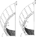
- the drive 100 includes a casing 102 extending along a drive axis 104 between a casing front end 106 and a casing rear end 108 spaced axially apart from the front end 106 in an axially rearward direction.
- a shaft 110 is rotatably supported in the casing 102 for rotation about the drive axis 104 in a circumferential first direction 112 (also referred to as forward direction 112).
- a disc pack 114 is supported in the casing 102 coaxial with the shaft 110 and is fixed to rotate therewith.
- the disc pack 114 includes a plurality of axially spaced apart discs 116.
- the discs 116 are generally annular.
- the discs 116 are spaced axially apart from one another by disc spaces 118.
- the disc spaces 118 define a plurality of compression chambers 120, and a plurality of turbine chambers 122 alternating axially with and in fluid isolation of the compression chambers 120.
- the drive 100 further includes a first manifold 128 (also referred to as hub manifold 128 or bore manifold 128) in the casing 102 radially inward of the disc pack 114.
- the hub manifold 128 includes a hub first ductwork 130 (also referred to as compression chamber inlet ductwork 130) for fluid communication with the compression chambers 120.
- the compression chamber inlet ductwork 130 is in fluid communication with the compression chambers 120 for conducting a first fluid into the compression chambers 120 to compress the first fluid during rotation of the disc pack 114 in the forward direction 112.
- the first fluid can include, for example, air.
- the hub manifold 128 includes a hub second ductwork 132 (also referred to as turbine chamber outlet ductwork 132) for fluid communication with the turbine chambers 122.
- the turbine chamber outlet ductwork 132 is in fluid communication with the turbine chambers 122 for evacuating a second fluid from the turbine chambers 122.
- the second fluid has a temperature greater than the first fluid, and can include, for example, combustion gases.
- the compression chamber inlet ductwork 130 and the turbine chamber outlet ductwork 132 are in fluid isolation of one another.
- the drive 100 further includes a second manifold 138 (also referred to as shroud manifold 138) in the casing 102 radially outward of the disc pack 114.
- the shroud manifold 138 includes a shroud first ductwork 140 (also referred to as a turbine chamber inlet ductwork 140) in fluid communication with the turbine chambers 122.
- the turbine chamber inlet ductwork 140 is in fluid communication with the turbine chambers 122 for conducting the second fluid into the turbine chambers 122 to urge rotation of the disc pack 114 in the forward direction 112.
- the shroud manifold 138 further includes a shroud second ductwork 142 (also referred to as compression chamber outlet ductwork 142) in fluid communication with the compression chambers 120.
- the compression chamber outlet ductwork 142 is in fluid communication with the compression chambers 120 for evacuating the first fluid from the compression chambers 120.
- the turbine chamber inlet ductwork 140 and the compression chamber outlet ductwork 142 are in fluid isolation of one another.
- At least one of the hub manifold and the shroud manifold can be fixed to rotate with the shaft about the drive axis.
- the hub manifold 128 is fixed to rotate with the shaft 110 about the drive axis 104, and forms part of the rotor assembly of the drive 100.
- the hub manifold 128 includes a hub body 150 coaxial with the drive axis, and each of the compression chamber inlet ductwork 130 and the turbine chamber outlet ductwork 132 are internal the hub body 150 (see also Figures 6A, 6B ).
- Providing the ductwork internal the manifold body can allow for optimization of the ductwork geometry to, for example, help condition fluid flow, minimize fluid losses, accommodate fluid flow fields at the manifold interfaces, control flow distribution among the working chambers, and control heat transfer between fluids passing through the ductwork.
- the hub body 150 is generally cylindrical.
- the hub body 150 includes a hub body first endface 150a and a hub body second endface 150b axially opposite the hub body first endface 150a.
- the hub body first endface 150a is located toward the casing front end 106, and the hub body second endface 150b is spaced apart from the hub body first endface 150a toward the casing rear end 108.
- the hub body 150 includes a hub body outer surface 152 directed radially outwardly toward the disc pack 114 and extending axially between the hub body first and second endfaces 150a, 150b.
- the disc spaces 118 are bounded radially by the hub body outer surface 152.
- the hub body 150 includes a radially inwardly directed hub body inner surface 154 radially opposite the hub body outer surface 152 and extending axially between the hub body first and second endfaces 150a, 150b.
- the hub manifold 128 includes a hub manifold bore 156 in the hub body 150 coaxial with the drive axis 104, and bounded radially by the hub body inner surface 154.
- the compression chamber inlet ductwork 130 includes a plurality of hub first ports 160 (also referred to as compression chamber inlet ports 160) open to the hub body outer surface 152 for discharging the first fluid from the compression chamber inlet ductwork 130 into the compression chambers 120.
- the turbine chamber outlet ductwork 132 includes a plurality of hub second ports 162 (also referred to as turbine chamber outlet ports 162) open to the hub body outer surface 152 for evacuating the second fluid from the turbine chambers 122 and into the turbine chamber outlet ductwork 132.
- the compression chamber inlet ports 160 are arranged in axially spaced apart hub first sets 160a (also referred to as hub inlet sets 160a), with each set 160a of compression chamber inlet ports 160 open to a respective compression chamber 120.
- the turbine chamber outlet ports 162 are arranged in axially spaced apart hub second sets 162a (also referred to as hub outlet sets 162a), with each set 162a of turbine chamber outlet ports 162 open to a respective turbine chamber 122.
- the hub outlet sets 162a alternate axially with the hub inlet sets 160a.
- the compression chamber inlet ports 160 in each set 160a are spaced circumferentially apart from one another about the drive axis 104.
- the compression chamber inlet ports 160 in each set 160a lie in a common hub first plane 163a oriented normal to the drive axis 104 (see also Figure 6C ).
- the turbine chamber outlet ports 162 in each set 162a are spaced circumferentially apart from one another about the drive axis 104.
- the turbine chamber outlet ports 162 in each set 162a lie in a common hub second plane 163b normal to the drive axis 104 (see also Figure 6C ).
- the compression chamber inlet ductwork 130 includes a plurality of circumferentially spaced apart hub headers 164 in fluid communication with the compression chamber inlet ports 160.
- each hub header 164 extends along a hub header centerline 165 between a hub header first end 164a open to the hub body first endface 150a for receiving the first fluid, and a hub header second end 164b spaced axially apart from the hub header first end 164a toward the hub body second endface 150b (see also Figures 2B and 4B ).
- each header 164 has a cross sectional area perpendicular to the drive axis 104. In the example illustrated, the cross-sectional area of each header 164 decreases along the header centerline 165 from the header first end 164a toward the header second end 164b.
- the hub manifold 128 includes a plurality of hub aerodynamic features 134 (see also Figure 8 ) extending at least partially across the header first ends 164a and fixed to rotate with the hub body 150 for conditioning flow of the first fluid entering the header first ends 164a.
- the aerodynamic features 134 comprise hub airfoils 136.
- the hub airfoils 136 are spaced circumferentially apart from one another about the drive axis 104 and extend radially across respective header first ends 164a (see also Figure 8 ).
- the compression chamber inlet ductwork 130 includes a plurality of hub first conduits 166 (also referred to as hub inlet conduits 166) for conducting the first fluid from the hub headers 164 to the compression chamber inlet ports 160.
- each hub inlet conduit 166 extends along a hub inlet conduit centerline 167 between a respective compression chamber inlet port 160 and a hub first conduit end 166a (also referred to as a hub inlet conduit intake end 166a) open to a respective hub header 164.
- the hub inlet conduit centerline 167 curves circumferentially between the compression chamber inlet port 160 and the hub first conduit end 166a.
- the inlet conduit centerline 167 extends from the inlet conduit intake end 166a to the compression chamber inlet port 160 in a circumferential second direction (also referred to as a reverse direction) opposite the forward direction 112 for directing fluid passing radially outwardly through the inlet conduit 166 in the reverse direction.
- This can help provide an inflow velocity of the first fluid corresponding to the developed flow field in the radially inner portion of the compression chambers 120, and may help improve compression efficiency.
- a second-fluid evacuation space 170 is provided in the casing 102 for receiving the second fluid discharged from the hub manifold 128, and evacuating the second fluid from the casing 102.
- the second-fluid evacuation space 170 is provided in the hub manifold bore 156.
- the turbine chamber outlet ductwork 132 includes a plurality of hub second conduits 168 (also referred to as hub outlet conduits 168) for conducting the second fluid from the turbine chamber outlet ports 162 to the second-fluid evacuation space 170.
- each outlet conduit 168 extends along a hub second conduit centerline 169 (also referred to as a hub outlet conduit centerline 169) between a respective turbine chamber outlet port 162 and a hub second conduit end 169a (also referred to as a hub outlet conduit discharge end 169a).
- the hub outlet conduit discharge end 169a is open to the hub body inner surface 154 (and the hub manifold bore 156, see Figure 3 ) and is in fluid communication with the evacuation space 170.
- the hub outlet conduit centerline 169 curves circumferentially between the turbine chamber outlet port 162 and the hub second conduit end 169a.
- the outlet conduit centerline 169 extends from the turbine chamber outlet port 162 to the outlet conduit discharge end 169a in the circumferential forward direction 112 for directing the second fluid passing radially inwardly through the hub outlet conduit 168 in the forward direction 112. This can help provide an outlet curvature having an intake portion corresponding to the developed flow field in the radially inner portion of the turbine chambers.
- the second fluid can be evacuated through the second-fluid evacuation space 170 in an axial direction.
- the second fluid is evacuated through the evacuation space 170 in the axially forward direction.
- the shaft 110 includes a shaft body 172 in the hub manifold bore 156, and a shaft bore 174 in the shaft body 172 coaxial with the drive axis 104.
- the shaft bore 174 comprises the second-fluid evacuation space 170.
- the shaft 110 includes a plurality of shaft ports 176 extending radially through the shaft body 172 and between respective hub outlet conduits 168 and the second-fluid evacuation space 170 for conducting the second fluid from the outlet conduits 168 to the evacuation space 170.
- At least a portion of the hub body 150 is formed of a thermally conductive material for conductively transferring heat between the first fluid passing through the compression chamber inlet ductwork 130 and the second fluid passing through the turbine chamber outlet ductwork 132.
- the shroud manifold 138 is fixed to rotate with the shaft 110 about the drive axis 104, and forms part of the rotor assembly of the drive 100.
- the shroud manifold 138 includes a shroud body 180 coaxial with the drive axis 104, and each of the turbine chamber inlet ductwork 140 and the compression chamber outlet ductwork 142 is internal the shroud body 180.
- the shroud body 180 is generally cylindrical.
- the shroud body 180 includes a shroud body first endface 180a, and a shroud body second endface 180b axially opposite the shroud body first endface 180a (see also Figures 2A and 2C ).
- the shroud body first endface 180a is located toward the casing rear end 108, and the shroud body second endface 180b is spaced apart from the shroud body first endface 180a toward the casing front end 106.
- the shroud body 180 includes a shroud body inner surface 184 directed radially inwardly toward the disc pack 114 and extending axially between the first and second endfaces 180a, 180b.
- the shroud body 180 includes a radially outwardly directed shroud body outer surface 182 radially opposite the shroud body inner surface 184 and extending axially between the shroud body first and second endfaces 180a, 180b.
- the shroud manifold 138 includes a shroud manifold bore 186 in the shroud body 180 coaxial with the drive axis 104, and bounded radially by the shroud body inner surface 184.
- the shroud manifold bore 186 is sized to receive the disc pack 114 therein, and the disc spaces 118 are bounded radially by the shroud body inner surface 184.
- the turbine chamber inlet ductwork 140 includes a plurality of shroud first ports 190 (also referred to as turbine chamber inlet ports 190) open to the shroud body inner surface 184 for discharging the second fluid from the turbine chamber inlet ductwork 140 and into the turbine chambers 122 to urge rotation of the disc pack 114 in the forward direction 112.
- the compression chamber outlet ductwork 142 includes a plurality of shroud second ports 192 (also referred to as compression chamber outlet ports 192) open to the body inner surface 184 for evacuating the first fluid from the compression chambers 120 and into the compression chamber outlet ductwork 142.
- the plurality of turbine chamber inlet ports 190 are arranged in axially spaced apart shroud first sets 190a (also referred to as shroud inlet sets 190a), with each set 190a of turbine chamber inlet ports 190 open to a respective turbine chamber 122.
- the plurality of compression chamber outlet ports 192 are arranged in axially spaced apart shroud second sets 192a (also referred to as shroud outlet sets 192a), with each set of compression chamber outlet ports 192 open to a respective compression chamber 120.
- the shroud inlet sets 190a alternate axially with the shroud outlet sets 192a.
- the turbine chamber inlet ports 190 in each set 190a are spaced circumferentially apart from one another about the drive axis 104.
- the turbine chamber inlet ports 190 in each set 190a lie in a common shroud first plane 193a oriented normal to the drive axis 104.
- each shroud first plane 193a is coincident with a respective hub second plane 163b, and the turbine chamber inlet ports 190 open to a respective turbine chamber 122 are generally in axial alignment with the turbine chamber outlet ports 162 open to that same turbine chamber 122.
- each set 192a are spaced circumferentially apart from one another about the drive axis 104.
- the compression chamber outlet ports 192 in each set 192a lie in a common shroud second plane 193b oriented normal to the drive axis.
- each shroud second plane 193b is coincident with a respective hub first plane 163a, and the compression chamber outlet ports 192 open to a respective compression chamber 120 are generally in axial alignment with the compression chamber inlet ports 160 open to that same compression chamber 120.
- the turbine chamber inlet ductwork 140 includes a plurality of circumferentially spaced apart shroud headers 194 in fluid communication with the turbine chamber inlet ports 190 (see also Figure 5A ).
- Each shroud header 194 extends along a shroud header centerline 195 between a shroud header first end 194a open to the shroud body first endface 180a for receiving the second fluid and a shroud header second end 194b spaced axially apart from the shroud header first end 194a toward the shroud body second endface 180b.
- the shroud header centerline 195 extends generally parallel to the drive axis 104.
- the shroud manifold 138 includes a plurality of shroud aerodynamic features 144 extending at least partially across the shroud header first ends 194a and fixed to rotate with the shroud body 180 for conditioning flow of the second fluid entering the shroud headers 194.
- the shroud aerodynamic features 144 comprise shroud airfoils 146.
- the shroud airfoils 146 are spaced circumferentially apart from one another about the drive axis 104 and extend radially across respective shroud header first ends 194a.
- the turbine chamber inlet ductwork 140 includes a plurality of shroud first conduits 196 (also referred to as shroud inlet conduits 196) for conducting the second fluid from the shroud headers 194 to the turbine chamber inlet ports 190.
- each shroud inlet conduit 196 extends along a shroud first conduit centerline 197 (also referred to as shroud inlet conduit centerline 197) between a respective turbine chamber inlet port 190 and a shroud first conduit end 196a (also referred to as a shroud inlet conduit intake end 196a) open to a respective shroud header 194.
- the shroud inlet conduit centerline 197 curves circumferentially between the turbine chamber inlet port 190 and the shroud inlet conduit intake end 196a.
- the shroud inlet conduit centerline 197 extends from the inlet conduit intake end 196a to the turbine chamber inlet port 190 in the circumferential forward direction 112 for directing fluid passing radially inwardly through the shroud inlet conduit 196 and into a respective turbine chamber 122 in the forward direction 112 to urge rotation of the disc pack 114.
- a first-fluid evacuation space 178 is provided in the casing 102 for receiving the first fluid discharged from the shroud manifold 138, and evacuating the first fluid from the casing 102.
- the first-fluid evacuation space 178 is radially intermediate the shroud manifold 138 and an inner surface 103 of the casing 102.
- the first-fluid evacuation space 178 is bounded radially by the shroud body outer surface 182.
- the first fluid can be evacuated through the first-fluid evacuation space 178 in an axial direction.
- the second fluid is evacuated through the evacuation space 178 in the axially rearward direction.
- the first-fluid evacuation space 178 can comprise a vaneless space open to a semi-vaneless space in the casing for facilitating diffusion of the first fluid.
- the compression chamber outlet ductwork 142 includes a plurality of shroud second conduits 198 (also referred to as shroud outlet conduits 198) for conducting the first fluid from the compression chamber outlet ports 192 to the first-fluid evacuation space 178.
- each outlet conduit 198 extends along a shroud outlet conduit centerline 199 between a respective compression chamber outlet port 192 and a shroud second conduit end 198a (also referred to as a shroud outlet conduit discharge end 198a) open to the shroud body outer surface 182 and in fluid communication with the first-fluid evacuation space 178.
- the shroud outlet conduit centerline 199 curves circumferentially between the chamber outlet port 192 and the shroud outlet conduit discharge end 198a.
- the shroud outlet conduit 198 includes an intake portion 200 extending along an intake portion centerline 201 from the compression chamber outlet port 192 toward the outlet conduit discharge end 198a.
- the intake portion centerline 201 curves circumferentially from the compression chamber outlet port 192 toward the outlet conduit discharge end 198a.
- the intake portion centerline 201 extends from the compression chamber outlet port 192 toward the outlet conduit discharge end 198a in the circumferential reverse direction (opposite the forward direction 112) for directing the first fluid entering and passing radially outwardly through the intake portion 200 in the reverse direction. This can help accommodate the developed flow field in the radially outer portion of the compression chambers.
- the shroud outlet conduit 198 includes a discharge portion 202 extending along a discharge portion centerline 203 from the intake portion 200 to the outlet conduit discharge end 198a.
- the discharge portion centerline 203 curves circumferentially from the intake portion 200 to the outlet conduit discharge end 198a.
- the discharge centerline 203 and the intake portion centerline 201 can curve in circumferentially opposite directions.
- the discharge portion centerline 203 can extend from the intake portion 200 to the outlet conduit discharge end 198a in one of the circumferential forward direction 112 and the reverse direction for directing the first fluid passing radially outwardly through the discharge portion 202 and into the evacuation space 178 in the one of the forward direction 112 and the reverse direction.
- the discharge portion centerline 203 extends from the intake portion 200 to the outlet conduit discharge end 198a in the circumferential forward direction 112 for directing the first fluid passing radially outwardly through the discharge portion 202 and into the evacuation space 178 in the forward direction 112. This can help machine performance.
- the drive 100 can include one or more disc mounting features.
- the disc mounting features can, for example, facilitate axial positioning of the discs 116 and/or rotational locking of the disc pack 114 with one or both of the hub manifold 128 and the shroud manifold 138.
- the disc mounting features can include, for example, weldments, keys, keyways, and/or spacers.
- the disc pack can be bonded (e.g. welded or adhered) to one or both of the hub manifold body and the shroud manifold body to rotationally lock the disc pack 114 thereto.
- the disc mounting features include a plurality of axially spaced apart circumferential shroud grooves 204 in the shroud body inner surface 184.
- Each shroud groove 204 is axially intermediate a respective shroud inlet set 190a of turbine chamber inlet ports 190, and a respective axially adjacent shroud outlet set 192a of compression chamber outlet ports 192.
- each shroud groove 204 receives a radially outer peripheral edge of a respective disc 116 to facilitate axial positioning of the discs 116.
- the disc mounting feature further includes a plurality of axially spaced apart circumferential hub grooves 205 (shown schematically in Figure 6C -see also grooves 1205 in Figures 9A and 9B ) in the hub body outer surface 152.
- Each hub groove 205 is axially intermediate a respective hub inlet set 160a of compression chamber inlet ports 160 and a respective axially adjacent hub outlet set 162a of turbine chamber outlet ports 162.
- Each hub groove 205 can receive a radially inner peripheral edge of a respective disc 116 to facilitate axial positioning of the discs.
- the shroud and hub grooves 204, 205 are in axial alignment with one another.
- the discs 116 can be positioned into the shroud grooves 204 through, for example, thermal expansion of the shroud body 180 relative to the discs 116 and/or thermal contraction of the discs 116 relative to the shroud body 180.
- the discs 116 can be positioned into the hub grooves 205 through, for example, thermal contraction of the hub body 150 relative to the discs 116 and/or thermal expansion of the discs 116 relative to the hub body 150.
- the disc mounting feature includes an interference structure for engagement with the disc pack 114 to rotationally lock the disc pack 114 with one or both of the hub manifold 128 and the shroud manifold 138.
- the interference structure can comprise, for example, axially facing groove surfaces of the shroud grooves 204 and/or the hub grooves 205 for providing an interference fit with the discs 116.
- the interference structure can include, for example, protrusions, pins, and/or keys for engagement with corresponding recesses, apertures, and/or keyways in one or more discs 116 to rotationally lock the disc pack 114 with one or both of the hub manifold 128 and the shroud manifold 138.
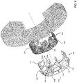
- the hub body 150 includes a core 206 coaxial with the drive axis 104 and through which at least a portion of the compression chamber inlet ductwork 130 and the turbine chamber outlet ductwork 132 passes.
- the hub headers 164, hub inlet conduits 166, and hub outlet conduits 168 pass through the core 206 (see also Figure 4B ).
- the core 206 is of integral, unitary, one-piece construction.
- the core 206 can be formed using, for example, a 3D printing or casting process which can help provide for complex ductwork geometry internal the core 206. In some cases, components formed using such processes may have limited structural integrity and/or material properties that may be less than ideal for rotary applications involving high rotational and/or thermal stresses.
- the hub body 150 includes a frame 208 mounted to the core 206 for exerting an inwardly directed force on the core 206 to regulate a stress distribution therein during operation (see also Figures 6A and 6B ). This can help improve, for example, the operating range and/or life expectancy of the core 206.
- the core 206 has a radially outwardly directed core outer surface 210
- the frame 208 includes an outer sleeve 212 mounted over the core 206 and in engagement with the core outer surface 210 for inducing radial compression of the core 206 during operation.
- the outer sleeve 212 comprises the hub body outer surface 152.
- the outer sleeve 212 can induce radial compression through, for example, an interference fit with the core outer surface 210, and/or through a clamping assembly.
- the frame 208 includes a plurality of anchors 214.
- Each anchor 214 extends between an anchor outer end 214a fixed to the outer sleeve 212 and an anchor inner end 214b fixed to the shaft 110 for inducing radial compression of the core 206.
- the hub body 150 includes a plurality of apertures 216 passing radially through the core 206, and the anchors 214 extend through respective apertures 216. This can facilitate alignment between the ductwork portions passing through the outer sleeve 212 and the ductwork portions internal the core 206, and between the shaft ports 176 and the ductwork portions internal the core 206.
- the core 206 has a core first endface 206a and a core second endface 206b axially opposite the core first endface 206a.
- the frame 208 includes a first end cap 218a in engagement with the core first endface 206a, and a second end cap 218b in engagement with the core second endface 206b.
- the first and second end caps 218a, 218b can be anchored to one another for inducing axial compression of the core 206 during operation.
- the first and second end caps 218a, 218b are anchored to one another via the outer sleeve 212.
- each of the first and second endcaps 218a, 218b has a radially outer endcap portion 220 fixed to the outer sleeve 212 and the disc pack 114, a radially inner endcap portion 222 fixed to the shaft 110, and a radially intermediate endcap portion 224 connecting the radially outer endcap portion 220 and the radially inner endcap portion 222.
- the frame 208 includes a disc pack mounting portion 226 for engagement with the disc pack 114 to fix the disc pack to the hub body 150.
- the disc pack mounting portion 226 can include the outer sleeve 212, and/or the radially outer endcap portions 220.
- the frame 208 includes a shaft mounting portion 228 for engagement with the shaft 110 to fix the shaft 110 to the frame 208.
- the shaft mounting portion 228 is spaced radially inwardly apart from the disc pack mounting portion 226.
- the shaft mounting portion 228 includes the radially inner endcap portions 222.
- the frame 208 includes one or more torque-transfer members 230 for transferring torque between the disc pack mounting portion 226 and the shaft mounting portion 228.
- each torque-transfer member 230 has a radially outer end 230a fixed to the disc pack mounting portion 226 and a radially inner end 230b fixed to the shaft mounting portion 228.
- the torque-transfer members 230 include the radially intermediate endcap portions 224.
- hub aerodynamic features 134 are mounted to the frame 208.
- FIGS 9A-9B an example of another hub manifold 1128 for a rotor assembly of a cohesion-type drive is illustrated.
- the manifold 1128 has similarities to the hub manifold 128, and like features are identified by like reference characters, incremented by 1000.
- the manifold 1128 includes a manifold body 1150 extending along a drive axis 1104 for rotation thereabout.
- the body 1150 includes a first endface 1150a, a second endface axially opposite the first endface 1150a, and a radially outwardly directed body outer surface 1152 extending between the first and second endfaces 1150a, 1150b.
- the body is of integral, unitary, one-piece construction.
- the hub manifold includes a plurality of grooves 1205 in the body outer surface 1152 for receiving radially inner peripheral edges of discs of the drive to facilitate mounting of the discs.
- the drive 2100 includes a hub manifold 2128 having a manifold body 2150 extending along a drive axis 2104 for rotation thereabout.
- the body 2150 includes a first endface 2150a, a second endface 2150b axially opposite the first endface 2150a, a radially outwardly directed outer surface 2152 extending between the first and second endfaces 2150a, 2150b, and a radially inwardly directly inner surface 2154 radially opposite the outer surface 2152.
- the body 2150 is tapered radially along the drive axis 2104. This can allow for a variation in an inner radius of the first and second working chambers 2120, 2122 along the drive axis 2104, and can facilitate optimization of, for example, mass flow and work.
- the outer surface 2152 is spaced radially apart from the drive axis by a body outer radius 2232.
- the body outer radius 2232 decreases along the drive axis 2104 from the first endface 2150a toward the second endface 2150b of the body 2150.
- the inner surface 2154 is spaced radially apart from the drive axis 2104 by a body inner radius 2234.
- the body inner radius 2234 decreases along the drive axis 2104 from the first endface 2150a toward the second endface 2150b of the body 2150.
- FIG. 11 an example of another manifold 3128 for a rotor assembly of a cohesion-type drive is illustrated schematically.
- the manifold 3128 has similarities to the hub manifold 128, and like feature are identified by like reference characters, incremented by 3000.
- the manifold 3128 includes a manifold body 3150 extending along a drive axis 3104 for rotation thereabout.
- the body 3150 includes a core 3206 coaxial with the drive axis 3104, and a frame 3208 mounted to the core 3206 for exerting an inwardly directed force on the core 3206 to regulate a stress distribution therein during operation of the drive.
- the manifold body 3150 includes ductwork internal the body 3150 for fluid communication with a plurality of working chambers of the drive. At least a portion of the ductwork passes through the core 3206.
- the core 3206 has a radially outwardly directed core outer surface 3210
- the frame 3208 includes an outer sleeve 3212 mounted over the core 3206 and in engagement with the core outer surface 3210 for inducing radial compression of the core 3206 during operation.
- the body 3150 includes a core bore 3238 in the core 3206 coaxial with the drive axis 3104 and bounded by a radially inwardly directed core inner surface 3239 of the core 3206.
- the frame 3208 includes an inner sleeve 3240 in the core bore 3238 and in engagement with the core inner surface 3239.
- the outer and inner sleeves 3212, 3240 are anchored to one another for inducing radial compression of the core 3206 during operation.
- the outer sleeve 3212 comprises a body outer surface 3152 of the manifold body 3150
- the inner sleeve 3240 comprises a body inner surface 3154 of the manifold body 3150.
- the frame 3208 includes a plurality of anchors 3214 anchoring the outer and inner sleeves 3212, 3240 to one another.
- Each anchor 3214 extends between an anchor outer end 3214a fixed to the outer sleeve 3212 and an anchor inner end 3214b fixed to the inner sleeve 3240.
- the anchor outer ends 3214a are axially offset from the anchor inner ends 3214b.
- the manifold body 3150 includes a plurality of apertures passing radially through the core 3206 between the core outer and inner surfaces 3210, 3239, and the anchors extend through respective apertures.
- the core 3206 has a core first endface 3206a and a core second endface 3206b axially opposite the core first endface 3206a.
- the frame 3208 includes a first end cap 3218a in engagement with the core first endface 3206a and a second end cap 3218b in engagement with the core second endface 3206b.
- the first and second end caps 3218a, 3218b are anchored to one another for inducing axial compression of the core 3206 during operation.
- the first and second end caps 3218a, 3218b are anchored to one another via the outer and inner sleeves 3212, 3240.
- the frame 3208 includes a disc pack mounting portion 3226 for engagement with the disc pack 3114 to fix the disc pack to the frame 3208.
- the disc pack mounting portion 3226 can include the outer sleeve 3212, and/or radially outer endcap portions.
- the frame 3208 includes a shaft mounting portion 3228 for engagement with the shaft 3110 to fix the shaft 3110 to the frame 3208.
- the shaft mounting portion 3228 is spaced radially inwardly from the disc pack mounting portion 3226.
- the shaft mounting portion 3228 can include the inner sleeve 3240 and/or radially inner endcap portions.
- the frame 3208 includes one or more torque-transfer members 3230 for transferring torque between the disc pack mounting portion 3226 and the shaft mounting portion 3228.
- Each torque-transfer member 3230 has a radially outer end 3230a fixed to the disc pack mounting portion 3226 and a radially inner end 3230b fixed to the shaft mounting portion 3228.
- the torque-transfer members 3230 include radially intermediate endcap portions 3224.
- charts A-D show the difference in stress distribution for a hollow rotating disc with and without imposed radial loads at the inner and outer radiuses.
- the charts A-D show radial, hoop, and shear stress distribution in the rotating disc for the four different boundary conditions outlined in Table 1 of Figure 12 .
- the stresses are radial and normalized by a factor of ( ⁇ ) 2 )/8, with a positive stress indicating a tensile load.
- Radial and hoop stresses are shown in solid lines, and shear stress is shown in dashed lines.
Landscapes
- Engineering & Computer Science (AREA)
- Mechanical Engineering (AREA)
- General Engineering & Computer Science (AREA)
- Chemical & Material Sciences (AREA)
- Combustion & Propulsion (AREA)
- Structures Of Non-Positive Displacement Pumps (AREA)
Claims (15)
- Entraînement de type cohésion (100), comprenant :a) un carter (102) ;b) un arbre (110) supporté de manière rotative dans le carter pour tourner autour d'un axe d'entraînement (104) dans une direction avant circonférentielle ;c) un paquet de disques (114) supporté dans le carter, coaxial avec l'arbre et fixé pour tourner avec celui-ci, le paquet de disques comportant une pluralité de disques (116) espacés axialement les uns des autres par des espaces de disques (118), les espaces de disques comprenant une pluralité de chambres de compression (120) et une pluralité de chambres de turbine (122), les chambres de turbine alternant axialement avec les chambres de compression et de manière isolée fluidiquement de celles-ci ;d) un collecteur de moyeu (128) dans le carter radialement dans le paquet de disques, le collecteur de moyeu comportant : un corps de moyeu (150) coaxial avec l'axe d'entraînement, un réseau de conduites d'entrée de chambre de compression (130) dans le corps de moyeu et en communication fluidique avec les chambres de compression pour conduire un premier fluide dans les chambres de compression afin de comprimer le premier fluide pendant la rotation du paquet de disques dans la direction avant, et un réseau de conduites de sortie de chambre de turbine (132) dans le corps de moyeu et en communication fluidique avec les chambres de turbine pour évacuer un second fluide des chambres de turbine, le réseau de conduites de sortie de chambre de turbine étant isolé fluidiquement du réseau de conduites d'entrée de chambre de compression ; ete) un collecteur d'enveloppe (138) dans le carter radialement à l'extérieur du paquet de disques, le collecteur d'enveloppe comportant : un corps d'enveloppe coaxial avec l'axe d'entraînement, un réseau de conduites de sortie de chambre de compression (142) à l'intérieur du corps d'enveloppe et en communication fluidique avec les chambres de compression pour évacuer le premier fluide des chambres de compression, et un réseau de conduites d'entrée de chambre de turbine (140) dans le corps d'enveloppe et en communication fluidique avec les chambres de turbine pour conduire le second fluide dans les chambres de turbine pour solliciter la rotation du paquet de disques dans la direction avant, le réseau de conduites d'entrée de chambre de turbine étant isolé fluidiquement du réseau de conduites de sortie de chambre de compression, dans lequel au moins l'un du collecteur de moyeu et du collecteur d'enveloppe est fixé pour tourner avec l'arbre autour de l'axe.
- Entraînement selon la revendication 1, dans lequel le collecteur de moyeu est fixé pour tourner avec l'arbre autour de l'axe d'entraînement.
- Entraînement selon la revendication 2, dans lequel le corps de moyeu comporte une première face d'extrémité de corps de moyeu (150a), une seconde face d'extrémité de corps de moyeu (150b) axialement opposée à la première face d'extrémité de corps de moyeu, et une surface extérieure de corps de moyeu (152) s'étendant entre les première et seconde faces d'extrémité de corps de moyeu et dirigée radialement vers l'extérieur en direction du paquet de disques, les espaces de disques étant délimités radialement par la surface extérieure de corps de moyeu, et dans lequel le réseau de conduites d'entrée de chambre de compression comporte une pluralité d'orifices d'entrée de chambre de compression (160) ouverts sur la surface extérieure de corps de moyeu pour décharger le premier fluide du réseau de conduites d'entrée de chambre de compression dans les chambres de compression, et le réseau de conduites de sortie de chambre de turbine comporte une pluralité d'orifices de sortie de chambre de turbine (162) ouverts sur la surface extérieure de corps de moyeu pour évacuer le second fluide des chambres de turbine et dans le réseau de conduites de sortie de chambre de turbine.
- Entraînement selon la revendication 3, dans lequel le réseau de conduites d'entrée de chambre de compression comporte une pluralité d'embases de moyeu (164) espacées circonférentiellement en communication fluidique avec les orifices d'entrée de chambre de compression, chaque embase de moyeu s'étendant le long d'une ligne centrale d'embase de moyeu (165) entre une première extrémité d'embase de moyeu (164a) ouverte sur la première face d'extrémité de corps de moyeu pour recevoir le premier fluide et une seconde extrémité d'embase de moyeu (164b) espacée axialement de la première extrémité d'embase de moyeu en direction de la seconde face d'extrémité de corps de moyeu ; et éventuellement, dans lequel la ligne centrale d'embase de moyeu s'étend de manière hélicoïdale autour de l'axe d'entraînement dans la direction avant circonférentielle à partir de la première extrémité d'embase de moyeu vers la seconde extrémité d'embase de moyeu ; et éventuellement, dans lequel chaque embase de moyeu a une surface de section transversale perpendiculaire à l'axe d'entraînement, la surface de section transversale de chaque embase de moyeu diminuant le long de la ligne centrale d'embase de moyeu à partir de la première extrémité d'embase de moyeu vers la seconde extrémité d'embase de moyeu.
- Entraînement selon la revendication 4, dans lequel le collecteur de moyeu comporte une pluralité d'éléments aérodynamiques de moyeu (134) s'étendant au moins partiellement sur les premières extrémités d'embase de moyeu et fixées pour tourner avec le corps de moyeu pour traiter l'écoulement du premier fluide entrant dans les premières extrémités d'embase de moyeu.
- Entraînement selon l'une quelconque des revendications 4 à 5, dans lequel le réseau de conduites d'entrée de chambre de compression comporte une pluralité de conduites d'entrée de moyeu (166) pour conduire le premier fluide à partir des embases de moyeu vers les orifices d'entrée de chambre de compression, chaque conduite d'entrée de moyeu s'étendant le long d'une ligne centrale de conduite d'entrée de moyeu (167) entre un orifice d'entrée de chambre de compression respectif et une extrémité d'admission de conduite d'entrée de moyeu (166a) ouverte sur une embase de moyeu respective ; et éventuellement, dans lequel la ligne centrale de conduite d'entrée de moyeu se courbe circonférentiellement entre l'orifice d'entrée de chambre de compression et l'extrémité d'admission de conduite d'entrée de moyeu.
- Entraînement selon l'une quelconque des revendications 3 à 6, dans lequel le corps de moyeu comporte une surface intérieure de corps de moyeu (154) radialement opposée à la surface extérieure de corps de moyeu, et un trou de collecteur (156) coaxial avec l'axe d'entraînement et délimité radialement par la surface intérieure de corps de moyeu, et dans lequel le réseau de conduites de sortie de chambre de turbine comporte une pluralité de conduites de sortie de moyeu (168) pour conduire le second fluide à partir des orifices de sortie de chambre de turbine vers un espace d'évacuation de second fluide (170) prévu dans le trou de collecteur, chaque conduite de sortie de moyeu s'étendant le long d'une ligne centrale de conduite de sortie de moyeu (169) entre un orifice de sortie de chambre de turbine respectif et une extrémité de décharge de conduite de sortie de moyeu (169a) ouverte sur la surface intérieure de corps de moyeu et en communication fluidique avec l'espace d'évacuation de second fluide ; et éventuellement, dans lequel la ligne centrale de conduite de sortie de moyeu se courbe circonférentiellement entre l'orifice de sortie de chambre de turbine et l'extrémité de décharge de conduite de sortie de moyeu.
- Entraînement selon l'une quelconque des revendications 3 à 7, dans lequel la pluralité d'orifices d'entrée de chambre de compression sont disposés dans des ensembles d'entrée de moyeu (160a) espacés axialement, les orifices d'entrée de chambre de compression dans chaque ensemble étant espacés circonférentiellement les uns des autres autour de l'axe d'entraînement et ouverts sur une chambre de compression respective, et dans lequel la pluralité d'orifices de sortie de chambre de turbine sont disposés dans des ensembles de sortie de moyeu (162a) espacés axialement alternant axialement avec les ensembles d'entrée, les orifices de sortie de chambre de turbine dans chaque ensemble étant espacés circonférentiellement les uns des autres autour de l'axe d'entraînement et ouverts sur une chambre de turbine respective.
- Entraînement selon l'une quelconque des revendications 1 à 8, dans lequel le corps de moyeu comporte un noyau (206) coaxial avec l'axe d'entraînement et à travers lequel passe au moins une partie du réseau de conduites d'entrée de chambre de compression et du réseau de conduites de sortie de chambre de turbine, et un cadre (208) monté sur le noyau pour exercer une force dirigée vers l'intérieur sur le noyau pour réguler une distribution de contraintes dans celui-ci pendant le fonctionnement ; et éventuellement, dans lequel le noyau a une surface extérieure de noyau (210) dirigée radialement vers l'extérieur, et le cadre comporte un manchon extérieur (212) monté au-dessus du noyau et en prise avec la surface extérieure de noyau pour induire une compression radiale du noyau pendant le fonctionnement.
- Entraînement selon l'une quelconque des revendications 1 à 9, dans lequel le collecteur d'enveloppe est fixé pour tourner avec l'arbre autour de l'axe d'entraînement.
- Entraînement selon la revendication 10, dans lequel le corps d'enveloppe comporte une première face d'extrémité de corps d'enveloppe (180a), une seconde face d'extrémité de corps d'enveloppe (180b) axialement opposée à la première face d'extrémité de corps d'enveloppe, et une surface intérieure de corps d'enveloppe (184) s'étendant entre les première et seconde faces d'extrémité de corps d'enveloppe et dirigée radialement vers l'intérieur vers le paquet de disques, les espaces de disques étant délimités radialement par la surface intérieure de corps d'enveloppe, et dans lequel le réseau de conduites de sortie de chambre de compression comporte une pluralité d'orifices de sortie de chambre de compression (192) ouverts sur la surface intérieure de corps d'enveloppe pour évacuer le premier fluide des chambres de compression et dans le réseau de conduites d'entrée de chambre de compression, et le réseau de conduites d'entrée de chambre de turbine comporte une pluralité d'orifices d'entrée de chambre de turbine (190) ouverts sur la surface intérieure de corps d'enveloppe pour décharger le second fluide du réseau de conduites de sortie de chambre de turbine et dans les chambres de turbine pour solliciter la rotation du paquet de disques dans la direction avant.
- Entraînement selon la revendication 11, dans lequel le réseau de conduites d'entrée de chambre de turbine comporte une pluralité d'embases d'enveloppe (194) espacées circonférentiellement en communication fluidique avec les orifices d'entrée de chambre de turbine, chaque embase d'enveloppe s'étendant entre une première extrémité d'embase d'enveloppe (194a) ouverte sur la première face d'extrémité de corps d'enveloppe pour recevoir le second fluide et une seconde extrémité d'embase d'enveloppe (194b) espacée axialement de la première extrémité d'embase d'enveloppe vers la seconde face d'extrémité de corps d'enveloppe ; et éventuellement, dans lequel l'embase d'enveloppe comporte une pluralité d'éléments aérodynamiques d'enveloppe (144) s'étendant au moins partiellement sur les premières extrémités d'embase d'enveloppe et fixées pour tourner avec le corps d'enveloppe pour traiter l'écoulement du second fluide entrant dans les embases d'enveloppe.
- Entraînement selon la revendication 12, dans lequel le réseau de conduites d'entrée de chambre de turbine comporte une pluralité de conduites d'entrée d'enveloppe (196) pour conduire le second fluide à partir des embases d'enveloppe vers les orifices d'entrée de chambre de turbine, chaque conduite d'entrée d'enveloppe s'étendant le long d'une ligne centrale de conduite d'entrée d'enveloppe (197) entre un orifice d'entrée de chambre de turbine respectif et une extrémité d'admission de conduite d'entrée d'enveloppe (196a) ouverte sur une embase d'enveloppe respective ; et éventuellement, dans lequel la ligne centrale de conduite d'entrée d'enveloppe se courbe circonférentiellement entre l'orifice d'entrée de chambre de turbine et l'extrémité d'admission de conduite d'entrée d'enveloppe.
- Entraînement selon la revendication 13, dans lequel le corps d'enveloppe a une surface extérieure de corps d'enveloppe (182) radialement opposée à la surface intérieure de corps d'enveloppe, et l'entraînement comporte un espace d'évacuation de premier fluide (178) dans le carter radialement entre le collecteur d'enveloppe et une surface intérieure (103) du carter et délimité radialement par la surface extérieure de corps d'enveloppe pour évacuer le premier fluide, et dans lequel le réseau de conduites de sortie de chambre de compression comporte une pluralité de conduites de sortie d'enveloppe (198) pour conduire le premier fluide à partir des orifices de sortie de chambre de compression vers l'espace d'évacuation de premier fluide, chaque conduite de sortie d'enveloppe s'étendant le long d'une ligne centrale de conduite de sortie d'enveloppe (199) entre un orifice de sortie de chambre de compression respectif et une extrémité de décharge de conduite de sortie d'enveloppe (198a) ouverte sur la surface extérieure de corps d'enveloppe et en communication fluidique avec l'espace d'évacuation de premier fluide ; et éventuellement, dans lequel la ligne centrale de conduite de sortie d'enveloppe se courbe circonférentiellement entre l'orifice de sortie de chambre de compression et l'extrémité de décharge de conduite de sortie d'enveloppe.
- Entraînement selon l'une quelconque des revendications 11 à 14, dans lequel la pluralité d'orifices d'entrée de chambre de turbine sont disposés dans des ensembles d'entrée d'enveloppe (190a) espacés axialement, les orifices d'entrée de chambre de turbine dans chaque ensemble étant espacés circonférentiellement les uns des autres autour de l'axe d'entraînement et s'ouvrant sur une chambre de turbine respective, et dans lequel la pluralité d'orifices de sortie de chambre de compression sont disposés dans des ensembles de sortie d'enveloppe (192a) espacés axialement alternant axialement avec les ensembles d'entrée, les orifices de sortie de chambre de compression dans chaque ensemble étant espacés circonférentiellement les uns des autres autour de l'axe d'entraînement et s'ouvrant sur une chambre de compression respective.
Priority Applications (1)
| Application Number | Priority Date | Filing Date | Title |
|---|---|---|---|
| EP22184133.1A EP4144956B1 (fr) | 2016-11-23 | 2017-11-23 | Collecteur rotatif pour un entraînement de type à cohésion |
Applications Claiming Priority (3)
| Application Number | Priority Date | Filing Date | Title |
|---|---|---|---|
| US201662426122P | 2016-11-23 | 2016-11-23 | |
| US201662426109P | 2016-11-23 | 2016-11-23 | |
| PCT/CA2017/051406 WO2018094524A1 (fr) | 2016-11-23 | 2017-11-23 | Collecteur rotatif pour un entraînement de type à cohésion |
Related Child Applications (1)
| Application Number | Title | Priority Date | Filing Date |
|---|---|---|---|
| EP22184133.1A Division EP4144956B1 (fr) | 2016-11-23 | 2017-11-23 | Collecteur rotatif pour un entraînement de type à cohésion |
Publications (3)
| Publication Number | Publication Date |
|---|---|
| EP3545170A1 EP3545170A1 (fr) | 2019-10-02 |
| EP3545170A4 EP3545170A4 (fr) | 2020-06-24 |
| EP3545170B1 true EP3545170B1 (fr) | 2022-07-13 |
Family
ID=62144329
Family Applications (2)
| Application Number | Title | Priority Date | Filing Date |
|---|---|---|---|
| EP17873374.7A Active EP3545170B1 (fr) | 2016-11-23 | 2017-11-23 | Collecteur rotatif pour un entraînement de type à cohésion |
| EP22184133.1A Active EP4144956B1 (fr) | 2016-11-23 | 2017-11-23 | Collecteur rotatif pour un entraînement de type à cohésion |
Family Applications After (1)
| Application Number | Title | Priority Date | Filing Date |
|---|---|---|---|
| EP22184133.1A Active EP4144956B1 (fr) | 2016-11-23 | 2017-11-23 | Collecteur rotatif pour un entraînement de type à cohésion |
Country Status (4)
| Country | Link |
|---|---|
| US (3) | US10794239B2 (fr) |
| EP (2) | EP3545170B1 (fr) |
| CA (2) | CA3044481A1 (fr) |
| WO (1) | WO2018094524A1 (fr) |
Families Citing this family (5)
| Publication number | Priority date | Publication date | Assignee | Title |
|---|---|---|---|---|
| WO2018094524A1 (fr) * | 2016-11-23 | 2018-05-31 | McGuire Aero Propulsion Solutions Inc. | Collecteur rotatif pour un entraînement de type à cohésion |
| IT201800007430A1 (it) * | 2018-07-23 | 2020-01-23 | Macchina per la generazione di energia mediante sfruttamento del flusso di un fluido | |
| CN113982752B (zh) * | 2021-10-30 | 2022-09-27 | 中北大学 | 一种氢燃料高速旋转磁流体发电装置 |
| US20250257737A1 (en) * | 2024-02-13 | 2025-08-14 | Pratt & Whitney Canada Corp. | Centrifugal compressor impeller and method of producing the same |
| GB2640869A (en) * | 2024-05-07 | 2025-11-12 | Tree Ass Ltd | A turbomachine, and thermofluid systems comprising the same |
Family Cites Families (17)
| Publication number | Priority date | Publication date | Assignee | Title |
|---|---|---|---|---|
| US1061142A (en) | 1909-10-21 | 1913-05-06 | Nikola Tesla | Fluid propulsion |
| US3007311A (en) * | 1959-07-31 | 1961-11-07 | Gulf Research Development Co | Axial intake and exhaust turbine |
| US3748057A (en) * | 1972-01-11 | 1973-07-24 | M Eskeli | Rotary compressor with cooling |
| US3999377A (en) | 1974-01-16 | 1976-12-28 | Oklejas Robert A | Tesla-type turbine with alternating spaces on the rotor of cooling air and combustion gases |
| US3899875A (en) * | 1974-01-16 | 1975-08-19 | Robert A Oklejas | Gas regeneration tesla-type turbine |
| US4017209A (en) * | 1975-12-15 | 1977-04-12 | United Technologies Corporation | Turbine rotor construction |
| US4218177A (en) | 1979-08-23 | 1980-08-19 | Robel Robb W | Cohesion type turbine |
| US4534699A (en) | 1983-06-22 | 1985-08-13 | Possell Clarence P | Coal fired turbine |
| US6135708A (en) | 1999-01-08 | 2000-10-24 | Fantom Technologies Inc. | Prandtl layer turbine |
| US6973792B2 (en) * | 2002-10-02 | 2005-12-13 | Kenneth Hicks | Method of and apparatus for a multi-stage boundary layer engine and process cell |
| US7241106B2 (en) | 2004-06-14 | 2007-07-10 | Avina David Christopher | Combined cycle boundary layer turbine |
| US20060216149A1 (en) | 2004-10-26 | 2006-09-28 | Wilson Erich A | Fluid Flow Channels in Bladeless Compressors, Turbines and Pumps |
| EP2522808A1 (fr) * | 2011-05-10 | 2012-11-14 | Aella SA | Turbomoteur, en particulier moteur à combustion interne |
| EP3103962A1 (fr) | 2015-06-10 | 2016-12-14 | Green Aurora (Gibraltar) Limited | Rotor pour turbomachine à couche limite et une telle turbomachine |
| US11208890B2 (en) * | 2015-01-09 | 2021-12-28 | Green Frog Turbines (Uk) Limited | Boundary layer turbomachine |
| US9732619B2 (en) * | 2015-03-31 | 2017-08-15 | United Technologies Corporation | Retaining rings for turbomachine disk and coverplate assemblies |
| WO2018094524A1 (fr) * | 2016-11-23 | 2018-05-31 | McGuire Aero Propulsion Solutions Inc. | Collecteur rotatif pour un entraînement de type à cohésion |
-
2017
- 2017-11-23 WO PCT/CA2017/051406 patent/WO2018094524A1/fr not_active Ceased
- 2017-11-23 EP EP17873374.7A patent/EP3545170B1/fr active Active
- 2017-11-23 EP EP22184133.1A patent/EP4144956B1/fr active Active
- 2017-11-23 CA CA3044481A patent/CA3044481A1/fr active Pending
- 2017-11-23 US US15/821,808 patent/US10794239B2/en active Active
- 2017-11-23 CA CA3287973A patent/CA3287973A1/fr active Pending
-
2020
- 2020-07-30 US US16/943,683 patent/US11572788B2/en active Active
-
2022
- 2022-12-21 US US18/085,841 patent/US12044129B2/en active Active
Also Published As
| Publication number | Publication date |
|---|---|
| US20200355078A1 (en) | 2020-11-12 |
| WO2018094524A1 (fr) | 2018-05-31 |
| EP4144956A1 (fr) | 2023-03-08 |
| EP3545170A4 (fr) | 2020-06-24 |
| US10794239B2 (en) | 2020-10-06 |
| CA3044481A1 (fr) | 2018-05-31 |
| EP4144956C0 (fr) | 2024-04-17 |
| US11572788B2 (en) | 2023-02-07 |
| EP3545170A1 (fr) | 2019-10-02 |
| US12044129B2 (en) | 2024-07-23 |
| EP4144956B1 (fr) | 2024-04-17 |
| CA3287973A1 (fr) | 2025-10-27 |
| US20180142556A1 (en) | 2018-05-24 |
| US20230272717A1 (en) | 2023-08-31 |
Similar Documents
| Publication | Publication Date | Title |
|---|---|---|
| US12044129B2 (en) | Rotary manifold for a cohesion-type drive | |
| US4506502A (en) | Gas turbine engines | |
| EP3181866B1 (fr) | Moteur à turbine à gaz pour un avion | |
| JP5599624B2 (ja) | タービン・ブレード冷却 | |
| US10495001B2 (en) | Combustion section heat transfer system for a propulsion system | |
| US20100284794A1 (en) | Low pressure turbine rotor disk | |
| JP4509277B2 (ja) | ロータ中孔及びタービン・ロータ・ホイール/スペーサ熱交換流れ回路 | |
| EP2513431A1 (fr) | Agencement et procédé pour le refroidissement à circuit fermé d'un composant de moteur de turbine à gaz | |
| JP6845618B2 (ja) | タービン翼形部のタービュレータ構成 | |
| JPH10131708A (ja) | 静翼セグメント支持・整列装置及びガスタービン | |
| US20020182054A1 (en) | Tesla turbine | |
| CN107780972A (zh) | 涡轮发动机转子中的热管 | |
| CN108026772A (zh) | 用于燃气轮机的装置 | |
| EP4089273B1 (fr) | Support pour tube d'échangeur de chaleur | |
| EP4455465A1 (fr) | Âme décalée avec buses de nacelle d'éjecteur latéral | |
| US11371786B2 (en) | Heat exchanger for a gas turbine engine | |
| EP3730764B1 (fr) | Turbine à gaz avec compresseur radial à plusieurs étages et échangeur de chaleur à tubes croisés entre compresseurs | |
| EP0811752B1 (fr) | Turbine a gaz centrifuge | |
| US20190120081A1 (en) | Blade ring segment for turbine section, turbine section having the same, and gas turbine having the turbine section | |
| CS57391A2 (en) | Two-rotor radial high-pressure gas turbine | |
| US11242771B2 (en) | Gas turbine rotor having structure for adjusting axial clearance, and gas turbine having same | |
| CN115135864A (zh) | 燃气涡轮发动机回热器 | |
| WO2025233625A1 (fr) | Perfectionnements apportés à des turbines radiales ou s'y rapportant | |
| EP4462061A1 (fr) | Échangeur de chaleur modulaire pour une centrale électrique d'aéronef | |
| KR102000836B1 (ko) | 가스 터빈 |
Legal Events
| Date | Code | Title | Description |
|---|---|---|---|
| STAA | Information on the status of an ep patent application or granted ep patent |
Free format text: STATUS: THE INTERNATIONAL PUBLICATION HAS BEEN MADE |
|
| PUAI | Public reference made under article 153(3) epc to a published international application that has entered the european phase |
Free format text: ORIGINAL CODE: 0009012 |
|
| STAA | Information on the status of an ep patent application or granted ep patent |
Free format text: STATUS: REQUEST FOR EXAMINATION WAS MADE |
|
| 17P | Request for examination filed |
Effective date: 20190618 |
|
| AK | Designated contracting states |
Kind code of ref document: A1 Designated state(s): AL AT BE BG CH CY CZ DE DK EE ES FI FR GB GR HR HU IE IS IT LI LT LU LV MC MK MT NL NO PL PT RO RS SE SI SK SM TR |
|
| AX | Request for extension of the european patent |
Extension state: BA ME |
|
| DAV | Request for validation of the european patent (deleted) | ||
| DAX | Request for extension of the european patent (deleted) | ||
| A4 | Supplementary search report drawn up and despatched |
Effective date: 20200527 |
|
| RIC1 | Information provided on ipc code assigned before grant |
Ipc: F01D 1/36 20060101AFI20200519BHEP |
|
| GRAP | Despatch of communication of intention to grant a patent |
Free format text: ORIGINAL CODE: EPIDOSNIGR1 |
|
| STAA | Information on the status of an ep patent application or granted ep patent |
Free format text: STATUS: GRANT OF PATENT IS INTENDED |
|
| INTG | Intention to grant announced |
Effective date: 20220127 |
|
| GRAS | Grant fee paid |
Free format text: ORIGINAL CODE: EPIDOSNIGR3 |
|
| GRAA | (expected) grant |
Free format text: ORIGINAL CODE: 0009210 |
|
| STAA | Information on the status of an ep patent application or granted ep patent |
Free format text: STATUS: THE PATENT HAS BEEN GRANTED |
|
| AK | Designated contracting states |
Kind code of ref document: B1 Designated state(s): AL AT BE BG CH CY CZ DE DK EE ES FI FR GB GR HR HU IE IS IT LI LT LU LV MC MK MT NL NO PL PT RO RS SE SI SK SM TR |
|
| REG | Reference to a national code |
Ref country code: CH Ref legal event code: EP |
|
| REG | Reference to a national code |
Ref country code: DE Ref legal event code: R096 Ref document number: 602017059536 Country of ref document: DE |
|
| REG | Reference to a national code |
Ref country code: AT Ref legal event code: REF Ref document number: 1504395 Country of ref document: AT Kind code of ref document: T Effective date: 20220815 |
|
| REG | Reference to a national code |
Ref country code: IE Ref legal event code: FG4D |
|
| REG | Reference to a national code |
Ref country code: LT Ref legal event code: MG9D |
|
| REG | Reference to a national code |
Ref country code: NL Ref legal event code: MP Effective date: 20220713 |
|
| PG25 | Lapsed in a contracting state [announced via postgrant information from national office to epo] |
Ref country code: SE Free format text: LAPSE BECAUSE OF FAILURE TO SUBMIT A TRANSLATION OF THE DESCRIPTION OR TO PAY THE FEE WITHIN THE PRESCRIBED TIME-LIMIT Effective date: 20220713 Ref country code: RS Free format text: LAPSE BECAUSE OF FAILURE TO SUBMIT A TRANSLATION OF THE DESCRIPTION OR TO PAY THE FEE WITHIN THE PRESCRIBED TIME-LIMIT Effective date: 20220713 Ref country code: PT Free format text: LAPSE BECAUSE OF FAILURE TO SUBMIT A TRANSLATION OF THE DESCRIPTION OR TO PAY THE FEE WITHIN THE PRESCRIBED TIME-LIMIT Effective date: 20221114 Ref country code: NO Free format text: LAPSE BECAUSE OF FAILURE TO SUBMIT A TRANSLATION OF THE DESCRIPTION OR TO PAY THE FEE WITHIN THE PRESCRIBED TIME-LIMIT Effective date: 20221013 Ref country code: NL Free format text: LAPSE BECAUSE OF FAILURE TO SUBMIT A TRANSLATION OF THE DESCRIPTION OR TO PAY THE FEE WITHIN THE PRESCRIBED TIME-LIMIT Effective date: 20220713 Ref country code: LV Free format text: LAPSE BECAUSE OF FAILURE TO SUBMIT A TRANSLATION OF THE DESCRIPTION OR TO PAY THE FEE WITHIN THE PRESCRIBED TIME-LIMIT Effective date: 20220713 Ref country code: LT Free format text: LAPSE BECAUSE OF FAILURE TO SUBMIT A TRANSLATION OF THE DESCRIPTION OR TO PAY THE FEE WITHIN THE PRESCRIBED TIME-LIMIT Effective date: 20220713 Ref country code: FI Free format text: LAPSE BECAUSE OF FAILURE TO SUBMIT A TRANSLATION OF THE DESCRIPTION OR TO PAY THE FEE WITHIN THE PRESCRIBED TIME-LIMIT Effective date: 20220713 Ref country code: ES Free format text: LAPSE BECAUSE OF FAILURE TO SUBMIT A TRANSLATION OF THE DESCRIPTION OR TO PAY THE FEE WITHIN THE PRESCRIBED TIME-LIMIT Effective date: 20220713 |
|
| REG | Reference to a national code |
Ref country code: AT Ref legal event code: MK05 Ref document number: 1504395 Country of ref document: AT Kind code of ref document: T Effective date: 20220713 |
|
| PG25 | Lapsed in a contracting state [announced via postgrant information from national office to epo] |
Ref country code: PL Free format text: LAPSE BECAUSE OF FAILURE TO SUBMIT A TRANSLATION OF THE DESCRIPTION OR TO PAY THE FEE WITHIN THE PRESCRIBED TIME-LIMIT Effective date: 20220713 Ref country code: IS Free format text: LAPSE BECAUSE OF FAILURE TO SUBMIT A TRANSLATION OF THE DESCRIPTION OR TO PAY THE FEE WITHIN THE PRESCRIBED TIME-LIMIT Effective date: 20221113 Ref country code: HR Free format text: LAPSE BECAUSE OF FAILURE TO SUBMIT A TRANSLATION OF THE DESCRIPTION OR TO PAY THE FEE WITHIN THE PRESCRIBED TIME-LIMIT Effective date: 20220713 Ref country code: GR Free format text: LAPSE BECAUSE OF FAILURE TO SUBMIT A TRANSLATION OF THE DESCRIPTION OR TO PAY THE FEE WITHIN THE PRESCRIBED TIME-LIMIT Effective date: 20221014 |
|
| REG | Reference to a national code |
Ref country code: DE Ref legal event code: R097 Ref document number: 602017059536 Country of ref document: DE |
|
| PG25 | Lapsed in a contracting state [announced via postgrant information from national office to epo] |
Ref country code: SM Free format text: LAPSE BECAUSE OF FAILURE TO SUBMIT A TRANSLATION OF THE DESCRIPTION OR TO PAY THE FEE WITHIN THE PRESCRIBED TIME-LIMIT Effective date: 20220713 Ref country code: RO Free format text: LAPSE BECAUSE OF FAILURE TO SUBMIT A TRANSLATION OF THE DESCRIPTION OR TO PAY THE FEE WITHIN THE PRESCRIBED TIME-LIMIT Effective date: 20220713 Ref country code: DK Free format text: LAPSE BECAUSE OF FAILURE TO SUBMIT A TRANSLATION OF THE DESCRIPTION OR TO PAY THE FEE WITHIN THE PRESCRIBED TIME-LIMIT Effective date: 20220713 Ref country code: CZ Free format text: LAPSE BECAUSE OF FAILURE TO SUBMIT A TRANSLATION OF THE DESCRIPTION OR TO PAY THE FEE WITHIN THE PRESCRIBED TIME-LIMIT Effective date: 20220713 Ref country code: AT Free format text: LAPSE BECAUSE OF FAILURE TO SUBMIT A TRANSLATION OF THE DESCRIPTION OR TO PAY THE FEE WITHIN THE PRESCRIBED TIME-LIMIT Effective date: 20220713 |
|
| PLBE | No opposition filed within time limit |
Free format text: ORIGINAL CODE: 0009261 |
|
| STAA | Information on the status of an ep patent application or granted ep patent |
Free format text: STATUS: NO OPPOSITION FILED WITHIN TIME LIMIT |
|
| PG25 | Lapsed in a contracting state [announced via postgrant information from national office to epo] |
Ref country code: SK Free format text: LAPSE BECAUSE OF FAILURE TO SUBMIT A TRANSLATION OF THE DESCRIPTION OR TO PAY THE FEE WITHIN THE PRESCRIBED TIME-LIMIT Effective date: 20220713 Ref country code: EE Free format text: LAPSE BECAUSE OF FAILURE TO SUBMIT A TRANSLATION OF THE DESCRIPTION OR TO PAY THE FEE WITHIN THE PRESCRIBED TIME-LIMIT Effective date: 20220713 |
|
| 26N | No opposition filed |
Effective date: 20230414 |
|
| P01 | Opt-out of the competence of the unified patent court (upc) registered |
Effective date: 20230513 |
|
| PG25 | Lapsed in a contracting state [announced via postgrant information from national office to epo] |
Ref country code: MC Free format text: LAPSE BECAUSE OF FAILURE TO SUBMIT A TRANSLATION OF THE DESCRIPTION OR TO PAY THE FEE WITHIN THE PRESCRIBED TIME-LIMIT Effective date: 20220713 Ref country code: AL Free format text: LAPSE BECAUSE OF FAILURE TO SUBMIT A TRANSLATION OF THE DESCRIPTION OR TO PAY THE FEE WITHIN THE PRESCRIBED TIME-LIMIT Effective date: 20220713 |
|
| REG | Reference to a national code |
Ref country code: CH Ref legal event code: PL |
|
| REG | Reference to a national code |
Ref country code: BE Ref legal event code: MM Effective date: 20221130 |
|
| PG25 | Lapsed in a contracting state [announced via postgrant information from national office to epo] |
Ref country code: LI Free format text: LAPSE BECAUSE OF NON-PAYMENT OF DUE FEES Effective date: 20221130 Ref country code: CH Free format text: LAPSE BECAUSE OF NON-PAYMENT OF DUE FEES Effective date: 20221130 |
|
| PG25 | Lapsed in a contracting state [announced via postgrant information from national office to epo] |
Ref country code: SI Free format text: LAPSE BECAUSE OF FAILURE TO SUBMIT A TRANSLATION OF THE DESCRIPTION OR TO PAY THE FEE WITHIN THE PRESCRIBED TIME-LIMIT Effective date: 20220713 Ref country code: LU Free format text: LAPSE BECAUSE OF NON-PAYMENT OF DUE FEES Effective date: 20221123 |
|
| PG25 | Lapsed in a contracting state [announced via postgrant information from national office to epo] |
Ref country code: IE Free format text: LAPSE BECAUSE OF NON-PAYMENT OF DUE FEES Effective date: 20221123 |
|
| PG25 | Lapsed in a contracting state [announced via postgrant information from national office to epo] |
Ref country code: BE Free format text: LAPSE BECAUSE OF NON-PAYMENT OF DUE FEES Effective date: 20221130 |
|
| PG25 | Lapsed in a contracting state [announced via postgrant information from national office to epo] |
Ref country code: IT Free format text: LAPSE BECAUSE OF FAILURE TO SUBMIT A TRANSLATION OF THE DESCRIPTION OR TO PAY THE FEE WITHIN THE PRESCRIBED TIME-LIMIT Effective date: 20220713 |
|
| PG25 | Lapsed in a contracting state [announced via postgrant information from national office to epo] |
Ref country code: HU Free format text: LAPSE BECAUSE OF FAILURE TO SUBMIT A TRANSLATION OF THE DESCRIPTION OR TO PAY THE FEE WITHIN THE PRESCRIBED TIME-LIMIT; INVALID AB INITIO Effective date: 20171123 |
|
| PG25 | Lapsed in a contracting state [announced via postgrant information from national office to epo] |
Ref country code: CY Free format text: LAPSE BECAUSE OF FAILURE TO SUBMIT A TRANSLATION OF THE DESCRIPTION OR TO PAY THE FEE WITHIN THE PRESCRIBED TIME-LIMIT Effective date: 20220713 |
|
| PG25 | Lapsed in a contracting state [announced via postgrant information from national office to epo] |
Ref country code: MK Free format text: LAPSE BECAUSE OF FAILURE TO SUBMIT A TRANSLATION OF THE DESCRIPTION OR TO PAY THE FEE WITHIN THE PRESCRIBED TIME-LIMIT Effective date: 20220713 |
|
| PG25 | Lapsed in a contracting state [announced via postgrant information from national office to epo] |
Ref country code: BG Free format text: LAPSE BECAUSE OF FAILURE TO SUBMIT A TRANSLATION OF THE DESCRIPTION OR TO PAY THE FEE WITHIN THE PRESCRIBED TIME-LIMIT Effective date: 20220713 |
|
| PG25 | Lapsed in a contracting state [announced via postgrant information from national office to epo] |
Ref country code: MT Free format text: LAPSE BECAUSE OF FAILURE TO SUBMIT A TRANSLATION OF THE DESCRIPTION OR TO PAY THE FEE WITHIN THE PRESCRIBED TIME-LIMIT Effective date: 20220713 |
|
| PGFP | Annual fee paid to national office [announced via postgrant information from national office to epo] |
Ref country code: DE Payment date: 20241129 Year of fee payment: 8 |
|
| PGFP | Annual fee paid to national office [announced via postgrant information from national office to epo] |
Ref country code: GB Payment date: 20241122 Year of fee payment: 8 |
|
| PGFP | Annual fee paid to national office [announced via postgrant information from national office to epo] |
Ref country code: FR Payment date: 20241129 Year of fee payment: 8 |
|
| PG25 | Lapsed in a contracting state [announced via postgrant information from national office to epo] |
Ref country code: TR Free format text: LAPSE BECAUSE OF FAILURE TO SUBMIT A TRANSLATION OF THE DESCRIPTION OR TO PAY THE FEE WITHIN THE PRESCRIBED TIME-LIMIT Effective date: 20220713 |