EP3545166B1 - Absperrventil - Google Patents
Absperrventil Download PDFInfo
- Publication number
- EP3545166B1 EP3545166B1 EP17798273.3A EP17798273A EP3545166B1 EP 3545166 B1 EP3545166 B1 EP 3545166B1 EP 17798273 A EP17798273 A EP 17798273A EP 3545166 B1 EP3545166 B1 EP 3545166B1
- Authority
- EP
- European Patent Office
- Prior art keywords
- gate valve
- valve member
- valve seat
- gate
- valve
- Prior art date
- Legal status (The legal status is an assumption and is not a legal conclusion. Google has not performed a legal analysis and makes no representation as to the accuracy of the status listed.)
- Active
Links
Images


Classifications
-
- E—FIXED CONSTRUCTIONS
- E21—EARTH OR ROCK DRILLING; MINING
- E21B—EARTH OR ROCK DRILLING; OBTAINING OIL, GAS, WATER, SOLUBLE OR MELTABLE MATERIALS OR A SLURRY OF MINERALS FROM WELLS
- E21B29/00—Cutting or destroying pipes, packers, plugs or wire lines, located in boreholes or wells, e.g. cutting of damaged pipes, of windows; Deforming of pipes in boreholes or wells; Reconditioning of well casings while in the ground
- E21B29/04—Cutting of wire lines or the like
-
- E—FIXED CONSTRUCTIONS
- E21—EARTH OR ROCK DRILLING; MINING
- E21B—EARTH OR ROCK DRILLING; OBTAINING OIL, GAS, WATER, SOLUBLE OR MELTABLE MATERIALS OR A SLURRY OF MINERALS FROM WELLS
- E21B29/00—Cutting or destroying pipes, packers, plugs or wire lines, located in boreholes or wells, e.g. cutting of damaged pipes, of windows; Deforming of pipes in boreholes or wells; Reconditioning of well casings while in the ground
- E21B29/08—Cutting or deforming pipes to control fluid flow
-
- E—FIXED CONSTRUCTIONS
- E21—EARTH OR ROCK DRILLING; MINING
- E21B—EARTH OR ROCK DRILLING; OBTAINING OIL, GAS, WATER, SOLUBLE OR MELTABLE MATERIALS OR A SLURRY OF MINERALS FROM WELLS
- E21B34/00—Valve arrangements for boreholes or wells
-
- F—MECHANICAL ENGINEERING; LIGHTING; HEATING; WEAPONS; BLASTING
- F16—ENGINEERING ELEMENTS AND UNITS; GENERAL MEASURES FOR PRODUCING AND MAINTAINING EFFECTIVE FUNCTIONING OF MACHINES OR INSTALLATIONS; THERMAL INSULATION IN GENERAL
- F16K—VALVES; TAPS; COCKS; ACTUATING-FLOATS; DEVICES FOR VENTING OR AERATING
- F16K3/00—Gate valves or sliding valves, i.e. cut-off apparatus with closing members having a sliding movement along the seat for opening and closing
- F16K3/02—Gate valves or sliding valves, i.e. cut-off apparatus with closing members having a sliding movement along the seat for opening and closing with flat sealing faces; Packings therefor
- F16K3/16—Gate valves or sliding valves, i.e. cut-off apparatus with closing members having a sliding movement along the seat for opening and closing with flat sealing faces; Packings therefor with special arrangements for separating the sealing faces or for pressing them together
- F16K3/20—Gate valves or sliding valves, i.e. cut-off apparatus with closing members having a sliding movement along the seat for opening and closing with flat sealing faces; Packings therefor with special arrangements for separating the sealing faces or for pressing them together by movement of the seats
Definitions
- valves In some applications, such as in the oil and gas industry, there may be a requirement for valves to cut any objects therein during closure. Such circumstances may arise when emergency closure of the valve is required, for example due to well control requirements and protocols, while tooling is deployed through the valve, for example on wireline or coiled tubing.
- Such valves may be referred to as shear and seal valves, as they must also provide a robust seal following any cut. However, in some cases valves seals may become compromised as a result of the cutting operations.
- CA2141005A1 describes a gate valve assembly for controlling fluid flow with wireline-cutting inserts.
- US2908480A describes a pressure relieved valve seal adapted to prevent flow of fluid between cooperating valve elements of a visible wedge valve.
- DE3704244A1 describes a shut-off slide valve for pipe conduits.
- An aspect of the present disclosure relates to a gate valve apparatus, comprising:
- the axial direction may be generally aligned with the flow path.
- the axial direction may be generally perpendicular relative to the lateral direction of movement of the gate valve member.
- Any object located within the flow path may thus be cut, for example by a shearing cutting action, along the first cutting plane.
- the second peripheral seal surface may be provided within the first seal pocket such that the second peripheral seal surface is located outside of the first cutting plane
- the first surface of the gate valve member may slidably engage the first valve seat during lateral movement of the gate valve member. Accordingly, the first surface may define a bearing surface.
- the second peripheral seal surface may thus be protected during such sliding engagement by being recessed below the level of the first surface of the gate valve member. Such sliding engagement may be provided until the gate valve member reaches its closed position, at which point the first valve seat may become received within the first seal pocket.
- Sliding engagement between the first valve seat and the first surface of the gate valve member may maintain the first cutting edge aligned with the first cutting plane during lateral movement of the gate valve member.
- any object which was positioned within the flow path should have been fully severed, such that movement of the first cutting edge from the first cutting plane may be acceptable.
- Such movement of the first cutting edge from the first cutting plane may be established by relative axial movement between the gate valve member and the first valve seat.
- the gate valve member and the first valve seat may be axially moveable relative to each other only when the gate valve member is in or is close to its closed position.
- the gate valve member and the first valve seat may be axially moveable relative to each other in a first relative direction to permit the first valve seat to be received within the first seal pocket when the gate valve member is in its closed position.
- the gate valve member and the first valve seat may be axially moveable relative to each other in a reverse second relative direction to permit the first valve seat to be removed from the first seal pocket when the gate valve member is moved from its closed position towards its open position.
- Relative axial movement in the second axial direction may be provided or initiated by lateral movement of the gate valve member from its closed position towards its open position.
- the first valve seat may comprise a second cutting edge configured to cooperate with the first cutting edge of the gate valve member to cut an object located therebetween, for example by a shearing action.
- the second cutting edge may bear against the first surface of the gate valve member during lateral movement of said gate valve member. Accordingly, during such lateral movement the first surface of the gate valve member may be at risk of damage from the second cutting edge. However, as the second peripheral seal surface is recessed relative to the first surface, corresponding damage to the second peripheral seal surface may be avoided or minimised. Furthermore, any damage caused to the first surface may have minimal detrimental effect on the first peripheral seal surface, by virtue of said first peripheral seal surface being recessed relative to the second cutting edge.
- the gate valve apparatus may comprise a second valve seat located within the housing on an opposing side of the gate valve member from the first valve seat.
- the second valve seat may be located around a periphery of the flow path.
- the second valve seat may comprise a third peripheral seal surface.
- the second valve seat and the gate valve member may be axially moveable relative to each other when said gate valve member is located within its closed position to permit the second valve seat to become received into the second seal pocket of the gate valve member and establish sealing engagement between the third and fourth peripheral seal surfaces.
- the gate valve member and the valve stem may be coupled together via a stem connector.
- the stem connector may facilitate a rigid connection between the gate valve member and the valve stem in at least one direction, such as a lateral direction.
- the gate valve apparatus may be configured to be coupled to infrastructure associated with a wellbore, such as a wellbore provided to communicate with a subterranean formation, for example a hydrocarbon bearing formation.
- the gate valve assembly may comprise an interface arrangement interposed between the valve member assembly and the valve carriage.
- the interface arrangement may permit the valve member assembly to be mounted in or on the valve carriage.
- the interface arrangement may comprise a slot and pin arrangement.
- One of the valve member assembly and the valve carriage may comprise a slot and the other of the valve member assembly and the valve carriage may comprise a pin to be received in the slot.
- the valve carriage comprises the slot and the valve member assembly comprises the pin.
- Both of the valve member assembly and the valve carriage may comprise a component of the interface arrangement, for example the valve carriage may comprise a slot and the valve member assembly may comprise a pin, for engagement with the slot. Alternatively or additionally, the valve carriage may comprise a pin and the valve member assembly may comprise a slot.
- the valve member assembly may comprise a single valve member.
- the first and second seal pockets may be formed in opposing surfaces of the single valve member. The opposite surfaces may define the first and second surfaces of the valve member assembly.
- the valve member assembly may comprise a plurality of valve members.
- the plurality of valve members may be assembled together to form or define the valve member assembly.
- Both of the first and second valve members may be moveable relative to the valve carriage.
- the first and second valve members may be independently moveable relative to the valve carriage.
- the biasing arrangement may facilitate engagement between the first peripheral seal surface of the first valve seat and the third peripheral seal surface of the first seal pocket by biasing movement of the first valve member towards the first valve seat.
- the biasing arrangement may facilitate engagement between the second peripheral seal surface of the second valve seat and the fourth peripheral seal surface of the second seal pocket by biasing movement of the second valve member towards the second valve seat. In both occasions, this may lead to, for example, better or quicker sealing capabilities and/or reduced likelihood of debris settling on the seal surfaces.
- the first surface of the valve member assembly may slidably engage the first valve seat during lateral movement of the gate valve assembly. Accordingly, the first surface may define a bearing surface.
- the third peripheral seal surface may thus be protected during such sliding engagement by being recessed below the level of the first surface of the valve member assembly. Such sliding engagement may be provided until the valve member assembly reaches its closed position, at which point the first valve seat may become received within the first seal pocket.
- the second surface of the valve member assembly may slidably engage the second valve seat during lateral movement of the valve member assembly. Accordingly, the second surface may define a bearing surface.
- the fourth peripheral seal surface may thus be protected during such sliding engagement by being recessed below the level of the second surface of the valve member assembly. Such sliding engagement may be provided until the valve member assembly reaches its closed position, at which point the second valve seat may become received within the first seal pocket.
- valve member assembly and the first valve seat may be axially moveable relative to each other only when the valve member apparatus is in or is close to its closed position.
- the geometry of the first seal pocket may complement or correspond to the geometry of the first valve seat. Such an arrangement may permit the first valve seat to only become received within the first seal pocket when the gate valve assembly is in its closed position. Further, such an arrangement may permit the first and third peripheral seal surfaces to be moved into engagement primarily by relative axial movement, minimising relative lateral movement therebetween which may otherwise comprise one or both of the first and third peripheral seal surfaces.
- valve member assembly and the first valve seat may be axially moveable relative to each other in a first relative direction to permit the first valve seat to be received within the first seal pocket when the valve member assembly is in its closed position.
- valve member assembly and the first valve seat may be axially moveable relative to each other in a reverse second relative direction to permit the first valve seat to be removed from the first seal pocket when the gate valve assembly is moved from its closed position towards its open position.
- Relative axial movement in the second axial direction may be provided or initiated by lateral movement of the gate valve assembly from its closed position towards its open position.
- the first seal pocket may be generally circular.
- the third peripheral seal surface may be generally annular.
- the third peripheral seal surface may be defined on a planar surface.
- the third peripheral seal surface may be defined on a sloping or ramped surface.
- the sloping or ramped surface may be linear, for example to be generally conical or frustrated-conical.
- the sloping or ramped surface may be curved, for example concave, convex or the like.
- the second seal pocket may comprise or define a second central region, which may define a base of the second seal pocket.
- the fourth peripheral seal surface may circumscribe the second central region of the seal pocket.
- the second central region may be positioned below the fourth peripheral seal surface.
- the second central region of the first seal pocket may be aligned with the flow path of the housing when the valve member apparatus is in its closed position. Accordingly, the second central region may define an impact region for any object or article which may travel into the housing of the gate valve apparatus, for example due to being dropped.
- the third cutting edge may be rigidly provided on the first valve seat.
- the third cutting edge may be directly formed on the first valve seat.
- the fourth cutting edge may define an inner periphery of the second valve seat.
- the second peripheral seal surface may be positioned radially outwardly of the fourth cutting edge.
- the second peripheral seal surface may circumscribe the fourth cutting edge.
- the first peripheral seal surface may be in a protected position by virtue of being recessed or relieved from the third cutting edge, and the second peripheral seal surface may be in a protected position by virtue of being recessed or relieved from the fourth cutting edge.
- Such protection may be provided against mechanical damage, such as from elements of the gate valve apparatus (such as the first cutting edge) which may have been deformed during a cutting operation, from an object being cut, and the like.
- the positioning or arrangement of the first peripheral seal surface may provide clearance from a cutting plane, and thus from any deformed elements (such as the first cutting edge) which act or are positioned on the cutting plane. This clearance may be closed, when the gate valve assembly is located in its closed position, by virtue of the ability of the first valve seat and gate valve assembly being axially moveable relative to each other.
- the third cutting edge may bear against the first surface of the valve member assembly, and the fourth cutting edge may bear against the second surface of the valve member assembly, during lateral movement of the gate valve assembly. Accordingly, during such lateral movement the first surface of the valve member assembly may be at risk of damage from the third cutting edge, and the second surface of the valve member assembly may be at risk of damage from the fourth cutting edge.
- the third and fourth peripheral seal surface is recessed relative to the respective first and second surface of the valve member assembly, corresponding damage to the third and/or fourth peripheral seal surface may be avoided.
- any damage caused to the first and/or second surface may have minimal detrimental effect on the first and/or second peripheral seal surface, by virtue of said first and/or second peripheral seal surface being recessed relative to the respective third and fourth cutting edge.
- first and third, and second and fourth, peripheral seal surfaces being in a recessed position, damage to such surfaces may be minimised, for example from deformed elements of one, some or all of the first and third, or second and fourth cutting edges and the first or second surface of the valve member assembly.
- the first and/or second valve seat may form part of the housing, for example an integral part of the housing.
- the first and/or second valve seat may be mounted within a pocket provided within the housing.
- the first and/or second valve seats may be sealingly mounted within a pocket provided within the housing.
- the gate valve apparatus may be configured to provide sealing against a pressure differential in a single direction across the gate valve assembly when closed.
- Relative axial movement between the first valve seat and the valve member assembly may facilitate sealing to be achieved in one or both directions across the gate valve assembly when closed.
- Relative axial movement between the first valve seat and the valve member assembly may be achieved by the bias arrangement. Relative axial movement between the first valve seat and the valve member assembly may be achieved by virtue of fluid acting within the valve apparatus, such as fluid flow, fluid pressure and the like.
- first and/or second valve seat may be axially moveable relative to the housing.
- the first and/or second valve seat may be biased towards engagement with the valve member apparatus.
- the first and/or second valve seat may be sorting biased towards engagement with the valve member apparatus.
- Such spring bias may be achieved by a Belleville washer spring.
- Only one of the first valve seat and the valve member assembly may be axially moveable within the housing. Accordingly, relative axial movement between the first valve seat and the valve member apparatus may be achieved by movement of only one of the first valve seat and the valve member apparatus.
- One or both of the first, second, third and fourth peripheral sealing surfaces may comprise one or more sealing elements, such as elastomeric sealing elements, PTFE sealing elements or the like.
- the second valve seat may be located within the housing on an opposing side of the valve member apparatus from the first valve seat.
- the second valve seat may be located around a periphery of the flow path.
- the gate valve apparatus may comprise a receptacle for receiving sections or slugs of an object following a cutting operation.
- both the first and second valve seats may be rigidly mounted within the housing, and the gate valve assembly is axially moveable. Such axial movement may be achieved by virtue of a pressure differential across the gate valve apparatus when in its closed position.
- the stem connector may permit the gate valve member assembly to move axially within the housing without corresponding movement of the valve stem.
- the stem connector may comprise a sliding connector.
- the housing may be configured for connection to a flow system, such that the flow path through the housing defines part of the flow system.
- the housing may comprise one or more connectors, such as flange-type connectors.
- An aspect of the present disclosure relates to a method for providing fluid control along a flow path.
- the method may comprise operation of a gate valve apparatus according to any other aspect or example.
- the gate valve apparatus 10 includes a housing 12 which defines a flow path 14 which extends along a longitudinal axis 16.
- a first valve seat 18 is located within the housing 12 around a periphery of the flow path 14.
- the first valve seat 18 is provided as a separate insert which is mounted within a receptive pocket 20 of the housing, and sealed with a dynamic seal 22.
- the first valve seat 18 is biased in a downward direction (specified with reference to the orientation of the drawing for convenience only) by action of a Belleville washer spring 24. Other biasing arrangements are of course possible.
- the gate valve member 34 includes a generally planar first or upper surface 36 which is directed towards the first valve seat 18.
- a cutting insert 38 is mounted on an edge region of the first surface 36 of the gate valve member 34 (partially around the through bore 35), wherein the cutting insert 38 defines a first cutter or cutting edge 40 which is moveable across the flow path 14 with the gate valve member 34 along the first cutting plane 33.
- the first cutting edge 40 provided on the gate valve member 34 will cooperate with the second cutting edge 28 provided on the first valve seat 18 to cut through or shear any object extending through the flow path 14 during closing of the gate valve member 34.
- the geometry of the second peripheral seal surface 44 complements or corresponds to the geometry of the first peripheral seal surface 30 of the first valve seat 18, such that the first and second peripheral seal surfaces 30, 44 may be sealingly engaged when the gate valve member 34 is closed.
- relative axial movement in the direction of axis 16 is permitted between the first valve seat 18 and the gate valve member 34, for example by action of the Belleville washer spring and/or any pressure differential across the valve member 34 when closed, to cause the first valve seat 18 to become received into the first seal pocket 42.
- a second valve seat 50 is located within the housing 12 around a periphery of the flow path 14, on an opposite side of the gate valve member 34 form the first valve seat 18.
- the second valve seat 50 is similar to the first valve seat 18, and the gate valve member 34 is further configured to interact with the second valve seat 50 in the same manner as with the first valve seat 18.
- the second valve seat 50 includes a cutting insert 58 which defines a peripheral cutter or cutting edge 60.
- the cutting edge 60 will be referred to as a fourth cutting edge 60.
- the second valve seat 50 further includes a third peripheral seal surface 62 which tapers upwardly and outwardly from the cutting insert 58 and caries a seal member 64.
- the taper of the third peripheral seal surface 62 provides relief between said seal surface 62 and a second cutting plane 66 defined by the fourth cutting edge 60. This therefore positions the third peripheral seal surface 62 in a protected position, minimising damage which might be caused from elements acting along the second cutting plane 66, as described in more detail below.
- FIGs 4A-C are simplified illustrations of part of the gate valve member 34 and the first valve seat 18 as the gate valve member 34 moves from its open position (shown in Figure 4A ) to its closed position (shown in Figure 4C ).
- the gate valve member 34 is in its fully open position and the flow path 14 is aligned with throughbore 35, with the first and second cutting edges 40, 28 aligned with the first cutting plane 33.
- Figures 6A and 6B illustrate in more detail the position of the first and second valve seats 18, 50 with reference to the gate valve member 34 when the gate valve member 34 is in its closed position, wherein Figure 6A illustrates the relative positioning with zero pressure differential applied, and Figure 6B illustrates the relative positioning with a pressure differential applied from below.
- first and second valve seats 18, 50 are urged into the respective first and second seal pockets 42, 74 of the gate valve member (bringing the respective peripheral seal surfaces 30, 44, 62, 76 into mating engagement) by the action of Belleville spring washers 24, 56.
- valve apparatus 10 is exposed to a pressure dominating from below, which results in an upward (relative to the orientation of the Figures) movement of the first and second valve seats 18, 50 until the first valve seat 18 shoulders-out against the housing 12, specifically within the receptive pocket 20.
- the gate valve member 34 may thus be pressed against the now stationary first valve seat 18 to maintain sealing.
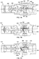
- Figures 7A to 7C show the gate valve apparatus 210 in sequential stages of closing, from fully open in Figure 7A , partially closed (and cutting) in Figure 7B , and fully closed and sealed in Figure 7A .
- the gate valve apparatus 210 includes a housing 212 defining a flow path 214, with a valve seat 218 mounted around the periphery of the flow path 214.
- the valve seat 218 is identical in form and function to the first valve seat 18 of the gate valve apparatus 10 described above, and thus includes a cutting edge, referred to as a second cutting edge 228, and a first peripheral seal surface 230. No further detailed description will be given for purposes of brevity.
- the gate valve apparatus 210 further includes a gate valve member 234 arranged for lateral movement across the flow path, by operation of a piston member 282 connected via a valve stem 280.
- the gate valve member 234 includes a first cutting edge 240, and a seal pocket 242, wherein the seal pocket 242 is identical in form and function to the first seal pocket 42 of apparatus 10 and as such no further detailed description will be given, except to confirm that the seal pocket 242 includes a recessed second peripheral seal surface 244.
- FIGs 8A and 8B show enlarged views of the gate valve member 234 in its fully closed position.
- the valve seat 218 is shown urged into the seal pocket 242 of the gate valve member 116 by spring 224. Further, pressure applied from above will press the valve seat 218 downwardly against the valve member 234.
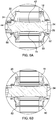
- FIGS 9 to 12 illustrate a further example of a gate valve apparatus 410.
- Gate valve apparatus 410 is similar in many respects to gate valve apparatus 10, and as such like features share like reference numerals, incremented by 400.
- Figure 9 provides a sectional view of the gate valve apparatus 410, while Figure 10 provides a partially sectional perspective view.
- the gate valve apparatus 410 includes a housing 412 which defines a flow path 414 which extends along a longitudinal axis 416.
- a first valve seat 418 is located within the housing 412 around a periphery of the flow path 414.
- the first valve seat 418 is provided as a separate insert which is rigidly mounted and sealed within a receptive pocket 420 of the housing.
- the first valve seat 418 includes a cutting insert 426 which defines a peripheral cutter or cutting edge 428.
- the cutting edge 428 will be referred to as a third cutting edge 428.
- the first valve seat 418 further includes a first peripheral seal surface 430 which tapers upwardly and outwardly from the cutting insert 426.
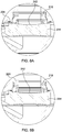
- the apparatus 410 comprises a gate valve assembly 434 which is moveable laterally across the flow path 414, generally along a lateral axis 436, from an open position, as illustrated in Figures 9 and 10 , to a closed position, as illustrated in Figure 11 .
- valve member assembly 434 When the valve member assembly 434 is fully closed, as illustrated in Figure 11 , the first valve seat 418 is received within the first seal pocket 442 of the first valve member 434b, by virtue of the first valve member 434b being moveable relative to the valve carriage 434a. Similarly, the second valve seat 450 is received within the second seal pocket 474 of the second valve member 434c, by virtue of the second valve member 434c being moveable relative to the valve carriage 434a.
- the valve apparatus may thus facilitate sealing along the flow path 414 in reverse directions.
- valve members 434b, 434c are provided within the gate valve apparatus 410 .
- a single valve member may be provided to perform the same function.
- Such an arrangement is illustrated in Figure 12 , with the single valve member identified with reference numeral 120.
- the single valve member 120 is moveable axially relative to the valve carriage 434a, and carries or includes both the first and second seal pockets 442, 474.
- a further modification in the arrangement of Figure 12 allows the first and second valve seats 418, 450 to move within the housing 412, biased by respective washer springs 424, 456.
Landscapes
- Engineering & Computer Science (AREA)
- Geology (AREA)
- Life Sciences & Earth Sciences (AREA)
- Mining & Mineral Resources (AREA)
- Environmental & Geological Engineering (AREA)
- Fluid Mechanics (AREA)
- Physics & Mathematics (AREA)
- General Life Sciences & Earth Sciences (AREA)
- Geochemistry & Mineralogy (AREA)
- General Engineering & Computer Science (AREA)
- Mechanical Engineering (AREA)
- Sliding Valves (AREA)
- Details Of Valves (AREA)
Claims (15)
- Absperrschiebervorrichtung, die Folgendes umfasst:ein Gehäuse (12), das eine Strömungsbahn (14) definiert,einen ersten Ventilsitz (18), der innerhalb des Gehäuses (12) um einen Umfang der Strömungsbahn (14) herum angeordnet ist und eine erste umlaufende Dichtungsfläche (30) umfasst, undein Absperrschieberelement (34), das in Seitenrichtung über die Strömungsbahn (14) beweglich ist, zwischen einer ersten Stellung, in der die Strömungsbahn (14) offen ist, und einer zweiten Stellung, in der die Strömungsbahn (14) geschlossen ist,eine erste Schneidvorrichtung (38), die so an einem Kantenbereich einer ersten Fläche des Absperrschieberelements (34) bereitgestellt ist, dass sie mit dem Absperrschieberelement (34) entlang einer ersten Schneidebene (33) über die Strömungsbahn (14) beweglich ist, undeine erste Dichtungstasche (42), die durch eine Vertiefung in der ersten Fläche des Absperrschieberelements (34) gebildet wird, wobei eine zweite umlaufende Dichtungsfläche (44) innerhalb der ersten Dichtungstasche (42) bereitgestellt wird,wobei der erste Ventilsitz (18) und das Absperrschieberelement (34) in Axialrichtung im Verhältnis zueinander beweglich sind, um zu ermöglichen, dass ein Abschnitt des ersten Ventilsitzes (18) in die erste Dichtungstasche (42) des Absperrschieberelements (34) aufgenommen wird, wenn sich das Absperrschieberelement (34) innerhalb seiner zweiten Stellung befindet, um einen abdichtenden Eingriff zwischen der ersten und der zweiten umlaufenden Dichtungsfläche (30, 44) zu gewährleisten.
- Absperrschiebervorrichtung nach Anspruch 1, wobei die erste Fläche des Absperrschieberelements (34) während einer seitlichen Bewegung des Absperrschieberelements (34) den ersten Ventilsitz (18) verschiebbar in Eingriff nimmt und wahlweise
wobei ein gleitender Eingriff zwischen dem ersten Ventilsitz (18) und der ersten Fläche des Absperrschieberelements (34) die erste Schneidkante (38) während einer seitlichen Bewegung des Absperrschieberelements (34) mit der ersten Schneidebene (33) ausgerichtet hält. - Absperrschiebervorrichtung nach einem der vorhergehenden Ansprüche, wobei die Geometrie der ersten Dichtungstasche (42) die Geometrie des ersten Ventilsitzes (18) ergänzt, um zu ermöglichen, dass der erste Ventilsitz (18) nur innerhalb der ersten Dichtungstasche (42) aufgenommen wird, wenn sich das Absperrschieberelement in seiner geschlossenen Stellung befindet.
- Absperrschiebervorrichtung nach einem der vorhergehenden Ansprüche, wobei das Absperrschieberelement (34) und der erste Ventilsitz (18) in Axialrichtung im Verhältnis zueinander in einer ersten relativen Richtung beweglich sind, um zu ermöglichen, dass der erste Ventilsitz (18) innerhalb der ersten Dichtungstasche (42) aufgenommen wird, wenn sich das Absperrschieberelement (34) in seiner geschlossenen Stellung befindet, und in Axialrichtung im Verhältnis zueinander in einer entgegengesetzten zweiten relativen Richtung beweglich sind, um zu ermöglichen, dass der erste Ventilsitz (18) aus der ersten Dichtungstasche (42) entfernt wird, wenn das Absperrschieberelement (34) von seiner geschlossenen Stellung hin zu seiner offenen Stellung bewegt wird.
- Absperrschiebervorrichtung nach einem der vorhergehenden Ansprüche, wobei die erste Dichtungstasche (42) im Allgemeinen kreisförmig ist und die zweite umlaufende Dichtungsfläche (44) im Allgemeinen ringförmig ist.
- Absperrschiebervorrichtung nach einem der vorhergehenden Ansprüche, wobei die erste Dichtungstasche (42) einen mittigen Bereich (46) umfasst, der eine Basis der ersten Dichtungstasche (42) definiert, und die zweite umlaufende Dichtungsfläche (44) den mittigen Bereich (46) der Dichtungstasche (42) umschließt, und wahlweise
wobei der mittige Bereich (46) der ersten Dichtungstasche (42) mit der Strömungsbahn (14) des Gehäuses (12) ausgerichtet ist, wenn sich das Absperrschieberelement (34) in seiner geschlossenen Stellung befindet, so dass der mittige Bereich (46) einen Aufprallbereich für jegliches Objekt definiert, das sich innerhalb der Strömungsbahn (14) bewegt. - Absperrschiebervorrichtung nach einem der vorhergehenden Ansprüche, wobei der erste Ventilsitz (18) eine zweite Schneidkante (28) umfasst, die dafür konfiguriert ist, mit der ersten Schneidkante (38) des Absperrschieberelements (34) zusammenzuwirken, um ein Objekt, das sich zwischen denselben befindet, auszuschneiden, und wahlweise
wobei die zweite Schneidkante (28) einen inneren Umfang des ersten Ventilsitzes (18) definiert und die erste umlaufende Dichtungsfläche (30) in Radialrichtung außerhalb der zweiten Schneidkante (28) angeordnet ist. - Absperrschiebervorrichtung nach Anspruch 7, wobei die erste umlaufende Dichtungsfläche (30) im Verhältnis zu der zweiten Schneidkante (28) ausgespart ist.
- Absperrschiebervorrichtung nach Anspruch 7 oder 8, wobei die zweite Schneidkante (28) während einer seitlichen Bewegung des Absperrschieberelements (34) an der ersten Fläche des Absperrschieberelements (34) anliegt.
- Absperrschiebervorrichtung nach einem der vorhergehenden Ansprüche, wobei eine relative axiale Bewegung zwischen dem ersten Ventilsitz (18) und dem Absperrschieberelement (34) erleichtert, dass eine Abdichtung in einer oder beiden Richtungen über das Absperrschieberelement (34) erreicht wird, wenn es geschlossen ist, und/oder
wobei der erste Ventilsitz (18) in Axialrichtung im Verhältnis zu dem Gehäuse (12) beweglich ist und wahlweise
wobei der erste Ventilsitz (18) hin zu einem Eingriff mit dem Absperrschieberelement (34) vorgespannt wird. - Absperrschiebervorrichtung nach einem der vorhergehenden Ansprüche, wobei sowohl der erste Ventilsitz (18) als auch das Absperrschieberelement (34) in Axialrichtung innerhalb des Gehäuses (12) beweglich sind, um eine relative axiale Bewegung zwischen denselben zu ermöglichen.
- Absperrschiebervorrichtung nach einem der vorhergehenden Ansprüche, die Folgendes umfasst:einen zweiten Ventilsitz (50), der innerhalb des Gehäuses (12) auf einer von dem ersten Ventilsitz (18) entgegengesetzten Seite des Absperrschieberelements (34) angeordnet ist, wobei der zweite Ventilsitz (50) eine dritte umlaufende Dichtungsfläche (62) umfasst,eine dritte Schneidkante (72), die an einem Kantenbereich einer zweiten Fläche des Absperrschieberelements (34) bereitgestellt ist und mit dem Absperrschieberelement (34) über die Strömungsbahn (14) beweglich ist,eine zweite Dichtungstasche (74), die durch eine Vertiefung in der zweiten Fläche des Absperrschieberelements (34) definiert wird, wobei eine vierte umlaufende Dichtungsfläche (76) innerhalb der zweiten Dichtungstasche (74) bereitgestellt wird,wobei der zweite Ventilsitz (50) und das Absperrschieberelement (34) in Axialrichtung im Verhältnis zueinander verschiebbar sind, um zu ermöglichen, dass ein Abschnitt des zweiten Ventilsitzes (50) in die zweite Dichtungstasche (74) des Absperrschieberelements (34) aufgenommen wird, wenn sich das Absperrschieberelement (34) innerhalb seiner zweiten Stellung befindet, um einen abdichtenden Eingriff zwischen der dritten und der vierten umlaufenden Dichtungsfläche (62, 76) zu gewährleisten.
- Absperrschiebervorrichtung nach Anspruch 12, wobei der zweite Ventilsitz (50) eine vierte Schneidkante (60) umfasst, die mit der dritten Schneidkante (72) zusammenwirkt, um ein Objekt, das sich zwischen denselben befindet, auszuschneiden.
- Absperrschiebervorrichtung nach einem der vorhergehenden Ansprüche, die einen Ventilschaft (80) umfasst, der mit dem Absperrschieberelement (34) verbunden ist, um eine seitliche Bewegung des Absperrschieberelements (34) zu erleichtern, wobei der Ventilschaft (80) dafür konfiguriert ist, mit einem Stellantrieb verbunden zu werden, und wahlweise
wobei das Absperrschieberelement (34) und der Ventilschaft (80) über einen Schaftverbinder (84) miteinander verbunden sind, wobei der Schaftverbinder (84) ermöglicht, dass sich das Absperrschieberelement (34) in Axialrichtung innerhalb des Gehäuses (12) ohne eine entsprechende axiale Bewegung des Ventilschafts (80) bewegt. - Verfahren zum Bereitstellen einer Fluidregelung entlang einer Strömungsbahn, welches das Betreiben einer Absperrschiebervorrichtung nach einem der vorhergehenden Ansprüche umfasst.
Applications Claiming Priority (2)
| Application Number | Priority Date | Filing Date | Title |
|---|---|---|---|
| GBGB1619693.3A GB201619693D0 (en) | 2016-11-22 | 2016-11-22 | Gate valve |
| PCT/GB2017/053348 WO2018096312A1 (en) | 2016-11-22 | 2017-11-07 | Gate valve |
Publications (2)
| Publication Number | Publication Date |
|---|---|
| EP3545166A1 EP3545166A1 (de) | 2019-10-02 |
| EP3545166B1 true EP3545166B1 (de) | 2020-12-23 |
Family
ID=57993775
Family Applications (1)
| Application Number | Title | Priority Date | Filing Date |
|---|---|---|---|
| EP17798273.3A Active EP3545166B1 (de) | 2016-11-22 | 2017-11-07 | Absperrventil |
Country Status (5)
| Country | Link |
|---|---|
| US (1) | US10801287B2 (de) |
| EP (1) | EP3545166B1 (de) |
| AU (1) | AU2017364303B2 (de) |
| GB (1) | GB201619693D0 (de) |
| WO (1) | WO2018096312A1 (de) |
Families Citing this family (5)
| Publication number | Priority date | Publication date | Assignee | Title |
|---|---|---|---|---|
| WO2017119894A1 (en) * | 2016-01-07 | 2017-07-13 | National Oilwell Varco, L.P. | Blowout preventer with interlocking ram assembly and method of using same |
| NO345339B1 (en) | 2018-10-05 | 2020-12-14 | Aker Solutions As | Gate valve assembly for a subsea workover system |
| US11174958B2 (en) | 2019-01-24 | 2021-11-16 | Jet Oilfield Services, LLC | Gate valve and method of repairing same |
| EP3963176A4 (de) | 2019-04-30 | 2023-05-10 | RCE Corporation | Vorrichtung und verfahren für ein gasliftventil |
| CN111570692B (zh) * | 2020-05-19 | 2023-01-24 | 强大阀门集团有限公司 | 大直径整体锻造闸阀的成形工艺 |
Family Cites Families (10)
| Publication number | Priority date | Publication date | Assignee | Title |
|---|---|---|---|---|
| US2029151A (en) * | 1934-10-18 | 1936-01-28 | Freyn Engineering Co | Goggle valve |
| US2908480A (en) * | 1955-01-31 | 1959-10-13 | Chiksan Co | Pressure relieved valve seal |
| US3446476A (en) * | 1965-05-12 | 1969-05-27 | Balon Corp | Valves with movable seals |
| US3463447A (en) * | 1968-05-27 | 1969-08-26 | Grove Valve & Regulator Co | Valve structure with protected resilient seals |
| US4671312A (en) * | 1984-05-14 | 1987-06-09 | Axelson, Inc. | Wireline cutting actuator and valve |
| AT388423B (de) * | 1986-02-14 | 1989-06-26 | Boehm Walter | Absperrschieber fuer rohrleitungen |
| US4911410A (en) * | 1989-07-21 | 1990-03-27 | Cameron Iron Works Usa, Inc. | Shearing gate valve |
| US5501424A (en) * | 1994-02-09 | 1996-03-26 | Fmc Corporation | Wire cutting insert for gate valve |
| US5803431A (en) * | 1995-08-31 | 1998-09-08 | Cooper Cameron Corporation | Shearing gate valve |
| US6688324B2 (en) * | 2002-01-08 | 2004-02-10 | Cooper Cameron Corporation | Valve for hydrate forming environments |
-
2016
- 2016-11-22 GB GBGB1619693.3A patent/GB201619693D0/en not_active Ceased
-
2017
- 2017-11-07 EP EP17798273.3A patent/EP3545166B1/de active Active
- 2017-11-07 US US16/333,863 patent/US10801287B2/en active Active
- 2017-11-07 AU AU2017364303A patent/AU2017364303B2/en active Active
- 2017-11-07 WO PCT/GB2017/053348 patent/WO2018096312A1/en not_active Ceased
Non-Patent Citations (1)
| Title |
|---|
| None * |
Also Published As
| Publication number | Publication date |
|---|---|
| EP3545166A1 (de) | 2019-10-02 |
| US20190277106A1 (en) | 2019-09-12 |
| AU2017364303B2 (en) | 2022-10-27 |
| WO2018096312A1 (en) | 2018-05-31 |
| BR112019006704A2 (pt) | 2019-06-25 |
| AU2017364303A1 (en) | 2019-04-18 |
| CA3038457A1 (en) | 2018-05-31 |
| US10801287B2 (en) | 2020-10-13 |
| GB201619693D0 (en) | 2017-01-04 |
Similar Documents
| Publication | Publication Date | Title |
|---|---|---|
| EP3545166B1 (de) | Absperrventil | |
| US12385349B2 (en) | Blowout preventer with multiple application ram blades | |
| EP3959415B1 (de) | Scherbacke für ausbruchschieber | |
| EP3187681B1 (de) | Schneidsequenz für eine preventergarnitur | |
| US20160102518A1 (en) | Shear Ram Blowout Preventer with Engagement Feature | |
| US20170370180A1 (en) | Ball valve | |
| US11286740B2 (en) | Blowout preventer shearing ram | |
| AU2016269054B2 (en) | Wellbore control device | |
| US9194202B2 (en) | Fishing tool for drill pipe | |
| US20160298409A1 (en) | High-Strength Blowout Preventer Shearing Ram and Connecting Rod | |
| US9976373B2 (en) | Blowout preventer with shear ram | |
| US10202817B2 (en) | Packer assembly with inserts for blowout preventer | |
| CN107002477B (zh) | 用于在紧急情况下的提取井的阀组件和控制方法 | |
| EP2971466B1 (de) | Absperrventilanordnung mit einem tragkörper | |
| CA3038457C (en) | Gate valve | |
| EP3161243B1 (de) | Ventilvorrichtung | |
| US11118419B2 (en) | Wellbore control device | |
| EP2971465B1 (de) | Absperrventilanordnung mit einer dichtungsanordnung | |
| BR112019006704B1 (pt) | Aparelho de válvula gaveta, e, método para prover controle de fluido | |
| GB2562992A (en) | Closure apparatus |
Legal Events
| Date | Code | Title | Description |
|---|---|---|---|
| STAA | Information on the status of an ep patent application or granted ep patent |
Free format text: STATUS: UNKNOWN |
|
| STAA | Information on the status of an ep patent application or granted ep patent |
Free format text: STATUS: THE INTERNATIONAL PUBLICATION HAS BEEN MADE |
|
| PUAI | Public reference made under article 153(3) epc to a published international application that has entered the european phase |
Free format text: ORIGINAL CODE: 0009012 |
|
| STAA | Information on the status of an ep patent application or granted ep patent |
Free format text: STATUS: REQUEST FOR EXAMINATION WAS MADE |
|
| 17P | Request for examination filed |
Effective date: 20190308 |
|
| AK | Designated contracting states |
Kind code of ref document: A1 Designated state(s): AL AT BE BG CH CY CZ DE DK EE ES FI FR GB GR HR HU IE IS IT LI LT LU LV MC MK MT NL NO PL PT RO RS SE SI SK SM TR |
|
| AX | Request for extension of the european patent |
Extension state: BA ME |
|
| DAV | Request for validation of the european patent (deleted) | ||
| DAX | Request for extension of the european patent (deleted) | ||
| GRAP | Despatch of communication of intention to grant a patent |
Free format text: ORIGINAL CODE: EPIDOSNIGR1 |
|
| STAA | Information on the status of an ep patent application or granted ep patent |
Free format text: STATUS: GRANT OF PATENT IS INTENDED |
|
| INTG | Intention to grant announced |
Effective date: 20200923 |
|
| GRAS | Grant fee paid |
Free format text: ORIGINAL CODE: EPIDOSNIGR3 |
|
| GRAA | (expected) grant |
Free format text: ORIGINAL CODE: 0009210 |
|
| STAA | Information on the status of an ep patent application or granted ep patent |
Free format text: STATUS: THE PATENT HAS BEEN GRANTED |
|
| AK | Designated contracting states |
Kind code of ref document: B1 Designated state(s): AL AT BE BG CH CY CZ DE DK EE ES FI FR GB GR HR HU IE IS IT LI LT LU LV MC MK MT NL NO PL PT RO RS SE SI SK SM TR |
|
| REG | Reference to a national code |
Ref country code: GB Ref legal event code: FG4D |
|
| REG | Reference to a national code |
Ref country code: DE Ref legal event code: R096 Ref document number: 602017030161 Country of ref document: DE |
|
| REG | Reference to a national code |
Ref country code: AT Ref legal event code: REF Ref document number: 1347892 Country of ref document: AT Kind code of ref document: T Effective date: 20210115 |
|
| REG | Reference to a national code |
Ref country code: IE Ref legal event code: FG4D |
|
| PG25 | Lapsed in a contracting state [announced via postgrant information from national office to epo] |
Ref country code: GR Free format text: LAPSE BECAUSE OF FAILURE TO SUBMIT A TRANSLATION OF THE DESCRIPTION OR TO PAY THE FEE WITHIN THE PRESCRIBED TIME-LIMIT Effective date: 20210324 Ref country code: FI Free format text: LAPSE BECAUSE OF FAILURE TO SUBMIT A TRANSLATION OF THE DESCRIPTION OR TO PAY THE FEE WITHIN THE PRESCRIBED TIME-LIMIT Effective date: 20201223 Ref country code: RS Free format text: LAPSE BECAUSE OF FAILURE TO SUBMIT A TRANSLATION OF THE DESCRIPTION OR TO PAY THE FEE WITHIN THE PRESCRIBED TIME-LIMIT Effective date: 20201223 |
|
| REG | Reference to a national code |
Ref country code: AT Ref legal event code: MK05 Ref document number: 1347892 Country of ref document: AT Kind code of ref document: T Effective date: 20201223 |
|
| REG | Reference to a national code |
Ref country code: NL Ref legal event code: MP Effective date: 20201223 |
|
| PG25 | Lapsed in a contracting state [announced via postgrant information from national office to epo] |
Ref country code: LV Free format text: LAPSE BECAUSE OF FAILURE TO SUBMIT A TRANSLATION OF THE DESCRIPTION OR TO PAY THE FEE WITHIN THE PRESCRIBED TIME-LIMIT Effective date: 20201223 Ref country code: SE Free format text: LAPSE BECAUSE OF FAILURE TO SUBMIT A TRANSLATION OF THE DESCRIPTION OR TO PAY THE FEE WITHIN THE PRESCRIBED TIME-LIMIT Effective date: 20201223 Ref country code: BG Free format text: LAPSE BECAUSE OF FAILURE TO SUBMIT A TRANSLATION OF THE DESCRIPTION OR TO PAY THE FEE WITHIN THE PRESCRIBED TIME-LIMIT Effective date: 20210323 |
|
| REG | Reference to a national code |
Ref country code: NO Ref legal event code: T2 Effective date: 20201223 |
|
| PG25 | Lapsed in a contracting state [announced via postgrant information from national office to epo] |
Ref country code: HR Free format text: LAPSE BECAUSE OF FAILURE TO SUBMIT A TRANSLATION OF THE DESCRIPTION OR TO PAY THE FEE WITHIN THE PRESCRIBED TIME-LIMIT Effective date: 20201223 Ref country code: NL Free format text: LAPSE BECAUSE OF FAILURE TO SUBMIT A TRANSLATION OF THE DESCRIPTION OR TO PAY THE FEE WITHIN THE PRESCRIBED TIME-LIMIT Effective date: 20201223 |
|
| REG | Reference to a national code |
Ref country code: LT Ref legal event code: MG9D |
|
| PG25 | Lapsed in a contracting state [announced via postgrant information from national office to epo] |
Ref country code: LT Free format text: LAPSE BECAUSE OF FAILURE TO SUBMIT A TRANSLATION OF THE DESCRIPTION OR TO PAY THE FEE WITHIN THE PRESCRIBED TIME-LIMIT Effective date: 20201223 Ref country code: CZ Free format text: LAPSE BECAUSE OF FAILURE TO SUBMIT A TRANSLATION OF THE DESCRIPTION OR TO PAY THE FEE WITHIN THE PRESCRIBED TIME-LIMIT Effective date: 20201223 Ref country code: EE Free format text: LAPSE BECAUSE OF FAILURE TO SUBMIT A TRANSLATION OF THE DESCRIPTION OR TO PAY THE FEE WITHIN THE PRESCRIBED TIME-LIMIT Effective date: 20201223 Ref country code: SM Free format text: LAPSE BECAUSE OF FAILURE TO SUBMIT A TRANSLATION OF THE DESCRIPTION OR TO PAY THE FEE WITHIN THE PRESCRIBED TIME-LIMIT Effective date: 20201223 Ref country code: PT Free format text: LAPSE BECAUSE OF FAILURE TO SUBMIT A TRANSLATION OF THE DESCRIPTION OR TO PAY THE FEE WITHIN THE PRESCRIBED TIME-LIMIT Effective date: 20210423 Ref country code: RO Free format text: LAPSE BECAUSE OF FAILURE TO SUBMIT A TRANSLATION OF THE DESCRIPTION OR TO PAY THE FEE WITHIN THE PRESCRIBED TIME-LIMIT Effective date: 20201223 Ref country code: SK Free format text: LAPSE BECAUSE OF FAILURE TO SUBMIT A TRANSLATION OF THE DESCRIPTION OR TO PAY THE FEE WITHIN THE PRESCRIBED TIME-LIMIT Effective date: 20201223 |
|
| PG25 | Lapsed in a contracting state [announced via postgrant information from national office to epo] |
Ref country code: AT Free format text: LAPSE BECAUSE OF FAILURE TO SUBMIT A TRANSLATION OF THE DESCRIPTION OR TO PAY THE FEE WITHIN THE PRESCRIBED TIME-LIMIT Effective date: 20201223 Ref country code: PL Free format text: LAPSE BECAUSE OF FAILURE TO SUBMIT A TRANSLATION OF THE DESCRIPTION OR TO PAY THE FEE WITHIN THE PRESCRIBED TIME-LIMIT Effective date: 20201223 |
|
| REG | Reference to a national code |
Ref country code: DE Ref legal event code: R097 Ref document number: 602017030161 Country of ref document: DE |
|
| PG25 | Lapsed in a contracting state [announced via postgrant information from national office to epo] |
Ref country code: IS Free format text: LAPSE BECAUSE OF FAILURE TO SUBMIT A TRANSLATION OF THE DESCRIPTION OR TO PAY THE FEE WITHIN THE PRESCRIBED TIME-LIMIT Effective date: 20210423 |
|
| PG25 | Lapsed in a contracting state [announced via postgrant information from national office to epo] |
Ref country code: AL Free format text: LAPSE BECAUSE OF FAILURE TO SUBMIT A TRANSLATION OF THE DESCRIPTION OR TO PAY THE FEE WITHIN THE PRESCRIBED TIME-LIMIT Effective date: 20201223 Ref country code: IT Free format text: LAPSE BECAUSE OF FAILURE TO SUBMIT A TRANSLATION OF THE DESCRIPTION OR TO PAY THE FEE WITHIN THE PRESCRIBED TIME-LIMIT Effective date: 20201223 |
|
| PLBE | No opposition filed within time limit |
Free format text: ORIGINAL CODE: 0009261 |
|
| STAA | Information on the status of an ep patent application or granted ep patent |
Free format text: STATUS: NO OPPOSITION FILED WITHIN TIME LIMIT |
|
| PG25 | Lapsed in a contracting state [announced via postgrant information from national office to epo] |
Ref country code: DK Free format text: LAPSE BECAUSE OF FAILURE TO SUBMIT A TRANSLATION OF THE DESCRIPTION OR TO PAY THE FEE WITHIN THE PRESCRIBED TIME-LIMIT Effective date: 20201223 |
|
| 26N | No opposition filed |
Effective date: 20210924 |
|
| PG25 | Lapsed in a contracting state [announced via postgrant information from national office to epo] |
Ref country code: ES Free format text: LAPSE BECAUSE OF FAILURE TO SUBMIT A TRANSLATION OF THE DESCRIPTION OR TO PAY THE FEE WITHIN THE PRESCRIBED TIME-LIMIT Effective date: 20201223 |
|
| PG25 | Lapsed in a contracting state [announced via postgrant information from national office to epo] |
Ref country code: SI Free format text: LAPSE BECAUSE OF FAILURE TO SUBMIT A TRANSLATION OF THE DESCRIPTION OR TO PAY THE FEE WITHIN THE PRESCRIBED TIME-LIMIT Effective date: 20201223 |
|
| PG25 | Lapsed in a contracting state [announced via postgrant information from national office to epo] |
Ref country code: IS Free format text: LAPSE BECAUSE OF FAILURE TO SUBMIT A TRANSLATION OF THE DESCRIPTION OR TO PAY THE FEE WITHIN THE PRESCRIBED TIME-LIMIT Effective date: 20210423 |
|
| REG | Reference to a national code |
Ref country code: DE Ref legal event code: R119 Ref document number: 602017030161 Country of ref document: DE |
|
| PG25 | Lapsed in a contracting state [announced via postgrant information from national office to epo] |
Ref country code: MC Free format text: LAPSE BECAUSE OF FAILURE TO SUBMIT A TRANSLATION OF THE DESCRIPTION OR TO PAY THE FEE WITHIN THE PRESCRIBED TIME-LIMIT Effective date: 20201223 |
|
| REG | Reference to a national code |
Ref country code: CH Ref legal event code: PL |
|
| PG25 | Lapsed in a contracting state [announced via postgrant information from national office to epo] |
Ref country code: LU Free format text: LAPSE BECAUSE OF NON-PAYMENT OF DUE FEES Effective date: 20211107 Ref country code: BE Free format text: LAPSE BECAUSE OF NON-PAYMENT OF DUE FEES Effective date: 20211130 |
|
| REG | Reference to a national code |
Ref country code: BE Ref legal event code: MM Effective date: 20211130 |
|
| PG25 | Lapsed in a contracting state [announced via postgrant information from national office to epo] |
Ref country code: IE Free format text: LAPSE BECAUSE OF NON-PAYMENT OF DUE FEES Effective date: 20211107 Ref country code: DE Free format text: LAPSE BECAUSE OF NON-PAYMENT OF DUE FEES Effective date: 20220601 |
|
| PG25 | Lapsed in a contracting state [announced via postgrant information from national office to epo] |
Ref country code: CY Free format text: LAPSE BECAUSE OF FAILURE TO SUBMIT A TRANSLATION OF THE DESCRIPTION OR TO PAY THE FEE WITHIN THE PRESCRIBED TIME-LIMIT Effective date: 20201223 |
|
| PG25 | Lapsed in a contracting state [announced via postgrant information from national office to epo] |
Ref country code: LI Free format text: LAPSE BECAUSE OF NON-PAYMENT OF DUE FEES Effective date: 20220701 Ref country code: HU Free format text: LAPSE BECAUSE OF FAILURE TO SUBMIT A TRANSLATION OF THE DESCRIPTION OR TO PAY THE FEE WITHIN THE PRESCRIBED TIME-LIMIT; INVALID AB INITIO Effective date: 20171107 Ref country code: CH Free format text: LAPSE BECAUSE OF NON-PAYMENT OF DUE FEES Effective date: 20220701 |
|
| PG25 | Lapsed in a contracting state [announced via postgrant information from national office to epo] |
Ref country code: MK Free format text: LAPSE BECAUSE OF FAILURE TO SUBMIT A TRANSLATION OF THE DESCRIPTION OR TO PAY THE FEE WITHIN THE PRESCRIBED TIME-LIMIT Effective date: 20201223 |
|
| PG25 | Lapsed in a contracting state [announced via postgrant information from national office to epo] |
Ref country code: MT Free format text: LAPSE BECAUSE OF FAILURE TO SUBMIT A TRANSLATION OF THE DESCRIPTION OR TO PAY THE FEE WITHIN THE PRESCRIBED TIME-LIMIT Effective date: 20201223 |
|
| PGFP | Annual fee paid to national office [announced via postgrant information from national office to epo] |
Ref country code: GB Payment date: 20250918 Year of fee payment: 9 |
|
| PGFP | Annual fee paid to national office [announced via postgrant information from national office to epo] |
Ref country code: FR Payment date: 20250908 Year of fee payment: 9 |
|
| PG25 | Lapsed in a contracting state [announced via postgrant information from national office to epo] |
Ref country code: TR Free format text: LAPSE BECAUSE OF FAILURE TO SUBMIT A TRANSLATION OF THE DESCRIPTION OR TO PAY THE FEE WITHIN THE PRESCRIBED TIME-LIMIT Effective date: 20201223 |
|
| PGFP | Annual fee paid to national office [announced via postgrant information from national office to epo] |
Ref country code: NO Payment date: 20251113 Year of fee payment: 9 |