EP3545144B1 - Node elements, kits, and methods - Google Patents
Node elements, kits, and methods Download PDFInfo
- Publication number
- EP3545144B1 EP3545144B1 EP17801723.2A EP17801723A EP3545144B1 EP 3545144 B1 EP3545144 B1 EP 3545144B1 EP 17801723 A EP17801723 A EP 17801723A EP 3545144 B1 EP3545144 B1 EP 3545144B1
- Authority
- EP
- European Patent Office
- Prior art keywords
- node element
- node
- bar
- bars
- coupling side
- Prior art date
- Legal status (The legal status is an assumption and is not a legal conclusion. Google has not performed a legal analysis and makes no representation as to the accuracy of the status listed.)
- Active
Links
- 238000000034 method Methods 0.000 title claims description 18
- 230000014759 maintenance of location Effects 0.000 claims description 67
- 230000008878 coupling Effects 0.000 claims description 57
- 238000010168 coupling process Methods 0.000 claims description 57
- 238000005859 coupling reaction Methods 0.000 claims description 57
- 238000003780 insertion Methods 0.000 claims description 22
- 230000037431 insertion Effects 0.000 claims description 22
- 239000000463 material Substances 0.000 description 16
- 238000003466 welding Methods 0.000 description 11
- 230000033001 locomotion Effects 0.000 description 9
- 239000002184 metal Substances 0.000 description 4
- 229910052751 metal Inorganic materials 0.000 description 4
- 238000009434 installation Methods 0.000 description 3
- 239000004033 plastic Substances 0.000 description 3
- 229920003023 plastic Polymers 0.000 description 3
- 229920002430 Fibre-reinforced plastic Polymers 0.000 description 2
- 239000004918 carbon fiber reinforced polymer Substances 0.000 description 2
- 239000011151 fibre-reinforced plastic Substances 0.000 description 2
- 238000004519 manufacturing process Methods 0.000 description 2
- 230000013011 mating Effects 0.000 description 2
- ORQBXQOJMQIAOY-UHFFFAOYSA-N nobelium Chemical compound [No] ORQBXQOJMQIAOY-UHFFFAOYSA-N 0.000 description 2
- 239000007787 solid Substances 0.000 description 2
- OKTJSMMVPCPJKN-UHFFFAOYSA-N Carbon Chemical compound [C] OKTJSMMVPCPJKN-UHFFFAOYSA-N 0.000 description 1
- 229910000831 Steel Inorganic materials 0.000 description 1
- RTAQQCXQSZGOHL-UHFFFAOYSA-N Titanium Chemical compound [Ti] RTAQQCXQSZGOHL-UHFFFAOYSA-N 0.000 description 1
- 229910052782 aluminium Inorganic materials 0.000 description 1
- XAGFODPZIPBFFR-UHFFFAOYSA-N aluminium Chemical compound [Al] XAGFODPZIPBFFR-UHFFFAOYSA-N 0.000 description 1
- 238000005452 bending Methods 0.000 description 1
- 230000005540 biological transmission Effects 0.000 description 1
- 229910052799 carbon Inorganic materials 0.000 description 1
- 230000001010 compromised effect Effects 0.000 description 1
- 239000004567 concrete Substances 0.000 description 1
- 230000007423 decrease Effects 0.000 description 1
- 230000002349 favourable effect Effects 0.000 description 1
- 239000011210 fiber-reinforced concrete Substances 0.000 description 1
- 239000011152 fibreglass Substances 0.000 description 1
- 239000007770 graphite material Substances 0.000 description 1
- 238000001746 injection moulding Methods 0.000 description 1
- 238000005058 metal casting Methods 0.000 description 1
- 238000003801 milling Methods 0.000 description 1
- 238000012986 modification Methods 0.000 description 1
- 230000004048 modification Effects 0.000 description 1
- 238000002360 preparation method Methods 0.000 description 1
- 239000000243 solution Substances 0.000 description 1
- 239000010959 steel Substances 0.000 description 1
- 239000010936 titanium Substances 0.000 description 1
- 229910052719 titanium Inorganic materials 0.000 description 1
Images


Classifications
-
- E—FIXED CONSTRUCTIONS
- E04—BUILDING
- E04B—GENERAL BUILDING CONSTRUCTIONS; WALLS, e.g. PARTITIONS; ROOFS; FLOORS; CEILINGS; INSULATION OR OTHER PROTECTION OF BUILDINGS
- E04B1/00—Constructions in general; Structures which are not restricted either to walls, e.g. partitions, or floors or ceilings or roofs
- E04B1/18—Structures comprising elongated load-supporting parts, e.g. columns, girders, skeletons
- E04B1/19—Three-dimensional framework structures
- E04B1/1903—Connecting nodes specially adapted therefor
-
- F—MECHANICAL ENGINEERING; LIGHTING; HEATING; WEAPONS; BLASTING
- F16—ENGINEERING ELEMENTS AND UNITS; GENERAL MEASURES FOR PRODUCING AND MAINTAINING EFFECTIVE FUNCTIONING OF MACHINES OR INSTALLATIONS; THERMAL INSULATION IN GENERAL
- F16B—DEVICES FOR FASTENING OR SECURING CONSTRUCTIONAL ELEMENTS OR MACHINE PARTS TOGETHER, e.g. NAILS, BOLTS, CIRCLIPS, CLAMPS, CLIPS OR WEDGES; JOINTS OR JOINTING
- F16B9/00—Connections of rods or tubular parts to flat surfaces at an angle
- F16B9/05—Connections of rods or tubular parts to flat surfaces at an angle by way of an intermediate member
-
- E—FIXED CONSTRUCTIONS
- E04—BUILDING
- E04B—GENERAL BUILDING CONSTRUCTIONS; WALLS, e.g. PARTITIONS; ROOFS; FLOORS; CEILINGS; INSULATION OR OTHER PROTECTION OF BUILDINGS
- E04B1/00—Constructions in general; Structures which are not restricted either to walls, e.g. partitions, or floors or ceilings or roofs
- E04B1/18—Structures comprising elongated load-supporting parts, e.g. columns, girders, skeletons
- E04B1/19—Three-dimensional framework structures
- E04B1/1903—Connecting nodes specially adapted therefor
- E04B2001/1921—Connecting nodes specially adapted therefor with connecting nodes having radial connecting stubs
-
- E—FIXED CONSTRUCTIONS
- E04—BUILDING
- E04B—GENERAL BUILDING CONSTRUCTIONS; WALLS, e.g. PARTITIONS; ROOFS; FLOORS; CEILINGS; INSULATION OR OTHER PROTECTION OF BUILDINGS
- E04B1/00—Constructions in general; Structures which are not restricted either to walls, e.g. partitions, or floors or ceilings or roofs
- E04B1/18—Structures comprising elongated load-supporting parts, e.g. columns, girders, skeletons
- E04B1/19—Three-dimensional framework structures
- E04B2001/1924—Struts specially adapted therefor
- E04B2001/1927—Struts specially adapted therefor of essentially circular cross section
-
- E—FIXED CONSTRUCTIONS
- E04—BUILDING
- E04B—GENERAL BUILDING CONSTRUCTIONS; WALLS, e.g. PARTITIONS; ROOFS; FLOORS; CEILINGS; INSULATION OR OTHER PROTECTION OF BUILDINGS
- E04B1/00—Constructions in general; Structures which are not restricted either to walls, e.g. partitions, or floors or ceilings or roofs
- E04B1/18—Structures comprising elongated load-supporting parts, e.g. columns, girders, skeletons
- E04B1/19—Three-dimensional framework structures
- E04B2001/1957—Details of connections between nodes and struts
- E04B2001/196—Screw connections with axis parallel to the main axis of the strut
-
- E—FIXED CONSTRUCTIONS
- E04—BUILDING
- E04B—GENERAL BUILDING CONSTRUCTIONS; WALLS, e.g. PARTITIONS; ROOFS; FLOORS; CEILINGS; INSULATION OR OTHER PROTECTION OF BUILDINGS
- E04B1/00—Constructions in general; Structures which are not restricted either to walls, e.g. partitions, or floors or ceilings or roofs
- E04B1/18—Structures comprising elongated load-supporting parts, e.g. columns, girders, skeletons
- E04B1/19—Three-dimensional framework structures
- E04B2001/1957—Details of connections between nodes and struts
- E04B2001/1966—Formlocking connections other than screw connections
-
- E—FIXED CONSTRUCTIONS
- E04—BUILDING
- E04B—GENERAL BUILDING CONSTRUCTIONS; WALLS, e.g. PARTITIONS; ROOFS; FLOORS; CEILINGS; INSULATION OR OTHER PROTECTION OF BUILDINGS
- E04B1/00—Constructions in general; Structures which are not restricted either to walls, e.g. partitions, or floors or ceilings or roofs
- E04B1/18—Structures comprising elongated load-supporting parts, e.g. columns, girders, skeletons
- E04B1/19—Three-dimensional framework structures
- E04B2001/1981—Three-dimensional framework structures characterised by the grid type of the outer planes of the framework
- E04B2001/1987—Three-dimensional framework structures characterised by the grid type of the outer planes of the framework triangular grid
Definitions
- Lattice structures may be described as networks of intersecting elongated bars joined together using connecting means, e.g. nodes at their intersection points. It is well known that the highest buckling resistance of these structures is generally achieved using bars with clamped ends, wherein the translational and rotational movements of the bars are restrained, in contrast to pinned ends where only translational movements of the bars are fixed. Furthermore, resultant forces should converge into a single point, i.e. a non-eccentric point, to prevent additional moments and shear forces that may reduce the resistance of the joint.
- a known connector for the above purpose comprises a screw bolt at each end of each bar that can be axially advanced or withdrawn along the bar.
- the screw bolt at each end of the bar can be advanced (and thus inserted) by appropriate operation into a corresponding mounting surface of the node. Therefore, when screw bolts of the bar are adjusted axially in opposite directions by suitable relative movement, the bars are properly connected to the nodes.
- a further known connector comprises integral cylindrical hubs with serrated keyways and bars with their ends pressed to form a coined edge, wherein the coin edge is inserted into the keyways of the hub.
- washers are placed at each end of the hub and a screw bolt is passed through the center of the hub.
- the document US4353662 discloses a joint system comprising thick spherical shell connectors, wherein the connectors are opened at their bottom to permit bolt insertion and screwing.
- the structural members are hollow bars having conical ends welded to both ends of the tube. End cones have threaded holes ready to receive the corresponding bolts.
- other systems even do not need a node element to join the bars.
- the document EP0214137 describes that the chord members are continuous at the intersections. Furthermore, overlapping members meeting at the intersections are flattened to be fastened with pads and bolts.
- GB 1352511 discloses a kit comprising all the features of the preamble of claim 1, and further discloses a junction member comprising four threaded holes equally inclined to and symmetrically distributed about an axis.
- the member has a skirt which is welded to a plate.
- Struts are connected to the member either directly or by screw threaded studs and form the sides of a pyramidal unit.
- Examples of the present disclosure seek to at least partially reduce one or more of the aforementioned problem.
- a kit comprising the features according to claim 1 is provided to solve the aforementioned problem.
- the bars can be inserted through the corresponding through-hole and installed in a simple and fast manner.
- the elongated bars are self-interlocked by simple means instead of more traditional connections that require additional use of axially displaceable screw bolts, gusset plates, or welding.
- a second node element for attaching one or more elongated bars forming a lattice structure.
- the second node element may comprise a coupling side and a contact side.
- the coupling side may comprise one or more mounting elements, wherein each mounting element is configured to couple an end of a bar.
- a kit including at least a first node element according to any of the examples described herein and at least a second node element according to any of the examples described herein.
- a method for assembling a lattice structure comprises inserting the bars through the hollow insertion channels of the first node element from the contact side to the coupling side by traversing the corresponding through-hole until an end of the bars is attached to a mounting element of the second node element.
- the bars are inserted and self-interlocked with respect to the first and the second node elements in a time-efficient way by simple means. This is performed without complex tools or heavy cranes.
- the inter-locked lattice structure provides an improved security against thief or sabotage.
- the method further comprises securing a second node element to the first node element after inserting the bars through the hollow insertion channels of the first node element.
- securing the first node element to the second node element after inserting the bars through the hollow insertion channels of the first node element from the contact side to the coupling side by traversing the corresponding through-hole until an end of the bars is attached to a mounting element of the second node element provides a strong, versatile, fast, and simple assembly method.
- the use of complex and time-consuming connections, e.g. extendable pin connections, bolting, welding, or gusset plates for assembly is avoided.
- all parts can be fabricated repetitively by standard and inexpensive techniques, e.g. metal casting or plastic injection molding.
- the same assembling method is employed regardless of the elongated bars shape, thus providing a particularly versatile assembly.
- eccentric or non-eccentric unions can be designed as required.
- elongated bars is to be understood as tubes, profiles, struts, chords, braces, girders, or any other similar structural member that may be used in lattice structures to the same purpose.
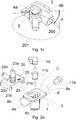
- Figures 1a, 1b , and 1c schematically illustrate an example of a first node element.
- the first node element 1 shown in these figures may be part of a lattice structure.
- the first node element 1 may be made of metal, fiber reinforced plastic, concrete, or other suitable material.
- the first node element 1 comprises a contact side 2 and a coupling side 3.
- the coupling side 3 comprises two hollow insertion channels 4a, 4b.
- Each channel may have the same diameter along the length of the channel.
- each channel may have a greater diameter at a first end at or near the contact side than the diameter at or near a second end opposite to the first end near the coupling side such that the diameter of the channel decreases along the longitudinal length of the channel. This way, each channel may be tapered, thus the insertion of a bar into the channel may be facilitated.
- some of the channels of the coupling side 3 may have the same diameter along the length of the channel and some other channels may have the shape of a funnel.
- the channels may have same or different diameters in order to allocate elongated members of different diameters.
- the channels may be integrally formed with the first node element 1.
- the channels may be coupled by suitable means to the coupling side 3 of the first node element 1.
- the channels 4a, 4b are tilted at an angle with respect to the coupling side 3 as shown in figure 1c .
- the angle is defined between the coupling side 3 and a longitudinal axis of the channels 4a, 4b.
- the angle may be any suitable angle that provides the insertion of a bar in the required position.
- the angle ⁇ of the longitudinal axis 200 of the channel 4b with respect to a plane defined by the coupling side 3 is shown.
- the longitudinal axis 200 (and thus the channel 4b) may further adopt any of the orientations represented by the circle 201.
- the longitudinal axis of channel 4a may be at e.g. 50 degrees with respect to the coupling side 3.
- the longitudinal axis 200 of channel 4b may be at e.g. 50 degrees with respect to the coupling side.
- the angle of the longitudinal axis of the channels 4a and 4b may be between 20 and 90 degrees with respect to the coupling side 3.
- the angle between the longitudinal axis of the channel 4a and the plane defined by the coupling side 3 and the angle between the longitudinal axis of the channel 4b and the plane defined by the coupling side 3 may be the same at each channel 4a, 4b. In some other examples, the angle of the channel 4a and the channel 4b may be different.
- channels 4a, 4b may be arranged such that the projections of their longitudinal axes on the plane of the coupling side 3 form an angle of between 180 and 20 degrees.
- the coupling side 3 may further comprise a mounting element 5 configured to receive an end of a hollow elongated bar.
- the mounting element 5 may comprise an elongated protrusion 5a having a hollow interior 5b and a stopper 5c.
- the protrusion 5a may be a solid protrusion.
- the mounting element 5 may be a blind hole prepared to receive an end of an elongated bar.
- mounting elements or “mounting surfaces” is to be understood as a mounting element where the hollow bars can be inserted.
- the stopper 5c may be specifically shaped to provide a seat for a bar of certain kind (as will be described in more detail in figures 6a - 6r )
- the hollow bar in question can thus be inserted in the protrusion 5a and be advanced until it encounters the seat 5c (or "stopper").
- the mounting element 5 may be tilted at an angle with respect to the coupling side 3, as shown in figure 1c for the channel 4b.
- the angle is defined between the plane defined by the coupling side 3 and a longitudinal axis of the mounting element 5.
- the angle of the mounting element with respect to the coupling side 3 may be 90 degrees, although some other suitable angles are possible, e.g. between 20 and 90 degrees with respect to the coupling side 3.
- the contact side 2 may further comprise an opening 6 configured to receive a retention element (not shown).
- a through-hole is thus formed between the opening 6 and the channels 4a, 4b.
- the channels 4a, 4b are shaped to provide the insertion of an elongated bar (not shown) of a certain kind or shape.
- the elongated bar in question can thus be inserted from the contact side 2 to the coupling side 3 by traversing the corresponding through-hole formed between the opening 6 and each channel 4a, 4b. Then, the elongated bar may be advanced until an end of the bar is inserted into the mounting surfaces of a second node element (not shown) previously situated, e.g. in a first level on the ground.
- the elongated bar can be easily attached to the first node element and the second node element (not shown), wherein the second node may be previously situated in a level different from the plane of the first node element, e.g. a first plane on the ground.
- This can be performed without the need of e.g. bolting, welding, gusset plates, or complex telescopic systems in the bar in order to attach the bar to the first and the second nodes.
- the bar is self-interlocked between the nodes. This leads to an installation of the bar in a simple manner. Additionally, the translational and rotational movements of the bar are restrained once the bar is coupled to the second node element.
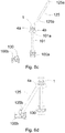
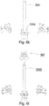
- Figure 2a schematically illustrates an exploded view of the first node element of figures 1a, 1b , and 1c comprising two retention screws 11a, 11b, a retention element 10, and a second node element 20.
- the same reference numbers denote the same elements as those in the figures 1a and 1b .
- the first node element may be provided with two hollow insertion channels 4a, 4b, wherein each channel is configured to receive one of the elongated bars, and an opening 6 configured to receive the retention element 10.
- the structure and operation of these elements may be the same as the one described for the first node element explained in figures 1a, 1b and 1c .
- retention means e.g. a first retention screw 11a and a second retention screw 11b may be provided.
- the retention screws 11a, 11b may be made of e.g. metal or plastic material.
- the structure and operation of the screw 11b is shown in more detail in figures 3a and 3b .
- a bar 125 has already been inserted into the channel 4b from the contact side to the coupling side traversing the corresponding through-hole (see Figure 3b ).
- the screw 11b comprises threads along its outer circumferential surface between the head portion 400 and the bottom portion 401.
- a first end 125a of the bar 125 may be provided with an internal screw thread 12.
- the channel 4b may be provided with a stopper 13.
- the stopper 13 may be specifically shaped to provide a seat for the screw 11b.
- the screw 11b in question can thus be inserted in the channel 4b through the corresponding through-hole formed between the channel 4a and the opening.
- the screw 11b may further be screwed into the first end 125a of the elongated bar until it encounters the seat 13 (or stopper).
- the bars can remain in place when tensile loads are applied to the node. Furthermore, the tensile strength of the connection between the bar and the channel 4b (and thus the first node element 1) may be improved. In some examples, instead of employing screws, one end of the bars may be countersunk or attached using a clip system to increase the tensile strength.
- the screws may be provided with outer threads at or near the head portion 400, thus the screw may further be bolted to a threaded inner part of the first node element (and thus a better resistance against compressive forces may be achieved).
- a second bar (not shown) can be secured inside the channel 4a (and thus inside the first node element 1) using a screw 11a.
- the structure and operation of the screw 11a may be the same as the one described for the screw 11b in figures 3a and 3b .
- the screws 11a and 11b in use i.e. when the first node element is attached to a second node element, may be hidden so they cannot be unscrewed while the first node 1 is attached to the bars (and also due to the fact that the lattice structure is self-interlocked and the opening covered by the second node element), thus providing additional protection against thief or sabotage.
- the resulting connector is in a visually attractive appearance.
- a second node element 20 may also be provided (see Figure 2a ).
- the second node element 20 may be made of metal, fiber reinforced plastic, or other suitable materials.
- the second node element may comprise a first groove 21a and a second groove 21b.
- the grooves may be integrally formed with the second node element 20 or attached by some means.
- the grooves 21a, 21b are a rail structure (also referred herein as a track or slot) shaped and sized for guiding, directing, retaining, attaching, edges 8a, 8b located at laterally opposite sides of the contact side 2 of the first node element 1.
- the grooves may be L-shaped, however some other forms are possible to better fit the edges 8a, 8b, e.g. rounded.
- the edges 8a, 8b may be slidably engaged with the grooves 21a, 21b, respectively. Therefore, the second node element 20 may be coupled to the first node element 1. Additionally, bolting, welding, or any other means may be used to increase the tensile resistance of the coupling between first and second node elements.
- the second node element may further comprise three mounting elements 23a, 23b, 23c.
- the structure of the mounting elements 23a, 23b, 23c may be the same as the one described for the mounting element 5 of the first node element described in figures 1a and 1b .
- the mounting elements 23a - 23c may be tilted at an angle with respect to the coupling side 22, as shown in figure 2b .
- the angle may be defined between the plane defined by the coupling side and a longitudinal axis of the mounting elements 23a - 23c.
- the longitudinal axis of the first mounting element 23a may be tilted at angle of 90 degrees with respect to the coupling side 22.
- the longitudinal axis 500 of the second mounting element 23b may be at an angle ⁇ of e.g. 50 degrees with respect to the coupling side 22.
- the mounting element 23b may further adopt any of the orientations represented by the circle 501.
- the longitudinal axis of the third mounting surface 23c may be at e.g.
- any suitable angle e.g. is possible depending on the desired orientation of each bar attached to each of the mounting elements 23a, 23b, 23c.
- the angle of the longitudinal axis of the mounting elements 23a and 23b with respect to the plane defined by the coupling side 22 may be between 20 and 90 degrees.
- the angle between the mounting element 23a and the coupling side 22 and the angle between the mounting element 23b and the coupling side 22 may be the same. In some other examples, the angle of the mounting element 23a and the mounting element 23b with respect to the coupling side 22 may be different angles.
- mounting elements 23a, 23b may be arranged such that the projections of their longitudinal axes on the plane of the coupling side 22 form an angle of between 20 and 180 degrees.
- the angle ⁇ shown in figure 1c and the angle ⁇ shown in figure 2b may be the same angle. In some other examples, the angle ⁇ and the angle ⁇ may be different angles.
- the first node element 1 may be provided with an opening 6 configured to receive a retention element.
- a retention element 10 may be provided.
- the retention element 10 may be made of metal, concrete, or plastic material.
- the material of the retention element 10 may be the same as the material of the first node element 1.
- the material of the first node element 1 and the material of the retention element 10 may be made of different materials.
- the retention element 10 may be rounded and it may comprise threads along its outer surface.
- the opening 6 may be provided with an internal screw thread. This way, the retention element 10 may be screwed to the opening 6. Therefore, the bars can remain in position in a proper manner. Furthermore, the compressive strength of the connection between the bar and the first node element may be improved. Moreover, the bars may remain in place without the presence of the second node element when compressive loads are applied to the node.
- the bars can be secured and fixed in position inside the respective channel 4a, 4b (and thus inside the first node element 1) using the retention element 10 and the second node element 20.
- the retention element 10 provides a suitable transmission of the compressive forces from the bars to the second node element.
- the elongated bars previously inserted into the openings 4a, 4b may be secured merely with the second node element 2, i.e. without requiring the retention element 10 or the screws 11a, 11b.
- the number of required parts per joint is reduced and the assembly is simpler.
- the bars may be further secured with the screws 11a, 11b to increase the resistance to tensile forces.
- the elongated bars may be further secured with the retention element 10 and the second node element 20 to also withstand compressive forces.
- the bars may be secured merely with the retention screws 11a, 11b and the second node element 20, thus the bars may properly remain in position without the retention element 10. This preserves compressive and tensile forces resistance while reducing the number of required parts and improving assembly simplicity.
- the second node element 20, the retention screws 11a, 11b, and the retention element 10 could be pre-assembled with the first node element 1, thus forming a pre-assembled kit.
- the first node element, the second node element 20, the retention screws 11a, 11b and the retention element 10 can be delivered separately as a set of parts, in which case the personnel mounting the node, once the bars are inserted from the contact side to the coupling side traversing the corresponding through-hole formed between the opening 6 an the channels 4a, 4b, introduces the retention screws 11a, 11b through the channels and, subsequently, inserts the retention element 10 in the opening 6. Then, the second node element 20 may be connected to the first node element 1 in preparation for use.
- FIG. 4 schematically illustrates another example of a second node element and a retention element.
- a first node element 1 may be provided (which may be a similar first node element as described before).
- a high retention element 10 may be provided.
- a portion 10a of the high retention element 10 may protrude over the opening of the first node element 1.
- a second node element 700 may also be provided. Differently as before, the second node element 700 may be provided with an opening 83 in the contact side 701, wherein the opening 83 is configured to mate with the protruding portion 10a. This way, the relative motion between first and second node elements along the plane of the coupling side may be restrained by simple means.
- the structure and operation of the high retention element 10 may be the same as previously described.
- the bars may be introduced through the corresponding through-hole formed between the opening of the first node element and the channels 4a, 4b.
- a retention element 10 may be introduced into the opening 6 of the first node element. Once the retention element 10 is inserted, the portion 10a of the retention element 10 may protrude over the first node element 1.
- the second node element 700 may be brought in proximity of the first node element in the direction of the arrow.
- the contact side 701 of the second node element 700 may be situated over the contact side 2 of the first node element such that the protruding portion 10a of the retention element mates with the opening 83 of the second node element.
- the second node element 700 and the first node element 1 may be further secured to each other using, for example, bolts or studs (not shown).
- the bolts may be introduced into the corresponding holes 84a, 84b, 84c.
- the bolts can be tightened with suitable means, e.g. nuts (not shown), thus fixing the second node element 700 to the first node element 1.
- suitable means e.g. nuts (not shown)
- the second node element 700 and the first node element 1 may further be secured together by welding or any other means.
- the protruding portion inserted into the opening 83 may lead to a better performance of the node against lateral and compressive loads.
- the bolting or welding connection between the second node element 700 and the first node element 1 may lead to an improved withstand of tensile loads.
- Figure 5 schematically illustrates yet another example of a first node element.
- a first node element 90 may be provided. It differs from the first node element of the previous figures in that the first node element 90 of this example comprises a first recess 15a and a second recess 15b.
- the recesses 15a, 15b may be located on the contact side 2 of the first node element 90.
- the recesses 15a, 15b may located at or near lateral opposite sides of the contact side surface, however any suitable position over the contact surface 2 is possible.
- the recesses may be configured to receive a first end of an auxiliary elongated bar.
- a solid and elongated auxiliary bar 19 may be provided.
- the bar 19 may extend from a first end 19a to a second end 19b.
- the first end 19a of the bar 19 may be inserted and fitted into the recess 15b.
- the remainder of the structure of the first node element 90 may be substantially the same as described before.
- the second end 19b of the bar 19 may be attached to another recess (not shown) located over the contact surface of another first node element (not shown) in the lattice structure.
- Figures 6a - 6r schematically illustrate a sequence of situations that may occur during the performance of a method for assembling a lattice structure according to an example. Same reference numbers denote the same elements as those in the previous figures. The method is described below with reference to the sequences of situations illustrated by figures 6a -6r .
- the figure 6a illustrates an example of an initial situation.
- a second node element 100a and a second node element 100b are provided.
- Each second node element 100a, 100b may be similar to the second node elements shown in previous examples.
- the node elements may be situated at a permanent and fixed position in a first plane or level, e.g. on the floor.
- a first hollow bar 101 may be provided.
- the first bar 101 may extend from a first end 101a to a second end 101 b.
- the material choices for the first bar 101 may be any suitable material depending on application and manufacturing factors. Typical materials for use in the first bar include steel, aluminum, and carbon or glass fiber reinforced plastics among others. Where higher performance requirements are present, carbon fiber reinforced plastics are employed for the bars. Graphite materials and titanium are materials best suited for space applications where dimensional stability is often a requirement. Additionally, the bar 101 may have different diameters depending on the expected uses of the lattice structure to be formed.
- the second end 101b of the bar may be brought near to a first mounting element 102 of the second node element 100a. This way, the bar 101 is ready to be inserted in an elongated protrusion 107 until the end 101b reaches the stopper 108.
- the elongated protrusion 107 may have a suitable diameter in order to be inserted into a lumen of the hollow bar in the direction of the arrow.
- the elongated protrusion 107 may further have a very low coefficient of friction, thus the insertion and the removal of the bar may be improved.
- the elongated protrusion 107 may have a tapered end to facilitate the insertion.
- the end 101b of the bar 101 may further be screwed to a threaded elongated protrusion 107 to improve tensile strength.
- the hollow bar may be introduced into an elongated protrusion 107 of the mounting element 102 in the direction of the arrow until the end reaches the stopper 108, thus indicating that the bar has been properly placed on the second node element 100a.
- a first node element 1 may be provided.
- the first node element 1 may be similar to the first node element described in previous examples.
- the first node element 1 may comprise a mounting element 5.
- the mounting element may comprise an elongated protrusion 5a and a stopper 5c.
- the protrusion 5a may be introduced into the end 101a of the elongated bar 101 until the end 101a reaches the stopper 5c. This way, the first node element 1 may properly be attached to the bar 101.
- a second bar 125 may be provided.
- the bar may extend from a first end 125a to a second end 125b.
- the first node element 1 may be provided with an opening.
- the opening may be communicated with the first channel 4a.
- a through-hole is thus formed between the opening and the first channel 4a.
- the bar 125 may thus be introduced through the through-hole (and thus through the opening and the first channel 4a) in the direction of the arrow until the lumen of a second end 125b of the hollow bar is introduced in a mounting surface 130 of a second node element 100b.
- the end 125b may be screwed to the mounting surface 130 in order to improve tensile strength.
- the bar 125 has already been inserted through the through-hole of the first node 1 (and thus through the first channel 4a) and a second end 125b of the bar 125 has already been introduced in the mounting surface 130 until a stopper is reached. Thus, the bar 125 has been properly installed.
- a bar 126 may be provided.
- the structure of the bar 126 may be similar to the bar 125.
- the opening 6 and the channel 4b may be communicated forming a corresponding through-hole.
- the bar 126 may thus be introduced through the through-hole formed in the direction of the arrow until the lumen of the second end 126b of the hollow bar is introduced in a mounting element 250 of a second node element 100c.
- the bars 125, 126 may have tapered ends for better insertion through the channels.
- the bars 125, 126 may be installed by some means to a mounting element located, e.g. on the floor or a first node element instead of the second node elements.
- first and second retention screws as described in previous examples may be provided.
- the retention screws may be introduced into the corresponding channels as shown in figures 3a and 3b .
- the first node element may be provided with recesses as shown in figure 5 .
- auxiliary elongated bars as hereinbefore described may also be installed before a second node element is installed.
- a second node element 70 may be provided.
- the second node element 70 may be similar to the second node element disclosed in figure 2a .
- the second node element may be attached e.g. slidably attached to the first node element.
- the second node element is installed at a second level (different from the first level).
- FIG 6i schematic side and top views of the lattice structure are shown.
- the shadowed elements denote the elements which have already been assembled in the sequence of situations occurred in figures 6a - 6h .
- a bar 300 may be provided.
- the bar 300 is installed in the second node element 100b in the direction of the arrow.
- the second node element 70 has already been installed at a second level.
- a further second node element 75 is provided at the second level that may have been installed as described in figures 6a - 6h .
- a first node element 90 is installed at a third level at one end of the bar 300 in the direction of the arrow.
- the first node element 90 has already been installed to an end of the bar.
- bars 310 and 320 are provided.
- the bars 310, 320 may be introduced through the corresponding through-hole of the first node element 90 in the direction of the corresponding arrow. Once the bars are introduced, one end of the bar 310 may be attached to the second node element 75. Similarly, one end of the bar 320 may be attached to the second node element 70.
- a retention element 210 is ready to be placed into the opening 6 of the first node element of the third level in the direction of the arrow.
- a second node element 380 may be provided.
- the second node element 380 may be similar to the second node element disclosed in figures 2a , 2b .
- the second node element 380 may be attached (e.g. slidably attached) to the first node element 90 in the third level.
- a further bar 330 is provided.
- a first end of the bar may be brought near to a first mounting element of the second node element 75 of the second level. This way, the bar 330 is ready to be inserted in the direction of the arrow in an elongated protrusion until the end reaches a stopper.
- the first end of the bar 330 may be installed (not shown) in the first mounting element of the second node element 75 of the second level.
- the second end of the bar 330 is ready for the installation of the next first node element at a fourth level (not shown).
- figure 6r it is shown a schematic side view of the lattice structure.
- the shadowed elements denote the elements which have already been assembled in the sequence of situations occurred in figures 6a - 6q .
- first and second node elements and bars forming the lattice structure may be attached in the same way.
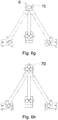
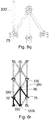
- Figure 7 shows another example of a lattice structure using the first and second node elements as hereinbefore described. Particularly, the first node element and auxiliary bars illustrated in figure 5 are used here. Auxiliary bars are used to connect neighboring nodes in the same level.
- FIG 8 shows yet another example of a lattice structure using examples of first and second node elements.
- each first node element comprises a single channel and a single mounting element. It differs from the example of figure 7 in that the mounting element is a blind hole instead of an elongated protrusion.
- auxiliary bars are used here.
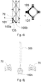
- Figures 9a - 9c schematically illustrate an example of a first node element, a further first node element and a high retention element.
- a first node element 111 may be provided (which may be the same or similar to a first node element as hereinbefore described).
- a high retention element 110 may be provided.
- the high retention element 110 may comprise a first portion 110a and a second portion 110b. In examples, the portions may be integrally formed.
- an opening 111a of the first node element may be tilted at an angle ⁇ 1 with respect to the coupling side of the first node element.
- the angle may be defined between the coupling side and a longitudinal axis of the opening 111a.
- the angle ⁇ 1 may be any suitable angle that provides the insertion of a bar and / or the high retention element in the required position.
- the opening 111a has the proper shape to mate with the first portion 110a of the retention element 110.
- the high retention element 110 may thus be inserted in the direction of the arrow (arrow A) into an opening 111a of the first node element 111.
- the high retention element 110 has already been introduced into the opening.
- the second portion 110b of the high retention element 110 may protrude over the opening 111a and the contact side 111b of the first node element 111.
- a further first node element 112 may be provided instead of a second node element.
- the first node element 112 may be the same or similar to a first node element as hereinbefore described.
- the first node element 112 may be provided with an opening 112a in the contact side 112b and hollow insertion channels, wherein the opening 112a and the channels are configured to mate with the portion 110b.
- the first node element 112 may be displaced in the direction of the arrow (arrow B).
- the portion 110b of the high retention element may thus be inserted into the opening of the first node element 112.
- the second portion 110b of the high retention element may be at an angle ⁇ 2 with respect to a plane defined by the coupling side of the first node element 111.
- the angle ⁇ 2 may be defined between the coupling side of the first node element and a longitudinal axis of the second portion of the high retention element.
- the first node element 112 may thus be displaced towards the retention element 110 in the direction of the arrow (arrow B) thereby inserting the protruding portion 110b into the corresponding opening 112a at the desired position.
- the first node element 112 may properly be attached to the first node element 111.
- the contact side 112b of the first node element 112 may be situated over the contact side 111b of the first node element 111 such that the portion 110b of the retention element 110 mates with the opening and the corresponding passages of the first node element 112.
- the first node elements 111, 112 may be entirely secured to each other in e.g. an assembled lattice structure by simple means and without additional parts, thus saving time and materials.
- the first node elements 111, 112 may further be secured to each other using e.g. bolts, studs, or welding.
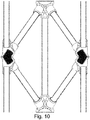
- Figure 10 shows a further example of an assembled lattice structure including longitudinal cross-sectional views of the first node element, the further first node element and the high retention element of figures 9a - 9c .
- Auxiliary bars may be used to connect neighboring nodes in the same level, as previously described (not shown).
- first node element and a further first node element described in figures 9a - 9f , 10 and disclosed above may be combined with the attachment of a first node element and a second node element as described in figures 1 - 8 in order to form e.g. a lattice structure.
Description
- This application claims the benefit of European Patent Application
EP16382555.7 filed November 24, 2016 - Lattice structures may be described as networks of intersecting elongated bars joined together using connecting means, e.g. nodes at their intersection points. It is well known that the highest buckling resistance of these structures is generally achieved using bars with clamped ends, wherein the translational and rotational movements of the bars are restrained, in contrast to pinned ends where only translational movements of the bars are fixed. Furthermore, resultant forces should converge into a single point, i.e. a non-eccentric point, to prevent additional moments and shear forces that may reduce the resistance of the joint.
- The most popular means to obtain non-eccentric joints with clamped bar ends are welding or bolting, that generally require gusset plates and specific tools. Another popular means employ nodal connectors to secure the bars and to obtain stable structures.
- A known connector for the above purpose comprises a screw bolt at each end of each bar that can be axially advanced or withdrawn along the bar. In a completely assembled state, the screw bolt at each end of the bar can be advanced (and thus inserted) by appropriate operation into a corresponding mounting surface of the node. Therefore, when screw bolts of the bar are adjusted axially in opposite directions by suitable relative movement, the bars are properly connected to the nodes.
- A further known connector comprises integral cylindrical hubs with serrated keyways and bars with their ends pressed to form a coined edge, wherein the coin edge is inserted into the keyways of the hub. To secure the bars, washers are placed at each end of the hub and a screw bolt is passed through the center of the hub.
- The document
US4353662 discloses a joint system comprising thick spherical shell connectors, wherein the connectors are opened at their bottom to permit bolt insertion and screwing. The structural members are hollow bars having conical ends welded to both ends of the tube. End cones have threaded holes ready to receive the corresponding bolts. Moreover, other systems even do not need a node element to join the bars. For example, the documentEP0214137 describes that the chord members are continuous at the intersections. Furthermore, overlapping members meeting at the intersections are flattened to be fastened with pads and bolts. -
GB 1352511 claim 1, and further discloses a junction member comprising four threaded holes equally inclined to and symmetrically distributed about an axis. The member has a skirt which is welded to a plate. Struts are connected to the member either directly or by screw threaded studs and form the sides of a pyramidal unit. - Despite of the extensive use of welding, bolting, and the aforementioned arrangements as general jointing systems, all of them may experience one or more of the following disadvantages. The strength of the bars may be compromised at their ends as a consequence of the special features required for mating, e.g. flattened or conical bar ends. This intrinsic weakness of the connections may be minimized by increasing the thicknesses of both bars and node elements, thus leading to increased material costs and reduced weight efficiency. Moreover, some mating features usually require welding, milling, threading, or some combination of them for their fabrication, which may greatly contribute to increase expenditures. Regarding the buckling behavior, in all these arrangements, bar ends are generally modeled as pinned instead of clamped (the more favorable case), mainly because the connection cannot withstand large bending moments. This may be compensated by using thicker components that increases weight and material costs even more. The more traditional welding or bolting assembly methods are costly, especially in terms of time and labor, and usually require gusset plates and specific scaffolding or complex alignment tools that further increase expenditures. Furthermore, the disassembly or decommissioning cost of aforementioned assembly methods is generally high, in particular for welded and / or bolted structures.
- Examples of the present disclosure seek to at least partially reduce one or more of the aforementioned problem.
- A kit comprising the features according to
claim 1 is provided to solve the aforementioned problem. - With such an arrangement, the bars can be inserted through the corresponding through-hole and installed in a simple and fast manner. Once the elongated bars are inserted through the corresponding through-hole (and thus installed), the elongated bars are self-interlocked by simple means instead of more traditional connections that require additional use of axially displaceable screw bolts, gusset plates, or welding.
- In a second aspect, a second node element for attaching one or more elongated bars forming a lattice structure is provided. The second node element may comprise a coupling side and a contact side. The coupling side may comprise one or more mounting elements, wherein each mounting element is configured to couple an end of a bar.
- In a further aspect, a kit is provided including at least a first node element according to any of the examples described herein and at least a second node element according to any of the examples described herein.
- In yet a further aspect, a method for assembling a lattice structure is provided. At least one first node element according to any of the examples described herein is provided. Furthermore, at least one second node element according to any of the examples described herein is provided. Additionally, one or more bars are provided. The method comprises inserting the bars through the hollow insertion channels of the first node element from the contact side to the coupling side by traversing the corresponding through-hole until an end of the bars is attached to a mounting element of the second node element.
- According to this aspect, the bars are inserted and self-interlocked with respect to the first and the second node elements in a time-efficient way by simple means. This is performed without complex tools or heavy cranes. Besides, the inter-locked lattice structure provides an improved security against thief or sabotage.
- In some examples, the method further comprises securing a second node element to the first node element after inserting the bars through the hollow insertion channels of the first node element.
- This way, upon installation of the bars and securing the first node element to the second node element, the translational and the rotational movements of the bars are restrained (instead of traditional pinned solutions, wherein only the translational movements are restrained), thus buckling resistance of the bars under compressive loads is optimized. Additionally, a strong and stiff attachment between the bars and the node elements by simple means is achieved.
- In summary, securing the first node element to the second node element after inserting the bars through the hollow insertion channels of the first node element from the contact side to the coupling side by traversing the corresponding through-hole until an end of the bars is attached to a mounting element of the second node element provides a strong, versatile, fast, and simple assembly method. The use of complex and time-consuming connections, e.g. extendable pin connections, bolting, welding, or gusset plates for assembly is avoided. Additionally, all parts can be fabricated repetitively by standard and inexpensive techniques, e.g. metal casting or plastic injection molding. Furthermore, the same assembling method is employed regardless of the elongated bars shape, thus providing a particularly versatile assembly. Moreover, eccentric or non-eccentric unions can be designed as required.
- Non-limiting examples of the present disclosure will be described in the following, with reference to the appended drawings, in which:
-
Figure 1a, figure 1b , andfigure 1c schematically illustrate an example of a first node element; -
Figure 2a schematically illustrates an exploded view of the first node element offigures 1a - 1c comprising a retention element, two retention screws, and a second node element; -
Figure 2b schematically illustrates an example of the second node element offigure 2a ; -
Figures 3a and 3b illustrates a cross-section of the first node element comprising one of the screws offigure 2a ; -
Figure 4 schematically illustrates another example of a first node element and a second node element; -
Figure 5 schematically illustrates yet another example of a first node element and an auxiliary bar; -
Figures 6a - 6r schematically illustrate a sequence of situations that may occur during the performance of a method for assembling a lattice structure; -
Figure 7 shows an example of a lattice structure; -
Figure 8 shows another example of a lattice structure; -
Figures 9a - 9c schematically illustrate an example of a first node element, a further first node element and a high retention element; -
Figures 9d - 9f show longitudinal cross-sectional views of the first node element, the further first node element and the high retention element offigures 9a - 9c ; -
Figure 10 shows a further example of an assembled lattice structure including longitudinal cross-sectional views of the first node elements and the high retention element offigures 9a - 9c . - Along the present description and claims the term "elongated bars" is to be understood as tubes, profiles, struts, chords, braces, girders, or any other similar structural member that may be used in lattice structures to the same purpose.
-
Figures 1a, 1b , and1c schematically illustrate an example of a first node element. Thefirst node element 1 shown in these figures may be part of a lattice structure. Thefirst node element 1 may be made of metal, fiber reinforced plastic, concrete, or other suitable material. - The
first node element 1 comprises acontact side 2 and acoupling side 3. In this example, thecoupling side 3 comprises twohollow insertion channels - Each channel may have the same diameter along the length of the channel. In some other examples, each channel may have a greater diameter at a first end at or near the contact side than the diameter at or near a second end opposite to the first end near the coupling side such that the diameter of the channel decreases along the longitudinal length of the channel. This way, each channel may be tapered, thus the insertion of a bar into the channel may be facilitated. In some other examples, some of the channels of the
coupling side 3 may have the same diameter along the length of the channel and some other channels may have the shape of a funnel. Furthermore, the channels may have same or different diameters in order to allocate elongated members of different diameters. - The channels may be integrally formed with the
first node element 1. In alternative examples, the channels may be coupled by suitable means to thecoupling side 3 of thefirst node element 1. - The
channels coupling side 3 as shown infigure 1c . The angle is defined between thecoupling side 3 and a longitudinal axis of thechannels figure 1c , the angle α of thelongitudinal axis 200 of thechannel 4b with respect to a plane defined by thecoupling side 3 is shown. The longitudinal axis 200 (and thus thechannel 4b) may further adopt any of the orientations represented by thecircle 201. In this particular example, the longitudinal axis ofchannel 4a may be at e.g. 50 degrees with respect to thecoupling side 3. Moreover, thelongitudinal axis 200 ofchannel 4b may be at e.g. 50 degrees with respect to the coupling side. However, in some other examples, the angle of the longitudinal axis of thechannels coupling side 3. - In this particular example, the angle between the longitudinal axis of the
channel 4a and the plane defined by thecoupling side 3 and the angle between the longitudinal axis of thechannel 4b and the plane defined by thecoupling side 3 may be the same at eachchannel channel 4a and thechannel 4b may be different. - Additionally, the
channels coupling side 3 form an angle of between 180 and 20 degrees. - The
coupling side 3 may further comprise a mountingelement 5 configured to receive an end of a hollow elongated bar. Particularly, as shown infigure 1b , the mountingelement 5 may comprise anelongated protrusion 5a having ahollow interior 5b and astopper 5c. In some examples, theprotrusion 5a may be a solid protrusion. In other examples, the mountingelement 5 may be a blind hole prepared to receive an end of an elongated bar. - Along the present description and claims "mounting elements" or "mounting surfaces" is to be understood as a mounting element where the hollow bars can be inserted.
- The
stopper 5c may be specifically shaped to provide a seat for a bar of certain kind (as will be described in more detail infigures 6a - 6r ) The hollow bar in question can thus be inserted in theprotrusion 5a and be advanced until it encounters theseat 5c (or "stopper"). - Similarly as before, the mounting
element 5 may be tilted at an angle with respect to thecoupling side 3, as shown infigure 1c for thechannel 4b. The angle is defined between the plane defined by thecoupling side 3 and a longitudinal axis of the mountingelement 5. In this example, the angle of the mounting element with respect to thecoupling side 3 may be 90 degrees, although some other suitable angles are possible, e.g. between 20 and 90 degrees with respect to thecoupling side 3. - Again in
figure 1a , thecontact side 2 may further comprise anopening 6 configured to receive a retention element (not shown). A through-hole is thus formed between theopening 6 and thechannels - The
channels contact side 2 to thecoupling side 3 by traversing the corresponding through-hole formed between theopening 6 and eachchannel - With such an arrangement, the elongated bar can be easily attached to the first node element and the second node element (not shown), wherein the second node may be previously situated in a level different from the plane of the first node element, e.g. a first plane on the ground. This can be performed without the need of e.g. bolting, welding, gusset plates, or complex telescopic systems in the bar in order to attach the bar to the first and the second nodes. Moreover, the bar is self-interlocked between the nodes. This leads to an installation of the bar in a simple manner. Additionally, the translational and rotational movements of the bar are restrained once the bar is coupled to the second node element.
-
Figure 2a schematically illustrates an exploded view of the first node element offigures 1a, 1b , and1c comprising tworetention screws retention element 10, and asecond node element 20. In this figure, the same reference numbers denote the same elements as those in thefigures 1a and 1b . Also here the first node element may be provided with twohollow insertion channels opening 6 configured to receive theretention element 10. The structure and operation of these elements may be the same as the one described for the first node element explained infigures 1a, 1b and1c . - In this particular example, retention means e.g. a
first retention screw 11a and asecond retention screw 11b may be provided. The retention screws 11a, 11b may be made of e.g. metal or plastic material. - The structure and operation of the
screw 11b is shown in more detail infigures 3a and 3b . In this example, abar 125 has already been inserted into thechannel 4b from the contact side to the coupling side traversing the corresponding through-hole (seeFigure 3b ). Thescrew 11b comprises threads along its outer circumferential surface between thehead portion 400 and thebottom portion 401. Afirst end 125a of thebar 125 may be provided with aninternal screw thread 12. - Moreover, the
channel 4b may be provided with astopper 13. Thestopper 13 may be specifically shaped to provide a seat for thescrew 11b. Thescrew 11b in question can thus be inserted in thechannel 4b through the corresponding through-hole formed between thechannel 4a and the opening. Thescrew 11b may further be screwed into thefirst end 125a of the elongated bar until it encounters the seat 13 (or stopper). - With the use of screws, the bars can remain in place when tensile loads are applied to the node. Furthermore, the tensile strength of the connection between the bar and the
channel 4b (and thus the first node element 1) may be improved. In some examples, instead of employing screws, one end of the bars may be countersunk or attached using a clip system to increase the tensile strength. - In some other examples, the screws may be provided with outer threads at or near the
head portion 400, thus the screw may further be bolted to a threaded inner part of the first node element (and thus a better resistance against compressive forces may be achieved). - Similarly, a second bar (not shown) can be secured inside the
channel 4a (and thus inside the first node element 1) using ascrew 11a. The structure and operation of thescrew 11a may be the same as the one described for thescrew 11b infigures 3a and 3b . - Furthermore, the
screws first node 1 is attached to the bars (and also due to the fact that the lattice structure is self-interlocked and the opening covered by the second node element), thus providing additional protection against thief or sabotage. Moreover, the resulting connector is in a visually attractive appearance. - A
second node element 20 may also be provided (seeFigure 2a ). Similarly, as the first node element, thesecond node element 20 may be made of metal, fiber reinforced plastic, or other suitable materials. The second node element may comprise afirst groove 21a and asecond groove 21b. The grooves may be integrally formed with thesecond node element 20 or attached by some means. In this particular example, thegrooves edges contact side 2 of thefirst node element 1. In this example, the grooves may be L-shaped, however some other forms are possible to better fit theedges edges grooves second node element 20 may be coupled to thefirst node element 1. Additionally, bolting, welding, or any other means may be used to increase the tensile resistance of the coupling between first and second node elements. - The second node element may further comprise three mounting
elements elements element 5 of the first node element described infigures 1a and 1b . - Similarly as before, the mounting
elements 23a - 23c may be tilted at an angle with respect to thecoupling side 22, as shown infigure 2b . The angle may be defined between the plane defined by the coupling side and a longitudinal axis of the mountingelements 23a - 23c. In this example, the longitudinal axis of the first mountingelement 23a may be tilted at angle of 90 degrees with respect to thecoupling side 22. Thelongitudinal axis 500 of the second mountingelement 23b may be at an angle β of e.g. 50 degrees with respect to thecoupling side 22. The mountingelement 23b may further adopt any of the orientations represented by the circle 501.The longitudinal axis of the third mountingsurface 23c may be at e.g. 50 degrees with respect to thecoupling side 22. However, any suitable angle e.g. is possible depending on the desired orientation of each bar attached to each of the mountingelements elements coupling side 22 may be between 20 and 90 degrees. - In this particular example, the angle between the mounting
element 23a and thecoupling side 22 and the angle between the mountingelement 23b and thecoupling side 22 may be the same. In some other examples, the angle of the mountingelement 23a and the mountingelement 23b with respect to thecoupling side 22 may be different angles. - Additionally, the mounting
elements coupling side 22 form an angle of between 20 and 180 degrees. - In some examples, the angle α shown in
figure 1c and the angle β shown infigure 2b may be the same angle. In some other examples, the angle α and the angle β may be different angles. - Also in
figure 2a , as commented above, thefirst node element 1 may be provided with anopening 6 configured to receive a retention element. Aretention element 10 may be provided. Theretention element 10 may be made of metal, concrete, or plastic material. The material of theretention element 10 may be the same as the material of thefirst node element 1. Alternatively, the material of thefirst node element 1 and the material of theretention element 10 may be made of different materials. - In some examples, the
retention element 10 may be rounded and it may comprise threads along its outer surface. In this particular example, theopening 6 may be provided with an internal screw thread. This way, theretention element 10 may be screwed to theopening 6. Therefore, the bars can remain in position in a proper manner. Furthermore, the compressive strength of the connection between the bar and the first node element may be improved. Moreover, the bars may remain in place without the presence of the second node element when compressive loads are applied to the node. - Again, once the elongated bars (not shown) are inserted into the
hollow insertion channels respective channel retention element 10 and thesecond node element 20. Furthermore, theretention element 10 provides a suitable transmission of the compressive forces from the bars to the second node element. - In some examples, the elongated bars previously inserted into the
openings second node element 2, i.e. without requiring theretention element 10 or thescrews - In some other examples, the bars may be further secured with the
screws screws figures 3a and 3b , the elongated bars may be further secured with theretention element 10 and thesecond node element 20 to also withstand compressive forces. - In yet further examples, the bars may be secured merely with the
retention screws second node element 20, thus the bars may properly remain in position without theretention element 10. This preserves compressive and tensile forces resistance while reducing the number of required parts and improving assembly simplicity. - Particularly in this
figure 2a , thesecond node element 20, theretention screws retention element 10 could be pre-assembled with thefirst node element 1, thus forming a pre-assembled kit. Alternatively, the first node element, thesecond node element 20, theretention screws retention element 10 can be delivered separately as a set of parts, in which case the personnel mounting the node, once the bars are inserted from the contact side to the coupling side traversing the corresponding through-hole formed between theopening 6 an thechannels retention screws retention element 10 in theopening 6. Then, thesecond node element 20 may be connected to thefirst node element 1 in preparation for use. -
Figure 4 schematically illustrates another example of a second node element and a retention element. Afirst node element 1 may be provided (which may be a similar first node element as described before). Moreover, ahigh retention element 10 may be provided. In this example, aportion 10a of thehigh retention element 10 may protrude over the opening of thefirst node element 1. Asecond node element 700 may also be provided. Differently as before, thesecond node element 700 may be provided with anopening 83 in thecontact side 701, wherein theopening 83 is configured to mate with the protrudingportion 10a. This way, the relative motion between first and second node elements along the plane of the coupling side may be restrained by simple means. The structure and operation of thehigh retention element 10 may be the same as previously described. - Similarly as before, the bars may be introduced through the corresponding through-hole formed between the opening of the first node element and the
channels retention element 10 may be introduced into theopening 6 of the first node element. Once theretention element 10 is inserted, theportion 10a of theretention element 10 may protrude over thefirst node element 1. Thesecond node element 700 may be brought in proximity of the first node element in the direction of the arrow. Thecontact side 701 of thesecond node element 700 may be situated over thecontact side 2 of the first node element such that the protrudingportion 10a of the retention element mates with theopening 83 of the second node element. - Additionally, the
second node element 700 and thefirst node element 1 may be further secured to each other using, for example, bolts or studs (not shown). The bolts may be introduced into the correspondingholes second node element 700 to thefirst node element 1. In some other examples, thesecond node element 700 and thefirst node element 1 may further be secured together by welding or any other means. - With such an arrangement, the protruding portion inserted into the
opening 83 may lead to a better performance of the node against lateral and compressive loads. At the same time, the bolting or welding connection between thesecond node element 700 and thefirst node element 1 may lead to an improved withstand of tensile loads. -
Figure 5 schematically illustrates yet another example of a first node element. Afirst node element 90 may be provided. It differs from the first node element of the previous figures in that thefirst node element 90 of this example comprises afirst recess 15a and asecond recess 15b. Therecesses contact side 2 of thefirst node element 90. Therecesses contact surface 2 is possible. - The recesses may be configured to receive a first end of an auxiliary elongated bar. In this example, a solid and elongated
auxiliary bar 19 may be provided. Thebar 19 may extend from afirst end 19a to asecond end 19b. Thefirst end 19a of thebar 19 may be inserted and fitted into therecess 15b. The remainder of the structure of thefirst node element 90 may be substantially the same as described before. - The
second end 19b of thebar 19 may be attached to another recess (not shown) located over the contact surface of another first node element (not shown) in the lattice structure. -
Figures 6a - 6r schematically illustrate a sequence of situations that may occur during the performance of a method for assembling a lattice structure according to an example. Same reference numbers denote the same elements as those in the previous figures. The method is described below with reference to the sequences of situations illustrated byfigures 6a -6r . - The
figure 6a illustrates an example of an initial situation. In this figure, asecond node element 100a and asecond node element 100b are provided. Eachsecond node element - In this figure, a first
hollow bar 101 may be provided. Thefirst bar 101 may extend from afirst end 101a to asecond end 101 b. - The material choices for the
first bar 101 may be any suitable material depending on application and manufacturing factors. Typical materials for use in the first bar include steel, aluminum, and carbon or glass fiber reinforced plastics among others. Where higher performance requirements are present, carbon fiber reinforced plastics are employed for the bars. Graphite materials and titanium are materials best suited for space applications where dimensional stability is often a requirement. Additionally, thebar 101 may have different diameters depending on the expected uses of the lattice structure to be formed. - The
second end 101b of the bar may be brought near to a first mountingelement 102 of thesecond node element 100a. This way, thebar 101 is ready to be inserted in anelongated protrusion 107 until theend 101b reaches thestopper 108. - The
elongated protrusion 107 may have a suitable diameter in order to be inserted into a lumen of the hollow bar in the direction of the arrow. Theelongated protrusion 107 may further have a very low coefficient of friction, thus the insertion and the removal of the bar may be improved. Theelongated protrusion 107 may have a tapered end to facilitate the insertion. Theend 101b of thebar 101 may further be screwed to a threadedelongated protrusion 107 to improve tensile strength. - Once the
bar 101 is situated at the desired position, the hollow bar may be introduced into anelongated protrusion 107 of the mountingelement 102 in the direction of the arrow until the end reaches thestopper 108, thus indicating that the bar has been properly placed on thesecond node element 100a. - In
figure 6b , afirst node element 1 may be provided. Thefirst node element 1 may be similar to the first node element described in previous examples. Thefirst node element 1 may comprise a mountingelement 5. The mounting element may comprise anelongated protrusion 5a and astopper 5c. - Similarly as before, the
protrusion 5a may be introduced into theend 101a of theelongated bar 101 until theend 101a reaches thestopper 5c. This way, thefirst node element 1 may properly be attached to thebar 101. - In
figure 6c , asecond bar 125 may be provided. The bar may extend from afirst end 125a to asecond end 125b. - As previously commented, the
first node element 1 may be provided with an opening. The opening may be communicated with thefirst channel 4a. A through-hole is thus formed between the opening and thefirst channel 4a. - The
bar 125 may thus be introduced through the through-hole (and thus through the opening and thefirst channel 4a) in the direction of the arrow until the lumen of asecond end 125b of the hollow bar is introduced in a mountingsurface 130 of asecond node element 100b. Similarly as before, in some examples, theend 125b may be screwed to the mountingsurface 130 in order to improve tensile strength. - In
figure 6d , thebar 125 has already been inserted through the through-hole of the first node 1 (and thus through thefirst channel 4a) and asecond end 125b of thebar 125 has already been introduced in the mountingsurface 130 until a stopper is reached. Thus, thebar 125 has been properly installed. - In
figure 6e , abar 126 may be provided. The structure of thebar 126 may be similar to thebar 125. - As previously commented, the
opening 6 and thechannel 4b may be communicated forming a corresponding through-hole. Thebar 126 may thus be introduced through the through-hole formed in the direction of the arrow until the lumen of thesecond end 126b of the hollow bar is introduced in a mountingelement 250 of asecond node element 100c. - In some examples, the
bars - In
figure 6f , thebar 126 has already been inserted through the through-hole of the first node 1 (and thus through thesecond channel 4b) and anend 126b of thebar 126 has already been introduced in a mounting element until a stopper is reached. Thus, thebar 126 has been properly installed. - In some examples, the
bars - In
figure 6g , the bars have already been installed. Aretention element 10 as described in previous figures may be provided. At this moment, theretention element 10 may be placed into theopening 6. - In some examples not shown, previously to the insertion of the
retention element 10 into theopening 6, a first and second retention screws as described in previous examples may be provided. The retention screws may be introduced into the corresponding channels as shown infigures 3a and 3b . - In yet further examples not shown, the first node element may be provided with recesses as shown in
figure 5 . Thus, auxiliary elongated bars as hereinbefore described may also be installed before a second node element is installed. - In
figure 6h , asecond node element 70 may be provided. Thesecond node element 70 may be similar to the second node element disclosed infigure 2a . The second node element may be attached e.g. slidably attached to the first node element. Thus, the second node element is installed at a second level (different from the first level). - In
figure 6i , schematic side and top views of the lattice structure are shown. The shadowed elements denote the elements which have already been assembled in the sequence of situations occurred infigures 6a - 6h . - In
figure 6j , abar 300 may be provided. Thebar 300 is installed in thesecond node element 100b in the direction of the arrow. As previously commented, thesecond node element 70 has already been installed at a second level. Moreover, a furthersecond node element 75 is provided at the second level that may have been installed as described infigures 6a - 6h . - In
figure 6k , thebar 300 has already been installed in thesecond node element 100b at the first level. - In
figure 6l , afirst node element 90 is installed at a third level at one end of thebar 300 in the direction of the arrow. - In
figure 6m , thefirst node element 90 has already been installed to an end of the bar. Moreover, bars 310 and 320 are provided. Thebars first node element 90 in the direction of the corresponding arrow. Once the bars are introduced, one end of thebar 310 may be attached to thesecond node element 75. Similarly, one end of thebar 320 may be attached to thesecond node element 70. - In
figure 6n , aretention element 210 is ready to be placed into theopening 6 of the first node element of the third level in the direction of the arrow. - In
figure 6o , theretention element 210 has already been placed into the opening. - In
figure 6p , asecond node element 380 may be provided. Thesecond node element 380 may be similar to the second node element disclosed infigures 2a ,2b . Thesecond node element 380 may be attached (e.g. slidably attached) to thefirst node element 90 in the third level. - In
figure 6q , afurther bar 330 is provided. A first end of the bar may be brought near to a first mounting element of thesecond node element 75 of the second level. This way, thebar 330 is ready to be inserted in the direction of the arrow in an elongated protrusion until the end reaches a stopper. - Thus, the first end of the
bar 330 may be installed (not shown) in the first mounting element of thesecond node element 75 of the second level. At this point of the assembly process, the second end of thebar 330 is ready for the installation of the next first node element at a fourth level (not shown). - In
figure 6r , it is shown a schematic side view of the lattice structure. The shadowed elements denote the elements which have already been assembled in the sequence of situations occurred infigures 6a - 6q . - Evidently, the remaining first and second node elements and bars forming the lattice structure may be attached in the same way.
-
Figure 7 shows another example of a lattice structure using the first and second node elements as hereinbefore described. Particularly, the first node element and auxiliary bars illustrated infigure 5 are used here. Auxiliary bars are used to connect neighboring nodes in the same level. -
Figure 8 shows yet another example of a lattice structure using examples of first and second node elements. In this example, each first node element comprises a single channel and a single mounting element. It differs from the example offigure 7 in that the mounting element is a blind hole instead of an elongated protrusion. However, similarly as the example offigure 7 , auxiliary bars are used here. -
Figures 9a - 9c schematically illustrate an example of a first node element, a further first node element and a high retention element. Afirst node element 111 may be provided (which may be the same or similar to a first node element as hereinbefore described). Moreover, ahigh retention element 110 may be provided. Thehigh retention element 110 may comprise afirst portion 110a and asecond portion 110b. In examples, the portions may be integrally formed. - As shown in
figure 9d , anopening 111a of the first node element may be tilted at an angle γ1 with respect to the coupling side of the first node element. Particularly, the angle may be defined between the coupling side and a longitudinal axis of theopening 111a. The angle γ1 may be any suitable angle that provides the insertion of a bar and / or the high retention element in the required position. In this respect, theopening 111a has the proper shape to mate with thefirst portion 110a of theretention element 110. - The
high retention element 110 may thus be inserted in the direction of the arrow (arrow A) into anopening 111a of thefirst node element 111. - In
figure 9b , thehigh retention element 110 has already been introduced into the opening. In this example, thesecond portion 110b of thehigh retention element 110 may protrude over theopening 111a and thecontact side 111b of thefirst node element 111. Differently as before, a furtherfirst node element 112 may be provided instead of a second node element. Again, thefirst node element 112 may be the same or similar to a first node element as hereinbefore described. Thefirst node element 112 may be provided with anopening 112a in thecontact side 112b and hollow insertion channels, wherein theopening 112a and the channels are configured to mate with theportion 110b. - Following the example, the
first node element 112 may be displaced in the direction of the arrow (arrow B). Theportion 110b of the high retention element may thus be inserted into the opening of thefirst node element 112. Particularly, as shown infigure 9e , thesecond portion 110b of the high retention element may be at an angle γ2 with respect to a plane defined by the coupling side of thefirst node element 111. Particularly, the angle γ2 may be defined between the coupling side of the first node element and a longitudinal axis of the second portion of the high retention element. Thefirst node element 112 may thus be displaced towards theretention element 110 in the direction of the arrow (arrow B) thereby inserting the protrudingportion 110b into thecorresponding opening 112a at the desired position. - As a result, as shown in
figure 9c , thefirst node element 112 may properly be attached to thefirst node element 111. - The operation for assembling a lattice structure may be described as follows; again in
figure 9a , bars (not shown) may be introduced through the corresponding through-holes formed between theopening 111a of thefirst node element 111 and thechannels 114. Then, thefirst node element 111 and thefirst node element 112 may be attached as hereinbefore described. - As illustrated in
figure 9f , thecontact side 112b of thefirst node element 112 may be situated over thecontact side 111b of thefirst node element 111 such that theportion 110b of theretention element 110 mates with the opening and the corresponding passages of thefirst node element 112. This way, not only the relative motion between thefirst node elements first node elements first node elements -
Figure 10 shows a further example of an assembled lattice structure including longitudinal cross-sectional views of the first node element, the further first node element and the high retention element offigures 9a - 9c . Auxiliary bars may be used to connect neighboring nodes in the same level, as previously described (not shown). - In examples, the attachment between a first node element and a further first node element described in
figures 9a - 9f ,10 and disclosed above may be combined with the attachment of a first node element and a second node element as described infigures 1 - 8 in order to form e.g. a lattice structure. - Although only a number of examples have been disclosed herein, other alternatives, modifications, uses, and/or equivalents thereof are possible. Thus, the scope of the present disclosure should not be limited by particular examples, but should be determined only by a fair reading of the claims that follow. If reference signs related to drawings are placed in parentheses in a claim, they are solely for attempting to increase the intelligibility of the claim, and shall not be construed as limiting the scope of the claims.
Claims (14)
- A kit comprising:- at least one first node element (1) for attaching two or more elongated bars (125) forming a lattice structure, wherein each first node element (1) comprises:∘ a coupling side (3) comprising:
▪ one or more hollow insertion channels (4a, 4b), wherein each channel is configured to receive an elongated bar, and wherein each channel has a longitudinal axis, and the coupling side defines a plane, and the longitudinal axis of each channel is tilted at an angle with respect to the plane defined by the coupling side,∘ a contact side (2) comprising:
▪ an opening (6), wherein the opening (6) is communicated with each of the hollow insertion channels (4a, 4b) forming a corresponding through-hole;- one or more elongated bars (125) configured to be inserted into the hollow channels (4a, 4b), characterized in that to form the lattice structure the elongated bars (125) are inserted into the hollow channels (4a, 4b) from the contact side (4) to the coupling side (3) thereby traversing the corresponding through-hole. - A kit according to claim 1, wherein the coupling side (3) of the at least one first node element further comprises a mounting element (5) configured to couple one of the elongated bars (125).
- A kit according to claim 2, wherein the mounting element defines a longitudinal axis, and the longitudinal axis of the mounting element (5) is at an angle between 20 and 90 degrees with respect to the plane defined by the coupling side (3).
- A kit according to any of claims 1 - 3, wherein the opening (6) of the at least one first node element is configured for receiving a retention element.
- A kit according to any of the claims 1 - 4, wherein the longitudinal axis of each hollow insertion channel (4a, 4b) of the at least one first node element is tilted at an angle between 20 and 90 degrees with respect to the plane defined by the coupling side (3).
- A kit according to any of the claims 1 - 5, wherein the contact side (2) of the at least one first node element comprises at least a recess (15a, 15b) configured to receive a first end of an auxiliary elongated bar (19).
- A kit according to any of claims 1 - 6, further comprising:- at least a second node element (20, 700) comprising:
∘ a coupling side (22) and a contact side, wherein:
▪ the coupling side (22) comprises:• one or more mounting elements (23a, 23b, 23c), wherein each mounting element is configured to couple an end of a bar. - A kit according to claim 7, wherein the contact side (2) of the first node element (1) comprises edges located at laterally opposite sides of the contact side (2), wherein the edges are configured to slidably engage with corresponding grooves in the second node element (20) for coupling the first node element (1) to the second node element (20).
- A kit according to any of claims 1 - 8, further comprising a retention element (10) configured to be inserted in the opening (6) of the first node element (1).
- A kit according to claim 9 when claim 9 depends on claim 7, wherein when the retention element (10a) is inserted in the opening (6), it protrudes over the contact side of the first node element (1), wherein the second node element (700) further comprises an opening (83) located at the contact side and configured to mate with the protruding retention element (10a) for coupling the second node element (700) to the first node element (1).
- A kit according to any of claims 1 - 10, further comprising one or more retention means (11a, 11b) configured to be inserted in the hollow insertion channels of the first node element (1) from the contact side to the coupling side by traversing the corresponding through-hole such that in use retain the elongated bars inserted into the channels.
- A method for assembling a lattice structure comprising:- providing a kit according to claim 1;- providing at least one second node element (20, 700) comprising:
∘ a coupling side (22) and a contact side, wherein:
▪ the coupling side (22) comprises:• one or more mounting elements (23a, 23b, 23c), wherein each mounting element (23a, 23b, 23c) is configured to couple an end of a bar,- wherein the method further comprises the step of inserting the bars (125) through the hollow insertion channels (4a, 4b) of the first node element (1) from the contact side to the coupling side by traversing the corresponding through-hole until an end of the bars is attached to a mounting element (23a, 23b, 23c) of the corresponding second node element (20, 700). - A method according to claim 12, further comprising:- inserting a retention element (10) into the opening of the first node element (1).
- A method according to any of claims 12 -13, further comprising:- securing a second node element (20, 700) to the first node element (1) after inserting the bars (125) through the hollow insertion channels of the first node element (1).
Applications Claiming Priority (2)
| Application Number | Priority Date | Filing Date | Title |
|---|---|---|---|
| EP16382555.7A EP3327213A1 (en) | 2016-11-24 | 2016-11-24 | Node elements, kit, and method for assembling |
| PCT/EP2017/080232 WO2018096044A1 (en) | 2016-11-24 | 2017-11-23 | Node elements, kits, and methods |
Publications (2)
| Publication Number | Publication Date |
|---|---|
| EP3545144A1 EP3545144A1 (en) | 2019-10-02 |
| EP3545144B1 true EP3545144B1 (en) | 2021-06-09 |
Family
ID=57482356
Family Applications (2)
| Application Number | Title | Priority Date | Filing Date |
|---|---|---|---|
| EP16382555.7A Withdrawn EP3327213A1 (en) | 2016-11-24 | 2016-11-24 | Node elements, kit, and method for assembling |
| EP17801723.2A Active EP3545144B1 (en) | 2016-11-24 | 2017-11-23 | Node elements, kits, and methods |
Family Applications Before (1)
| Application Number | Title | Priority Date | Filing Date |
|---|---|---|---|
| EP16382555.7A Withdrawn EP3327213A1 (en) | 2016-11-24 | 2016-11-24 | Node elements, kit, and method for assembling |
Country Status (6)
| Country | Link |
|---|---|
| US (1) | US20190284792A1 (en) |
| EP (2) | EP3327213A1 (en) |
| DK (1) | DK3545144T3 (en) |
| ES (1) | ES2884033T3 (en) |
| PT (1) | PT3545144T (en) |
| WO (1) | WO2018096044A1 (en) |
Families Citing this family (4)
| Publication number | Priority date | Publication date | Assignee | Title |
|---|---|---|---|---|
| US10774518B1 (en) * | 2017-10-12 | 2020-09-15 | Lockheed Martin Corporation | Systems and methods for joining space frame structures |
| US10494806B2 (en) * | 2018-03-26 | 2019-12-03 | Eric Yates | Flexible space frame, components thereof and method of construction |
| US11359364B1 (en) | 2020-12-07 | 2022-06-14 | Lockheed Martin Corporation | Systems and methods for joining space frame structures |
| US11358738B1 (en) * | 2021-02-10 | 2022-06-14 | Lockheed Martin Corporation | Systems and methods for assembling space frame structures |
Family Cites Families (9)
| Publication number | Priority date | Publication date | Assignee | Title |
|---|---|---|---|---|
| GB1352511A (en) * | 1970-01-05 | 1974-05-08 | Space Decks Patents Ltd | Framework constructions and components therefor |
| US4027449A (en) * | 1973-01-30 | 1977-06-07 | Alcalde Cilveti Francisco Javi | System for constructing spatial structures |
| GB1556418A (en) * | 1977-09-09 | 1979-11-21 | Sai Kheong Kwan | Device for locating elongated members to extend in angularly related planes |
| FR2452628A1 (en) | 1979-03-27 | 1980-10-24 | Chateau Stephane Du | ASSEMBLY OF BARS FOR CROSSLINKED STRUCTURES OF METAL FRAMES |
| US4285609A (en) * | 1980-03-19 | 1981-08-25 | Runyon John F | Hinge joint assembly |
| CA1243187A (en) | 1984-05-31 | 1988-10-18 | Edwin T. Codd | Space frames |
| EP0168544A1 (en) * | 1984-07-17 | 1986-01-22 | Riccardo Plotti | A corner joint for connecting bar elements |
| HRP960160A2 (en) * | 1996-04-05 | 1998-04-30 | Bruno Ali | Space joint |
| US5964546A (en) * | 1997-07-21 | 1999-10-12 | Geometrica, Inc. | Split separable joint apparatus and method |
-
2016
- 2016-11-24 EP EP16382555.7A patent/EP3327213A1/en not_active Withdrawn
-
2017
- 2017-11-23 DK DK17801723.2T patent/DK3545144T3/en active
- 2017-11-23 US US16/463,799 patent/US20190284792A1/en active Pending
- 2017-11-23 WO PCT/EP2017/080232 patent/WO2018096044A1/en unknown
- 2017-11-23 PT PT17801723T patent/PT3545144T/en unknown
- 2017-11-23 EP EP17801723.2A patent/EP3545144B1/en active Active
- 2017-11-23 ES ES17801723T patent/ES2884033T3/en active Active
Non-Patent Citations (1)
| Title |
|---|
| None * |
Also Published As
| Publication number | Publication date |
|---|---|
| EP3545144A1 (en) | 2019-10-02 |
| US20190284792A1 (en) | 2019-09-19 |
| ES2884033T3 (en) | 2021-12-10 |
| EP3327213A1 (en) | 2018-05-30 |
| WO2018096044A1 (en) | 2018-05-31 |
| PT3545144T (en) | 2021-10-06 |
| DK3545144T3 (en) | 2021-09-06 |
Similar Documents
| Publication | Publication Date | Title |
|---|---|---|
| EP3545144B1 (en) | Node elements, kits, and methods | |
| US5499885A (en) | Apparatus for joining structural components | |
| US9453318B2 (en) | Coupling assembly for helical pile system | |
| IL217231A (en) | Space frame connection node arrangement | |
| PT2966232T (en) | Dry joint joining device between columns and beams of precast reinforced concrete | |
| US20170145679A1 (en) | Connector system for c-channel members | |
| WO1988005136A2 (en) | Connecting apparatus | |
| CN113700285A (en) | Assembled steel constructs for construction support for construction | |
| EP2478230B1 (en) | System and method for fixedly connecting sheets | |
| KR102341669B1 (en) | Rebar connector to induce plastic deformation | |
| US20070062019A1 (en) | Assembly for joining structural components without welding | |
| US6602017B2 (en) | Connector device assembly | |
| EP1932979A2 (en) | Mechanical connection for concrete elements | |
| CN218667938U (en) | Assembled steel structure node | |
| KR102179437B1 (en) | Connection joint device of profile element | |
| CN220184262U (en) | Steel structure prefabricated member | |
| CN212613398U (en) | Assembled concrete structure horizontal component steel reinforcement sleeve grout connecting device | |
| CN217998414U (en) | Connecting device for quickly assembling horizontal seams of multi-cavity steel pipes | |
| GB2375579A (en) | Tube Connector | |
| CN215211572U (en) | Structure of general node of shaped steel concrete beam column | |
| CN219691934U (en) | Double-anchoring unilateral bolt | |
| CN115478620A (en) | Unilateral fastening bolt assembly and connecting structure thereof in prefabricated building | |
| CN210342447U (en) | Steel bar positioning structure for assembly type component | |
| WO1997038229A1 (en) | Space joint | |
| WO2008115082A1 (en) | An adjustable washer system for building elements |
Legal Events
| Date | Code | Title | Description |
|---|---|---|---|
| STAA | Information on the status of an ep patent application or granted ep patent |
Free format text: STATUS: UNKNOWN |
|
| STAA | Information on the status of an ep patent application or granted ep patent |
Free format text: STATUS: THE INTERNATIONAL PUBLICATION HAS BEEN MADE |
|
| PUAI | Public reference made under article 153(3) epc to a published international application that has entered the european phase |
Free format text: ORIGINAL CODE: 0009012 |
|
| STAA | Information on the status of an ep patent application or granted ep patent |
Free format text: STATUS: REQUEST FOR EXAMINATION WAS MADE |
|
| 17P | Request for examination filed |
Effective date: 20190624 |
|
| AK | Designated contracting states |
Kind code of ref document: A1 Designated state(s): AL AT BE BG CH CY CZ DE DK EE ES FI FR GB GR HR HU IE IS IT LI LT LU LV MC MK MT NL NO PL PT RO RS SE SI SK SM TR |
|
| AX | Request for extension of the european patent |
Extension state: BA ME |
|
| DAV | Request for validation of the european patent (deleted) | ||
| DAX | Request for extension of the european patent (deleted) | ||
| GRAP | Despatch of communication of intention to grant a patent |
Free format text: ORIGINAL CODE: EPIDOSNIGR1 |
|
| STAA | Information on the status of an ep patent application or granted ep patent |
Free format text: STATUS: GRANT OF PATENT IS INTENDED |
|
| INTG | Intention to grant announced |
Effective date: 20200708 |
|
| GRAJ | Information related to disapproval of communication of intention to grant by the applicant or resumption of examination proceedings by the epo deleted |
Free format text: ORIGINAL CODE: EPIDOSDIGR1 |
|
| STAA | Information on the status of an ep patent application or granted ep patent |
Free format text: STATUS: REQUEST FOR EXAMINATION WAS MADE |
|
| INTC | Intention to grant announced (deleted) | ||
| GRAP | Despatch of communication of intention to grant a patent |
Free format text: ORIGINAL CODE: EPIDOSNIGR1 |
|
| STAA | Information on the status of an ep patent application or granted ep patent |
Free format text: STATUS: GRANT OF PATENT IS INTENDED |
|
| INTG | Intention to grant announced |
Effective date: 20201221 |
|
| GRAS | Grant fee paid |
Free format text: ORIGINAL CODE: EPIDOSNIGR3 |
|
| GRAA | (expected) grant |
Free format text: ORIGINAL CODE: 0009210 |
|
| STAA | Information on the status of an ep patent application or granted ep patent |
Free format text: STATUS: THE PATENT HAS BEEN GRANTED |
|
| AK | Designated contracting states |
Kind code of ref document: B1 Designated state(s): AL AT BE BG CH CY CZ DE DK EE ES FI FR GB GR HR HU IE IS IT LI LT LU LV MC MK MT NL NO PL PT RO RS SE SI SK SM TR |
|
| REG | Reference to a national code |
Ref country code: GB Ref legal event code: FG4D |
|
| REG | Reference to a national code |
Ref country code: AT Ref legal event code: REF Ref document number: 1400626 Country of ref document: AT Kind code of ref document: T Effective date: 20210615 Ref country code: CH Ref legal event code: EP |
|
| REG | Reference to a national code |
Ref country code: DE Ref legal event code: R096 Ref document number: 602017040091 Country of ref document: DE |
|
| REG | Reference to a national code |
Ref country code: IE Ref legal event code: FG4D |
|
| REG | Reference to a national code |
Ref country code: FI Ref legal event code: FGE |
|
| REG | Reference to a national code |
Ref country code: DK Ref legal event code: T3 Effective date: 20210830 Ref country code: NO Ref legal event code: T2 Effective date: 20210609 |
|
| REG | Reference to a national code |
Ref country code: SE Ref legal event code: TRGR |
|
| REG | Reference to a national code |
Ref country code: LT Ref legal event code: MG9D |
|
| REG | Reference to a national code |
Ref country code: PT Ref legal event code: SC4A Ref document number: 3545144 Country of ref document: PT Date of ref document: 20211006 Kind code of ref document: T Free format text: AVAILABILITY OF NATIONAL TRANSLATION Effective date: 20210929 |
|
| PG25 | Lapsed in a contracting state [announced via postgrant information from national office to epo] |
Ref country code: LT Free format text: LAPSE BECAUSE OF FAILURE TO SUBMIT A TRANSLATION OF THE DESCRIPTION OR TO PAY THE FEE WITHIN THE PRESCRIBED TIME-LIMIT Effective date: 20210609 Ref country code: BG Free format text: LAPSE BECAUSE OF FAILURE TO SUBMIT A TRANSLATION OF THE DESCRIPTION OR TO PAY THE FEE WITHIN THE PRESCRIBED TIME-LIMIT Effective date: 20210909 Ref country code: HR Free format text: LAPSE BECAUSE OF FAILURE TO SUBMIT A TRANSLATION OF THE DESCRIPTION OR TO PAY THE FEE WITHIN THE PRESCRIBED TIME-LIMIT Effective date: 20210609 |
|
| REG | Reference to a national code |
Ref country code: AT Ref legal event code: MK05 Ref document number: 1400626 Country of ref document: AT Kind code of ref document: T Effective date: 20210609 |
|
| REG | Reference to a national code |
Ref country code: NL Ref legal event code: FP |
|
| PG25 | Lapsed in a contracting state [announced via postgrant information from national office to epo] |
Ref country code: RS Free format text: LAPSE BECAUSE OF FAILURE TO SUBMIT A TRANSLATION OF THE DESCRIPTION OR TO PAY THE FEE WITHIN THE PRESCRIBED TIME-LIMIT Effective date: 20210609 Ref country code: LV Free format text: LAPSE BECAUSE OF FAILURE TO SUBMIT A TRANSLATION OF THE DESCRIPTION OR TO PAY THE FEE WITHIN THE PRESCRIBED TIME-LIMIT Effective date: 20210609 Ref country code: GR Free format text: LAPSE BECAUSE OF FAILURE TO SUBMIT A TRANSLATION OF THE DESCRIPTION OR TO PAY THE FEE WITHIN THE PRESCRIBED TIME-LIMIT Effective date: 20210910 |
|
| REG | Reference to a national code |
Ref country code: ES Ref legal event code: FG2A Ref document number: 2884033 Country of ref document: ES Kind code of ref document: T3 Effective date: 20211210 |
|
| PG25 | Lapsed in a contracting state [announced via postgrant information from national office to epo] |
Ref country code: SM Free format text: LAPSE BECAUSE OF FAILURE TO SUBMIT A TRANSLATION OF THE DESCRIPTION OR TO PAY THE FEE WITHIN THE PRESCRIBED TIME-LIMIT Effective date: 20210609 Ref country code: SK Free format text: LAPSE BECAUSE OF FAILURE TO SUBMIT A TRANSLATION OF THE DESCRIPTION OR TO PAY THE FEE WITHIN THE PRESCRIBED TIME-LIMIT Effective date: 20210609 Ref country code: RO Free format text: LAPSE BECAUSE OF FAILURE TO SUBMIT A TRANSLATION OF THE DESCRIPTION OR TO PAY THE FEE WITHIN THE PRESCRIBED TIME-LIMIT Effective date: 20210609 Ref country code: AT Free format text: LAPSE BECAUSE OF FAILURE TO SUBMIT A TRANSLATION OF THE DESCRIPTION OR TO PAY THE FEE WITHIN THE PRESCRIBED TIME-LIMIT Effective date: 20210609 Ref country code: EE Free format text: LAPSE BECAUSE OF FAILURE TO SUBMIT A TRANSLATION OF THE DESCRIPTION OR TO PAY THE FEE WITHIN THE PRESCRIBED TIME-LIMIT Effective date: 20210609 Ref country code: CZ Free format text: LAPSE BECAUSE OF FAILURE TO SUBMIT A TRANSLATION OF THE DESCRIPTION OR TO PAY THE FEE WITHIN THE PRESCRIBED TIME-LIMIT Effective date: 20210609 |
|
| PG25 | Lapsed in a contracting state [announced via postgrant information from national office to epo] |
Ref country code: PL Free format text: LAPSE BECAUSE OF FAILURE TO SUBMIT A TRANSLATION OF THE DESCRIPTION OR TO PAY THE FEE WITHIN THE PRESCRIBED TIME-LIMIT Effective date: 20210609 |
|
| REG | Reference to a national code |
Ref country code: DE Ref legal event code: R097 Ref document number: 602017040091 Country of ref document: DE |
|
| PLBE | No opposition filed within time limit |
Free format text: ORIGINAL CODE: 0009261 |
|
| STAA | Information on the status of an ep patent application or granted ep patent |
Free format text: STATUS: NO OPPOSITION FILED WITHIN TIME LIMIT |
|
| 26N | No opposition filed |
Effective date: 20220310 |
|
| PG25 | Lapsed in a contracting state [announced via postgrant information from national office to epo] |
Ref country code: AL Free format text: LAPSE BECAUSE OF FAILURE TO SUBMIT A TRANSLATION OF THE DESCRIPTION OR TO PAY THE FEE WITHIN THE PRESCRIBED TIME-LIMIT Effective date: 20210609 |
|
| PG25 | Lapsed in a contracting state [announced via postgrant information from national office to epo] |
Ref country code: MC Free format text: LAPSE BECAUSE OF FAILURE TO SUBMIT A TRANSLATION OF THE DESCRIPTION OR TO PAY THE FEE WITHIN THE PRESCRIBED TIME-LIMIT Effective date: 20210609 |
|
| PG25 | Lapsed in a contracting state [announced via postgrant information from national office to epo] |
Ref country code: LU Free format text: LAPSE BECAUSE OF NON-PAYMENT OF DUE FEES Effective date: 20211123 |
|
| PGFP | Annual fee paid to national office [announced via postgrant information from national office to epo] |
Ref country code: BE Payment date: 20221128 Year of fee payment: 6 |
|
| PG25 | Lapsed in a contracting state [announced via postgrant information from national office to epo] |
Ref country code: CY Free format text: LAPSE BECAUSE OF FAILURE TO SUBMIT A TRANSLATION OF THE DESCRIPTION OR TO PAY THE FEE WITHIN THE PRESCRIBED TIME-LIMIT Effective date: 20210609 |
|
| PG25 | Lapsed in a contracting state [announced via postgrant information from national office to epo] |
Ref country code: HU Free format text: LAPSE BECAUSE OF FAILURE TO SUBMIT A TRANSLATION OF THE DESCRIPTION OR TO PAY THE FEE WITHIN THE PRESCRIBED TIME-LIMIT; INVALID AB INITIO Effective date: 20171123 |
|
| PGFP | Annual fee paid to national office [announced via postgrant information from national office to epo] |
Ref country code: NL Payment date: 20231126 Year of fee payment: 7 |
|
| PGFP | Annual fee paid to national office [announced via postgrant information from national office to epo] |
Ref country code: GB Payment date: 20231127 Year of fee payment: 7 |
|
| PGFP | Annual fee paid to national office [announced via postgrant information from national office to epo] |
Ref country code: ES Payment date: 20231201 Year of fee payment: 7 |
|
| PGFP | Annual fee paid to national office [announced via postgrant information from national office to epo] |
Ref country code: SE Payment date: 20231127 Year of fee payment: 7 Ref country code: PT Payment date: 20231110 Year of fee payment: 7 Ref country code: NO Payment date: 20231129 Year of fee payment: 7 Ref country code: IT Payment date: 20231122 Year of fee payment: 7 Ref country code: IE Payment date: 20231127 Year of fee payment: 7 Ref country code: FR Payment date: 20231127 Year of fee payment: 7 Ref country code: FI Payment date: 20231127 Year of fee payment: 7 Ref country code: DK Payment date: 20231127 Year of fee payment: 7 Ref country code: DE Payment date: 20231129 Year of fee payment: 7 Ref country code: CH Payment date: 20231201 Year of fee payment: 7 |
|
| PGFP | Annual fee paid to national office [announced via postgrant information from national office to epo] |
Ref country code: BE Payment date: 20231127 Year of fee payment: 7 |