EP3544883B1 - A two-wheeled vehicle with synchronized braking system - Google Patents
A two-wheeled vehicle with synchronized braking system Download PDFInfo
- Publication number
- EP3544883B1 EP3544883B1 EP17874792.9A EP17874792A EP3544883B1 EP 3544883 B1 EP3544883 B1 EP 3544883B1 EP 17874792 A EP17874792 A EP 17874792A EP 3544883 B1 EP3544883 B1 EP 3544883B1
- Authority
- EP
- European Patent Office
- Prior art keywords
- control device
- pressure control
- vehicle
- brake
- disposed
- Prior art date
- Legal status (The legal status is an assumption and is not a legal conclusion. Google has not performed a legal analysis and makes no representation as to the accuracy of the status listed.)
- Active
Links
Images


Classifications
-
- B—PERFORMING OPERATIONS; TRANSPORTING
- B60—VEHICLES IN GENERAL
- B60T—VEHICLE BRAKE CONTROL SYSTEMS OR PARTS THEREOF; BRAKE CONTROL SYSTEMS OR PARTS THEREOF, IN GENERAL; ARRANGEMENT OF BRAKING ELEMENTS ON VEHICLES IN GENERAL; PORTABLE DEVICES FOR PREVENTING UNWANTED MOVEMENT OF VEHICLES; VEHICLE MODIFICATIONS TO FACILITATE COOLING OF BRAKES
- B60T17/00—Component parts, details, or accessories of power brake systems not covered by groups B60T8/00, B60T13/00 or B60T15/00, or presenting other characteristic features
- B60T17/04—Arrangements of piping, valves in the piping, e.g. cut-off valves, couplings or air hoses
-
- B—PERFORMING OPERATIONS; TRANSPORTING
- B60—VEHICLES IN GENERAL
- B60T—VEHICLE BRAKE CONTROL SYSTEMS OR PARTS THEREOF; BRAKE CONTROL SYSTEMS OR PARTS THEREOF, IN GENERAL; ARRANGEMENT OF BRAKING ELEMENTS ON VEHICLES IN GENERAL; PORTABLE DEVICES FOR PREVENTING UNWANTED MOVEMENT OF VEHICLES; VEHICLE MODIFICATIONS TO FACILITATE COOLING OF BRAKES
- B60T8/00—Arrangements for adjusting wheel-braking force to meet varying vehicular or ground-surface conditions, e.g. limiting or varying distribution of braking force
- B60T8/32—Arrangements for adjusting wheel-braking force to meet varying vehicular or ground-surface conditions, e.g. limiting or varying distribution of braking force responsive to a speed condition, e.g. acceleration or deceleration
- B60T8/34—Arrangements for adjusting wheel-braking force to meet varying vehicular or ground-surface conditions, e.g. limiting or varying distribution of braking force responsive to a speed condition, e.g. acceleration or deceleration having a fluid pressure regulator responsive to a speed condition
- B60T8/36—Arrangements for adjusting wheel-braking force to meet varying vehicular or ground-surface conditions, e.g. limiting or varying distribution of braking force responsive to a speed condition, e.g. acceleration or deceleration having a fluid pressure regulator responsive to a speed condition including a pilot valve responding to an electromagnetic force
- B60T8/3615—Electromagnetic valves specially adapted for anti-lock brake and traction control systems
- B60T8/3675—Electromagnetic valves specially adapted for anti-lock brake and traction control systems integrated in modulator units
- B60T8/368—Electromagnetic valves specially adapted for anti-lock brake and traction control systems integrated in modulator units combined with other mechanical components, e.g. pump units, master cylinders
- B60T8/3685—Electromagnetic valves specially adapted for anti-lock brake and traction control systems integrated in modulator units combined with other mechanical components, e.g. pump units, master cylinders characterised by the mounting of the modulator unit onto the vehicle
-
- B—PERFORMING OPERATIONS; TRANSPORTING
- B62—LAND VEHICLES FOR TRAVELLING OTHERWISE THAN ON RAILS
- B62K—CYCLES; CYCLE FRAMES; CYCLE STEERING DEVICES; RIDER-OPERATED TERMINAL CONTROLS SPECIALLY ADAPTED FOR CYCLES; CYCLE AXLE SUSPENSIONS; CYCLE SIDECARS, FORECARS, OR THE LIKE
- B62K11/00—Motorcycles, engine-assisted cycles or motor scooters with one or two wheels
-
- B—PERFORMING OPERATIONS; TRANSPORTING
- B62—LAND VEHICLES FOR TRAVELLING OTHERWISE THAN ON RAILS
- B62L—BRAKES SPECIALLY ADAPTED FOR CYCLES
- B62L3/00—Brake-actuating mechanisms; Arrangements thereof
- B62L3/02—Brake-actuating mechanisms; Arrangements thereof for control by a hand lever
- B62L3/023—Brake-actuating mechanisms; Arrangements thereof for control by a hand lever acting on fluid pressure systems
-
- B—PERFORMING OPERATIONS; TRANSPORTING
- B62—LAND VEHICLES FOR TRAVELLING OTHERWISE THAN ON RAILS
- B62L—BRAKES SPECIALLY ADAPTED FOR CYCLES
- B62L3/00—Brake-actuating mechanisms; Arrangements thereof
- B62L3/08—Mechanisms specially adapted for braking more than one wheel
Definitions
- the present invention relates to a two-wheeled motor vehicles provided with a synchronized braking system, and, in particular relates, to mounting of a pressure control device of the synchronized braking system of the two-wheeled motor vehicle.
- two-wheeled vehicles are provided with a pair of mechanically operated drum brakes.
- hydraulically operated disc brakes have come to use.
- Such disc brakes are capable of being installed on both front and rear wheels.
- vehicles with disc brakes installed only on to front wheels are most commonly used.
- Such a determination of whether to use two disc brakes or one is primarily based on the capacity of the vehicle and the maximum load capable of being carried by the vehicle.
- a single disc brake preferably, on to the front wheel of the vehicle.
- a disc brake is provided on the rear wheel also.
- the braking system usually, includes at least one brake assembly, such as a front wheel brake assembly and a rear wheel brake assembly for a front wheel and a rear wheel, respectively.
- brake assemblies may include, but are not limited to a cam lever, a cam pin, and a pair of friction pads or other means of actuation of the friction pads.
- each of the front wheel brake assembly and the rear wheel brake assembly is connected to a brake lever for actuation.
- the brake lever may be coupled to a pair of friction pads for applying friction to each wheel of the two-wheeled vehicle, as and when required.
- the brake lever can be connected to the brake assembly in a variety of ways.
- the front wheel and the rear wheel are provided with separate braking systems.
- Conventional two-wheeler braking systems usually either include hand-operated brakes for both the wheels or include a combination of hand-operated and foot-operated brakes.
- the front wheel brakes are hand-operated, and include a front wheel brake lever mounted on a handle of the two-wheeled vehicle for actuation, whereas the rear wheel brakes can be foot-operated by a rear wheel brake lever provided near a footrest of the rider.
- both brakes may be actuated by hand operated brake levers.
- braking systems that allow simultaneous actuation of a front brake and a rear brake by application of a single brake lever have been developed.
- Such braking system is capable of uniting the braking operation of both the front wheel brake and the rear wheel brake with the help of a single brake lever, for example the rear wheel brake lever.
- a single brake lever for example the rear wheel brake lever.
- braking systems may ensure that the deceleration of the vehicle can be increased and subsequently, the stopping distance may be reduced.
- a front wheel brake lever may also be provided to independently operate the front wheel brake.
- the motor vehicles like two-wheeled vehicles are provided with disc brake for certain application or to improve safety.
- the disc brake is provided on the front wheel and may be installed on the rear wheel.
- the disc brake is actuated through hydraulic means. Therefore, a pressure control device is used in order to distribute the pressure or force by a pre-determined pressure or at a predeterminate ratio to the front wheel brake and the rear wheel brake.
- the pressure control device is to be securely mounted to the vehicle for optimum functioning of the braking system, which is an essential safety system of the vehicle.
- the pressure control device is provided hydraulic connectors and the orientation, angle of such connectors is essential during assembly as it heavily impacts the brake hose routing in the vehicle layout.
- the scooter has a step-through space and also provides a utility box. This reduces the available space on the vehicle for mounting the vehicle parts.
- the power unit and other components including air induction system, exhaust system, etc. are tightly packaged in the vehicle.
- the pressure control device which an essential element of the synchronized braking system of vehicles with front and rear disc brakes is to be securely mounted to the vehicle.
- the pressure control device is one of biggest parts of the synchronized braking system, which requires substantial amount space.
- EP2565090A1 is aimed at addressing problem related to deflection of brake hoses when they are apart from a head pipe, in case of ABS module disposed in vicinity of a head pipe.
- This document teaches an ABS module mounted forward of the head pipe and offset to one side with respect to a lateral center of the vehicle. Coupling members positioned offset to other side with respect to the lateral center and arranged at mid-section of corresponding piping.
- the present invention provides a motor vehicle provided with a synchronized braking system.
- the synchronized braking system includes a pressure control device functionally connected to at least one brake lever adapted to synchronously actuate the rear wheel brake and the front wheel brake.
- the pressure control device is disposed in proximity to a head tube of frame assembly of the vehicle.
- the pressure control device disposed in proximity to the head tube is a mechanically or electromechanically operated to provide braking force to the front wheel brake and the rear wheel brake upon actuation of the at least one brake lever, which acts a synchronous brake lever that is a rear brake lever.
- the pressure control device of the synchronized braking system enables actuation at least two brakes installed on different wheels by the operation of a single control, which is the synchronous brake lever.
- the front lever is capable of independently actuating only the front brake lever.
- the pressure control device is disposed in proximity to the head tube of the frame assembly, and the pressure control device is at least approximately equidistant from at least one brake lever mounted to a handle bar assembly rotatably supported by the head tube and in proximity to said front wheel brake. Therefore, the pressure control device at least approximately equidistant from at least one brake lever mounted to the handle bar assembly and from the front wheel brake, whereby the pressure control device is in proximity to the brake lever(s) mounted to handle bar assembly and in proximity to the front wheel brake thereby providing optimum and short routing lengths for hose(s).
- the present invention enables the pressure control device to be disposed at a lateral offset from a lateral centre of the vehicle and in proximity to the head tube whereby the pressure control device balances a centre of the gravity of the vehicle.
- the direction of offset of the pressure control device is substantially opposite to the lateral direction of the vehicle at which the centre of gravity shift when the pressure control device is not present.
- the pressure control device disposed in proximity to the head tube is substantially in away from the power unit which is one of heavy parts of the vehicle thereby providing balance of weight or centre of gravity in the longitudinal direction of the vehicle.
- the pressure control device of the present subject matter is securely disposed away from the power unit of the vehicle that is prone to vibrations that could otherwise affect the function of the pressure control device. Thus, the reliable operation of the system is improved.
- the length of the connecting pipes is/are provided with optimum length to accommodate the rotation motion of the handle bar assembly and to accommodate the reciprocating motion of the suspension.
- the synchronized braking system is provided with both flexible and rigid pipes, wherein rigid pipes are disposed at non-moving part portion(s) of the vehicle.
- the present invention provides an orientation bracket that is abuttingly disposed adjacent to the pressure control device, wherein the orientation bracket is provided with plurality of arm members that are provided with receiving portions to enable correct/fool proof fitment mounting of the intermediate joints to the respective ports. It is advantageous that the failure due to wrong connections is eliminated.
- the orientation member supports intermediate connectors to have a specific orientation whereby the hose being connected to the intermediate connector is also retained in desired orientation.
- the orientation bracket being independent of the pressure control valve enables use of different orientation bracket with different vehicle layout to suit the hose routing for respective vehicle.
- the pressure control device is securely mounted to the frame assembly in proximity to the head tube with a long axis of the pressure control device disposed in at least one orientation with the long axis disposed along an axis parallel to the lateral direction or longitudinal direction of the vehicle.
- the present invention provides flexibility in mounting the pressure control device in any desired orientation including at an inclination with respect to the longitudinal axis of the vehicle.
- the pressure control device includes at least one input port disposed in a downward direction to enable smooth curved routing of one or more hoses connecting the at least one brake lever mounted to the handle bar assembly to the pressure control device. This further enables the hoses to be connected with larger radius curvature with reduced flow resistance thereby by providing desired braking performance.
- the pressure control device includes at least one output port disposed in an upward direction to enable optimum routing of the one or more output hoses to at least one of the front wheel brake and the rear wheel brake.
- the pressure control device includes at least one input port disposed in upward direction in proximity to the at least one brake lever mounted to the handle bar assembly thereby providing optimum routing of one or more input hoses when required. Also, at least one output port is disposed in a downward direction in proximity to the front wheel brake thereby providing optimum cable routing when required.
- the aspects of the present invention is not limited to two-wheeled vehicle used herein and predominantly includes motor vehicles with a saddle ride-type layout that are similar to the two wheeled vehicles.
- the current invention is applicable to a three-wheeled vehicle comprising a front wheel and a pair of rear wheels or vice versa, wherein the three-wheeled vehicle includes a frame assembly with a head tube.
- the power unit 125 is coupled to a rear wheel 130 through the transmission system. Also, the rear wheel 130 is connected to the frame assembly 105 through one or more rear suspension(s) 135.
- a seat assembly 165 is disposed upwardly of the power unit 125 and is supported by the frame assembly 105.
- a storage compartment (not shown) is provided below the seat assembly 165 and is also supported by the frame assembly 105. The utility box is accessible in an open condition of the seat assembly 165.
- the vehicle 100 is provided with plurality of panels 140A, 140B, and 140C that are mounted to the frame assembly 105 and covering the vehicle parts. Especially, a front panel 140A is disposed forward to the head tube 105A.
- the vehicle includes a floorboard 145 disposed at a step-through space ST defined by the frame assembly 105. The user operates the vehicle by resting feet on the floorboard 145, in a seated position.
- a front fender 150 is covering at least a portion of the front wheel 110.
- the front fender 150 is integrated with a front panel 140A of the vehicle 100.
- a rear fender 155 covers at least a portion of the rear wheel 130.
- the vehicle 100 includes a synchronized braking system 200 that is provided with a synchronous brake lever 220 mounted to the handle bar assembly 110 of the vehicle 100 in the present implementation.
- a front wheel brake lever 215 is mounted to the handle bar assembly 110, which functions as an independent brake lever.
- the front wheel brake lever 215 is provided on a right side of the handle bar 100 and the synchronous brake lever 220 is provided on the left side of the handle bar 100.
- a rider may actuate the front brake lever 215 to apply the front wheel brake 205.
- actuation of the synchronous brake lever 220 applies both the front wheel brake 205 and the rear wheel brake 210.
- the disc brake 210 is provided with a disc 210D affixed to the rear wheel 130 and caliper(s) 210C that are functionally coupled to the disc 210D and fixed at a swing arm or the like.
- the caliper is supported by the front suspension 120 in case of the disc brake 205 employed on the front wheel.
- the front brake lever 215 is coupled to a master cylinder 215M, which is connected to the brake caliper(s) of the front wheel brake 205 through a first input hose 225 (shown in Fig. 1 (c) ).
- a master cylinder 215M which is connected to the brake caliper(s) of the front wheel brake 205 through a first input hose 225 (shown in Fig. 1 (c) ).
- pressure is generated in the master cylinder 215M that is transferred to the brake calipers (not shown) of the front wheel brake 205 through the first input hose 225.
- the synchronous brake lever 220 is coupled to another master cylinder 220M, which is connected to a pressure distribution device 300 that is connected to the front brake caliper and the rear brake caliper 210C through a front brake-output hose 240 and a rear brake-output hose 235, respectively.
- the rear brake-output hose is referred to as first output hose 235 and the front brake-output hose 240 is referred to as second output hose 240 for brevity.
- the pressure distribution device 300 is a pressure control device. Hereinafter, the terms 'pressure control device' and the 'pressure distribution device' are interchangeably used. Therefore, operation of the synchronous brake lever 220 generates pressure in the master cylinder 215M that is transferred to the pressure control device 300. From the pressure control device 300, the pressure is distributed to the front wheel brake 205 and the rear wheel brake 210 at a pre-determined ratio. Also, the pressure distribution device 300 is disposed in proximity to the head tube 105A of the vehicle 100. In an implementation, the pressure distribution device 300 is disposed adjacently ahead of the head tube 105A and is secured to the head tube 105A.
- Fig. 1 (c) depicts an enlarged view of the front portion of the vehicle 100, in accordance with the embodiment depicted in Fig. 1 (b) .
- the pressure distribution device 300 is affixed to the head tube 105A and is positioned at the front facing side of the head tube 105A.
- the pressure distribution device 300 is functionally connected to the front brake lever 215 and the synchronous brake lever 220, which is specifically to a front brake input port 302 and to a synchronous brake input port 301 of the pressure control device 300, respectively.
- the pressure control device 300 includes a front brake output port 303 and a rear brake output 304 (the input port(s) 301, 302 and the output port(s) 303, 304 are depicted in Fig. 1 (d) ).
- Operation of the front brake lever 215 will generate pressure in the master cylinder 215M, which is functionally coupled to the front brake lever 215, is transferred to the front brake input port of the pressure control device 300 through the first input hose 225.
- This pressure is transferred to the front wheel brake 205 through a second output hose 240 thereby actuating the front wheel brake 205.
- the second output hose 240 extends from the pressure control device 300 towards the front wheel brake 205.
- the pressure from the master cylinder 220M is transferred to the pressure control device 300 through a second input hose 230, which is a synchronous brake input hose 230, connected to the pressure control device 300. Then, the pressure from pressure control device 300 is transferred to both the front wheel brake 205 and the rear wheel brake 210 through the second output hose 240 and the first output hose 235 connected to the front brake output and the rear brake output, respectively.
- the first output hose 235 extends rearward from the pressure control device 300 and is supported by at least a portion of the main tube 105B. Further, the first output hose 235 comprises a rigid hose portion 235R that is provided from the main tube 105B towards a floorboard portion 145 of the vehicle 100.
- the pressure control device 300 disposed in the front portion vehicle 100 and in proximity of the head tube 105A provides optimum routing of the hose(s) to the at least one brake lever 215, 220 mounted to the handle bar assembly 110 and to the front wheel brake 205 being substantially equidistant therebetween.
- the front brake system is independent of the synchronous brake system.
- the pressure control device 300 is connected to the front brake lever 215, to the synchronous brake lever 220, the front wheel brake 205, and the rear wheel brake 210 through plurality of flexible hoses 225, 230, 235, 240.
- the handle bar assembly 110 supporting the front brake lever 215 and the rear brake lever 220 is a rotating member and as the pressure control device 300 disposed below the handle bar assembly 110 is rigidly and securely fixed to the frame assembly 105 without adding any weight on the moving/rotating members like the front wheel 115 or the rear wheel 120.
- the position of the pressure control device 300 with reference to the front wheel brake 205 is varying due to the presence of front suspension 120 that compresses and expands with the road conditions.
- the one or more hoses are made of flexible material enable avoidance of damage of hoses.
- the length of the hose is substantially greater that the distance between the points of connection to accommodate the aforementioned variations.
- first input hose 225, the second input hose 230, and the second output hose 240 are provided with lengths with a ratio of maximum length to minimum length being in the range of 0.8 to 1.2 whereby the vehicle 100 with the pressure control device 300 provides optimum hose length.
- the pressure control device 300 is securely mounted to the frame assembly 105 in proximity to the head tube 105A in at least one orientation.
- the pressure control device is disposed in a first orientation with a long axis L-L' thereof is substantially parallel to a lateral direction RH-LH of the vehicle 100.
- the pressure control device 300 includes at least one input port 301, 302 disposed in a downward direction DW to enable smooth curved routing of the input hoses 225, 230 connecting to at least one brake lever 215, 220 to the pressure control device 300.
- the pressure control device 300 includes at least one output port 303, 304 disposed in an upward direction UP to enable optimum routing of the one or more hoses 303, 304 in to at least one of the front wheel brake 205 and the rear wheel brake 210.
- the pressure control device 300 is disposed in a second orientation with the long axis L-L' thereof disposed substantially parallel to the longitudinal direction F-R of the vehicle 100. Therefore, head tube 105A supports an auxiliary power source (not shown) or electrical components like horn or head lamp in the front facing side of head tube 105A and the pressure control device 300 is disposed towards one lateral side RH or LH of the frame assembly 105 and in proximity to the head tube 105A to provide optimum routing of the hose(s).
- the intermediate connector(s) are banjo joint(s) that comprises of a perforated hollow bolt and spherical union for fluid transfer.
- the hose is secured to the at least one of the input(s) and output(s) of the pressure control device 300.
- a poka-yoke bracket 400 is provided that is secured to the pressure control device 300.
- the poka-yoke bracket 400 works in conjunction with banjo joints.
- Fig. 1 (e) depicts an isometric view of the poka-yoke bracket 400, in accordance with the present embodiment.
- Each arm member of the poka-yoke bracket 400 extends towards each of the input ports 301, 302 and each of the output ports 303, 304 of the pressure control device 300.
- each of the arm members 405A, 405B, 405C, 405D is provided with a receiving portion R.
- the receiving portion R is formed by a U-shaped cutout. The arm and the receiving portion are oriented in a specific direction so as to receive an intermediate connector 305A, 305B, 305C, 305D (shown in Fig. 1 (e) ) that are provided with a with a specific orientation.
- Fig. 1 (f) depicts an exploded view of the pressure control device 300 assembly, in accordance with the embodiment depicted in Fig. 1 (c) .
- four banjo joints 305A, 305B, 305C, 305D that function as intermediate connectors are secured to ends of the hoses 225, 230, 235, and 240, respectively.
- the pressure control device 300 is provided with a front brake input port 301 and a synchronous brake input port 302 positioned on a downward portion of the pressure control device 300.
- a front brake output port 303 and a rear brake output port 304 are provided in the upward direction/portion UP of the pressure control device 300.
- a first banjo joint 305A connects the synchronous brake lever 220 to the pressure control device 300
- a second banjo joint 305B connects the front brake lever 215 to the pressure control device 300.
- the input ports are provided on opposite sides to the position the brake levers are disposed to provide a smooth and large curvature.
- a third banjo joint 305C and a fourth banjo joint 305D connect the rear wheel brake 210 and the front wheel brake 205 to the pressure control device 300, respectively.
- the banjo joints 305A, 305B, 305C, 305D enable ease of assembly of the connection without affecting the hoses 225, 230, 235 and 240.
- the banjo joints being made of rigid material like metal enables hoses to be retained in a desired orientation.
- the present invention with the pressure control device 300 disposed in proximity to the head tube 105A provides flexibility to change the position of the ports depending on the vehicle layout requirements.
- the arm members 405A, 405B. 405C, and 405D (as shown in Fig. 1 (e) ) of the poka-yoke bracket 400 extend towards the aforementioned port(s), and only one banjo joint of the plurality of banjo joints abuts against the receiving portion(s) R of the banjo joint(s) 305A, 305B, 305C, and 305D. Moreover, this enables use of same pressure control device 300 in a different vehicle layout by merely changing the poka-yoke bracket 400 in accordance to the desired layout. Also, the fasteners F1, F2 securely hold the pressure control device 300 and the poka-yoke bracket 400 to the mounting member 105M.
Landscapes
- Engineering & Computer Science (AREA)
- Mechanical Engineering (AREA)
- Physics & Mathematics (AREA)
- Fluid Mechanics (AREA)
- Electromagnetism (AREA)
- Transportation (AREA)
- Valves And Accessory Devices For Braking Systems (AREA)
- Regulating Braking Force (AREA)
Description
- The present invention relates to a two-wheeled motor vehicles provided with a synchronized braking system, and, in particular relates, to mounting of a pressure control device of the synchronized braking system of the two-wheeled motor vehicle.
- In the last few decades, two-wheeler automobile industry has shown a remarkable growth and development, in terms of technology as well as sales. Due to consistent advancement in technology, two-wheeled vehicles, such as bicycles, motorcycles, scooters and lightweight scooters, have succeeded in maintaining their popularity among different sections of society. Different sections of society, based on their requirement, utilize the two-wheeled vehicles for various purposes, such as a recreational activity, a means of transportation, and for sports activities. As a result, it becomes pertinent for the two-wheeler automobile industry to constantly develop and modify the components of the two-wheeled vehicles to suit requirements of different riders.
- In accordance with the same ideology, various types of braking systems have been developed for facilitating braking functionalities in the two-wheeled vehicles. Conventionally, braking systems that allow simultaneous actuation of a front brake and a rear brake upon application of a single brake lever have gained widespread popularity across the globe.
- Generally, two-wheeled vehicles are provided with a pair of mechanically operated drum brakes. However, with the advent of braking technology, hydraulically operated disc brakes have come to use. Such disc brakes are capable of being installed on both front and rear wheels. However, vehicles with disc brakes installed only on to front wheels are most commonly used. Such a determination of whether to use two disc brakes or one is primarily based on the capacity of the vehicle and the maximum load capable of being carried by the vehicle. Generally, for lesser capacity vehicles that are not expected to reach very high-speed levels are provided with a single disc brake, preferably, on to the front wheel of the vehicle. However, with varying applications, a disc brake is provided on the rear wheel also.
- The detailed description is described with reference to the accompanying figures. In the figures, the left-most digit(s) of a reference number identifies the figure in which the reference number first appears. The same numbers are used throughout the drawings to reference like features and components.
-
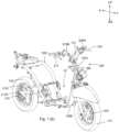
Fig. 1 (a) illustrates a left side view of an exemplary two-wheeled motor vehicle, in accordance with an embodiment of the present subject matter. -
Fig. 1 (b) illustrates a frame assembly of the vehicle provided with selected vehicular parts, in accordance with the embodiment depicted inFig. 1 (a) . -
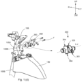
Fig. 1 (c) depicts an enlarged view of the frame assembly of the vehicle, in accordance with the embodiment depicted inFig. 1 (b) . -
Fig. 1 (d) depicts an exploded view of the pressure control device of the braking system employed on the vehicle, in accordance with the embodiment depicted inFig. 1 (b) . -
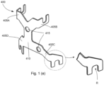
Fig. 1 (e) depicts an isometric view of an orientation bracket, in accordance with the embodiment ofFig. 1 (b) . -
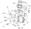
Fig. 1 (f) depicts an exploded view of the pressure control device and assembly thereof, in accordance with the embodiment depicted inFig. 1 (c) . - Conventionally, two-wheeled vehicles or the like are provided with a braking system for slowing or stopping the vehicle. The braking system, usually, includes at least one brake assembly, such as a front wheel brake assembly and a rear wheel brake assembly for a front wheel and a rear wheel, respectively. Such brake assemblies may include, but are not limited to a cam lever, a cam pin, and a pair of friction pads or other means of actuation of the friction pads. Further, each of the front wheel brake assembly and the rear wheel brake assembly is connected to a brake lever for actuation. For example, the brake lever may be coupled to a pair of friction pads for applying friction to each wheel of the two-wheeled vehicle, as and when required. The brake lever can be connected to the brake assembly in a variety of ways. For example, the brake lever can be connected to the brake assembly by means of a cable. In such a case, one end of the cable may be secured to the brake assembly, and the other end of the cable may be secured to the brake lever. Consequently, actuation of the brake lever may result in actuation of the brake assembly and subsequently, the brake may be applied. Nevertheless, the brake assembly can be connected to the lever by means of hydraulic system. Also, in some applications, combination of the cable and the hydraulic means is used.
- Generally, the front wheel and the rear wheel are provided with separate braking systems. Conventional two-wheeler braking systems usually either include hand-operated brakes for both the wheels or include a combination of hand-operated and foot-operated brakes. In the latter case, generally, the front wheel brakes are hand-operated, and include a front wheel brake lever mounted on a handle of the two-wheeled vehicle for actuation, whereas the rear wheel brakes can be foot-operated by a rear wheel brake lever provided near a footrest of the rider. However for saddle type scooters, both brakes may be actuated by hand operated brake levers.
- During operation of the brakes, usually, riders apply the rear wheel brake alone. Such a practice stems from the fact that actuating both the brake levers at the same time may be inconvenient for the rider. In addition, when the front wheel brake is applied weight transfer towards the front wheel cause the front wheel to brake abruptly, and may result in a sudden jerk to the vehicle. The sudden jerk may affect the ride quality and may disturb the balance and stability of the vehicle leading to an accident. However, on the other hand, the braking force applied for application of braking force to the rear wheel may have to be limited, to prevent skidding of the vehicle. As a result, the deceleration experienced by the vehicle may also be limited and subsequently, the stopping distance of the vehicle may be significantly large.
- Conventionally, in order to address the above-mentioned concerns, braking systems that allow simultaneous actuation of a front brake and a rear brake by application of a single brake lever have been developed. Such braking system is capable of uniting the braking operation of both the front wheel brake and the rear wheel brake with the help of a single brake lever, for example the rear wheel brake lever. Accordingly, upon actuation of the single brake lever, such a braking system may allow distribution of braking force to the front wheel as well as the rear wheel of the vehicle. Therefore, the front wheel brake and the rear wheel brake can be simultaneously applied by actuating one brake lever, for example, the rear wheel brake lever. In addition to being convenient for the rider, such braking systems may ensure that the deceleration of the vehicle can be increased and subsequently, the stopping distance may be reduced. Further, as would be understood, in two-wheeled vehicles with such braking systems, a front wheel brake lever may also be provided to independently operate the front wheel brake. Such systems having front and rear brake system actuated in a coordinated manner termed as synchronized braking system.
- Generally, the motor vehicles like two-wheeled vehicles are provided with disc brake for certain application or to improve safety. The disc brake is provided on the front wheel and may be installed on the rear wheel. The disc brake is actuated through hydraulic means. Therefore, a pressure control device is used in order to distribute the pressure or force by a pre-determined pressure or at a predeterminate ratio to the front wheel brake and the rear wheel brake. The pressure control device is to be securely mounted to the vehicle for optimum functioning of the braking system, which is an essential safety system of the vehicle. However, presence of various vehicle systems, moving parts complicates the mounting of the pressure control device. Also, the pressure control device is provided hydraulic connectors and the orientation, angle of such connectors is essential during assembly as it heavily impacts the brake hose routing in the vehicle layout. Conventionally, anti-rotation members are provided in casting of the pressure control device. However, such pressure control device limits the flexibility of use various vehicle layouts. Additionally, the routing of the hose in case of disc brake and routing of cables in case of drum brakes, their length determines the performance of the brake system. Longer hose or cable length tend to lead to spongy feel of the brake system and leads to low durability owing to friction losses. Thus it is important to have an optimum location for the pressure control device without compromising the performance and durability of the system. There is a need to locate the device on the sprung mass of the vehicle & at the same time securely located in case of minor accidental fall of the vehicle. Additionally, it is required to locate the device at optimum distance from majority of the components of the vehicle as well as substantially away from the engine induced vibrations to minimize disturbances.
- Moreover, in a two-wheeled with a step-through type layout, which is commonly called as 'scooter', further complicates implementation of the synchronized braking system. The scooter has a step-through space and also provides a utility box. This reduces the available space on the vehicle for mounting the vehicle parts. The power unit and other components including air induction system, exhaust system, etc. are tightly packaged in the vehicle. The pressure control device, which an essential element of the synchronized braking system of vehicles with front and rear disc brakes is to be securely mounted to the vehicle. The pressure control device is one of biggest parts of the synchronized braking system, which requires substantial amount space. Moreover, hydraulic tubing/piping with the associated pressure control device require ample amount of space and also require longer hoses thereby increasing cost of the system. Also, the piping is made of an elastic material, which is prone to fail upon reciprocating movement of the suspension, especially at the joining portions of the hydraulic piping to the pressure control device. Failure of the pressure control device results in drastic safety related issues as the braking system is an essential safety system.
- Document such as
EP2565090A1 is aimed at addressing problem related to deflection of brake hoses when they are apart from a head pipe, in case of ABS module disposed in vicinity of a head pipe. This document teaches an ABS module mounted forward of the head pipe and offset to one side with respect to a lateral center of the vehicle. Coupling members positioned offset to other side with respect to the lateral center and arranged at mid-section of corresponding piping. - Moreover, another document such as
EP2540587A1 is aimed at addressing problem related to larger space requirement for longer length hydraulic pipes extending between brake controller and ABS modulator, when an ABS modulator and delay valve are disposed in a center in a longitudinal direction of vehicle. This document teaches an ABS modulator arranged in front of a head pipe and the delay valve disposed by side of the ABS modulator - Therefore, the pressure control device is to be mounted to vehicle and at the same time without affecting the functionality, as it is an essential element of the braking system. In addition, the pressure control device is to be securely mounted in the tightly packed vehicle layout, without modifying the layout of the vehicle.
- Thus, it is an object of the present invention to address the aforementioned and other problems stated above.
- Hence, the present invention provides a motor vehicle provided with a synchronized braking system. The synchronized braking system includes a pressure control device functionally connected to at least one brake lever adapted to synchronously actuate the rear wheel brake and the front wheel brake. The pressure control device is disposed in proximity to a head tube of frame assembly of the vehicle.
- It is a feature of the present invention that the pressure control device disposed in proximity to the head tube is a mechanically or electromechanically operated to provide braking force to the front wheel brake and the rear wheel brake upon actuation of the at least one brake lever, which acts a synchronous brake lever that is a rear brake lever. In other words, the pressure control device of the synchronized braking system enables actuation at least two brakes installed on different wheels by the operation of a single control, which is the synchronous brake lever. Moreover, the front lever is capable of independently actuating only the front brake lever.
- At least one brake lever is mounted to a handle bar assembly that is rotatable about a head tube of the frame assembly. In an embodiment, both the front brake lever and the rear brake lever are mounted to the handle bar assembly. The handle bar assembly is connected to the front wheel through suspension(s) and rotatable about the head tube through a steering tube. The front wheel brake is installed on at least one front wheel. The pressure control device is mounted to the head tube, which is in proximity to the handle bar assembly and the front wheel brake thereby reducing the piping length. It is a feature of the present invention that the friction losses, due to the flow of fluid, are reduced due to the reduced piping lengths. In a motorcycle type of vehicle, one brake lever is mounted to the handle bar assembly that is hand operated and other brake lever, which is synchronous brake lever, is mounted near the rider foot to enable foot operation.
- The pressure control device is disposed in proximity to the head tube of the frame assembly, and the pressure control device is at least approximately equidistant from at least one brake lever mounted to a handle bar assembly rotatably supported by the head tube and in proximity to said front wheel brake. Therefore, the pressure control device at least approximately equidistant from at least one brake lever mounted to the handle bar assembly and from the front wheel brake, whereby the pressure control device is in proximity to the brake lever(s) mounted to handle bar assembly and in proximity to the front wheel brake thereby providing optimum and short routing lengths for hose(s).
- A first input hose connecting a synchronous brake lever to the pressure control device, a second input hose connecting a front brake lever to the pressure control device, and a second output hose connecting the pressure control device to the front wheel brake, wherein ratio of length of hose with maximum length to the length of another hose with minimum length being in the range of 0.8 to 1.2 whereby the vehicle with the pressure control device provides optimum hose length.
- In an embodiment, the front brake lever is connected to the pressure control device. Therefore, the front wheel brake is also actuated through the pressure control device.
- The present invention provides a pressure control device assembly capable of supporting the pressure control device, which is capable of actuating the front wheel brake independently, irrespective of the size of the pressure control device. It is one more advantage that the vehicle layout is retained in spite of mounting aforementioned pressure control device.
- The pressure control device is mounted to the head tube, which is substantially at lateral center of the vehicle thereby retaining the weight distribution of the vehicle. Further aspect being, the motor vehicle provides the flexibility to bring the center of the vehicle to vehicle lateral center by disposing the pressure control device at an offset to counter-balance the center of gravity.
- The present invention provides the flexibility for the pressure control device disposed in proximity to the head tube is positioned substantially at along a lateral centre of the vehicle. This enables in maintaining a centre of gravity of the vehicle in lateral direction as a centre of gravity of the pressure control device and a centre of gravity of the vehicle are provided in line providing lateral balance.
- The present invention enables the pressure control device to be disposed at a lateral offset from a lateral centre of the vehicle and in proximity to the head tube whereby the pressure control device balances a centre of the gravity of the vehicle. The direction of offset of the pressure control device is substantially opposite to the lateral direction of the vehicle at which the centre of gravity shift when the pressure control device is not present.
- Further, the pressure control device disposed in proximity to the head tube is substantially in away from the power unit which is one of heavy parts of the vehicle thereby providing balance of weight or centre of gravity in the longitudinal direction of the vehicle.
- The pressure control device of the present subject matter is capable of being retrofitted to the head tube of the frame assembly.
- The pressure control device of the present subject matter is securely disposed away from the power unit of the vehicle that is prone to vibrations that could otherwise affect the function of the pressure control device. Thus, the reliable operation of the system is improved.
- The pressure control device is disposed in proximity to the head tube and is supported by at least one of the head tube or the main tube. It is an advantage that the pressure control device is securely and rigidly mounted to the structural member of the vehicle.
- It is an aspect that the length of the connecting pipes is/are provided with optimum length to accommodate the rotation motion of the handle bar assembly and to accommodate the reciprocating motion of the suspension. In an embodiment, the synchronized braking system is provided with both flexible and rigid pipes, wherein rigid pipes are disposed at non-moving part portion(s) of the vehicle.
- The connecting pipes are provided with intermediate connectors that connect hoses to the pressure control device. The intermediate joints includes banjo joints are connected to the ports of the pressure control device.
- The present invention provides an orientation bracket that is abuttingly disposed adjacent to the pressure control device, wherein the orientation bracket is provided with plurality of arm members that are provided with receiving portions to enable correct/fool proof fitment mounting of the intermediate joints to the respective ports. It is advantageous that the failure due to wrong connections is eliminated.
- The orientation member supports intermediate connectors to have a specific orientation whereby the hose being connected to the intermediate connector is also retained in desired orientation.
- The orientation bracket being independent of the pressure control valve enables use of different orientation bracket with different vehicle layout to suit the hose routing for respective vehicle.
- The pressure control device is securely mounted to the frame assembly in proximity to the head tube with a long axis of the pressure control device disposed in at least one orientation with the long axis disposed along an axis parallel to the lateral direction or longitudinal direction of the vehicle. The present invention provides flexibility in mounting the pressure control device in any desired orientation including at an inclination with respect to the longitudinal axis of the vehicle.
- The pressure control device includes at least one input port disposed in a downward direction to enable smooth curved routing of one or more hoses connecting the at least one brake lever mounted to the handle bar assembly to the pressure control device. This further enables the hoses to be connected with larger radius curvature with reduced flow resistance thereby by providing desired braking performance.
- The pressure control device includes at least one output port disposed in an upward direction to enable optimum routing of the one or more output hoses to at least one of the front wheel brake and the rear wheel brake.
- The pressure control device includes at least one input port disposed in upward direction in proximity to the at least one brake lever mounted to the handle bar assembly thereby providing optimum routing of one or more input hoses when required. Also, at least one output port is disposed in a downward direction in proximity to the front wheel brake thereby providing optimum cable routing when required.
- The pressure control device is mounted in proximity to the handle bar assembly and to the front wheel brake thereby minimizing overall tubing length. It is a further advantage that the cost of the system is reduced.
- The pressure control device is mounted to the front facing side of the head tube is enclosed by a front panel. The pressure control device is mounted to the vehicle by securing it from the external parameters and accidental damage. Moreover, it is yet another advantage that servicing for air bleeding is capable of being performed with minimal parts removal, like removal of the front panel only, thereby improving the serviceability.
- The aspects of the present invention is not limited to two-wheeled vehicle used herein and predominantly includes motor vehicles with a saddle ride-type layout that are similar to the two wheeled vehicles.
- Moreover, the current invention is applicable to a three-wheeled vehicle comprising a front wheel and a pair of rear wheels or vice versa, wherein the three-wheeled vehicle includes a frame assembly with a head tube.
- These and other advantages of the present invention would be described in greater detail in conjunction with the figures in the following description.
-
Fig. 1 (a) illustrates a left side view of anexemplary motor vehicle 100, in accordance with an embodiment of the present invention. Themotor vehicle 100 has aframe assembly 105 having a step-through type layout. Ahandlebar assembly 110 is mounted to a steering shaft (not shown). The steering shaft is rotatably supported by theframe assembly 105 whereby thehandle bar assembly 110 is rotatable about theframe assembly 105 to steer the vehicle. Afront wheel 115 is connected to thehandle bar assembly 110 through one or more front suspension(s) 120. Apower unit 125 is swingably mounted to theframe assembly 105. The power unit includes at least one of an internal combustion engine and a traction motor. Further, thepower unit 125 includes a transmission system (not shown) including an automatic transmission, a continuously variable transmission, or a fixed ratio transmission. - Further, the
power unit 125 is coupled to arear wheel 130 through the transmission system. Also, therear wheel 130 is connected to theframe assembly 105 through one or more rear suspension(s) 135. Aseat assembly 165 is disposed upwardly of thepower unit 125 and is supported by theframe assembly 105. A storage compartment (not shown) is provided below theseat assembly 165 and is also supported by theframe assembly 105. The utility box is accessible in an open condition of theseat assembly 165. - Furthermore, the
vehicle 100 is provided with plurality ofpanels frame assembly 105 and covering the vehicle parts. Especially, afront panel 140A is disposed forward to thehead tube 105A. In the present embodiment, the vehicle includes afloorboard 145 disposed at a step-through space ST defined by theframe assembly 105. The user operates the vehicle by resting feet on thefloorboard 145, in a seated position. Afront fender 150 is covering at least a portion of thefront wheel 110. In the present embodiment, thefront fender 150 is integrated with afront panel 140A of thevehicle 100. Arear fender 155 covers at least a portion of therear wheel 130. Thefront fender 150 and therear fender 155 prevent splashing of dirt on to the vehicle parts and away from thevehicle 100. A fuel tank (not shown) is supported by theframe assembly 105 and is functionally coupled to thepower unit 125. Thevehicle 100 comprises of plurality of electrical/electronic components including aheadlight 160A, atail light 160B, a battery (not shown), a transistor controlled ignition (TCI) unit (not shown), an alternator (not shown), a starter motor (not shown). -
Fig. 1 (b) illustrates a right side perspective view of the frame assembly of the vehicle employed/provided with vehicle parts, in accordance with the embodiment as depicted inFig. 1 (a) . Theframe assembly 105 includes ahead tube 105A, amain tube 105B extending rearward from thehead tube 105A, and one or morerear tubes 105C extending inclinedly rearward from a rear portion of themain tube 105B. In the depicted embodiment, themain tube 105B extends rearwardly downward from thehead tube 105A defining the step-through space ST. Thevehicle 100 is employed with afront wheel brake 205 and arear wheel brake 210 functionally connected to thefront wheel 115 and therear wheel 130, respectively. In an embodiment, thefront wheel brake 205 is a hydraulically operateddisc brake 205 and therear wheel brake 210 is a hydraulically operateddisc brake 210. However, the vehicle may be employed with hydraulically operated mechanical brakes like a drum brake. - Further, the
vehicle 100 includes asynchronized braking system 200 that is provided with asynchronous brake lever 220 mounted to thehandle bar assembly 110 of thevehicle 100 in the present implementation. Also, a frontwheel brake lever 215 is mounted to thehandle bar assembly 110, which functions as an independent brake lever. In an embodiment, the frontwheel brake lever 215 is provided on a right side of thehandle bar 100 and thesynchronous brake lever 220 is provided on the left side of thehandle bar 100. A rider may actuate thefront brake lever 215 to apply thefront wheel brake 205. Similarly, actuation of thesynchronous brake lever 220 applies both thefront wheel brake 205 and therear wheel brake 210. Thedisc brake 210 is provided with adisc 210D affixed to therear wheel 130 and caliper(s) 210C that are functionally coupled to thedisc 210D and fixed at a swing arm or the like. The caliper is supported by thefront suspension 120 in case of thedisc brake 205 employed on the front wheel. - The
front brake lever 215 is coupled to amaster cylinder 215M, which is connected to the brake caliper(s) of thefront wheel brake 205 through a first input hose 225 (shown inFig. 1 (c) ). Upon operation of thefront brake lever 215, pressure is generated in themaster cylinder 215M that is transferred to the brake calipers (not shown) of thefront wheel brake 205 through thefirst input hose 225. Further, thesynchronous brake lever 220 is coupled to anothermaster cylinder 220M, which is connected to apressure distribution device 300 that is connected to the front brake caliper and therear brake caliper 210C through a front brake-output hose 240 and a rear brake-output hose 235, respectively. The rear brake-output hose is referred to asfirst output hose 235 and the front brake-output hose 240 is referred to assecond output hose 240 for brevity. Thepressure distribution device 300 is a pressure control device. Hereinafter, the terms 'pressure control device' and the 'pressure distribution device' are interchangeably used. Therefore, operation of thesynchronous brake lever 220 generates pressure in themaster cylinder 215M that is transferred to thepressure control device 300. From thepressure control device 300, the pressure is distributed to thefront wheel brake 205 and therear wheel brake 210 at a pre-determined ratio. Also, thepressure distribution device 300 is disposed in proximity to thehead tube 105A of thevehicle 100. In an implementation, thepressure distribution device 300 is disposed adjacently ahead of thehead tube 105A and is secured to thehead tube 105A. -
Fig. 1 (c) depicts an enlarged view of the front portion of thevehicle 100, in accordance with the embodiment depicted inFig. 1 (b) . Thepressure distribution device 300 is affixed to thehead tube 105A and is positioned at the front facing side of thehead tube 105A. In the present embodiment, thepressure distribution device 300 is functionally connected to thefront brake lever 215 and thesynchronous brake lever 220, which is specifically to a frontbrake input port 302 and to a synchronousbrake input port 301 of thepressure control device 300, respectively. Also, thepressure control device 300 includes a frontbrake output port 303 and a rear brake output 304 (the input port(s) 301, 302 and the output port(s) 303, 304 are depicted inFig. 1 (d) ). Operation of thefront brake lever 215 will generate pressure in themaster cylinder 215M, which is functionally coupled to thefront brake lever 215, is transferred to the front brake input port of thepressure control device 300 through thefirst input hose 225. This pressure is transferred to thefront wheel brake 205 through asecond output hose 240 thereby actuating thefront wheel brake 205. Thesecond output hose 240 extends from thepressure control device 300 towards thefront wheel brake 205. Similarly, operation of thesynchronous brake lever 220 results in generation of pressure in themaster cylinder 220M functionally coupled tosynchronous brake lever 220. The pressure from themaster cylinder 220M is transferred to thepressure control device 300 through asecond input hose 230, which is a synchronousbrake input hose 230, connected to thepressure control device 300. Then, the pressure frompressure control device 300 is transferred to both thefront wheel brake 205 and therear wheel brake 210 through thesecond output hose 240 and thefirst output hose 235 connected to the front brake output and the rear brake output, respectively. Thefirst output hose 235 extends rearward from thepressure control device 300 and is supported by at least a portion of themain tube 105B. Further, thefirst output hose 235 comprises arigid hose portion 235R that is provided from themain tube 105B towards afloorboard portion 145 of thevehicle 100. - During operation of the
brake lever master cylinder 215M. The displacement of the piston causes an increase in the pressure of the entire system, forcing fluid through the one or more hoses. During operation of thefront brake lever 215, the increase in pressure is transferred to the front brake input port of thepressure control device 300 through the second input hose. In the present embodiment, the front brake input of thepressure control device 300 communicates directly with the front brake output thereby actuating thefront wheel brake 205. - Similarly, operation of the synchronous brake lever transfers increase in pressure to the synchronous brake input of the
pressure control device 300. This change in pressure is displaces a piston provided in thepressure control device 300 thereby effecting a change in pressure through the front brake output and the rear brake output of thepressure control device 300, thereby actuating both the front wheel brake and rear wheel brake. Therefore, thepressure control device 300 disposed in thefront portion vehicle 100 and in proximity of thehead tube 105A provides optimum routing of the hose(s) to the at least onebrake lever handle bar assembly 110 and to thefront wheel brake 205 being substantially equidistant therebetween. Thepressure control device 300 being at least approximately equidistant frombrake levers 215 & 200 and from thefront wheel brake 205 requiring optimum length of the hose(s) making it cost effective. Also, number of bends required for routing the hose(s) is minimized. - In one embodiment, the front brake system is independent of the synchronous brake system.
- The
pressure control device 300 is connected to thefront brake lever 215, to thesynchronous brake lever 220, thefront wheel brake 205, and therear wheel brake 210 through plurality offlexible hoses handle bar assembly 110 supporting thefront brake lever 215 and therear brake lever 220 is a rotating member and as thepressure control device 300 disposed below thehandle bar assembly 110 is rigidly and securely fixed to theframe assembly 105 without adding any weight on the moving/rotating members like thefront wheel 115 or therear wheel 120. Also, the position of thepressure control device 300 with reference to thefront wheel brake 205 is varying due to the presence offront suspension 120 that compresses and expands with the road conditions. Thus, the one or more hoses are made of flexible material enable avoidance of damage of hoses. In addition, the length of the hose is substantially greater that the distance between the points of connection to accommodate the aforementioned variations. - Provision of the
pressure control device 300 at thehead tube 105A facilitates use of optimum length ofhose 240 for connecting thepressure control device 300 to thefront brake lever 215 and therear brake lever 220. Also, thepressure control device 300 is at optimum distance and between thehandle bar assembly 110 and thefront wheel brake 205 thereby providing optimum hose routing. Further, the plurality of hoses is connected to thepressure control device 300 through intermediate connector(s) 305A, 305B, 305C, 305D (shown inFig. 1 (f) ). -
Fig. 1 (d) depicts an exploded view of thepressure control device 300 of the braking system employed on the vehicle, in accordance with the embodiment depicted inFig. 1 (b) . Theframe assembly 105 is affixed with a mountingmember 105M that is welded to theframe assembly 105. In other embodiment, the mountingmember 105M is affixed to theframe assembly 105. In the present embodiment, the mountingmember 105M is having a U-shaped profile with an opening of the U-shape facing theframe assembly 105. The mountingmember 105M is affixed to the front facing side of thehead tube 105A through the ends of the mountingmember 105M. The U-shaped profile provides clearance between a peripheral surface of thehead tube 105A and the mountingmember 105M thereby enabling ease of assembly of thepressure control device 300 using fasteners. Further, the mountingmember 105M is provided with one or more mounting point(s) for securing thepressure control device 300 to the mountingmember 105M, wherein in one embodiment the mounting point(s) are apertures. Moreover, the mounting point(s) are provided so as to align with one or more mounting point(s) provided on thepressure control device 300, thereby enabling mounting of thepressure control device 300 in a desired orientation. - Further, the
first input hose 225, thesecond input hose 230, and thesecond output hose 240 are provided with lengths with a ratio of maximum length to minimum length being in the range of 0.8 to 1.2 whereby thevehicle 100 with thepressure control device 300 provides optimum hose length. - In the present implementation, the
pressure control device 300 is securely mounted to theframe assembly 105 in proximity to thehead tube 105A in at least one orientation. In the depicted embodiment, the pressure control device is disposed in a first orientation with a long axis L-L' thereof is substantially parallel to a lateral direction RH-LH of thevehicle 100. Thepressure control device 300 includes at least oneinput port input hoses brake lever pressure control device 300. Thepressure control device 300 includes at least oneoutput port more hoses front wheel brake 205 and therear wheel brake 210. - The pressure control device 300is disposed behind the
front panel 140A and above afront fender 150. Thefront panel 140A is covering at least a portion of thepressure control device 300, and thefront panel 140A is supported by anadditional bracket 106 mounted to thehead tube 105A. Theadditional bracket 106 is extending in forward direction F beyond a forward most portion of thepressure control device 300. Also, thefront panel 140A in removed condition provides access to thepressure control device 300 and also hoses connected thereto. - The
pressure control device 300 is disposed in a second orientation with the long axis L-L' thereof disposed substantially parallel to the longitudinal direction F-R of thevehicle 100. Therefore,head tube 105A supports an auxiliary power source (not shown) or electrical components like horn or head lamp in the front facing side ofhead tube 105A and thepressure control device 300 is disposed towards one lateral side RH or LH of theframe assembly 105 and in proximity to thehead tube 105A to provide optimum routing of the hose(s). - Furthermore, an
orientation bracket 400 is provided that abuts against thepressure control device 300. One or more fasteners F are used to secure theorientation bracket 400 and thepressure control device 300 to the mountingmember 105M. Theorientation bracket 400 is alternatively referred to as a poka-yoke bracket 400 herein. However, in another embodiment, the poka-yoke bracket 400 is secured to thepressure control device 300 by snap-fit, a clip-on type fit, or any known securing means. - In the present implementation, the intermediate connector(s) are banjo joint(s) that comprises of a perforated hollow bolt and spherical union for fluid transfer. Through the hollow bolt the hose is secured to the at least one of the input(s) and output(s) of the
pressure control device 300. However, there is a possibility of wrong assembly due to the use of plurality of hoses and their respective banjo joint. Thus, a poka-yoke bracket 400 is provided that is secured to thepressure control device 300. The poka-yoke bracket 400 works in conjunction with banjo joints.Fig. 1 (e) depicts an isometric view of the poka-yoke bracket 400, in accordance with the present embodiment. - The poka-
yoke bracket 400 includes plurality ofarm members arm members pressure control device 300. In the depicted embodiment, the poka-yoke bracket 400 is provided with fourarm members base portion 410 is provided with mountingpoints 415 that align with the mounting points provided on thepressure control device 300 and the mountingmember 105M. Each arm member of the poka-yoke bracket 400 extends towards each of theinput ports output ports pressure control device 300. Also, each of thearm members intermediate connector Fig. 1 (e) ) that are provided with a with a specific orientation. Therefore, thearm members intermediate connectors pressure control device 300. Hence, correct mounting of the banjo joints is achieved thereby eliminating functional failure due to wrong assembly thereby providing easy and fool proof assembly. -
Fig. 1 (f) depicts an exploded view of thepressure control device 300 assembly, in accordance with the embodiment depicted inFig. 1 (c) . In the present embodiment, fourbanjo joints hoses pressure control device 300 is provided with a frontbrake input port 301 and a synchronousbrake input port 302 positioned on a downward portion of thepressure control device 300. Similarly, a frontbrake output port 303 and a rearbrake output port 304 are provided in the upward direction/portion UP of thepressure control device 300. A first banjo joint 305A connects thesynchronous brake lever 220 to thepressure control device 300, and a second banjo joint 305B connects thefront brake lever 215 to thepressure control device 300. Further, the input ports are provided on opposite sides to the position the brake levers are disposed to provide a smooth and large curvature. Similarly, a third banjo joint 305C and a fourth banjo joint 305D connect therear wheel brake 210 and thefront wheel brake 205 to thepressure control device 300, respectively. Moreover, the banjo joints 305A, 305B, 305C, 305D enable ease of assembly of the connection without affecting thehoses pressure control device 300 disposed in proximity to thehead tube 105A provides flexibility to change the position of the ports depending on the vehicle layout requirements. - The
arm members Fig. 1 (e) ) of the poka-yoke bracket 400 extend towards the aforementioned port(s), and only one banjo joint of the plurality of banjo joints abuts against the receiving portion(s) R of the banjo joint(s) 305A, 305B, 305C, and 305D. Moreover, this enables use of samepressure control device 300 in a different vehicle layout by merely changing the poka-yoke bracket 400 in accordance to the desired layout. Also, the fasteners F1, F2 securely hold thepressure control device 300 and the poka-yoke bracket 400 to the mountingmember 105M. - Also, provision of the
orientation bracket 400 independent of thepressure control device 300 enables use of the samepressure control device 300 for different vehicle layouts with mere modification of theorientation bracket 400 according to thepressure control device 300 orientation.
Claims (14)
- A two-wheeled motor vehicle (100) comprising a synchronized braking system (200), said vehicle (100) comprising:a frame assembly (105) comprising a head tube (105 A) disposed in a front portion thereof;a front wheel brake (205) capable of applying braking forces to at least one front wheel (115), said at least one front wheel (115) rotatable about said head tube (105 A) to enable steering of said vehicle (100);a rear wheel brake (210) capable of applying braking forces to at least one rear wheel (130);a pressure control device (300) of said synchronized braking system (200) is functionally connected to said rear wheel brake (210) through a first output hose (235) and is functionally connected to said front wheel brake (205) through a second output hose (240), said pressure control device (300) capable of being actuated by a synchronous brake lever (220), said pressure control device (300) is securely disposed in proximity to said head tube (105A) of the frame assembly (105); characterised byan orientation bracket (400) disposed adjacent to said pressure control device (300) and is adapted to work with said pressure control device (300) to enable fool proof fitment of one or more intermediate connector/s (305A, 305B, 305C, 305D) connecting one or more hose/s (225, 230, 235, 240) to said pressure control device (300), wherein
said orientation bracket (400) includes one or more arm members (405A, 405B, 405C, 405D) and each of the one or more arm members (405 A, 405B, 405C, 405D) includes a receiving portion (R) capable of receiving only specific intermediate connector of said one or more intermediate conector/s (305 A, 305B, 305C, 305D) thereby enabling said fool proof fitment and said arm member (405 A, 405B, 405C, 405D) retains the intermediate connectors (405 A, 405B, 405C, 405D) in a specific orientation thereby retaining a desired orientation of the one or more hoses (225, 230, 235, 240). - The two-wheeled motor vehicle (100) as claimed in claim 1, wherein said pressure control device (300) is substantially equidistant from at least one brake lever (215, 220) mounted to a handle bar assembly (110) rotatable about said head tube (105A) and from said front wheel brake (205).
- The two-wheeled motor vehicle (100) as claimed in claim 1, wherein said pressure control device (300) is securely disposed ahead of said head tube (105 A), and said pressure control device (300) is having a long axis (L-L') disposed substantially in a first orientation being parallel to a lateral direction (RH-LH) of said motor vehicle (100).
- The two-wheeled motor vehicle (100) as claimed in claim 1, wherein said pressure control device (300) is securely disposed towards one lateral side (RH, LH) of said head tube (105A), and said pressure control device (300) is having a long axis (L-LD) disposed in a second orientation being parallel to a longitudinal direction (F-R) of said motor vehicle (100).
- The two-wheeled motor vehicle (100) as claimed in claim 1, 3 or 4, wherein said pressure control device (300) is securely mounted to said frame assembly (105) in proximity to said head tube (105A) in at least one of said first orientation or said second orientation, and said pressure control device (300) includes at least one input port (301, 302) disposed in a downward direction (DW) to enable curved routing of one or more input hoses (225, 230) connecting said at least one brake lever (215, 220) thereto and said pressure control device (300) includes at least one output port (303, 304) disposed in an upward (UP) direction to enable routing of said one or more output hoses (235, 240) to at least one of said front wheel brake (205) and said rear wheel brake (210).
- The two-wheeled motor vehicle (100) as claimed in claim 1, 3 or 4, wherein said pressure control device (300) is securely mounted to said frame assembly (105) in proximity to said head tube (105A) in at least one of said first orientation and said second orientation, and said pressure control device (300) includes at least one input port (301, 302) disposed in an downward direction (DW) and includes at least one output port (303, 304) disposed in a upward direction (UP).
- The two-wheeled motor vehicle (100) as claimed in claim 1 or 3, wherein said pressure control device (300) is mounted to a front facing side of head tube (105 A) and is disposed below said handle bar assembly (110) and is above said front wheel brake (120) therebetween, whereby said pressure control device (300) is substantially equidistant to said synchronous brake lever (220) mounted to said handle bar assembly (110) and to said front wheel brake (205).
- The two-wheeled motor vehicle (100) as claimed in claim 1, wherein said pressure control device (300) is affixed to a mounting member (105M) secured to said frame assembly (105), said mounting member (105M) is having a U-shaped profile with clearance to enables fastening of said pressure control device (300), and said mounting member (105M) includes one or more mounting point(s) provided to align with one or more mounting point(s) provided on the pressure control device (300) thereby enabling mounting of the pressure control device (300) in a desired orientation.
- The two-wheeled motor vehicle (100) as claimed in claim 1, wherein said pressure control device (300) is disposed substantially at along a lateral centre of the vehicle (100) whereby a centre of gravity of the pressure control device (300) and a centre of gravity of the vehicle (100) are in line providing balance in a lateral direction (RH-LH).
- The two-wheeled motor vehicle (100) as claimed in claim 1, wherein said pressure control device (300) is disposed at a lateral offset from a lateral centre of the vehicle (100) whereby the pressure control device (300) balances a centre of the gravity of the vehicle (100).
- The two-wheeled motor vehicle (100) as claimed in claim 1, wherein said pressure control device (300) is connected to one brake lever ( 220) and other brake lever (215) through a first input hose (225) and a second input hose (230), respectively, and said pressure control device (300) is connected to said front wheel brake (205) through a second hose (240), and wherein said a ratio of maximum length to minimum length between the first input hose (255), the second input hose (230), and the second output hose (240) being in the range of 0.8 to 1.2.
- The two-wheeled motor vehicle (100) as claimed in claim 1, wherein said pressure control device (300) is disposed behind a front panel (140A) and above a front fender (150), said front panel (140A) is covering at least a portion of the pressure control device (300), and said front panel (140A) is supported by an additional bracket (106) mounted to said head tube (105A) extending in forward direction (F) beyond a forward most portion of said pressure control device (300).
- The two-wheeled vehicle (100) as claimed in claim 1, wherein said pressure control device (300) is connected to a front brake lever (215) for application of braking force independently to the front wheel brake (205) and said front brake lever (215) is mounted to said handle bar assembly (110) of said vehicle (100).
- An orientation bracket (400) adapted to work with a pressure control device (300) of a synchronized braking system (200) for a two-wheeled motor vehicle (100) according to any one of claims 1 to 13, said orientation bracket (400) comprising:- a base portion (410); and- one or more arm members (405A, 405B, 405C, 405D) supported by said base portion (410),wherein
said one or more arm members (405 A, 405B, 405C, 405D) is/are configured to extend towards one or more input port/s (301, 302) and towards one or more output port/s (303, 304) of said pressure control device (300), and each of said one or more arm members (405A, 405B, 405C, 405D) includes a receiving portion (R) capable of receiving only a one or more specific intermediate connector (305A, 305B, 305C, 305D) connecting one or more hose/s (224, 230, 235, 240) to said pressure control device (300) thereof.
Applications Claiming Priority (2)
| Application Number | Priority Date | Filing Date | Title |
|---|---|---|---|
| IN201641040199 | 2016-11-24 | ||
| PCT/IB2017/057378 WO2018096493A1 (en) | 2016-11-24 | 2017-11-24 | A two-wheeled vehicle with synchronized braking system |
Publications (4)
| Publication Number | Publication Date |
|---|---|
| EP3544883A1 EP3544883A1 (en) | 2019-10-02 |
| EP3544883A4 EP3544883A4 (en) | 2020-11-25 |
| EP3544883B1 true EP3544883B1 (en) | 2025-04-16 |
| EP3544883C0 EP3544883C0 (en) | 2025-04-16 |
Family
ID=62195780
Family Applications (1)
| Application Number | Title | Priority Date | Filing Date |
|---|---|---|---|
| EP17874792.9A Active EP3544883B1 (en) | 2016-11-24 | 2017-11-24 | A two-wheeled vehicle with synchronized braking system |
Country Status (3)
| Country | Link |
|---|---|
| EP (1) | EP3544883B1 (en) |
| CN (1) | CN110035948B (en) |
| WO (1) | WO2018096493A1 (en) |
Families Citing this family (2)
| Publication number | Priority date | Publication date | Assignee | Title |
|---|---|---|---|---|
| WO2020105067A1 (en) | 2018-11-19 | 2020-05-28 | Tvs Motor Company Limited | A motor vehicle and a support memer for a brake unit thereof |
| EP4100303B1 (en) * | 2020-02-04 | 2024-02-28 | Indian Motorcycle International, LLC | Motorcycle |
Family Cites Families (8)
| Publication number | Priority date | Publication date | Assignee | Title |
|---|---|---|---|---|
| JP2003261086A (en) * | 2002-03-07 | 2003-09-16 | Shimano Inc | Brake operating device for bicycle |
| WO2009050961A1 (en) * | 2007-10-18 | 2009-04-23 | Bosch Corporation | Brake liquid pressure controller |
| CN201124920Y (en) * | 2007-11-21 | 2008-10-01 | 南京金城机械有限公司 | Hydraulic associated braking system for motorcycle |
| JP5227872B2 (en) * | 2008-08-29 | 2013-07-03 | 本田技研工業株式会社 | Interlocking brake device for vehicles |
| JP5627112B2 (en) | 2011-07-01 | 2014-11-19 | 本田技研工業株式会社 | Motorcycle |
| JP5751989B2 (en) | 2011-08-27 | 2015-07-22 | 本田技研工業株式会社 | Motorcycle |
| TW201313541A (en) * | 2011-09-23 | 2013-04-01 | Well Child Technology Co | Safety brake |
| WO2016113756A1 (en) * | 2015-01-14 | 2016-07-21 | Tvs Motor Company Limited | Synchronized braking system for two-wheeled vehicles |
-
2017
- 2017-11-24 WO PCT/IB2017/057378 patent/WO2018096493A1/en not_active Ceased
- 2017-11-24 EP EP17874792.9A patent/EP3544883B1/en active Active
- 2017-11-24 CN CN201780072452.2A patent/CN110035948B/en active Active
Also Published As
| Publication number | Publication date |
|---|---|
| WO2018096493A1 (en) | 2018-05-31 |
| BR112019010529A2 (en) | 2019-09-17 |
| CN110035948A (en) | 2019-07-19 |
| EP3544883A1 (en) | 2019-10-02 |
| EP3544883C0 (en) | 2025-04-16 |
| EP3544883A4 (en) | 2020-11-25 |
| CN110035948B (en) | 2021-07-06 |
Similar Documents
| Publication | Publication Date | Title |
|---|---|---|
| US6450301B1 (en) | Brake device | |
| US8651213B2 (en) | Brake device for saddled vehicle | |
| EP2604498B1 (en) | Motorcycle brake pipe structure | |
| CN105722753B (en) | motorcycle | |
| JP5627112B2 (en) | Motorcycle | |
| US7708098B2 (en) | Brake support structure | |
| JP5871382B2 (en) | Harness arrangement structure for saddle riding type vehicles | |
| EP0995653A2 (en) | Brake device for vehicle having barhandle | |
| WO2018123091A1 (en) | Straddle-type vehicle | |
| EP3544883B1 (en) | A two-wheeled vehicle with synchronized braking system | |
| US7621566B2 (en) | Brake hose support structure | |
| EP3715234B1 (en) | Saddle-type vehicle | |
| JP2019081518A (en) | Saddle riding type vehicle | |
| WO2018154428A1 (en) | Foot operated synchronized braking system | |
| JP6904999B2 (en) | Saddle-type vehicle | |
| JP2018177201A (en) | Saddle type vehicle | |
| JP2019098864A (en) | Brake piping structure for saddled vehicle | |
| EP3388322B1 (en) | Straddled vehicle | |
| WO2018109705A1 (en) | Synchronous brake actuation assembly for a two-wheeler | |
| EP4180309A1 (en) | A saddle type vehicle | |
| US20200255083A1 (en) | Brake piping structure for saddled vehicles | |
| BR112019010529B1 (en) | TWO-WHEEL VEHICLE WITH SYNCHRONIZED BRAKING SYSTEM | |
| JP2018140761A (en) | Saddle-riding type vehicle | |
| WO2020194335A1 (en) | A synchronized braking system for a vehicle | |
| WO2020202198A1 (en) | Multi-purpose swing arm of vehicle |
Legal Events
| Date | Code | Title | Description |
|---|---|---|---|
| STAA | Information on the status of an ep patent application or granted ep patent |
Free format text: STATUS: THE INTERNATIONAL PUBLICATION HAS BEEN MADE |
|
| PUAI | Public reference made under article 153(3) epc to a published international application that has entered the european phase |
Free format text: ORIGINAL CODE: 0009012 |
|
| STAA | Information on the status of an ep patent application or granted ep patent |
Free format text: STATUS: REQUEST FOR EXAMINATION WAS MADE |
|
| 17P | Request for examination filed |
Effective date: 20190514 |
|
| AK | Designated contracting states |
Kind code of ref document: A1 Designated state(s): AL AT BE BG CH CY CZ DE DK EE ES FI FR GB GR HR HU IE IS IT LI LT LU LV MC MK MT NL NO PL PT RO RS SE SI SK SM TR |
|
| AX | Request for extension of the european patent |
Extension state: BA ME |
|
| DAV | Request for validation of the european patent (deleted) | ||
| DAX | Request for extension of the european patent (deleted) | ||
| A4 | Supplementary search report drawn up and despatched |
Effective date: 20201023 |
|
| RIC1 | Information provided on ipc code assigned before grant |
Ipc: F16L 27/093 20060101ALI20201019BHEP Ipc: B60T 1/08 20060101ALI20201019BHEP Ipc: B60T 8/26 20060101ALI20201019BHEP Ipc: B62L 3/02 20060101ALI20201019BHEP Ipc: B62L 3/08 20060101AFI20201019BHEP Ipc: F16L 41/04 20060101ALI20201019BHEP |
|
| STAA | Information on the status of an ep patent application or granted ep patent |
Free format text: STATUS: EXAMINATION IS IN PROGRESS |
|
| 17Q | First examination report despatched |
Effective date: 20221021 |
|
| GRAP | Despatch of communication of intention to grant a patent |
Free format text: ORIGINAL CODE: EPIDOSNIGR1 |
|
| STAA | Information on the status of an ep patent application or granted ep patent |
Free format text: STATUS: GRANT OF PATENT IS INTENDED |
|
| INTG | Intention to grant announced |
Effective date: 20241108 |
|
| GRAS | Grant fee paid |
Free format text: ORIGINAL CODE: EPIDOSNIGR3 |
|
| GRAA | (expected) grant |
Free format text: ORIGINAL CODE: 0009210 |
|
| STAA | Information on the status of an ep patent application or granted ep patent |
Free format text: STATUS: THE PATENT HAS BEEN GRANTED |
|
| AK | Designated contracting states |
Kind code of ref document: B1 Designated state(s): AL AT BE BG CH CY CZ DE DK EE ES FI FR GB GR HR HU IE IS IT LI LT LU LV MC MK MT NL NO PL PT RO RS SE SI SK SM TR |
|
| REG | Reference to a national code |
Ref country code: GB Ref legal event code: FG4D |
|
| REG | Reference to a national code |
Ref country code: CH Ref legal event code: EP |
|
| REG | Reference to a national code |
Ref country code: IE Ref legal event code: FG4D |
|
| REG | Reference to a national code |
Ref country code: DE Ref legal event code: R096 Ref document number: 602017088993 Country of ref document: DE |
|
| U01 | Request for unitary effect filed |
Effective date: 20250514 |
|
| U07 | Unitary effect registered |
Designated state(s): AT BE BG DE DK EE FI FR IT LT LU LV MT NL PT RO SE SI Effective date: 20250520 |
|
| PG25 | Lapsed in a contracting state [announced via postgrant information from national office to epo] |
Ref country code: ES Free format text: LAPSE BECAUSE OF FAILURE TO SUBMIT A TRANSLATION OF THE DESCRIPTION OR TO PAY THE FEE WITHIN THE PRESCRIBED TIME-LIMIT Effective date: 20250416 |
|
| PG25 | Lapsed in a contracting state [announced via postgrant information from national office to epo] |
Ref country code: NO Free format text: LAPSE BECAUSE OF FAILURE TO SUBMIT A TRANSLATION OF THE DESCRIPTION OR TO PAY THE FEE WITHIN THE PRESCRIBED TIME-LIMIT Effective date: 20250716 Ref country code: GR Free format text: LAPSE BECAUSE OF FAILURE TO SUBMIT A TRANSLATION OF THE DESCRIPTION OR TO PAY THE FEE WITHIN THE PRESCRIBED TIME-LIMIT Effective date: 20250717 |
|
| PG25 | Lapsed in a contracting state [announced via postgrant information from national office to epo] |
Ref country code: PL Free format text: LAPSE BECAUSE OF FAILURE TO SUBMIT A TRANSLATION OF THE DESCRIPTION OR TO PAY THE FEE WITHIN THE PRESCRIBED TIME-LIMIT Effective date: 20250416 |
|
| PG25 | Lapsed in a contracting state [announced via postgrant information from national office to epo] |
Ref country code: HR Free format text: LAPSE BECAUSE OF FAILURE TO SUBMIT A TRANSLATION OF THE DESCRIPTION OR TO PAY THE FEE WITHIN THE PRESCRIBED TIME-LIMIT Effective date: 20250416 |
|
| PG25 | Lapsed in a contracting state [announced via postgrant information from national office to epo] |
Ref country code: RS Free format text: LAPSE BECAUSE OF FAILURE TO SUBMIT A TRANSLATION OF THE DESCRIPTION OR TO PAY THE FEE WITHIN THE PRESCRIBED TIME-LIMIT Effective date: 20250716 |
|
| PG25 | Lapsed in a contracting state [announced via postgrant information from national office to epo] |
Ref country code: IS Free format text: LAPSE BECAUSE OF FAILURE TO SUBMIT A TRANSLATION OF THE DESCRIPTION OR TO PAY THE FEE WITHIN THE PRESCRIBED TIME-LIMIT Effective date: 20250816 |
|
| U20 | Renewal fee for the european patent with unitary effect paid |
Year of fee payment: 9 Effective date: 20251128 |
|
| PG25 | Lapsed in a contracting state [announced via postgrant information from national office to epo] |
Ref country code: SM Free format text: LAPSE BECAUSE OF FAILURE TO SUBMIT A TRANSLATION OF THE DESCRIPTION OR TO PAY THE FEE WITHIN THE PRESCRIBED TIME-LIMIT Effective date: 20250416 |
|
| PG25 | Lapsed in a contracting state [announced via postgrant information from national office to epo] |
Ref country code: CZ Free format text: LAPSE BECAUSE OF FAILURE TO SUBMIT A TRANSLATION OF THE DESCRIPTION OR TO PAY THE FEE WITHIN THE PRESCRIBED TIME-LIMIT Effective date: 20250416 |
|
| PG25 | Lapsed in a contracting state [announced via postgrant information from national office to epo] |
Ref country code: SK Free format text: LAPSE BECAUSE OF FAILURE TO SUBMIT A TRANSLATION OF THE DESCRIPTION OR TO PAY THE FEE WITHIN THE PRESCRIBED TIME-LIMIT Effective date: 20250416 |
|
| PLBE | No opposition filed within time limit |
Free format text: ORIGINAL CODE: 0009261 |
|
| STAA | Information on the status of an ep patent application or granted ep patent |
Free format text: STATUS: NO OPPOSITION FILED WITHIN TIME LIMIT |
|
| REG | Reference to a national code |
Ref country code: CH Ref legal event code: L10 Free format text: ST27 STATUS EVENT CODE: U-0-0-L10-L00 (AS PROVIDED BY THE NATIONAL OFFICE) Effective date: 20260225 |
|
| 26N | No opposition filed |
Effective date: 20260119 |