EP3544689B1 - Fall arrest device with controlled retraction speed - Google Patents
Fall arrest device with controlled retraction speed Download PDFInfo
- Publication number
- EP3544689B1 EP3544689B1 EP17801767.9A EP17801767A EP3544689B1 EP 3544689 B1 EP3544689 B1 EP 3544689B1 EP 17801767 A EP17801767 A EP 17801767A EP 3544689 B1 EP3544689 B1 EP 3544689B1
- Authority
- EP
- European Patent Office
- Prior art keywords
- drum
- rotatable
- brake
- self
- brake body
- Prior art date
- Legal status (The legal status is an assumption and is not a legal conclusion. Google has not performed a legal analysis and makes no representation as to the accuracy of the status listed.)
- Active
Links
Images



Classifications
-
- A—HUMAN NECESSITIES
- A62—LIFE-SAVING; FIRE-FIGHTING
- A62B—DEVICES, APPARATUS OR METHODS FOR LIFE-SAVING
- A62B1/00—Devices for lowering persons from buildings or the like
- A62B1/06—Devices for lowering persons from buildings or the like by making use of rope-lowering devices
- A62B1/08—Devices for lowering persons from buildings or the like by making use of rope-lowering devices with brake mechanisms for the winches or pulleys
- A62B1/10—Devices for lowering persons from buildings or the like by making use of rope-lowering devices with brake mechanisms for the winches or pulleys mechanically operated
-
- A—HUMAN NECESSITIES
- A62—LIFE-SAVING; FIRE-FIGHTING
- A62B—DEVICES, APPARATUS OR METHODS FOR LIFE-SAVING
- A62B35/00—Safety belts or body harnesses; Similar equipment for limiting displacement of the human body, especially in case of sudden changes of motion
- A62B35/0093—Fall arrest reel devices
-
- A—HUMAN NECESSITIES
- A62—LIFE-SAVING; FIRE-FIGHTING
- A62B—DEVICES, APPARATUS OR METHODS FOR LIFE-SAVING
- A62B35/00—Safety belts or body harnesses; Similar equipment for limiting displacement of the human body, especially in case of sudden changes of motion
- A62B35/04—Safety belts or body harnesses; Similar equipment for limiting displacement of the human body, especially in case of sudden changes of motion incorporating energy absorbing means
Definitions
- the present invention relates generally to a fall arrest system and a fall arrest device, and in particular to a brake arrangement for a fall arrest device, such as a self- retracting lanyard.
- Fall arrest systems are used to prevent personnel working at height from suffering injury as a result of falling or other such events. Fall arrest systems are often referred to as height safety systems or fall prevention systems. Frequently, such systems and devices include a safety block arranged to be suspended overhead from an anchor structure. Such arrangements typically include: a drum upon which a safety line or lifeline is wound; a speed responsive mechanism arranged to inhibit the drum rotation above a predetermined rotational speed; and an energy absorber device arranged to be activated if a load above a predetermined threshold is deployed when the speed responsive mechanism is deployed.
- a self-retracting lanyard (or lifeline) (SRL) is a fall arrest device that includes a rewinding mechanism configured to automatically pay out and retract the lifeline as necessary to allow the user movement while keeping the lifeline taut.
- the drum upon which the lifeline is wound is, therefore, biased to rewind the lifeline onto the drum.
- a corresponding line retraction device is disclosed by the international patent application WO 2016 / 127 946 .
- the international patent application WO 2016 / 120 614 discloses a fall arrest device with a speed sensible engagement mechanism.
- the US patent applications US 2010/308149 A1 and US 2011 / 147 125 A1 disclose fall arrest devices with eddy current brake arrangements.
- the US patent applications US 2010 / 226 748 A1 and US 4 448 284 A disclose line dispensing devices that use friction brake arrangements.
- an improved brake arrangement for a fall arrest system and device and an improved fall arrest system and device.
- the invention is defined by claim 1, whereas the dependent claims 2 to 15 provide advantageous embodiments.
- the present invention provides a fall arrest device comprising: a rotatable drum for winding a lifeline; and a brake arrangement comprising a rotatable brake body arranged to rotate in response to rotation of the drum; wherein rotation of the rotatable brake body applies a braking force to the drum as the lifeline is being retracted onto the drum.
- the rotational axis of the rotatable brake body is spaced from the rotational axis of the drum. Further, according to the invention, the rotatable brake body engages the rotatable drum, such that the rotatable drum drives the rotation of the brake body.
- the rotational axis of the rotatable drum and the rotational axis of the rotatable brake body are aligned in the same direction.
- the rotatable drum is provided with a driver portion which drives the rotation of the rotatable brake body, the driver portion arranged to be rotated by the drum.
- the driver portion is a drive ring which is coaxial with the drum.
- the driver portion is a drive ring having a rotational axis that is coaxial with the rotational axis of the drum.
- the driver portion is the circumferential perimeter of the drum.
- one or both of the driver portion and the rotatable brake body have gear or cog rings that operate to drive the rotatable brake body.
- the brake arrangement is a centrifugal brake arrangement.
- the centrifugal brake arrangement comprises at least one brake shoe slidably and/or float mounted on the rotatable brake body, wherein in response to rotation of the rotatable brake body the at least one brake shoe is configured to slidably move outwards from an inactive position towards an active position, wherein in the active position the at least one brake shoe contacts an abutment surface which slows the rotation of the rotatable brake body.
- the at least one brake shoe is slidably and/or float mounted on a rotatable seat driven by the rotatable brake body.
- the abutment surface is a brake lining.
- the fall arrest device further comprises a re-winding mechanism configured to rewind the lifeline onto the drum.
- the rotatable brake body applies a braking force when the drum rotates in a first direction to rewind the lifeline onto the drum but not when the drum rotates in a second direction to payout the lifeline.
- the brake arrangement comprises a one-way bearing or sprag clutch in communication with the rotatable brake body, such that the rotatable brake body freewheels when the drum rotates in the second direction.
- the drum is mounted on a rotatable shaft
- the device further comprises a speed responsive mechanism arranged to stop the drum or shaft rotation above a predetermined rotational speed.
- the speed responsive mechanism is separate from the brake arrangement.
- the fall arrest device further comprises an energy absorber device arranged to be activated if a load above a predetermined threshold is deployed when the speed responsive mechanism is deployed.
- the speed responsive mechanism comprises: a stop; a pawl carrier arranged to rotate with the drum; and at least one pawl pivotally- mounted on the pawl carrier, wherein each pawl is biased inwards by a pawl biasing member towards an inactive position in which the pawl does not contact the stop, wherein when the drum reaches a threshold rotational speed, the at least one pawl pivots outwards against the force of the pawl biasing member into an active position such that the at least one pawl cannot rotate past the stop.
- the energy absorber device comprises a resilient energy absorber ring.
- the drum can be of any size and the term "drum," for the purposes of definition, may be used interchangeably with spool, reel, and/or other device upon which a safety line can be wound.
- the rotatable brake body engages the rotatable drum.
- a circumferential portion of the rotatable brake body may contact a circumferential portion of the drum.
- the drum may directly drive the rotation of the rotatable brake body.
- the rotatable brake body will rotate in the opposite direction to the drum.
- the amount of the braking force transferred from the rotatable brake body to the drum may depend on the relative sizes of the drum and the rotatable brake body. This is due to the spacing of the rotational axes of the drum and the rotatable brake body. To increase the braking force on the drum, the size of the rotatable brake body relative to the drum may be increased.
- the rotatable brake body may directly engage a surface of the drum.
- the device may comprise an annular member mounted on the drum.
- the rotatable brake body may contact the annular member, which may reduce the risk of the surface of the drum being damaged or worn by the brake arrangement.
- the rotational axis of the rotatable brake body may be aligned in the same direction as the rotational axis of the drum.
- the rotational axes may be parallel.
- the rotatable brake body may be offset from the drum.
- the rotatable drum may be provided with a driver portion which drives the rotation of the rotatable brake body, the driver portion arranged to be rotated by the drum.
- the driver portion may engage the drum, or the annular member mounted on the drum, and the rotatable brake body may engage the driver portion.
- the driver portion may be a drive ring which is coaxial with the drum.
- the driver portion may be mounted on the same rotary shaft as the drum, and/or the driver portion may be connected to the drum.
- the driver portion may be a drive ring having a rotational axis that is spaced from the rotational axis of the drum.
- the driver portion may be positioned between the drum and the rotatable brake body.
- the driver portion may be the circumferential perimeter of the drum.
- the driver portion and the rotatable brake body may have respective gear rings that operate to drive the rotatable brake body.
- the gears may comprise a plurality of teeth.
- the teeth of the driver portion may mesh with the teeth of the rotatable brake body.
- An intermediate gear may be provided intermediate the rotatable brake body and the drum.
- the amount of the braking force transferred from the rotatable brake body to the drum depends, at least in part, on the relative sizes (diameters) of the driver portion and the rotatable brake body.
- the size of the rotatable brake body relative to the driver portion may be increased.
- the driver member and/or the rotatable brake body may be a roller.
- the brake arrangement may be a centrifugal brake arrangement.
- the centrifugal brake arrangement may further comprise at least one brake shoe slidably mounted on the brake body.
- the at least one brake shoe In response to rotation of the brake body the at least one brake shoe may be configured to slidably move outwards from an inactive position towards an active position, wherein in the active position the at least one brake shoe contacts an abutment surface which slows the rotation of the brake body. This then, directly or indirectly, causes the rotatable brake body to apply a frictional braking force to the drum.
- the at least one brake shoe may be slidably mounted on a rotatable seat.
- the rotatable seat may be driven by the brake body.
- the rotatable seat may be mounted on the brake body.
- the brake shoes may be free to slide relative to the rotatable seat, such that no biasing members are required. This may make the device more robust and reliable, as biasing members such as springs are often prone to failure over time.
- each brake shoe may be biased towards the inactive position by a respective biasing member.
- Each biasing member may be a spring, such as a leaf spring or a coil spring.
- the abutment surface may be a brake lining.
- the brake lining may substantially surround the rotatable brake body. In a non-limiting embodiment or aspect, other centrifugal braking arrangements are used.
- the rotatable brake body and/or the driver portion may be configured to rotate in both a clockwise and a counter clockwise direction; in other words, the rotatable brake body and the driver portion may be bi-directional. This may be advantageous as it allows the brake arrangement to reduce the rotational speed of the drum, both when the lifeline is retracted and paid out of the device.
- the rotatable brake body may only apply a braking force, either directly or indirectly, to the drum when the drum rotates in a first direction.
- the drum may rotate in the first direction to rewind the safety line onto the drum.
- the device may further comprise a one-way bearing or sprag clutch in communication with the rotatable brake body, such that the rotatable brake body freewheels when the drum rotates in a second direction opposite to the first direction.
- the rotatable brake body may be moved out of engagement with the driver portion and/or the drum, such that the brake body is not rotated.
- the fall arrest device comprises a speed responsive mechanism arranged to inhibit the drum rotation above a predetermined rotational speed.
- This speed responsive mechanism is provided separate from and in addition to the brake arrangement. Any known speed responsive mechanism may be used.
- the fall arrest device may comprise an energy absorber device arranged to be activated if a load above a predetermined threshold is deployed when the speed responsive mechanism is deployed. Any known energy absorber device may be used.
- the speed responsive mechanism may comprise a ratchet and pawl arrangement.
- the speed responsive mechanism may comprise the ratchet and pawl arrangement disclosed in WO 2008/007119 .
- the speed responsive mechanism may comprise a rotatable pawl carrier and at least one pawl pivotally-mounted on the pawl carrier, as described in detail in WO 2016/120614 .
- the pawl carrier may be configured to rotate with the drum.
- the device may comprise a mechanical stop.
- the stop may be integral to, or attached to a chassis frame of the device.
- The, or each, pivotable pawl may be biased inwards towards an inactive position by a respective biasing member.
- Each biasing member may be a spring, such as a leaf spring or coil spring.
- the at least one pawl When the lifeline is retracted or paid out from the drum at a speed which is lower than a predetermined threshold, the at least one pawl may remain in the inactive position and the pawl carrier simply rotates past the stop. In response to the drum reaching the threshold rotational speed, the pawl carrier and the at least one pawl may be rotated against the biasing force of each biasing member. This causes each pawl to pivot outwards into an active position. In this active position the pawl(s) cannot rotate past the stop and so the pawl carrier quickly locks against the stop, thereby preventing the drum from rotating and arresting a user's decent.
- the drum may continue to rotate relative to the locked pawl carrier. This is when the energy absorber device may be activated.
- the energy absorber device may comprise a resilient energy absorber ring as is fully disclosed in WO 2016/120614 .
- the pawl carrier may have a central aperture which is fitted to the energy absorber ring.
- a portion of the rotary shaft that extends outwardly from an outer wall of the drum may include or may be in the form of a collar to which the energy absorber ring is mounted.
- the device may comprise a re-winding arrangement configured to rewind the lifeline onto the drum.
- the rewinding arrangement may include a drum biasing member configured to urge the drum in a first direction to rewind the lifeline onto the drum. The rewinding arrangement may keep the lifeline taut during use.
- the device may be configured to be suspended from an anchor structure.
- the lifeline may be in the form of a cable, a line, a filament, a strap, webbing, a belt, or any other product or material that can be used as a safety or lifeline.
- the present invention is directed to a fall arrest device 10, as illustrated in Figs. 1-4b .
- the fall arrest device may be in the form of a self-retracting lanyard (or lifeline) device.
- the fall arrest device 10 includes a housing, including a front cover 1 and a main housing 2.
- the front cover 1 is secured to the main housing by six fasteners 3, such as bolts. In other non-limiting embodiments or aspects, more or fewer fasteners may be used, or the front cover 1 may attach by a snap-fit arrangement to the main housing 2.
- a chassis frame 11 is attached to, or integral with, the housing 2, and a suspension attachment eyelet 4 is positioned at the top of the main housing 2 via the chassis frame 11 and provides an attachment means for suspension of the fall arrest device 10 from an anchor structure (not shown).
- a rotary shaft 5 mounted inside the housing, between plates of the chassis 11, is a rotary shaft 5 (see Figs. 2 and 4 ).
- the connector 7 is suitable for clipping to a safety harness (not shown).
- a drum gear 9 is mounted on the rotary shaft coaxially with the rotatable drum 6.
- the drum gear 9 is configured to rotate with the drum 6 in a first direction in response to the lifeline being rewound onto the drum 6 and in a second direction in response to the lifeline being paid out.
- the drum gear 9 could be integrally formed with a rim of the drum 6 or fitted to a rim of the drum 6.
- an annular gear rim could be positioned to the side of the drum to rotate in unison with the drum 6.
- the drum gear 9 is configured to engage (and drive) a centrifugal brake arrangement 20, as will be described hereinafter.
- the centrifugal brake arrangement 20 includes a brake housing 21 configured to house certain components including a brake gear 22.
- the brake gear 22 is effectively a rotatable brake body, and the drum gear 9 is a drive element or driver portion arranged to rotatably drive the rotation of the brake gear 22.
- the rotational axis of the brake gear 22 is parallel to, but positionally spaced (or offset) from, the coaxial rotational axis of the drum 6 and drum gear 9.
- a retainer 23 mounted on the shaft of the brake gear 22 is a retainer 23, a rotatable seat 24a, and a brake lining 25.
- a pair of "floating" brake shoes 24b are mounted on the rotatable seat 24a. These brake shoes 24b are floating in the sense that they are able to move radially with respect to the rotational axis of the brake gear 22 dependent upon rotational speed. In a non-limiting embodiment or aspect, only one brake shoe, or more than two brake shoes, may be provided.
- the rotatable seat 24a has a square central bore arranged to receive the square 'key' end of the shaft of the brake gear 22 so as to ensure that the rotatable seat 24a rotates in unison with the brake gear 22.
- the retainer 23 retains the lining 25, and the retainer 23 and brake lining 25 do not rotate with the brake gear 22.
- the brake shoes 24b rotate in an annular space defined by the retainer 23, around the rotational axis of the brake gear 22, as they are driven by lugs on the seat 24a.
- the brake shoes 24b are able to "float" radially dependent upon the rotational speed of the brake gear 22.
- the brake arrangement 20 (except for housing 21) is inserted into an aperture 26 in the front cover 1 of the fall arrest device 10.
- Fig. 2a shows a side view of a non-limiting embodiment or aspect of the fall arrest device 10 with the front cover 1 secured to the main housing 2.
- the drum gear 9 is mounted on the rotary shaft 5 and rotates with the drum 6.
- the teeth of the brake gear 22 mesh with the teeth of the drum gear 9, such that when the drum gear 9 rotates in direction A the brake gear 22 rotates in an opposite direction, i.e., direction B.
- both gears 9, 22 are rotatable in a first and second direction (i.e. clockwise and counter clockwise), such that the gears 9, 22 are bidirectional.
- Fig. 2c is a cross-section through the fall arrest device 10, which is nearer the front of the device 10 than in Fig. 2b , such that a chassis frame 11 and the outer components of the brake arrangement 20 are visible.
- Fig. 3 shows an expanded view of the brake arrangement 20 in detail A of Fig. 2c .
- the centrifugal forces or inertia
- the brake shoes 24b radially outwards on the rotatable seat 24a into the brake lining 25, as indicated by arrows C.
- the friction between the brake shoes 24b and the lining 25 slows down the rotation of the brake gear 22, which in turn applies a braking force to slow down the rotation of the drum gear 9.
- the drum gear 9 rotates with the drum 6 onto which the lifeline is wound, this dampens the speed at which the lifeline is retracted and paid out.
- the speed at which the lifeline retracts is controlled by the interaction between the drum gear 9 and the brake arrangement 20. This prevents a high impact collision between the connector 7 and the housing 1, 2.
- the dimensions and configuration of the brake gear can be tailored relative to the diameter of the drum gear 9 in order to tailor the breaking effect achieved, dependent upon factors such as the retraction spring force.
- retraction of the drum is typically achieved using a retraction spring device provided in the housing of the device and acting to bias rotation of the drum in a retraction direction with significant force to retract the drum to rewind the lifeline onto the drum.
- a fall arrest event the lifeline pays out from the drum 6 at a higher speed than in normal "safe" payout situations.
- Figs. 4a and 4b show the speed responsive mechanism and energy absorber arrangement of a SRL fall arrest system, which is arranged to inhibit rotation of the drum 6 above a predetermined rotational speed. This type of speed responsive mechanism and energy absorber arrangement is disclosed in detail in WO 2016/120614 .
- a portion of the rotary shaft 5 that extends outwardly from an outer wall of the drum 6 includes or is in the form of a collar 36 to which is mounted an energy absorber ring 35.
- a pawl carrier 31 is mounted by the energy absorber ring 35 to the collar 36, such that, when fitted, the energy absorber ring 35 is energized.
- this is effectuated by providing an interference fit, such that the collar 36 and pawl carrier 31 effectively rotate together until an applied torque of a predetermined level is applied between the collar 36 and the pawl carrier 31.
- the device 10 comprises a stop 30 disposed below the suspension eyelet 4, wherein the stop 30 is attached to the chassis frame 11.
- the pawl carrier 31 comprises three pivotally- mounted pawls 32.
- the pawls 32 are spaced apart, with each pawl 32 being positioned at an apex of the pawl carrier 31.
- Each pawl 32 is biased radially inwards towards an inactive position by a respective biasing spring 33.
- more, or less than three pawls 32 may be provided.
- the pawls 32 When the lifeline is retracted or paid out at a speed which is lower than a predetermined threshold, the pawls 32 remain in the inactive position and the pawl carrier 31 simply rotates past the stop 30, as shown in Fig. 4a .
- the pawl carrier 31 and the pawls 32 are rotated against the biasing force of the springs 33. This causes the pawls 32 to pivot radially outwards into an active position, as show in Fig. 4b . In this position the pawls 32 cannot rotate past the stop 30 and so the pawl carrier 31 quickly locks in the position shown in Fig. 4b , thereby preventing the drum 6 from rotating and arresting a user's decent. Once this occurs, the pawl carrier 31 is locked against and fixed with respect to the stop 30, together with the collar 36, the shaft 5 and the drum 6. If the torque applied by the fall arrest event is sufficient, the drum 6 and the shaft 5 will tend to continue rotation.
- the function of the resilient energy absorber ring 35 is to absorb energy and slow the rotation of the drum 6 when the speed responsive engagement mechanism is activated, as in Fig. 4b .
- the energy absorber ring 35 will rotate with either the collar 36 or the pawl carrier 31, and the relative rotation of the other of either the collar 36 or the pawl carrier 31 with respect to the energy absorber ring 35 will ensure energy is absorbed until the fall is completely arrested.
- the energy absorber ring may also be replaced by other known energy absorber arrangements, such as a friction brake device or plastically deformable metallic strip arrangements that are plastically deformed during deployment in order to absorb energy.
- the drum gear and the brake gear can be replaced by rollers or other rotatable bodies.
- the rim of the drum (or a body attached to rotate with the drum) may act as a roller to drive a brake roller arrangement in place of a brake gear.
- the drum gear or roller and the brake gear or roller may be configured to rotate in only a single direction.
- the brake arrangement may only be operable to damp the rotation of the drum in a single direction, either during retraction of the safety line or paying out of the safety line.
- a one-way bearing or "sprag clutch” may be utilized to achieve this one-way effect.
- the brake arrangement does not have to be a centrifugal brake arrangement, as shown above.
- the brake arrangement could be an eddy current brake arrangement.
Landscapes
- Health & Medical Sciences (AREA)
- General Health & Medical Sciences (AREA)
- Business, Economics & Management (AREA)
- Emergency Management (AREA)
- Engineering & Computer Science (AREA)
- Mechanical Engineering (AREA)
- Emergency Lowering Means (AREA)
- Braking Arrangements (AREA)
Description
- The present invention relates generally to a fall arrest system and a fall arrest device, and in particular to a brake arrangement for a fall arrest device, such as a self- retracting lanyard.
- Fall arrest systems are used to prevent personnel working at height from suffering injury as a result of falling or other such events. Fall arrest systems are often referred to as height safety systems or fall prevention systems. Frequently, such systems and devices include a safety block arranged to be suspended overhead from an anchor structure. Such arrangements typically include: a drum upon which a safety line or lifeline is wound; a speed responsive mechanism arranged to inhibit the drum rotation above a predetermined rotational speed; and an energy absorber device arranged to be activated if a load above a predetermined threshold is deployed when the speed responsive mechanism is deployed.
- A self-retracting lanyard (or lifeline) (SRL) is a fall arrest device that includes a rewinding mechanism configured to automatically pay out and retract the lifeline as necessary to allow the user movement while keeping the lifeline taut. The drum upon which the lifeline is wound is, therefore, biased to rewind the lifeline onto the drum.
- A corresponding line retraction device is disclosed by the international patent application
WO 2016 / 127 946 . Further, the international patent applicationWO 2016 / 120 614 discloses a fall arrest device with a speed sensible engagement mechanism. The US patent applicationsUS 2010/308149 A1 andUS 2011 / 147 125 A1 disclose fall arrest devices with eddy current brake arrangements. The US patent applicationsUS 2010 / 226 748 A1 andUS 4 448 284 A disclose line dispensing devices that use friction brake arrangements. - Typically, the safety line is attached to the user by a connector, such as a clamp or clip, fixed to the end of the safety line. The user may wear a harness which receives the connector. When the user detaches the connector and releases the safety line, the safety line is rewound onto the drum. Due to the biasing of the rewinding mechanism, the drum may "freewheel" when winding the safety line onto the drum, which can cause the safety line to be retracted at high velocities. This uncontrolled retraction of the safety line may damage external and internal components of the SRL, the connector, and/or the housing of the SRL, as the connector often impacts the housing. This damage may be particularly significant when the user is a large distance away from the drum when releasing the safety line.
- Accordingly and generally, provided are an improved brake arrangement for a fall arrest system and device and an improved fall arrest system and device. The invention is defined by claim 1, whereas the dependent claims 2 to 15 provide advantageous embodiments.
- The present invention provides a fall arrest device comprising: a rotatable drum for winding a lifeline; and a brake arrangement comprising a rotatable brake body arranged to rotate in response to rotation of the drum; wherein rotation of the rotatable brake body applies a braking force to the drum as the lifeline is being retracted onto the drum.
- In a non-limiting embodiment or aspect, the rotational axis of the rotatable brake body is spaced from the rotational axis of the drum. Further, according to the invention, the rotatable brake body engages the rotatable drum, such that the rotatable drum drives the rotation of the brake body.
- In a non-limiting embodiment or aspect, the rotational axis of the rotatable drum and the rotational axis of the rotatable brake body are aligned in the same direction.
- In a non-limiting embodiment or aspect, the rotatable drum is provided with a driver portion which drives the rotation of the rotatable brake body, the driver portion arranged to be rotated by the drum. In a non-limiting embodiment or aspect, the driver portion is a drive ring which is coaxial with the drum. In a non-limiting embodiment or aspect, the driver portion is a drive ring having a rotational axis that is coaxial with the rotational axis of the drum. In a non-limiting embodiment or aspect, the driver portion is the circumferential perimeter of the drum. In a non-limiting embodiment or aspect, one or both of the driver portion and the rotatable brake body have gear or cog rings that operate to drive the rotatable brake body.
- In a non-limiting embodiment or aspect, the brake arrangement is a centrifugal brake arrangement. In a non-limiting embodiment or aspect, the centrifugal brake arrangement comprises at least one brake shoe slidably and/or float mounted on the rotatable brake body, wherein in response to rotation of the rotatable brake body the at least one brake shoe is configured to slidably move outwards from an inactive position towards an active position, wherein in the active position the at least one brake shoe contacts an abutment surface which slows the rotation of the rotatable brake body. In a non-limiting embodiment or aspect, the at least one brake shoe is slidably and/or float mounted on a rotatable seat driven by the rotatable brake body.
- In a non-limiting embodiment or aspect, the abutment surface is a brake lining.
- In a non-limiting embodiment or aspect, the fall arrest device further comprises a re-winding mechanism configured to rewind the lifeline onto the drum.
- In a non-limiting embodiment or aspect, the rotatable brake body applies a braking force when the drum rotates in a first direction to rewind the lifeline onto the drum but not when the drum rotates in a second direction to payout the lifeline. In a non- limiting embodiment or aspect, the brake arrangement comprises a one-way bearing or sprag clutch in communication with the rotatable brake body, such that the rotatable brake body freewheels when the drum rotates in the second direction.
- In a non-limiting embodiment or aspect, the drum is mounted on a rotatable shaft, and the device further comprises a speed responsive mechanism arranged to stop the drum or shaft rotation above a predetermined rotational speed. In a non-limiting embodiment or aspect, the speed responsive mechanism is separate from the brake arrangement. In a non-limiting embodiment or aspect, the fall arrest device further comprises an energy absorber device arranged to be activated if a load above a predetermined threshold is deployed when the speed responsive mechanism is deployed. In a non-limiting embodiment or aspect, the speed responsive mechanism comprises: a stop; a pawl carrier arranged to rotate with the drum; and at least one pawl pivotally- mounted on the pawl carrier, wherein each pawl is biased inwards by a pawl biasing member towards an inactive position in which the pawl does not contact the stop, wherein when the drum reaches a threshold rotational speed, the at least one pawl pivots outwards against the force of the pawl biasing member into an active position such that the at least one pawl cannot rotate past the stop. In a non-limiting embodiment or aspect, the energy absorber device comprises a resilient energy absorber ring.
- The drum can be of any size and the term "drum," for the purposes of definition, may be used interchangeably with spool, reel, and/or other device upon which a safety line can be wound.
- The rotatable brake body engages the rotatable drum. For example, a circumferential portion of the rotatable brake body may contact a circumferential portion of the drum. Thus, the drum may directly drive the rotation of the rotatable brake body. In this example the rotatable brake body will rotate in the opposite direction to the drum.
- Advantageously, the amount of the braking force transferred from the rotatable brake body to the drum may depend on the relative sizes of the drum and the rotatable brake body. This is due to the spacing of the rotational axes of the drum and the rotatable brake body. To increase the braking force on the drum, the size of the rotatable brake body relative to the drum may be increased.
- The rotatable brake body may directly engage a surface of the drum. Optionally, the device may comprise an annular member mounted on the drum. The rotatable brake body may contact the annular member, which may reduce the risk of the surface of the drum being damaged or worn by the brake arrangement.
- Optionally, the rotational axis of the rotatable brake body may be aligned in the same direction as the rotational axis of the drum. For example, the rotational axes may be parallel. The rotatable brake body may be offset from the drum. Optionally, the rotatable drum may be provided with a driver portion which drives the rotation of the rotatable brake body, the driver portion arranged to be rotated by the drum. For example, the driver portion may engage the drum, or the annular member mounted on the drum, and the rotatable brake body may engage the driver portion. The driver portion may be a drive ring which is coaxial with the drum. Optionally, the driver portion may be mounted on the same rotary shaft as the drum, and/or the driver portion may be connected to the drum. The driver portion may be a drive ring having a rotational axis that is spaced from the rotational axis of the drum. For example, the driver portion may be positioned between the drum and the rotatable brake body. Optionally, the driver portion may be the circumferential perimeter of the drum.
- In a non-limiting embodiment or aspect, the driver portion and the rotatable brake body may have respective gear rings that operate to drive the rotatable brake body. The gears may comprise a plurality of teeth. The teeth of the driver portion may mesh with the teeth of the rotatable brake body. An intermediate gear may be provided intermediate the rotatable brake body and the drum.
- If the rotatable brake body is driven directly by the driver portion, then the amount of the braking force transferred from the rotatable brake body to the drum depends, at least in part, on the relative sizes (diameters) of the driver portion and the rotatable brake body. To increase the braking force on the drum, the size of the rotatable brake body relative to the driver portion may be increased. In a non-limiting embodiment or aspect, the driver member and/or the rotatable brake body may be a roller.
- The brake arrangement may be a centrifugal brake arrangement. For example, the centrifugal brake arrangement may further comprise at least one brake shoe slidably mounted on the brake body. In response to rotation of the brake body the at least one brake shoe may be configured to slidably move outwards from an inactive position towards an active position, wherein in the active position the at least one brake shoe contacts an abutment surface which slows the rotation of the brake body. This then, directly or indirectly, causes the rotatable brake body to apply a frictional braking force to the drum.
- The at least one brake shoe may be slidably mounted on a rotatable seat. The rotatable seat may be driven by the brake body. For example, the rotatable seat may be mounted on the brake body. Advantageously, the brake shoes may be free to slide relative to the rotatable seat, such that no biasing members are required. This may make the device more robust and reliable, as biasing members such as springs are often prone to failure over time.
- In a non-limiting embodiment or aspect, the, or each brake shoe may be biased towards the inactive position by a respective biasing member. Each biasing member may be a spring, such as a leaf spring or a coil spring. In a non-limiting embodiment or aspect, the abutment surface may be a brake lining. The brake lining may substantially surround the rotatable brake body. In a non-limiting embodiment or aspect, other centrifugal braking arrangements are used.
- The rotatable brake body and/or the driver portion may be configured to rotate in both a clockwise and a counter clockwise direction; in other words, the rotatable brake body and the driver portion may be bi-directional. This may be advantageous as it allows the brake arrangement to reduce the rotational speed of the drum, both when the lifeline is retracted and paid out of the device.
- Optionally, the rotatable brake body may only apply a braking force, either directly or indirectly, to the drum when the drum rotates in a first direction. The drum may rotate in the first direction to rewind the safety line onto the drum. Optionally, the device may further comprise a one-way bearing or sprag clutch in communication with the rotatable brake body, such that the rotatable brake body freewheels when the drum rotates in a second direction opposite to the first direction. Optionally, when the drum rotates in the second direction, the rotatable brake body may be moved out of engagement with the driver portion and/or the drum, such that the brake body is not rotated.
- According to the invention, the fall arrest device comprises a speed responsive mechanism arranged to inhibit the drum rotation above a predetermined rotational speed. This speed responsive mechanism is provided separate from and in addition to the brake arrangement. Any known speed responsive mechanism may be used. The fall arrest device may comprise an energy absorber device arranged to be activated if a load above a predetermined threshold is deployed when the speed responsive mechanism is deployed. Any known energy absorber device may be used.
- Optionally, the speed responsive mechanism may comprise a ratchet and pawl arrangement. For example, the speed responsive mechanism may comprise the ratchet and pawl arrangement disclosed in
WO 2008/007119 . - In a non-limiting embodiment or aspect, the speed responsive mechanism may comprise a rotatable pawl carrier and at least one pawl pivotally-mounted on the pawl carrier, as described in detail in
WO 2016/120614 . - The pawl carrier may be configured to rotate with the drum. The device may comprise a mechanical stop. Optionally, the stop may be integral to, or attached to a chassis frame of the device. The, or each, pivotable pawl may be biased inwards towards an inactive position by a respective biasing member. Each biasing member may be a spring, such as a leaf spring or coil spring.
- When the lifeline is retracted or paid out from the drum at a speed which is lower than a predetermined threshold, the at least one pawl may remain in the inactive position and the pawl carrier simply rotates past the stop. In response to the drum reaching the threshold rotational speed, the pawl carrier and the at least one pawl may be rotated against the biasing force of each biasing member. This causes each pawl to pivot outwards into an active position. In this active position the pawl(s) cannot rotate past the stop and so the pawl carrier quickly locks against the stop, thereby preventing the drum from rotating and arresting a user's decent.
- Due to the weight of the user, the drum may continue to rotate relative to the locked pawl carrier. This is when the energy absorber device may be activated. Optionally, the energy absorber device may comprise a resilient energy absorber ring as is fully disclosed in
WO 2016/120614 . - In a non-limiting embodiment or aspect, the pawl carrier may have a central aperture which is fitted to the energy absorber ring. Optionally, a portion of the rotary shaft that extends outwardly from an outer wall of the drum may include or may be in the form of a collar to which the energy absorber ring is mounted. In a non-limiting embodiment or aspect, the device may comprise a re-winding arrangement configured to rewind the lifeline onto the drum. The rewinding arrangement may include a drum biasing member configured to urge the drum in a first direction to rewind the lifeline onto the drum. The rewinding arrangement may keep the lifeline taut during use.
- In one non-limiting embodiment or aspect, the device may be configured to be suspended from an anchor structure. Further, the lifeline may be in the form of a cable, a line, a filament, a strap, webbing, a belt, or any other product or material that can be used as a safety or lifeline.
- Further embodiments or aspects will now be described in the following numbered clauses.
- These and other features and characteristics of the present invention, as well as the methods of operation and functions of the related elements of structures and the combination of parts and economies of manufacture, will become more apparent upon consideration of the following description and the appended claims with reference to the accompanying drawings, all of which form a part of this specification, wherein like reference numerals designate corresponding parts in the various Figs.. It is to be expressly understood, however, that the drawings are for the purpose of illustration and description only and are not intended as a definition of the limits of the invention. As used in the specification and the claims, the singular form of "a", "an", and "the" include plural referents unless the context clearly dictates otherwise. Preferred features will be elucidated in the claims and in the specific description of the embodiments that follow. It will be readily appreciated that preferred features of certain aspects or embodiments could be usefully incorporated in other described embodiments even if not specifically described in those terms herein.
-
-
Fig. 1 is a perspective view of a fall arrest device according to the principles of the present invention; -
Fig. 2a is a side view of the fall arrest device ofFig. 1 ; -
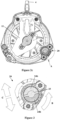
Fig. 2b is a front view of a cross-section through line F-F of the fall arrest device inFig. 2a ; -
Fig. 2c is a front view of a cross-section through line G-G of the fall arrest device inFig. 2a ; -
Fig. 3 is an expanded view of detail A of the fall arrest device inFig. 2c ; -
Fig. 4a is a rear view of a cross-section through line H-H of the fall arrest device inFig. 2a , with the pawl in an unlocked position; and -
Fig. 4b is a rear view of a cross-section through line H-H of the fall arrest device inFig. 2a , with the pawl in a locked position. - For purposes of the description hereinafter, the terms "end", "upper", "lower", "right", "left", "vertical", "horizontal", "top", "bottom", "lateral", "longitudinal" and derivatives thereof shall relate to the invention as it is oriented in the drawing Figs.. However, it is to be understood that the invention may assume various alternative variations and step sequences, except where expressly specified to the contrary. It is also to be understood that the specific devices and processes illustrated in the attached drawings, and described in the following specification, are simply exemplary embodiments or aspects of the invention. Hence, specific dimensions and other physical characteristics related to the embodiments or aspects disclosed herein are not to be considered as limiting. In a non-limiting embodiment or aspect, the present invention is directed to a
fall arrest device 10, as illustrated inFigs. 1-4b . As discussed, the fall arrest device may be in the form of a self-retracting lanyard (or lifeline) device. - In a non-limiting embodiment or aspect, the
fall arrest device 10 includes a housing, including a front cover 1 and amain housing 2. The front cover 1 is secured to the main housing by sixfasteners 3, such as bolts. In other non-limiting embodiments or aspects, more or fewer fasteners may be used, or the front cover 1 may attach by a snap-fit arrangement to themain housing 2. Achassis frame 11 is attached to, or integral with, thehousing 2, and asuspension attachment eyelet 4 is positioned at the top of themain housing 2 via thechassis frame 11 and provides an attachment means for suspension of thefall arrest device 10 from an anchor structure (not shown). - In a non-limiting embodiment or aspect, mounted inside the housing, between plates of the
chassis 11, is a rotary shaft 5 (seeFigs. 2 and4 ). Arotatable drum 6, around which a lifeline (not shown) is wound, is mounted on the rotary shaft 5, and aconnector 7 is attached to an end of the lifeline. Theconnector 7 is suitable for clipping to a safety harness (not shown). - In a non-limiting embodiment or aspect, a drum gear 9 is mounted on the rotary shaft coaxially with the
rotatable drum 6. The drum gear 9 is configured to rotate with thedrum 6 in a first direction in response to the lifeline being rewound onto thedrum 6 and in a second direction in response to the lifeline being paid out. The drum gear 9 could be integrally formed with a rim of thedrum 6 or fitted to a rim of thedrum 6. Alternatively, an annular gear rim could be positioned to the side of the drum to rotate in unison with thedrum 6. The drum gear 9 is configured to engage (and drive) acentrifugal brake arrangement 20, as will be described hereinafter. - In a non-limiting embodiment or aspect, the
centrifugal brake arrangement 20 includes abrake housing 21 configured to house certain components including abrake gear 22. Thebrake gear 22 is effectively a rotatable brake body, and the drum gear 9 is a drive element or driver portion arranged to rotatably drive the rotation of thebrake gear 22. In a non-limiting embodiment or aspect, the rotational axis of thebrake gear 22 is parallel to, but positionally spaced (or offset) from, the coaxial rotational axis of thedrum 6 and drum gear 9. - In a non-limiting embodiment or aspect, mounted on the shaft of the
brake gear 22 is aretainer 23, arotatable seat 24a, and abrake lining 25. A pair of "floating"brake shoes 24b are mounted on therotatable seat 24a. Thesebrake shoes 24b are floating in the sense that they are able to move radially with respect to the rotational axis of thebrake gear 22 dependent upon rotational speed. In a non-limiting embodiment or aspect, only one brake shoe, or more than two brake shoes, may be provided. - In a non-limiting embodiment or aspect, the
rotatable seat 24a has a square central bore arranged to receive the square 'key' end of the shaft of thebrake gear 22 so as to ensure that therotatable seat 24a rotates in unison with thebrake gear 22. Theretainer 23 retains the lining 25, and theretainer 23 andbrake lining 25 do not rotate with thebrake gear 22. Thebrake shoes 24b rotate in an annular space defined by theretainer 23, around the rotational axis of thebrake gear 22, as they are driven by lugs on theseat 24a. Thebrake shoes 24b are able to "float" radially dependent upon the rotational speed of thebrake gear 22. In a non-limiting embodiment or aspect, the brake arrangement 20 (except for housing 21) is inserted into anaperture 26 in the front cover 1 of thefall arrest device 10. -
Fig. 2a shows a side view of a non-limiting embodiment or aspect of thefall arrest device 10 with the front cover 1 secured to themain housing 2. In a non-limiting embodiment or aspect, and as best seen inFig. 2b and3 , the drum gear 9 is mounted on the rotary shaft 5 and rotates with thedrum 6. The teeth of thebrake gear 22 mesh with the teeth of the drum gear 9, such that when the drum gear 9 rotates in direction A thebrake gear 22 rotates in an opposite direction, i.e., direction B. In this embodiment, bothgears 9, 22 are rotatable in a first and second direction (i.e. clockwise and counter clockwise), such that thegears 9, 22 are bidirectional.Fig. 2c is a cross-section through thefall arrest device 10, which is nearer the front of thedevice 10 than inFig. 2b , such that achassis frame 11 and the outer components of thebrake arrangement 20 are visible. -
Fig. 3 shows an expanded view of thebrake arrangement 20 in detail A ofFig. 2c . As the rotational speed of thebrake gear 22 increases (i.e., in direction B), the centrifugal forces (or inertia) push thebrake shoes 24b radially outwards on therotatable seat 24a into thebrake lining 25, as indicated by arrows C. The friction between thebrake shoes 24b and the lining 25 slows down the rotation of thebrake gear 22, which in turn applies a braking force to slow down the rotation of the drum gear 9. As the drum gear 9 rotates with thedrum 6 onto which the lifeline is wound, this dampens the speed at which the lifeline is retracted and paid out. Thus, even if theconnector 7 is released by the user when the lifeline is significantly unwound from thedrum 6, the speed at which the lifeline retracts is controlled by the interaction between the drum gear 9 and thebrake arrangement 20. This prevents a high impact collision between theconnector 7 and thehousing 1, 2. The dimensions and configuration of the brake gear can be tailored relative to the diameter of the drum gear 9 in order to tailor the breaking effect achieved, dependent upon factors such as the retraction spring force. - As is known with respect to SRL devices, retraction of the drum is typically achieved using a retraction spring device provided in the housing of the device and acting to bias rotation of the drum in a retraction direction with significant force to retract the drum to rewind the lifeline onto the drum. In a fall arrest event the lifeline pays out from the
drum 6 at a higher speed than in normal "safe" payout situations.Figs. 4a and 4b show the speed responsive mechanism and energy absorber arrangement of a SRL fall arrest system, which is arranged to inhibit rotation of thedrum 6 above a predetermined rotational speed. This type of speed responsive mechanism and energy absorber arrangement is disclosed in detail inWO 2016/120614 . - In a non-limiting embodiment or aspect, and as shown in
Figs. 4a and 4b , a portion of the rotary shaft 5 that extends outwardly from an outer wall of thedrum 6 includes or is in the form of acollar 36 to which is mounted anenergy absorber ring 35. Apawl carrier 31 is mounted by theenergy absorber ring 35 to thecollar 36, such that, when fitted, theenergy absorber ring 35 is energized. In particular, this is effectuated by providing an interference fit, such that thecollar 36 andpawl carrier 31 effectively rotate together until an applied torque of a predetermined level is applied between thecollar 36 and thepawl carrier 31. - In a non-limiting embodiment or aspect, the
device 10 comprises astop 30 disposed below thesuspension eyelet 4, wherein thestop 30 is attached to thechassis frame 11. In this particular embodiment, thepawl carrier 31 comprises three pivotally- mountedpawls 32. Thepawls 32 are spaced apart, with eachpawl 32 being positioned at an apex of thepawl carrier 31. Eachpawl 32 is biased radially inwards towards an inactive position by arespective biasing spring 33. In other non-limiting embodiments or aspects, more, or less than threepawls 32 may be provided. - When the lifeline is retracted or paid out at a speed which is lower than a predetermined threshold, the
pawls 32 remain in the inactive position and thepawl carrier 31 simply rotates past thestop 30, as shown inFig. 4a . In response to thedrum 6 reaching the threshold rotational speed, thepawl carrier 31 and thepawls 32 are rotated against the biasing force of thesprings 33. This causes thepawls 32 to pivot radially outwards into an active position, as show inFig. 4b . In this position thepawls 32 cannot rotate past thestop 30 and so thepawl carrier 31 quickly locks in the position shown inFig. 4b , thereby preventing thedrum 6 from rotating and arresting a user's decent. Once this occurs, thepawl carrier 31 is locked against and fixed with respect to thestop 30, together with thecollar 36, the shaft 5 and thedrum 6. If the torque applied by the fall arrest event is sufficient, thedrum 6 and the shaft 5 will tend to continue rotation. - The function of the resilient
energy absorber ring 35 is to absorb energy and slow the rotation of thedrum 6 when the speed responsive engagement mechanism is activated, as inFig. 4b . In this case, theenergy absorber ring 35 will rotate with either thecollar 36 or thepawl carrier 31, and the relative rotation of the other of either thecollar 36 or thepawl carrier 31 with respect to theenergy absorber ring 35 will ensure energy is absorbed until the fall is completely arrested. - In a non-limiting embodiment or aspect, other known speed responsive mechanisms may be used, for example the ratchet and pawl speed responsive mechanism described in
WO 2008/007119 . - In a non-limiting embodiment or aspect, the energy absorber ring may also be replaced by other known energy absorber arrangements, such as a friction brake device or plastically deformable metallic strip arrangements that are plastically deformed during deployment in order to absorb energy.
- In a non-limiting embodiment or aspect, the drum gear and the brake gear can be replaced by rollers or other rotatable bodies. The rim of the drum (or a body attached to rotate with the drum) may act as a roller to drive a brake roller arrangement in place of a brake gear.
- In a non-limiting embodiment or aspect, the drum gear or roller and the brake gear or roller may be configured to rotate in only a single direction. Thus, the brake arrangement may only be operable to damp the rotation of the drum in a single direction, either during retraction of the safety line or paying out of the safety line. A one-way bearing or "sprag clutch" may be utilized to achieve this one-way effect.
- It will be appreciated that the brake arrangement does not have to be a centrifugal brake arrangement, as shown above. For example, the brake arrangement could be an eddy current brake arrangement.
Claims (15)
- A self-retracting lifeline fall arrest device (10) comprising:a rotatable drum (6) for winding a lifeline; anda brake arrangement (20) comprising a rotatable brake body (22) arranged to rotate in response to rotation of the drum (6);wherein rotation of the rotatable brake body (22) applies a braking force to the drum (6) as the lifeline is being retracted onto the drum;wherein the rotatable brake body (22) engages the rotatable drum (6), such that the rotatable drum (6) drives the rotation of the brake body (22),the self-retracting lifeline fall arrest device (10) further comprising:a speed responsive mechanism arranged to inhibit the drum rotation above a predetermined rotational speed,wherein the speed responsive engagement mechanism is provided separate from and in addition to the brake arrangement (20).
- The self-retracting lifeline device of claim 1, wherein the rotational axis of the rotatable brake body (22) is spaced from the rotational axis of the drum (6).
- The self-retracting lifeline device of any preceding claim, wherein the rotational axis of the rotatable drum (6) and the rotational axis of the rotatable brake body (22) are aligned in the same direction.
- The self-retracting lifeline device of any preceding claim, wherein the rotatable drum (6) is provided with a driver portion (9) which drives the rotation of the rotatable brake body (22), the driver portion (9) arranged to be rotated by the drum (6).
- The self-retracting lifeline device of claim 4, wherein the driver portion (9) is a drive ring which is coaxial with the drum (6), or wherein the driver portion (9) is a drive ring having a rotational axis that is coaxial with the rotational axis of the drum (6).
- The self-retracting lifeline device of claim 4, wherein the driver portion (9) is the circumferential perimeter of the drum (6).
- The self-retracting lifeline device of any of claims 4 to 6, wherein one or both of the driver portion (9) and the rotatable brake body (22) have gear or cog rings that operate to drive the rotatable brake body.
- The self-retracting lifeline device of any preceding claim, wherein the brake arrangement (20) is a centrifugal brake arrangement.
- The self-retracting lifeline device of claim 8, wherein the centrifugal brake arrangement (20) comprises at least one brake shoe (24b) slidably and/or float mounted on the rotatable brake body (22), wherein in response to rotation of the rotatable brake body (22) the at least one brake shoe (24b) is configured to slidably move outwards from an inactive position towards an active position, wherein in the active position the at least one brake shoe (24b) contacts an abutment surface (25) which slows the rotation of the rotatable brake body (22).
- The self-retracting lifeline device of claim 9, wherein the at least one brake shoe (24b) is slidably and/or float mounted on a rotatable seat (24a) driven by the rotatable brake body (22); and/or
wherein the abutment surface is a brake lining (25). - The self-retracting lifeline device of any preceding claim, further comprising a re-winding mechanism configured to rewind the lifeline onto the drum (6).
- The self-retracting lifeline device of any preceding claim, wherein the rotatable brake body (22) applies a braking force when the drum rotates in a first direction to rewind the lifeline onto the drum (6) but not when the drum (6) rotates in a second direction to payout the lifeline.
- The self-retracting lifeline device of claim 12, wherein the brake arrangement (20) comprises a one-way bearing or sprag clutch in communication with the rotatable brake body (22), such that the rotatable brake body (22) freewheels when the drum (6) rotates in the second direction.
- The self-retracting lifeline device of any preceding claim, wherein the drum (6) is mounted on a rotatable shaft (5).
- The self-retracting lifeline device of any preceding claim, further comprising an energy absorber device (35) arranged to be activated if a load above a predetermined threshold is deployed when the speed responsive mechanism (30, 31, 32) is deployed.
Applications Claiming Priority (2)
| Application Number | Priority Date | Filing Date | Title |
|---|---|---|---|
| GB1619805.3A GB2556892B (en) | 2016-11-23 | 2016-11-23 | Self-retracting lifeline fall arrest device |
| PCT/GB2017/053478 WO2018096320A1 (en) | 2016-11-23 | 2017-11-20 | Fall arrest device with controlled retraction speed |
Publications (2)
| Publication Number | Publication Date |
|---|---|
| EP3544689A1 EP3544689A1 (en) | 2019-10-02 |
| EP3544689B1 true EP3544689B1 (en) | 2024-09-18 |
Family
ID=57993824
Family Applications (1)
| Application Number | Title | Priority Date | Filing Date |
|---|---|---|---|
| EP17801767.9A Active EP3544689B1 (en) | 2016-11-23 | 2017-11-20 | Fall arrest device with controlled retraction speed |
Country Status (5)
| Country | Link |
|---|---|
| US (1) | US11938350B2 (en) |
| EP (1) | EP3544689B1 (en) |
| CN (1) | CN110022945B (en) |
| GB (1) | GB2556892B (en) |
| WO (1) | WO2018096320A1 (en) |
Cited By (1)
| Publication number | Priority date | Publication date | Assignee | Title |
|---|---|---|---|---|
| TWI910047B (en) * | 2025-05-09 | 2025-12-21 | 振鋒企業股份有限公司 | Fall arrestor |
Families Citing this family (18)
| Publication number | Priority date | Publication date | Assignee | Title |
|---|---|---|---|---|
| US11117002B2 (en) * | 2018-02-09 | 2021-09-14 | Pure Safety Group, Inc. | Brake assembly for use with retractable lifeline assembly |
| US11633634B2 (en) * | 2018-04-06 | 2023-04-25 | Msa Technology, Llc | Cut-resistant leading edge fall arrest system and method |
| EP4031254B1 (en) | 2019-09-20 | 2025-07-09 | Trublue LLC | Lock-off descent control systems and devices |
| GB2588927B (en) * | 2019-11-14 | 2024-04-17 | Latchways Plc | Settable length fall arrest device |
| CN110885008B (en) * | 2019-11-14 | 2022-06-10 | 金华捷科工具有限公司 | Buffering type speed difference falling protector |
| CN115348886B (en) * | 2020-03-18 | 2024-10-15 | 特鲁布鲁有限公司 | Line distribution device |
| CN114198438B (en) * | 2020-09-18 | 2023-08-01 | 广东电网有限责任公司 | A rotating swing arm type anti-fall self-locking safety device |
| US20220105374A1 (en) * | 2020-10-02 | 2022-04-07 | Msa Technology, Llc | Self-Retracting Device and Axle Therefor |
| US10987983B1 (en) * | 2020-10-29 | 2021-04-27 | King Abdulaziz University | Dampening safety device able to attach to a soft towline and methods for use |
| US12076594B2 (en) * | 2020-11-23 | 2024-09-03 | Yoke Industrial Corp. | Fall arrester |
| US12599791B2 (en) * | 2020-12-07 | 2026-04-14 | Werner Co. | Self-retracting lifeline housing |
| USD1024449S1 (en) * | 2020-12-07 | 2024-04-23 | Werner Co. | Self-retracting lifeline housing |
| TWI748860B (en) * | 2021-02-01 | 2021-12-01 | 貝加工業有限公司 | Temporary horizontal lifeline device |
| US20220305308A1 (en) * | 2021-03-26 | 2022-09-29 | Msa Technology, Llc | Two-Part Locking Polymer Hub for Cable Self-Retracting Device |
| CN113368420A (en) * | 2021-06-21 | 2021-09-10 | 南京林业大学 | Buffering type speed difference anti-falling device |
| US20240285986A1 (en) * | 2023-02-23 | 2024-08-29 | Msa Technology, Llc | Systems and Methods for Tracking Lifeline Payout and Retraction |
| TWI902494B (en) * | 2024-10-15 | 2025-10-21 | 振鋒企業股份有限公司 | Anti-fall device for the locking tooth of the lifting ring connection |
| TWI908600B (en) * | 2025-02-05 | 2025-12-11 | 彰茂企業股份有限公司 | Fall arrester structure |
Citations (2)
| Publication number | Priority date | Publication date | Assignee | Title |
|---|---|---|---|---|
| US4448284A (en) * | 1982-02-26 | 1984-05-15 | Renzo Ciabo | People rescue device |
| US20100308149A1 (en) * | 2009-03-10 | 2010-12-09 | Holmes Solutions Limited | Line dispensing device with eddy current breaking for use with climbing and evacuation |
Family Cites Families (43)
| Publication number | Priority date | Publication date | Assignee | Title |
|---|---|---|---|---|
| US1875335A (en) * | 1932-09-06 | Mining machine | ||
| US197899A (en) * | 1877-12-04 | Improvement in fire-escapes | ||
| US2761650A (en) * | 1953-07-06 | 1956-09-04 | Construction D App De Securite | Load-lowering machine |
| US2791397A (en) * | 1954-11-24 | 1957-05-07 | Inland Steel Co | Safety reel |
| US3052426A (en) * | 1960-07-21 | 1962-09-04 | Vickers Armstrongs Aircraft | Cable-braking apparatus |
| US3596849A (en) * | 1968-06-20 | 1971-08-03 | Vacuum Cleaner Corp Of America | Magnetic releasable locking mechanism for cord reels |
| US3985047A (en) * | 1974-11-04 | 1976-10-12 | Mercury Winch Manufacturing Ltd. | Winch drive mechanism |
| US4018423A (en) * | 1975-10-16 | 1977-04-19 | The United States Of America As Represented By The Administrator Of The National Aeronautics And Space Administration | Emergency descent device |
| US4026385A (en) * | 1976-01-19 | 1977-05-31 | Murukurthy Rao K | Ladderless safety escape device |
| JPS604013B2 (en) * | 1980-12-17 | 1985-02-01 | 株式会社高田工場 | Emergency locking seat belt retractor |
| US4446884A (en) * | 1981-06-08 | 1984-05-08 | Rader Jr Homer J | Take-up reel with controlled rewind velocity |
| US4489919A (en) * | 1983-03-21 | 1984-12-25 | Meyer Ostrobrod | Safety winch with disengageable drive |
| US4657201A (en) * | 1984-11-06 | 1987-04-14 | Thomas Munroe | Fishing reel |
| EP0247818A3 (en) * | 1986-05-28 | 1989-04-05 | Barrow Hepburn Equipment Ltd | Fall-arrest apparatus |
| US4938435A (en) * | 1988-12-30 | 1990-07-03 | Frost Engineering Development Corporation | Personnel lowering device |
| US5348117A (en) * | 1992-08-12 | 1994-09-20 | Pickering Gregory R | Rescue system |
| US5624085A (en) * | 1994-06-15 | 1997-04-29 | Kyoto Measuring Instruments Corp. | Tape measure |
| US5799342A (en) * | 1995-08-29 | 1998-09-01 | Last; Harry J. | Manual cover drive for swimming pools |
| US5984276A (en) * | 1998-09-29 | 1999-11-16 | Tri-Motion Industries, Inc. | Cable retraction speed limiter for air balancing hoist |
| DE60133201T2 (en) * | 2000-07-06 | 2009-04-30 | Mine Safety Appliances Co. | DEVICE FOR CONTROLLED HERB LEAVING |
| CN2580987Y (en) * | 2002-09-30 | 2003-10-22 | 张海军 | Differential automatic fall preventing device |
| US7281620B2 (en) * | 2003-09-05 | 2007-10-16 | D B Industries, Inc. | Self-retracting lifeline |
| GB2440134B (en) * | 2006-07-14 | 2011-04-20 | Latchways Plc | Speed responsive engagement device |
| EP2185241B1 (en) * | 2007-08-24 | 2017-05-17 | RENTON, Julian Elwyn | Height rescue apparatus |
| US7780146B2 (en) * | 2007-09-28 | 2010-08-24 | D B Industries, Inc. | Retrieval assembly |
| US8245817B2 (en) * | 2008-08-04 | 2012-08-21 | D B Industries, Inc. | Self-rescue safety device |
| GB2467953B (en) * | 2009-02-20 | 2013-07-17 | Latchways Plc | Fall arrest system safety device |
| US9764172B2 (en) * | 2009-03-09 | 2017-09-19 | D B Industries, Llc | Safety device with fall arrest and descending modes |
| US10688323B2 (en) * | 2009-03-09 | 2020-06-23 | D B Industries, Llc | Safety device with fall arrest and descending modes |
| EP2512966B1 (en) * | 2009-12-17 | 2018-02-07 | Reel-Tech Pty Ltd | Hose reel rewind speed control |
| EP2516020B1 (en) * | 2009-12-23 | 2015-05-27 | D B Industries, LLC | Fall protection safety device with a braking mechanism |
| US8998121B2 (en) * | 2010-05-04 | 2015-04-07 | Vandor Corporation | Reel stand brake system |
| US9199103B2 (en) * | 2010-05-12 | 2015-12-01 | Msa Technology, Llc | Fall protection arrangement |
| GB201019462D0 (en) * | 2010-11-18 | 2010-12-29 | Latchways Plc | Rescue descender system |
| GB201112901D0 (en) * | 2011-07-27 | 2011-09-14 | Renton Julian E | Height rescue apparatus |
| GB201118597D0 (en) * | 2011-10-27 | 2011-12-07 | Latchways Plc | Fall arrest system safety device |
| US9121462B2 (en) * | 2011-10-28 | 2015-09-01 | D B Industries, Llc | Self-retracting lifeline |
| US20140262616A1 (en) * | 2013-03-14 | 2014-09-18 | Nathaniel Ray Cullum | Ladder and Equipment Leash system and method |
| NL2011756C2 (en) * | 2013-08-05 | 2015-02-09 | Evacuator Internat Property B V | Device for evacuating individuals. |
| GB2535142B (en) | 2015-01-28 | 2020-07-29 | Latchways Plc | Energy absorber and fall arrest system safety device |
| CN105987157B (en) * | 2015-02-13 | 2019-01-08 | 梅思安(苏州)安全设备研发有限公司 | A kind of deceleration device |
| US9618891B1 (en) * | 2015-10-27 | 2017-04-11 | Lexmark International, Inc. | Bi-directional spring brake for a photoductive drum |
| US20190209877A1 (en) * | 2018-01-08 | 2019-07-11 | Pure Safety Group, Inc. | Retractable lifeline assembly |
-
2016
- 2016-11-23 GB GB1619805.3A patent/GB2556892B/en active Active
-
2017
- 2017-11-20 CN CN201780072283.2A patent/CN110022945B/en active Active
- 2017-11-20 EP EP17801767.9A patent/EP3544689B1/en active Active
- 2017-11-20 US US16/347,280 patent/US11938350B2/en active Active
- 2017-11-20 WO PCT/GB2017/053478 patent/WO2018096320A1/en not_active Ceased
Patent Citations (2)
| Publication number | Priority date | Publication date | Assignee | Title |
|---|---|---|---|---|
| US4448284A (en) * | 1982-02-26 | 1984-05-15 | Renzo Ciabo | People rescue device |
| US20100308149A1 (en) * | 2009-03-10 | 2010-12-09 | Holmes Solutions Limited | Line dispensing device with eddy current breaking for use with climbing and evacuation |
Cited By (1)
| Publication number | Priority date | Publication date | Assignee | Title |
|---|---|---|---|---|
| TWI910047B (en) * | 2025-05-09 | 2025-12-21 | 振鋒企業股份有限公司 | Fall arrestor |
Also Published As
| Publication number | Publication date |
|---|---|
| GB2556892A (en) | 2018-06-13 |
| WO2018096320A1 (en) | 2018-05-31 |
| CN110022945B (en) | 2023-05-09 |
| GB201619805D0 (en) | 2017-01-04 |
| US20190275356A1 (en) | 2019-09-12 |
| US11938350B2 (en) | 2024-03-26 |
| GB2556892B (en) | 2022-04-27 |
| CN110022945A (en) | 2019-07-16 |
| EP3544689A1 (en) | 2019-10-02 |
Similar Documents
| Publication | Publication Date | Title |
|---|---|---|
| US11938350B2 (en) | Fall arrest device with controlled retraction speed | |
| EP3423162B1 (en) | Line retraction device having a damper assembly | |
| EP2958635B1 (en) | Fall arrest device | |
| US7744063B2 (en) | Safety device | |
| CN107427705B (en) | Energy absorber arrangement and fall arrest device | |
| EP2777771B1 (en) | Fall Protection Safety Device with a Braking Mechanism | |
| EP0740570B1 (en) | Clutch mechanism for use in safety apparatus | |
| EP2726157B1 (en) | Fall arrester | |
| WO2008139127A1 (en) | Safety device | |
| KR101376047B1 (en) | Brake assembly for a self-retracting lifeline | |
| HK1005332B (en) | Clutch mechanism for use in safety apparatus | |
| EP0687482A2 (en) | A device and method for arresting a fall | |
| AU2006314264B2 (en) | Safety device | |
| JPH0631008A (en) | Fall preventive device for operation in elevated place |
Legal Events
| Date | Code | Title | Description |
|---|---|---|---|
| STAA | Information on the status of an ep patent application or granted ep patent |
Free format text: STATUS: UNKNOWN |
|
| STAA | Information on the status of an ep patent application or granted ep patent |
Free format text: STATUS: THE INTERNATIONAL PUBLICATION HAS BEEN MADE |
|
| PUAI | Public reference made under article 153(3) epc to a published international application that has entered the european phase |
Free format text: ORIGINAL CODE: 0009012 |
|
| STAA | Information on the status of an ep patent application or granted ep patent |
Free format text: STATUS: REQUEST FOR EXAMINATION WAS MADE |
|
| 17P | Request for examination filed |
Effective date: 20190408 |
|
| AK | Designated contracting states |
Kind code of ref document: A1 Designated state(s): AL AT BE BG CH CY CZ DE DK EE ES FI FR GB GR HR HU IE IS IT LI LT LU LV MC MK MT NL NO PL PT RO RS SE SI SK SM TR |
|
| AX | Request for extension of the european patent |
Extension state: BA ME |
|
| DAV | Request for validation of the european patent (deleted) | ||
| DAX | Request for extension of the european patent (deleted) | ||
| STAA | Information on the status of an ep patent application or granted ep patent |
Free format text: STATUS: EXAMINATION IS IN PROGRESS |
|
| 17Q | First examination report despatched |
Effective date: 20221012 |
|
| P01 | Opt-out of the competence of the unified patent court (upc) registered |
Effective date: 20230626 |
|
| GRAP | Despatch of communication of intention to grant a patent |
Free format text: ORIGINAL CODE: EPIDOSNIGR1 |
|
| STAA | Information on the status of an ep patent application or granted ep patent |
Free format text: STATUS: GRANT OF PATENT IS INTENDED |
|
| INTG | Intention to grant announced |
Effective date: 20240415 |
|
| GRAS | Grant fee paid |
Free format text: ORIGINAL CODE: EPIDOSNIGR3 |
|
| GRAA | (expected) grant |
Free format text: ORIGINAL CODE: 0009210 |
|
| STAA | Information on the status of an ep patent application or granted ep patent |
Free format text: STATUS: THE PATENT HAS BEEN GRANTED |
|
| AK | Designated contracting states |
Kind code of ref document: B1 Designated state(s): AL AT BE BG CH CY CZ DE DK EE ES FI FR GB GR HR HU IE IS IT LI LT LU LV MC MK MT NL NO PL PT RO RS SE SI SK SM TR |
|
| REG | Reference to a national code |
Ref country code: GB Ref legal event code: FG4D |
|
| REG | Reference to a national code |
Ref country code: CH Ref legal event code: EP |
|
| REG | Reference to a national code |
Ref country code: DE Ref legal event code: R096 Ref document number: 602017084937 Country of ref document: DE |
|
| REG | Reference to a national code |
Ref country code: IE Ref legal event code: FG4D |
|
| REG | Reference to a national code |
Ref country code: LT Ref legal event code: MG9D |
|
| PG25 | Lapsed in a contracting state [announced via postgrant information from national office to epo] |
Ref country code: NO Free format text: LAPSE BECAUSE OF FAILURE TO SUBMIT A TRANSLATION OF THE DESCRIPTION OR TO PAY THE FEE WITHIN THE PRESCRIBED TIME-LIMIT Effective date: 20241218 |
|
| PG25 | Lapsed in a contracting state [announced via postgrant information from national office to epo] |
Ref country code: GR Free format text: LAPSE BECAUSE OF FAILURE TO SUBMIT A TRANSLATION OF THE DESCRIPTION OR TO PAY THE FEE WITHIN THE PRESCRIBED TIME-LIMIT Effective date: 20241219 Ref country code: FI Free format text: LAPSE BECAUSE OF FAILURE TO SUBMIT A TRANSLATION OF THE DESCRIPTION OR TO PAY THE FEE WITHIN THE PRESCRIBED TIME-LIMIT Effective date: 20240918 |
|
| PG25 | Lapsed in a contracting state [announced via postgrant information from national office to epo] |
Ref country code: BG Free format text: LAPSE BECAUSE OF FAILURE TO SUBMIT A TRANSLATION OF THE DESCRIPTION OR TO PAY THE FEE WITHIN THE PRESCRIBED TIME-LIMIT Effective date: 20240918 |
|
| PG25 | Lapsed in a contracting state [announced via postgrant information from national office to epo] |
Ref country code: LV Free format text: LAPSE BECAUSE OF FAILURE TO SUBMIT A TRANSLATION OF THE DESCRIPTION OR TO PAY THE FEE WITHIN THE PRESCRIBED TIME-LIMIT Effective date: 20240918 |
|
| PG25 | Lapsed in a contracting state [announced via postgrant information from national office to epo] |
Ref country code: HR Free format text: LAPSE BECAUSE OF FAILURE TO SUBMIT A TRANSLATION OF THE DESCRIPTION OR TO PAY THE FEE WITHIN THE PRESCRIBED TIME-LIMIT Effective date: 20240918 |
|
| REG | Reference to a national code |
Ref country code: NL Ref legal event code: MP Effective date: 20240918 |
|
| PG25 | Lapsed in a contracting state [announced via postgrant information from national office to epo] |
Ref country code: RS Free format text: LAPSE BECAUSE OF FAILURE TO SUBMIT A TRANSLATION OF THE DESCRIPTION OR TO PAY THE FEE WITHIN THE PRESCRIBED TIME-LIMIT Effective date: 20241218 |
|
| PG25 | Lapsed in a contracting state [announced via postgrant information from national office to epo] |
Ref country code: RS Free format text: LAPSE BECAUSE OF FAILURE TO SUBMIT A TRANSLATION OF THE DESCRIPTION OR TO PAY THE FEE WITHIN THE PRESCRIBED TIME-LIMIT Effective date: 20241218 Ref country code: NO Free format text: LAPSE BECAUSE OF FAILURE TO SUBMIT A TRANSLATION OF THE DESCRIPTION OR TO PAY THE FEE WITHIN THE PRESCRIBED TIME-LIMIT Effective date: 20241218 Ref country code: LV Free format text: LAPSE BECAUSE OF FAILURE TO SUBMIT A TRANSLATION OF THE DESCRIPTION OR TO PAY THE FEE WITHIN THE PRESCRIBED TIME-LIMIT Effective date: 20240918 Ref country code: HR Free format text: LAPSE BECAUSE OF FAILURE TO SUBMIT A TRANSLATION OF THE DESCRIPTION OR TO PAY THE FEE WITHIN THE PRESCRIBED TIME-LIMIT Effective date: 20240918 Ref country code: GR Free format text: LAPSE BECAUSE OF FAILURE TO SUBMIT A TRANSLATION OF THE DESCRIPTION OR TO PAY THE FEE WITHIN THE PRESCRIBED TIME-LIMIT Effective date: 20241219 Ref country code: FI Free format text: LAPSE BECAUSE OF FAILURE TO SUBMIT A TRANSLATION OF THE DESCRIPTION OR TO PAY THE FEE WITHIN THE PRESCRIBED TIME-LIMIT Effective date: 20240918 Ref country code: BG Free format text: LAPSE BECAUSE OF FAILURE TO SUBMIT A TRANSLATION OF THE DESCRIPTION OR TO PAY THE FEE WITHIN THE PRESCRIBED TIME-LIMIT Effective date: 20240918 |
|
| REG | Reference to a national code |
Ref country code: AT Ref legal event code: MK05 Ref document number: 1724194 Country of ref document: AT Kind code of ref document: T Effective date: 20240918 |
|
| PG25 | Lapsed in a contracting state [announced via postgrant information from national office to epo] |
Ref country code: NL Free format text: LAPSE BECAUSE OF FAILURE TO SUBMIT A TRANSLATION OF THE DESCRIPTION OR TO PAY THE FEE WITHIN THE PRESCRIBED TIME-LIMIT Effective date: 20240918 |
|
| PG25 | Lapsed in a contracting state [announced via postgrant information from national office to epo] |
Ref country code: IS Free format text: LAPSE BECAUSE OF FAILURE TO SUBMIT A TRANSLATION OF THE DESCRIPTION OR TO PAY THE FEE WITHIN THE PRESCRIBED TIME-LIMIT Effective date: 20250118 Ref country code: PT Free format text: LAPSE BECAUSE OF FAILURE TO SUBMIT A TRANSLATION OF THE DESCRIPTION OR TO PAY THE FEE WITHIN THE PRESCRIBED TIME-LIMIT Effective date: 20250120 |
|
| PG25 | Lapsed in a contracting state [announced via postgrant information from national office to epo] |
Ref country code: RO Free format text: LAPSE BECAUSE OF FAILURE TO SUBMIT A TRANSLATION OF THE DESCRIPTION OR TO PAY THE FEE WITHIN THE PRESCRIBED TIME-LIMIT Effective date: 20240918 Ref country code: SM Free format text: LAPSE BECAUSE OF FAILURE TO SUBMIT A TRANSLATION OF THE DESCRIPTION OR TO PAY THE FEE WITHIN THE PRESCRIBED TIME-LIMIT Effective date: 20240918 |
|
| PG25 | Lapsed in a contracting state [announced via postgrant information from national office to epo] |
Ref country code: ES Free format text: LAPSE BECAUSE OF FAILURE TO SUBMIT A TRANSLATION OF THE DESCRIPTION OR TO PAY THE FEE WITHIN THE PRESCRIBED TIME-LIMIT Effective date: 20240918 |
|
| PG25 | Lapsed in a contracting state [announced via postgrant information from national office to epo] |
Ref country code: AT Free format text: LAPSE BECAUSE OF FAILURE TO SUBMIT A TRANSLATION OF THE DESCRIPTION OR TO PAY THE FEE WITHIN THE PRESCRIBED TIME-LIMIT Effective date: 20240918 Ref country code: EE Free format text: LAPSE BECAUSE OF FAILURE TO SUBMIT A TRANSLATION OF THE DESCRIPTION OR TO PAY THE FEE WITHIN THE PRESCRIBED TIME-LIMIT Effective date: 20240918 |
|
| PG25 | Lapsed in a contracting state [announced via postgrant information from national office to epo] |
Ref country code: CZ Free format text: LAPSE BECAUSE OF FAILURE TO SUBMIT A TRANSLATION OF THE DESCRIPTION OR TO PAY THE FEE WITHIN THE PRESCRIBED TIME-LIMIT Effective date: 20240918 Ref country code: PL Free format text: LAPSE BECAUSE OF FAILURE TO SUBMIT A TRANSLATION OF THE DESCRIPTION OR TO PAY THE FEE WITHIN THE PRESCRIBED TIME-LIMIT Effective date: 20240918 |
|
| PG25 | Lapsed in a contracting state [announced via postgrant information from national office to epo] |
Ref country code: SK Free format text: LAPSE BECAUSE OF FAILURE TO SUBMIT A TRANSLATION OF THE DESCRIPTION OR TO PAY THE FEE WITHIN THE PRESCRIBED TIME-LIMIT Effective date: 20240918 Ref country code: IT Free format text: LAPSE BECAUSE OF FAILURE TO SUBMIT A TRANSLATION OF THE DESCRIPTION OR TO PAY THE FEE WITHIN THE PRESCRIBED TIME-LIMIT Effective date: 20240918 |
|
| REG | Reference to a national code |
Ref country code: DE Ref legal event code: R097 Ref document number: 602017084937 Country of ref document: DE |
|
| REG | Reference to a national code |
Ref country code: CH Ref legal event code: PL |
|
| PG25 | Lapsed in a contracting state [announced via postgrant information from national office to epo] |
Ref country code: MC Free format text: LAPSE BECAUSE OF FAILURE TO SUBMIT A TRANSLATION OF THE DESCRIPTION OR TO PAY THE FEE WITHIN THE PRESCRIBED TIME-LIMIT Effective date: 20240918 |
|
| PG25 | Lapsed in a contracting state [announced via postgrant information from national office to epo] |
Ref country code: DK Free format text: LAPSE BECAUSE OF FAILURE TO SUBMIT A TRANSLATION OF THE DESCRIPTION OR TO PAY THE FEE WITHIN THE PRESCRIBED TIME-LIMIT Effective date: 20240918 |
|
| PG25 | Lapsed in a contracting state [announced via postgrant information from national office to epo] |
Ref country code: LU Free format text: LAPSE BECAUSE OF NON-PAYMENT OF DUE FEES Effective date: 20241120 |
|
| REG | Reference to a national code |
Ref country code: CH Ref legal event code: PL |
|
| PG25 | Lapsed in a contracting state [announced via postgrant information from national office to epo] |
Ref country code: CH Free format text: LAPSE BECAUSE OF NON-PAYMENT OF DUE FEES Effective date: 20241130 |
|
| PLBE | No opposition filed within time limit |
Free format text: ORIGINAL CODE: 0009261 |
|
| STAA | Information on the status of an ep patent application or granted ep patent |
Free format text: STATUS: NO OPPOSITION FILED WITHIN TIME LIMIT |
|
| 26N | No opposition filed |
Effective date: 20250619 |
|
| GBPC | Gb: european patent ceased through non-payment of renewal fee |
Effective date: 20241218 |
|
| REG | Reference to a national code |
Ref country code: BE Ref legal event code: MM Effective date: 20241130 |
|
| PG25 | Lapsed in a contracting state [announced via postgrant information from national office to epo] |
Ref country code: SE Free format text: LAPSE BECAUSE OF FAILURE TO SUBMIT A TRANSLATION OF THE DESCRIPTION OR TO PAY THE FEE WITHIN THE PRESCRIBED TIME-LIMIT Effective date: 20240918 |
|
| PG25 | Lapsed in a contracting state [announced via postgrant information from national office to epo] |
Ref country code: GB Free format text: LAPSE BECAUSE OF NON-PAYMENT OF DUE FEES Effective date: 20241218 Ref country code: BE Free format text: LAPSE BECAUSE OF NON-PAYMENT OF DUE FEES Effective date: 20241130 |
|
| PGFP | Annual fee paid to national office [announced via postgrant information from national office to epo] |
Ref country code: FR Payment date: 20250908 Year of fee payment: 9 |
|
| PG25 | Lapsed in a contracting state [announced via postgrant information from national office to epo] |
Ref country code: IE Free format text: LAPSE BECAUSE OF NON-PAYMENT OF DUE FEES Effective date: 20241120 |
|
| PGFP | Annual fee paid to national office [announced via postgrant information from national office to epo] |
Ref country code: DE Payment date: 20250923 Year of fee payment: 9 |
|
| PG25 | Lapsed in a contracting state [announced via postgrant information from national office to epo] |
Ref country code: HU Free format text: LAPSE BECAUSE OF FAILURE TO SUBMIT A TRANSLATION OF THE DESCRIPTION OR TO PAY THE FEE WITHIN THE PRESCRIBED TIME-LIMIT; INVALID AB INITIO Effective date: 20171120 |
|
| PG25 | Lapsed in a contracting state [announced via postgrant information from national office to epo] |
Ref country code: CY Free format text: LAPSE BECAUSE OF FAILURE TO SUBMIT A TRANSLATION OF THE DESCRIPTION OR TO PAY THE FEE WITHIN THE PRESCRIBED TIME-LIMIT; INVALID AB INITIO Effective date: 20171120 |