EP3544285A1 - Image stabilization control apparatus, image capturing apparatus, image capturing system, control method, and program - Google Patents
Image stabilization control apparatus, image capturing apparatus, image capturing system, control method, and program Download PDFInfo
- Publication number
- EP3544285A1 EP3544285A1 EP18211508.9A EP18211508A EP3544285A1 EP 3544285 A1 EP3544285 A1 EP 3544285A1 EP 18211508 A EP18211508 A EP 18211508A EP 3544285 A1 EP3544285 A1 EP 3544285A1
- Authority
- EP
- European Patent Office
- Prior art keywords
- correction
- shake
- image
- correction means
- image capturing
- Prior art date
- Legal status (The legal status is an assumption and is not a legal conclusion. Google has not performed a legal analysis and makes no representation as to the accuracy of the status listed.)
- Withdrawn
Links
- 238000000034 method Methods 0.000 title claims abstract description 47
- 230000006641 stabilisation Effects 0.000 title claims abstract description 38
- 238000011105 stabilization Methods 0.000 title claims abstract description 38
- 238000012937 correction Methods 0.000 claims abstract description 315
- 230000003287 optical effect Effects 0.000 claims description 53
- 238000001514 detection method Methods 0.000 claims description 25
- 230000008859 change Effects 0.000 claims description 19
- 230000007423 decrease Effects 0.000 claims description 2
- 238000000926 separation method Methods 0.000 description 75
- 238000012545 processing Methods 0.000 description 56
- 230000006870 function Effects 0.000 description 34
- 238000004364 calculation method Methods 0.000 description 17
- 238000006243 chemical reaction Methods 0.000 description 9
- 230000004048 modification Effects 0.000 description 9
- 238000012986 modification Methods 0.000 description 9
- 238000010586 diagram Methods 0.000 description 8
- 230000002349 favourable effect Effects 0.000 description 8
- 230000007246 mechanism Effects 0.000 description 6
- 230000004044 response Effects 0.000 description 4
- 238000006073 displacement reaction Methods 0.000 description 3
- 238000004091 panning Methods 0.000 description 3
- 230000035945 sensitivity Effects 0.000 description 3
- 230000002238 attenuated effect Effects 0.000 description 2
- 238000000605 extraction Methods 0.000 description 2
- 238000003384 imaging method Methods 0.000 description 2
- 230000010354 integration Effects 0.000 description 2
- 230000003321 amplification Effects 0.000 description 1
- 238000004458 analytical method Methods 0.000 description 1
- 238000004891 communication Methods 0.000 description 1
- 238000007796 conventional method Methods 0.000 description 1
- 238000011161 development Methods 0.000 description 1
- 238000005516 engineering process Methods 0.000 description 1
- 239000000284 extract Substances 0.000 description 1
- 238000003199 nucleic acid amplification method Methods 0.000 description 1
- 238000003825 pressing Methods 0.000 description 1
- 230000008569 process Effects 0.000 description 1
- 230000009467 reduction Effects 0.000 description 1
- 230000000087 stabilizing effect Effects 0.000 description 1
- 239000013589 supplement Substances 0.000 description 1
Images



Classifications
-
- H—ELECTRICITY
- H04—ELECTRIC COMMUNICATION TECHNIQUE
- H04N—PICTORIAL COMMUNICATION, e.g. TELEVISION
- H04N23/00—Cameras or camera modules comprising electronic image sensors; Control thereof
- H04N23/60—Control of cameras or camera modules
- H04N23/68—Control of cameras or camera modules for stable pick-up of the scene, e.g. compensating for camera body vibrations
- H04N23/689—Motion occurring during a rolling shutter mode
-
- H—ELECTRICITY
- H04—ELECTRIC COMMUNICATION TECHNIQUE
- H04N—PICTORIAL COMMUNICATION, e.g. TELEVISION
- H04N23/00—Cameras or camera modules comprising electronic image sensors; Control thereof
- H04N23/60—Control of cameras or camera modules
- H04N23/68—Control of cameras or camera modules for stable pick-up of the scene, e.g. compensating for camera body vibrations
- H04N23/681—Motion detection
- H04N23/6815—Motion detection by distinguishing pan or tilt from motion
-
- H—ELECTRICITY
- H04—ELECTRIC COMMUNICATION TECHNIQUE
- H04N—PICTORIAL COMMUNICATION, e.g. TELEVISION
- H04N23/00—Cameras or camera modules comprising electronic image sensors; Control thereof
- H04N23/60—Control of cameras or camera modules
- H04N23/68—Control of cameras or camera modules for stable pick-up of the scene, e.g. compensating for camera body vibrations
- H04N23/682—Vibration or motion blur correction
- H04N23/683—Vibration or motion blur correction performed by a processor, e.g. controlling the readout of an image memory
-
- H—ELECTRICITY
- H04—ELECTRIC COMMUNICATION TECHNIQUE
- H04N—PICTORIAL COMMUNICATION, e.g. TELEVISION
- H04N23/00—Cameras or camera modules comprising electronic image sensors; Control thereof
- H04N23/60—Control of cameras or camera modules
- H04N23/68—Control of cameras or camera modules for stable pick-up of the scene, e.g. compensating for camera body vibrations
- H04N23/681—Motion detection
-
- H—ELECTRICITY
- H04—ELECTRIC COMMUNICATION TECHNIQUE
- H04N—PICTORIAL COMMUNICATION, e.g. TELEVISION
- H04N23/00—Cameras or camera modules comprising electronic image sensors; Control thereof
- H04N23/60—Control of cameras or camera modules
- H04N23/68—Control of cameras or camera modules for stable pick-up of the scene, e.g. compensating for camera body vibrations
- H04N23/681—Motion detection
- H04N23/6812—Motion detection based on additional sensors, e.g. acceleration sensors
-
- H—ELECTRICITY
- H04—ELECTRIC COMMUNICATION TECHNIQUE
- H04N—PICTORIAL COMMUNICATION, e.g. TELEVISION
- H04N23/00—Cameras or camera modules comprising electronic image sensors; Control thereof
- H04N23/60—Control of cameras or camera modules
- H04N23/68—Control of cameras or camera modules for stable pick-up of the scene, e.g. compensating for camera body vibrations
- H04N23/682—Vibration or motion blur correction
-
- H—ELECTRICITY
- H04—ELECTRIC COMMUNICATION TECHNIQUE
- H04N—PICTORIAL COMMUNICATION, e.g. TELEVISION
- H04N23/00—Cameras or camera modules comprising electronic image sensors; Control thereof
- H04N23/60—Control of cameras or camera modules
- H04N23/68—Control of cameras or camera modules for stable pick-up of the scene, e.g. compensating for camera body vibrations
- H04N23/682—Vibration or motion blur correction
- H04N23/684—Vibration or motion blur correction performed by controlling the image sensor readout, e.g. by controlling the integration time
-
- H—ELECTRICITY
- H04—ELECTRIC COMMUNICATION TECHNIQUE
- H04N—PICTORIAL COMMUNICATION, e.g. TELEVISION
- H04N23/00—Cameras or camera modules comprising electronic image sensors; Control thereof
- H04N23/60—Control of cameras or camera modules
- H04N23/68—Control of cameras or camera modules for stable pick-up of the scene, e.g. compensating for camera body vibrations
- H04N23/682—Vibration or motion blur correction
- H04N23/684—Vibration or motion blur correction performed by controlling the image sensor readout, e.g. by controlling the integration time
- H04N23/6842—Vibration or motion blur correction performed by controlling the image sensor readout, e.g. by controlling the integration time by controlling the scanning position, e.g. windowing
-
- H—ELECTRICITY
- H04—ELECTRIC COMMUNICATION TECHNIQUE
- H04N—PICTORIAL COMMUNICATION, e.g. TELEVISION
- H04N23/00—Cameras or camera modules comprising electronic image sensors; Control thereof
- H04N23/60—Control of cameras or camera modules
- H04N23/68—Control of cameras or camera modules for stable pick-up of the scene, e.g. compensating for camera body vibrations
- H04N23/682—Vibration or motion blur correction
- H04N23/685—Vibration or motion blur correction performed by mechanical compensation
- H04N23/687—Vibration or motion blur correction performed by mechanical compensation by shifting the lens or sensor position
Definitions
- the present invention relates to an image stabilization control apparatus, an image capturing apparatus, an image capturing system, a control method, and a program, and particularly to technology for performing correction regarding an influence of shake of an image capturing apparatus, using a plurality of types of methods.
- Image capturing apparatuses in recent years such as digital cameras and video cameras, are equipped with the function of performing correction regarding an influence of shake of the apparatuses on captured images. Using this function, the apparatuses can provide captured images with fine quality.
- an optical shake correction method which is a method for reducing an image blur by driving an image stabilization lens mechanism provided in an image optical system, to correct the image blur (displacement of the position of an optical image formed on an image sensor) caused by shake.
- an electronic shake correction method which is a method for stabilizing the position of a subject image in captured images that are successively output, by defining, on some pixels of the image sensor, a region that is to be output (extracted) as a captured image, and adjusting the position of the extraction region in response to shake.
- Some image capturing apparatuses employ both the optical shake correction method and the electronic shake correction method described above to realize shake correction with consideration given to characteristics of each method (Japanese Patent No. 4518197 ).
- the image capturing apparatus disclosed in Japanese Patent No. 4518197 is configured to classify the components of detected shake into high-frequency components and low-frequency components, and use the optical shake correction method to perform correction corresponding to shake of the high-frequency components, and use the electronic shake correction method to perform correction corresponding to shake of the low-frequency components.
- the image stabilization function utilizing the electronic shake correction may not be realized in a favorable manner, depending on conditions for image capturing. More specifically, under low-light intensity conditions where the shutter speed is low, for example, so-called "accumulated shake" may occur, which is a blur occurring in a subject image due to the position at which an optical image is formed being displaced during exposure, and therefore, it may be impossible to acquire a favorable image even if a region that is to be cut out is adjusted. That is, under such conditions for image capturing where the shutter speed is low, even if a region that is to be cut out is adjusted, it may be impossible to acquire a favorable output image because the captured image signals have already been influenced by accumulated shake.
- the image capturing apparatus disclosed in Japanese Patent No. 4518197 does not take such conditions for image capturing into consideration at all.
- the present invention was made in view of such problems in the conventional technique.
- the present invention provides an image stabilization control apparatus, an image capturing apparatus, an image capturing system, a control method, and a program that realize favorable shake correction corresponding to the shutter speed.
- the present invention in its first aspect provides an image stabilization control apparatus as specified in claims 1 to 9.
- the present invention in its second aspect provides an image capturing apparatus as specified in claim 10.
- the present invention in its third aspect provides an image capturing system as specified in claim 11.
- the present invention in its fourth aspect provides a method for controlling an image stabilization control apparatus as specified in claim 12.
- the present invention is applied to a digital camera 100 that is an example of an image stabilization control apparatus capable of detecting shake that has occurred, and reducing an influence of the shake on a captured image by performing two types of correction.
- the present invention is applicable to any device that is capable of detecting shake of an image capturing apparatus, and reducing an influence of the shake on a captured image by performing a plurality of types of correction.
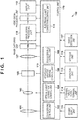
- Fig. 1 is a block diagram showing a functional configuration of a digital camera 100 according to embodiments of the present invention.
- the digital camera 100 is integrated with a lens, and is capable of performing still image shooting and moving image shooting.
- a zoom unit 101 is a lens unit that includes a zoom lens that changes the focal length from among image capturing settings, a driving mechanism for the zoom lens, a position detection sensor, and so on.
- Driving control for the zoom unit 101 is performed by a zoom driving control unit 102.
- the zoom driving control unit 102 performs driving control on the zoom lens, and is therefore configured to be able to detect the position of the zoom lens (the zoom position) on the optical axis.
- a shake correction lens unit 103 is one component of the digital camera 100 according to the present embodiment that performs correction regarding an influence of shake of the digital camera 100 (an image blur).
- the shake correction lens unit 103 includes a shake correction lens (a shift lens) for correcting displacement, caused by shake, of the position at which an optical image of the subject is formed on the image sensor, a driving mechanism for the shift lens, a position detection sensor, and so on.
- the shift lens in the shake correction lens unit 103 is moved in a direction orthogonal to the optical axis, and thus an image blur is corrected such that the position at which an optical image related to the subject is formed is maintained.
- the direction in which the shift lens is moved is not specifically limited, and need only include a directional component orthogonal to the optical axis.
- Driving control for the shake correction lens unit 103 is performed by an optical-type shake correction control unit 104. More specifically, the optical-type shake correction control unit 104 performs driving control by transmitting information (a drive signal) regarding a driving amount that has been determined in relation to correction, to the shake correction lens unit 103.
- the shake correction lens unit 103 and the optical shake correction control unit 104 serve as the first correction means according to the present invention, which realizes a correction function using an optical shake correction method for optically correcting an image blur.
- An aperture/shutter unit 105 is a unit into which an aperture and a shutter are integrated.
- An aperture adjusts the amount of incident light to the image capturing unit 109, and the shutter controls the amount of exposure by opening and closing.
- Driving control for the aperture/shutter unit 105 is performed by an aperture/shutter driving control unit 106.
- a focus unit 107 is a lens unit that includes a focus lens that performs focal point adjustment, a driving mechanism for the focus lens, a position detection sensor, and so on. As a result of the focus lens in the focus unit 107 being moved in the optical axis direction, the focal state of an optical image formed on the image sensor changes. Driving control for the focus unit 107 is performed by a focus driving control unit 108.
- the image optical system includes the zoom unit 101, the shake correction lens unit 103, the aperture/shutter unit 105, and the focus unit 107, and reflection light from the subject enters the digital camera 100 via the image optical system.
- the image capturing unit 109 includes an image sensor such as a CCD or CMOS sensor, for example, and performs photoelectric conversion on an optical image that is formed on the imaging surface of the sensor by the image optical system, and thus outputs an analogue image signal (an electrical signal) related to the captured image.
- an image sensor such as a CCD or CMOS sensor
- an analogue image signal an electrical signal related to the captured image.
- imaging sensitivity by, for example, changing sensitivity in detecting signal charge accumulated in the image sensor, or changing the amplification gain of an amplifier circuit (not shown), under the control of a control unit 119.
- An image signal processing unit 110 performs processing such as A/D conversion processing and development processing, to convert electrical signals output from the image capturing unit 109 to video signals. Also, video signals resulting from the conversion performed by the image signal processing unit 110 are processed by a video signal processing unit 111 according to the purpose.
- a display unit 112 is a display device such as an LCD, for example, and displays an image as appropriate, based on signals (output signals) output from the video signal processing unit 111. The display unit 112 performs through-the-lens display of signals that have been output as a result of image capturing, and thus functions as an electronic viewfinder.
- a power supply unit 113 supplies power required by each block of the digital camera 100 to operate.
- An external input/output terminal unit 114 receives/outputs communication signals and video signals from/to an external entity.
- a shake detection unit 117 includes an angular velocity sensor or the like. Upon the digital camera 100 shaking, the shake detection unit 117 detects and outputs the amount of shake in each of the rotational directions (the pitch direction, the yaw direction, and the roll direction).
- An electronic shake correction control unit 118 is one component of the digital camera 100 according to the present embodiment that performs correction regarding an influence of shake of the digital camera 100.
- the electronic shake correction control unit 118 realizes shake correction by controlling the video signal processing unit 111 such that the video signal processing unit 111 extracts signals in a region in which a certain subject image appears, from among image signals that have been successively captured by the image capturing unit 109, and outputs the extracted signals as output signals.
- the electronic shake correction control unit 118 performs shake correction by controlling operations of the video signal processing unit 111 such that a subject image in a specific image capturing area appears in an image related to output signals.
- the angle of view of an area corresponding to output signals is set to be smaller than the angle of view of an image capturing area that is to be subjected to photoelectric conversion performed by the image sensor, and image signals input to the video signal processing unit 111 include signals of excessive pixels that are not to be output. That is, the video signal processing unit 111 can use an area including excessive pixels to extract a region related to an output image, and can realize shake correction in the area (a movable area). Therefore, in the present embodiment, the electronic shake correction control unit 118 and the video signal processing unit 111 serve as the second correction means according to the present invention, which realizes a correction function using an electronic shake correction method for electronically correcting an image blur.
- the control unit 119 is a microcomputer, for example, and controls operations of each block of the digital camera 100. Specifically, the control unit 119 reads out operation programs for the blocks, which are stored in a storage unit 116, for example, and loads the programs to a memory (not shown) and executes the programs to control operations of the blocks.
- the storage unit 116 is a non-volatile memory, for example, and stores parameters and so on that are required for the blocks to operate, in addition to the operation programs for the blocks.
- the storage unit 116 may also be configured to store output signals (video information) and various kinds of data related to operations of the digital camera 100.
- the optical shake correction control unit 104 and the electronic shake correction control unit 118 are described as components that are separate from the control unit 119. However, these components may be realized as the control unit 119.
- An operation unit 115 is a user interface of the digital camera 100, including a shutter release button and a switch, for example. Upon detecting an operation input to the user interface, the operation unit 115 outputs a control signal corresponding to the operation, to the control unit 119.
- the operation unit 115 includes a shake correction switch that is configured to be able to turn ON and OFF a mode in which shake correction is performed (a shake correction mode).
- a shake correction mode a mode in which shake correction is performed
- the control unit 119 performs control to cause the optical shake correction control unit 104 and the electronic shake correction control unit 118 to perform operations corresponding to the mode.
- optical shake correction and electronic shake correction may be separately set to be enabled/disabled.
- the operation unit 115 includes a shooting mode selecting switch with which a still image shooting mode or a moving image shooting mode can be selected as a shooting mode that is to be executed.
- the control unit 119 Upon one of the shooting modes being selected in response to the shooting mode selecting switch being operated, the control unit 119 performs control to operate the zoom unit 101, the optical shake correction control unit 104, the aperture/shutter unit 105, and the focus unit 107 according to the selected mode.
- the operation unit 115 includes a shutter release button that is configured to sequentially turn ON a first switch (SW1) and then a second switch (SW2) according to pressed pushing depth. Upon the shutter release button being pressed by approximately halfway, the operation unit 115 outputs a SW1 signal indicating that the switch SW1 has been turned ON, and upon the shutter release button being fully pressed, the operation unit 115 outputs a SW2 signal indicating that the switch SW2 has been turned ON.
- SW1 first switch
- SW2 second switch
- the focus driving control unit 108 Upon the SW1 signal being output, the focus driving control unit 108 performs focusing by driving the focus unit 107, and the aperture/shutter driving control unit 106 sets an appropriate exposure amount by driving the aperture/shutter unit 105. Subsequently, upon the SW2 signal being output, image data that is based on an optical image that has undergone exposure performed by the image capturing unit 109 is stored in the storage unit 116.
- the operation unit 115 includes a moving image recording switch. Upon the moving image recording switch being pressed, moving image shooting is started, and upon the switch being pressed again during the recording, the recording ends. Note that the user can perform still image shooting during moving image shooting by pressing the shutter release button.
- the operation unit 115 includes a playback mode selecting switch for selecting a playback mode.
- the control unit 119 stops operations related to shake correction.
- the actuator of the shake correction lens unit 103 may be powered on, or powered off so that the shake correction lens unit 103 is fixed at a predetermined position.
- the operation unit 115 includes a magnification switch for making an instruction to change the zoom ratio.
- the zoom driving control unit 102 which has received an operational instruction via the control unit 119, drives the zoom unit 101 to move the zoom unit 101 (the zoom lens) to a specified zoom position.
- a shake correction function an image stabilization function
- the digital camera 100 the digital camera 100 according to the present embodiment with reference to the block diagram shown in Fig. 2 .
- the example in Fig. 2 shows that various blocks related to the realization of this function are realized by the optical shake correction control unit 104, the present invention is not necessarily implemented in such a way. That is, the blocks related to the realization of the function may be realized by the electronic shake correction control unit 118 or the control unit 119, or realized by some or all of the optical shake correction control unit 104, the electronic shake correction control unit 118, and the control unit 119 cooperating with each other.
- the signal is converted to digital data by an A/D conversion unit 201.
- the angular velocity sensor of the shake detection unit 117 is described as a sensor that outputs an analogue signal as an angular velocity signal.
- the sensor may be provided with an A/D conversion function.
- the angular velocity signal converted to digital data by the A/D conversion unit 201 is subjected to output adjustment performed by a gyro gain unit 202 in order to reduce fluctuation in the output values of the amount of shake, and is output to a frequency separation unit 203.
- the frequency separation unit 203 separates the input angular velocity signal into a high-frequency angular velocity signal that indicates shake corresponding to a frequency component more than the threshold value, and a low-frequency angular velocity signal that indicate shake corresponding to a frequency component less than the threshold value, and outputs them. More specifically, the frequency separation unit 203 determines a frequency that is to be used as a threshold value, based on information regarding the shutter speed related to control performed by the aperture/shutter driving control unit 106, which has been input from the control unit 119, and separates the angular velocity signal based on the threshold value.
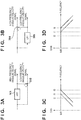
- Figs. 3A and 3B show examples of the configuration of the frequency separation unit 203.
- the frequency separation unit 203 is configured as shown in Fig. 3A , for example, the angular velocity signal that has been input (the input angular velocity signal) is input to a high-pass filter (HPF) 301, and thus high-frequency angular velocity signal indicating shake corresponding to a frequency component more than the threshold value is extracted and output.
- the high-frequency angular velocity signal is also output to a subtractor 302.
- the subtractor 302 subtracts a high-frequency angular velocity signal from the input angular velocity signal, and thus a low-frequency angular velocity signal is output.
- the frequency separation unit 203 is configured as shown in Fig.
- the input angular velocity signal is input to a low-pass filter (LPF) 303, and thus a low-frequency angular velocity signal indicating shake corresponding to a frequency component less than the threshold value is extracted and output.
- the low-frequency angular velocity signal is similarly output to a subtractor 304.
- the subtractor 304 subtracts a low-frequency angular velocity signal from the input angular velocity signal, and thus a high-frequency angular velocity signal is output.
- the frequency separation unit 203 is configured such that the threshold value (a separation frequency: a cutoff frequency) that is used to separate the input angular velocity signal into a high-frequency angular velocity signal and a low-frequency angular velocity signal can be changed according to the shutter speed, which will be described below in detail.
- the threshold value a separation frequency: a cutoff frequency
- the frequency versus gain characteristics of the HPF 301 may be those shown in Fig. 3C .
- the frequency versus gain characteristics of the LPF 303 may be those shown in Fig. 3D .
- the frequency band of the low-frequency angular velocity signal toward the low-frequency side by changing the cutoff frequency of the LPF 303 from f0 (a reference separation frequency) to f1 ( ⁇ f0).
- the high-frequency angular velocity signal is the difference between the input signal and the low-frequency angular velocity signal. Therefore, shifting the frequency band of the low-frequency angular velocity signal toward the low-frequency side is equivalent to shifting the frequency band of the high-frequency angular velocity signal toward the low-frequency side.
- shifting the cutoff frequency toward the low-frequency side it is possible to attenuate the low-frequency angular velocity signal and allocate the attenuated low-frequency angular velocity components to the high-frequency angular velocity signal.
- the frequency separation unit 203 Upon separating the input angular velocity signal, the frequency separation unit 203 outputs the separated high-frequency angular velocity signal to an integrator 204, and the separated low-frequency angular velocity signal to an integrator 206.
- the integrator 204 and a shake correction amount calculation unit 205 derive a shake correction amount related to correction operations that are to be performed by the shake correction lens unit 103, based on the high-frequency angular velocity signal output from the frequency separation unit 203.
- the integrator 204 has the function of changing characteristics in any frequency band, and integrates high-frequency angular velocity signals input from the frequency separation unit 203.
- a panning processing unit 208 performs processing to change the time constant of the integrator 204 from a reference time constant (a time constant that is initially set) according to the output from the frequency separation unit 203 or the output from the integrator.
- the panning processing unit 208 controls the time constant of the integrator 204 such that the output from the integrator 204 converges to a near-zero value as soon as possible.
- the shake correction amount calculation unit 205 derives the amount of correction that is to be performed by the shake correction lens unit 103 related to optical shake correction, based on the output signal from the integrator 204. Note that the upper limit of the amount of correction that can be performed by the shift lens on an image blur varies depending on zoom settings. Therefore, in the present embodiment, the shake correction amount calculation unit 205 specifies an area that can be corrected through optical shake correction, based on information regarding a zoom ratio output from the zoom driving control unit 102.
- the shake correction amount calculation unit 205 multiplies the input high-frequency angular velocity signal by the degree of sensitivity to set a limit on the amount of correction determined based on the high-frequency angular velocity signal, so that the shift lens is driven within the area that can be corrected, thereby deriving an ultimate correction amount.
- the optical shake correction control unit 104 performs driving control on the shake correction lens unit 103 based on the correction amount thus derived.
- the integrator 206 and a shake correction amount calculation unit 207 derive a shake correction amount related to correction operations that are to be performed by the video signal processing unit 111, based on the low-frequency angular velocity signal output from the frequency separation unit 203.
- the integrator 206 has the function of changing characteristics in any frequency band, and integrates low-frequency angular velocity signals input from the frequency separation unit 203.
- the panning processing unit 208 performs processing to control the time constant of the integrator 206.
- the shake correction amount calculation unit 207 derives the amount of correction that is to be performed by the video signal processing unit 111 related to electronic shake correction, based on the output signal from the integrator 206.
- the shake correction amount calculation unit 207 specifies an area (i.e. the movable area) that can be corrected through electronic shake correction, based on information regarding a zoom ratio output from the zoom driving control unit 102.
- the shake correction amount calculation unit 207 sets a limit on the amount of correction determined based on the input low-frequency angular velocity signal, so that a region related to the signal to be output is extracted within the movable area, thereby deriving an ultimate correction amount (the shift amount of the extraction region).
- the optical shake correction control unit 104 transmits the correction amount thus derived, to the electronic shake correction control unit 118 to cause the electronic shake correction control unit 118 to perform control on the video signal processing unit 111 based on the correction amount.
- processing in the present embodiment is realized by circuits and processors corresponding to the blocks of the digital camera 100, which are pieces of hardware.
- the present invention is not necessarily implemented in such a way, and processing performed by the blocks may be realized by a program that performs the same processing.
- the digital camera 100 uses both the optical shake correction and the electronic shake correction to correct (reduce) an image blur caused by the digital camera 100. More specifically, the digital camera 100 according to the present embodiment allocates different correction amounts (frequency bands) to the two types of correction methods respectively according to conditions regarding an image capturing environment or image capturing settings, and thus performs shake correction.
- the separation frequency of the frequency separation unit 203 is shifted to the low-frequency side compared to when the shutter speed is high or normal.
- the frequency separation unit 203 may be configured to be able to change the threshold value (the separation frequency), which is a reference for separation, according to the shutter speed (Tv).
- the separation frequency is set to be a reference separation frequency f0 (e.g.
- the digital camera 100 according to the present embodiment when the shutter speed is low, the frequency band subjected to optical shake correction is expanded toward the low-frequency side compared to when the shutter speed is high or normal, and thus accumulated shake is reduced.
- the frequency band that is to be subjected to electronic shake correction is narrowed compared to when the shutter speed is higher or normal in order to avoid excessive correction.
- the digital camera 100 according to the present embodiment can perform favorable image blur correction according to the shutter speed.
- Processing according to the flowchart is realized by the control unit 119 reading a processing program corresponding to the processing, stored in the storage unit 116, for example, loading the program to a memory (not shown), and executing the program.
- the image stabilization control processing in the following description is started when the digital camera 100, which has been set to the shake correction mode, performs through-the-lens display or moving image shooting, for example.
- step S501 the control unit 119 derives a shutter speed Tv related to image capturing.
- the shutter speed may be determined by the control unit 119 based on the result of analysis of a shooting environment and supplied to the aperture/shutter driving control unit 106, for example, or acquired from the aperture/shutter driving control unit 106.
- the shutter speed derived in this step is not limited to that determined in relation to the frame in which an image is captured, and may be derived based on the moving average related to the most recent five frames.
- step S502 the A/D conversion unit 201 and the gyro gain unit 202 acquire a digital angular velocity signal that is to be corrected in relation to the frame, based on an analogue angular velocity signal related to shake detected by the shake detection unit 117.
- the frequency separation unit 203 sets the separation frequency of the angular velocity signal based on the shutter speed derived in step S501.
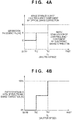
- the separation frequency may be determined by comparing the threshold value related to the shutter speed and the derived shutter speed as shown in Fig. 4A , for example. In the example shown in Fig. 4A , when the shutter speed is more than the threshold value Th1, which is a reference separation frequency, the separation frequency is set to be f0, and when the shutter speed is more than the threshold value Th2 and is not more than the threshold value Th1, the separation frequency is set to f1, and when the shutter speed is not more than the threshold value Th2, the separation frequency is set to f2.
- the present embodiment is described assuming that a threshold value is set for the shutter speed and the separation frequency is set in comparison with the threshold value.
- the present invention is not necessarily implemented in such a way. As described above, the lower the shutter speed is, the longer the exposure time is, and as a result, the influence of accumulated shake on the output signal may be prominent. Therefore, the present invention may be implemented such that the lower the shutter speed, the lower the separation frequency.
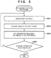
- step S504 the control unit 119 determines whether or not the shake correction mode has been cancelled. Upon determining that the shake correction mode has been cancelled, the control unit 119 ends the image stabilization control processing. Upon determining that the shake correction mode has not been cancelled, the control unit 119 returns processing to step S501, and repeats the same processing on the next frame (or the frame for which the shutter speed determination is to be performed).
- the image stabilization control apparatus it is possible to change the amount of correction allocated to electronic shake correction and optical shake correction in accordance with shutter speed, and to realize favorable image blur correction, further consideration given to conditions for image capturing.
- the correction allocation change may be determined considering not only the shutter speed but also other image capturing settings or the like. For example, the amount of correction that can be applied to optical shake correction and electronic shake correction is determined based on at least one of the focal length and the zoom ratio. Therefore, the correction allocation change may be performed with consideration given to them. More specifically, the movable area that is to be subjected to correction performed by the video signal processing unit 111 is determined at least one of the focal length and the zoom ratio, and therefore the frequency separation unit 203 may specify the frequency band that can be allocated to the electronic shake correction control unit 118, based on the movable area.
- the movable area for the video signal processing unit 111 is narrowed according to the shutter speed so as to be no greater than its maximum area determined based on at least one of the focal length and the zoom ratio.
- the movable area change may be performed by determining the proportion (the usage ratio) of excessive pixels used for electronic shake correction, to the maximum movable area, according to the shutter speed.
- the entire movable area (the maximum area) determined based on at least one of the focal length and the zoom ratio is determined to be used for electronic shake correction.
- the frequency separation unit 203 may change the separation frequency based on information regarding the limitation on the changed movable area so that the angular velocity signal in the frequency band that cannot be corrected in the area is to be corrected by the shake correction lens unit 103.
- the first embodiment and the modification above show a mode in which the present invention is applied to the digital camera 100 integrated with a lens.
- the present invention is not limited in such a way.
- the present invention is applicable to an interchangeable lens image capturing apparatus. That is, the present invention can be implemented if the components for optical shake correction and components for electronic shake correction are respectively provided in separate devices that are to be integrated into one piece when used.
- the following embodiment describes a mode in which the present invention is implemented as an image capturing system that includes a camera body and an interchangeable lens.
- the image capturing system according to the present embodiment further includes the function of performing shake correction by controlling the position and the rotation of the image sensor, in addition to optical shake correction by driving the shift lens and electronic shake correction performed by controlling a region that is to be extracted from a captured image, which are described above.
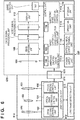
- the following describes a functional configuration of an image capturing system 600 according to the present embodiment with reference to a block diagram shown in Fig. 6 .
- the following describes characteristic components of the image capturing system 600 according to the present embodiment.
- the image capturing system 600 includes an interchangeable lens 610 and a camera body 620 that are connected to each other.
- the interchangeable lens 610 and the camera body 620 are configured to be able to communicate with each other when their respective mount contact portions 611 and 621 are in contact with each other.
- the interchangeable lens 610 includes a lens control unit 612 that is independent of the camera body 620, to control each block of the interchangeable lens 610.
- the lens control unit 612 may control operations of the blocks by loading operation programs for the blocks, stored in a storage unit (not shown), to a memory, and executing the programs.
- the interchangeable lens 610 includes a lens shake detection unit 613 that is separate from the camera body 620 and is configured to be able to detect the occurrence of shake by itself.
- the lens shake detection unit 613 may have the same configuration as the shake detection unit 117.
- the lens shake detection unit 613 includes an angular velocity sensor and so on, detect shake of the interchangeable lens 610 or the camera body 620, and outputs the amount of shake.
- the interchangeable lens 610 is configured to be able to realize a shake correction function by itself, and is also able to transmit various control amounts and so on related to shake correction to the control unit 119 via the mount contact portions 611 and 621.
- power related to the driving of the interchangeable lens 610 may be supplied from the power supply unit 113 of the camera body 620 via the mount contact portions 611 and 621.
- the image capturing unit 109 includes an image sensor configured to be rotatable about the optical axis and movable in a direction that is orthogonal to the optical axis, a driving mechanism for driving the image sensor, a state detection sensor, and so on.
- the driving of the image sensor is controlled by an image capturing shake correction control unit 622. That is, in the image capturing system 600 according to the present embodiment, the image sensor and the image capturing shake correction control unit 622 are components for correcting an image blur caused by shake of the image capturing system 600.
- the image capturing shake correction control unit 622 corrects an image blur by driving the image sensor so as to correct displacement and rotation of an optical image of the subject formed on the image sensor, caused by shake.
- the image sensor and the image capturing shake correction control unit 622 serve as a third correction means according to the present invention, which realizes a mechanical shake correction type correction function, by which an image blur is mechanically corrected.
- the camera body 620 and the interchangeable lens 610 respectively include the shake detection unit 117 and the lens shake detection unit 613. Therefore, driving control related to shake correction may be performed using the respective outputs from the camera body 620 and the interchangeable lens 610. Alternatively, driving control related to shake correction may be performed by the devices sharing an output from the shake detection unit of one of them.
- the optical shake correction control unit 104 mainly performs image stabilization control processing including correction allocation change. Therefore, information regarding the amount of shake, output by the lens control unit 612 of the interchangeable lens 610, is used to control both of the devices.
- the aperture/shutter unit 105 and the aperture/shutter driving control unit 106 are included in the camera body 620, and therefore information regarding the shutter speed is supplied to the optical shake correction control unit 104 by the control unit 119 via the mount contact portions 611 and 621.
- Fig. 7 shows that, as in the first embodiment, various blocks related to the realization of this function are realized by the optical shake correction control unit 104, the present invention is not necessarily implemented in such a way. Note that, in descriptions of components related to the shake correction function according to the present embodiment, components that are the same as those in the first embodiment related to the same function are assigned the same reference numerals and descriptions thereof are omitted.
- the integrator 206 and the shake correction amount calculation unit 207 derive a shake correction amount related to correction operations that are to be performed in the camera body 620, based on a low-frequency angular velocity signal output from the frequency separation unit 203.
- the camera body 620 has a mechanical shake correction function in addition to electronic shake correction function, and therefore the shake correction amount calculation unit 207 drives correction amounts related to both types of shake correction.
- the movable area that is to be subjected to electronic shake correction performed by the video signal processing unit 111 which is determined based on at least one of the focal length and the zoom ratio, is limited according to the shutter speed, and the shake correction amount calculation unit 207 derives the amount of shift with consideration given to the limitation.
- the amount of correction that is to be performed using the electronic shake correction method is derived such that correction is performed within the limited movable area.
- the low-frequency angular velocity signal includes frequency components that are not corrected using electronic shake correction due to the limitation. Therefore, the image capturing system 600 according to the present embodiment corrects such components using mechanical shake correction.
- the shake correction amount calculation unit 207 when the shake correction amount calculation unit 207 performs control to reduce the amount of correction that is to be performed through electronic shake correction, the amount of correction that is to be performed through mechanical shake correction related to the low-frequency angular velocity signal is derived so as to supplement the reduction.
- the mechanical and electronic shake correction amounts derived by the shake correction amount calculation unit 207 are transmitted to the electronic shake correction control unit 118 and the image capturing shake correction control unit 622 via the mount contact portions 611 and 621.
- the shake correction amount calculation unit 207 determines the amounts of correction that are to be allocated to electronic shake correction and mechanical shake correction, respectively, according to the movable area limited by the video signal processing unit 111 based on at least one of the focal length and the zoom ratio.
- the present invention is not necessarily implemented in such a way.
- a separation frequency for separating a low-frequency angular velocity signal into even smaller frequency components may be provided and allocation may be performed by changing the separation frequency according to the shutter speed.
- a low-frequency angular velocity signal may be separated with reference to a frequency that is the second threshold value according to the present invention, into an angular velocity signal with a frequency component more than the threshold value and an angular velocity signal with a frequency component less than the threshold value, and input to the integrator 206.
- such separation is performed by the frequency separation unit 203.
- the separation may be performed by another element that is configured to be able to acquire information regarding the shutter speed, the focal length, and the zoom ratio.
- the integrator 206 and the shake correction amount calculation unit 207 may process the separated angular velocity signals and derive correction amounts that are to be allocated to electronic shake correction and mechanical shake correction.
- the image capturing system 600 performs correction by three types of correction to suppress accumulated shake, and reduce the influence of shake of the image capturing system 600 on the output signal.
- Processing according to the flowchart is realized by the control unit 119 reading a processing program corresponding to the processing, stored in the storage unit 116, for example, loading the program to a memory (not shown), and executing the program.
- the image stabilization control processing in the following description is started when the camera body 620, which has been set to the shake correction mode, performs through-the-lens display or moving image shooting, for example. Note that in the image stabilization control processing according to the present embodiment, steps in which the same processing as in the image stabilization control processing according to the first embodiment are assigned the same reference numerals and descriptions thereof are omitted.
- step S501 upon receiving a shutter speed that has been derived, the optical shake correction control unit 104 acquires information regarding the zoom ratio and the focal length related to image capturing in step S801 from the zoom driving control unit 102 and the focus driving control unit 108.
- step S802 the A/D conversion unit 201 and the gyro gain unit 202 acquire a digital angular velocity signal that is to be corrected in relation to the frame, based on an analogue angular velocity signal related to shake detected by the lens shake detection unit 613.
- the frequency separation unit 203 first sets the separation frequency (the first separation frequency) for separating the high-frequency angular velocity signal that is to be corrected by the shake correction lens unit 103, based on the shutter speed.
- the first separation frequency may be set by comparing a predetermined threshold value and the shutter speed as shown in Fig. 4A .
- the frequency separation unit 203 specifies the movable area that is to be subjected to electrical shake correction performed by the video signal processing unit 111, based on information regarding the shutter speed, the zoom ratio, and the focal length. Specifically, the frequency separation unit 203 first specifies the movable area (the maximum movable area) that is to be subjected to electronic shake correction, which is independent of the shutter speed, based on information regarding the zoom ratio and the focal length. Thereafter, the frequency separation unit 203 determines whether or not to limit the movable area that is to be subjected to the correction, according to the shutter speed. The determination may be performed by comparing the predetermined threshold for the shutter speed with the shutter speed to specify the usage ratio as shown in Fig. 4B .
- the frequency separation unit 203 after performing the determination, specifies the movable area (corresponding to "the number of excessive pixels in the maximum movable area” ⁇ “the usage ratio” + “the number of pixels in the output signal") that is to be subjected to ultimate electronic shake correction.
- step S805 the frequency separation unit 203 sets the separation frequency (the second separation frequency) for separating the angular velocity signal into frequency components that are to be allocated to electronic shake correction and mechanical shake correction, respectively, based on information regarding the movable area that is to be subjected to electronic shake correction, and returns processing to step S504.
- the second separation frequency set in this step is different from the first separation frequency set in step S803 in that the second separation frequency is less than the first separation frequency and can be used to further separate the low-frequency angular velocity signal into two frequency components. The lower the shutter speed is, the smaller the movable area that is to be subjected to electronic shake correction is, compared to the maximum area.
- the frequency band (a frequency range that is less than the first separation frequency and more than the second separation frequency) that is to be allocated to mechanical shake correction is expanded according to the shutter speed.
- the second separation frequency that is used for allocation to electronic shake correction and mechanical shake correction is set in this step, and therefore the frequency separation unit 203 can separate the input angular velocity signal into signals with which the shake correction lens unit 103, the video signal processing unit 111, and the image sensor perform correction.
- the image capturing system According to the image capturing system according to the present embodiment, it is possible to suppress accumulated shake and realize favorable shake correction corresponding to the shutter speed in a system that has an optical shake correction function, an electronic shake correction function, and a mechanical shake correction function.
- the angular velocity signal is separated into components that are to be allocated to the respective shake correction methods, using the (first and second) separation frequencies, regardless of the direction in which shake correction is performed.
- the (first and second) separation frequencies may vary depending on the direction in which shake correction is performed. It is unnecessary to correct shake in all of the rotational directions using all of the shake correction methods employed in an image capturing system (a camera integrated with a lens, or a camera body and an interchangeable lens).
- the optical shake correction method and the electronic shake correction method may be used to perform shake correction in a pitch direction and a yaw direction, and shake correction in a roll direction may be performed using two methods, namely the electronic shake correction method and the mechanical shake correction method. If this is the case, angular velocity signals related to the pitch direction and the yaw direction separated using the first and second separation frequencies according to the second embodiment may be allocated to the respective correction methods. At this time, it is preferable that a frequency that is used to separate the angular velocity signal related to the roll direction so as to be allocated to the electronic shake correction method and the mechanical shake correction method may also be changed according to the shutter speed.
- Embodiment(s) of the present invention can also be realized by a computer of a system or apparatus that reads out and executes computer executable instructions (e.g., one or more programs) recorded on a storage medium (which may also be referred to more fully as a 'non-transitory computer-readable storage medium') to perform the functions of one or more of the above-described embodiment(s) and/or that includes one or more circuits (e.g., application specific integrated circuit (ASIC)) for performing the functions of one or more of the above-described embodiment(s), and by a method performed by the computer of the system or apparatus by, for example, reading out and executing the computer executable instructions from the storage medium to perform the functions of one or more of the above-described embodiment(s) and/or controlling the one or more circuits to perform the functions of one or more of the above-described embodiment(s).
- computer executable instructions e.g., one or more programs
- a storage medium which may also be referred to more fully as
- the computer may comprise one or more processors (e.g., central processing unit (CPU), micro processing unit (MPU)) and may include a network of separate computers or separate processors to read out and execute the computer executable instructions.
- the computer executable instructions may be provided to the computer, for example, from a network or the storage medium.
- the storage medium may include, for example, one or more of a hard disk, a random-access memory (RAM), a read only memory (ROM), a storage of distributed computing systems, an optical disk (such as a compact disc (CD), digital versatile disc (DVD), or Blu-ray Disc (BD)TM), a flash memory device, a memory card, and the like.
- An image stabilization control apparatus acquires information regarding a shutter speed related to image capturing that is to be performed by the image capturing apparatus, and controls to cause first correction means and second correction means that respectively employ different correction methods, to correct shake of the image capturing apparatus.
- the image stabilization control apparatus changes the allocation of correction of the shake to the first correction means and the second correction means based on information regarding the shutter speed.
Landscapes
- Engineering & Computer Science (AREA)
- Multimedia (AREA)
- Signal Processing (AREA)
- Studio Devices (AREA)
- Adjustment Of Camera Lenses (AREA)
Abstract
Description
- The present invention relates to an image stabilization control apparatus, an image capturing apparatus, an image capturing system, a control method, and a program, and particularly to technology for performing correction regarding an influence of shake of an image capturing apparatus, using a plurality of types of methods.
- Image capturing apparatuses in recent years, such as digital cameras and video cameras, are equipped with the function of performing correction regarding an influence of shake of the apparatuses on captured images. Using this function, the apparatuses can provide captured images with fine quality.
- There are various methods for detecting shake of an image capturing apparatus and performing correction regarding an influence of the shake, and such methods are each realized using a different mechanism or a different piece of software. For example, there is an optical shake correction method, which is a method for reducing an image blur by driving an image stabilization lens mechanism provided in an image optical system, to correct the image blur (displacement of the position of an optical image formed on an image sensor) caused by shake. There is also an electronic shake correction method, which is a method for stabilizing the position of a subject image in captured images that are successively output, by defining, on some pixels of the image sensor, a region that is to be output (extracted) as a captured image, and adjusting the position of the extraction region in response to shake.
- Some image capturing apparatuses employ both the optical shake correction method and the electronic shake correction method described above to realize shake correction with consideration given to characteristics of each method (Japanese Patent No.
4518197 - The image capturing apparatus disclosed in Japanese Patent No.
4518197 - However, the image stabilization function utilizing the electronic shake correction, in particular, may not be realized in a favorable manner, depending on conditions for image capturing. More specifically, under low-light intensity conditions where the shutter speed is low, for example, so-called "accumulated shake" may occur, which is a blur occurring in a subject image due to the position at which an optical image is formed being displaced during exposure, and therefore, it may be impossible to acquire a favorable image even if a region that is to be cut out is adjusted. That is, under such conditions for image capturing where the shutter speed is low, even if a region that is to be cut out is adjusted, it may be impossible to acquire a favorable output image because the captured image signals have already been influenced by accumulated shake. The image capturing apparatus disclosed in Japanese Patent No.
4518197 - The present invention was made in view of such problems in the conventional technique. The present invention provides an image stabilization control apparatus, an image capturing apparatus, an image capturing system, a control method, and a program that realize favorable shake correction corresponding to the shutter speed.
- The present invention in its first aspect provides an image stabilization control apparatus as specified in claims 1 to 9.
- The present invention in its second aspect provides an image capturing apparatus as specified in claim 10.
- The present invention in its third aspect provides an image capturing system as specified in claim 11.
- The present invention in its fourth aspect provides a method for controlling an image stabilization control apparatus as specified in claim 12.
- Further features of the present invention will become apparent from the following description of exemplary embodiments (with reference to the attached drawings).
-
-
Fig. 1 is a block diagram showing a functional configuration of adigital camera 100 according to a first embodiment and a modification of the present invention. -
Fig. 2 is a block diagram showing a configuration of a shake correction function according to the first embodiment and the modification of the present invention. -
Figs. 3A, 3B, 3C, and 3D illustrate separation of an angular velocity signal according to embodiments and the modification of the present invention. -
Figs. 4A and 4B illustrate a separation frequency that is set by afrequency separation unit 203, according to the first embodiment and the modification of the present invention. -
Fig. 5 is a flowchart illustrating image stabilization control processing that is executed by thedigital camera 100 according to the first embodiment of the present invention. -
Fig. 6 is a block diagram showing a functional configuration of an image capturingsystem 600 according to a second embodiment of the present invention. -
Fig. 7 is a block diagram showing a configuration of a shake correction function according to the second embodiment of the present invention. -
Fig. 8 is a flowchart illustrating image stabilization control processing that is executed by the image capturingsystem 600 according to the second embodiment of the present invention. - The following describes illustrative embodiments of the present invention in detail with reference to the drawings. Note that the embodiment described below is an example in which the present invention is applied to a
digital camera 100 that is an example of an image stabilization control apparatus capable of detecting shake that has occurred, and reducing an influence of the shake on a captured image by performing two types of correction. However, the present invention is applicable to any device that is capable of detecting shake of an image capturing apparatus, and reducing an influence of the shake on a captured image by performing a plurality of types of correction. -
Fig. 1 is a block diagram showing a functional configuration of adigital camera 100 according to embodiments of the present invention. In the present embodiment, thedigital camera 100 is integrated with a lens, and is capable of performing still image shooting and moving image shooting. - A
zoom unit 101 is a lens unit that includes a zoom lens that changes the focal length from among image capturing settings, a driving mechanism for the zoom lens, a position detection sensor, and so on. As a result of the zoom lens in thezoom unit 101 being moved in the optical axis direction, the focal length changes, and thus an optical image formed on the image sensor of theimage capturing unit 109 described below changes. Driving control for thezoom unit 101 is performed by a zoomdriving control unit 102. The zoomdriving control unit 102 performs driving control on the zoom lens, and is therefore configured to be able to detect the position of the zoom lens (the zoom position) on the optical axis. - A shake
correction lens unit 103 is one component of thedigital camera 100 according to the present embodiment that performs correction regarding an influence of shake of the digital camera 100 (an image blur). The shakecorrection lens unit 103 includes a shake correction lens (a shift lens) for correcting displacement, caused by shake, of the position at which an optical image of the subject is formed on the image sensor, a driving mechanism for the shift lens, a position detection sensor, and so on. The shift lens in the shakecorrection lens unit 103 is moved in a direction orthogonal to the optical axis, and thus an image blur is corrected such that the position at which an optical image related to the subject is formed is maintained. The direction in which the shift lens is moved is not specifically limited, and need only include a directional component orthogonal to the optical axis. Driving control for the shakecorrection lens unit 103 is performed by an optical-type shakecorrection control unit 104. More specifically, the optical-type shakecorrection control unit 104 performs driving control by transmitting information (a drive signal) regarding a driving amount that has been determined in relation to correction, to the shakecorrection lens unit 103. In the present embodiment, the shakecorrection lens unit 103 and the optical shakecorrection control unit 104 serve as the first correction means according to the present invention, which realizes a correction function using an optical shake correction method for optically correcting an image blur. - An aperture/
shutter unit 105 is a unit into which an aperture and a shutter are integrated. An aperture adjusts the amount of incident light to theimage capturing unit 109, and the shutter controls the amount of exposure by opening and closing. Driving control for the aperture/shutter unit 105 is performed by an aperture/shutterdriving control unit 106. - A
focus unit 107 is a lens unit that includes a focus lens that performs focal point adjustment, a driving mechanism for the focus lens, a position detection sensor, and so on. As a result of the focus lens in thefocus unit 107 being moved in the optical axis direction, the focal state of an optical image formed on the image sensor changes. Driving control for thefocus unit 107 is performed by a focusdriving control unit 108. - Note that the image optical system includes the
zoom unit 101, the shakecorrection lens unit 103, the aperture/shutter unit 105, and thefocus unit 107, and reflection light from the subject enters thedigital camera 100 via the image optical system. - The
image capturing unit 109 includes an image sensor such as a CCD or CMOS sensor, for example, and performs photoelectric conversion on an optical image that is formed on the imaging surface of the sensor by the image optical system, and thus outputs an analogue image signal (an electrical signal) related to the captured image. Note that it is possible to change imaging sensitivity by, for example, changing sensitivity in detecting signal charge accumulated in the image sensor, or changing the amplification gain of an amplifier circuit (not shown), under the control of acontrol unit 119. - An image
signal processing unit 110 performs processing such as A/D conversion processing and development processing, to convert electrical signals output from theimage capturing unit 109 to video signals. Also, video signals resulting from the conversion performed by the imagesignal processing unit 110 are processed by a videosignal processing unit 111 according to the purpose. Adisplay unit 112 is a display device such as an LCD, for example, and displays an image as appropriate, based on signals (output signals) output from the videosignal processing unit 111. Thedisplay unit 112 performs through-the-lens display of signals that have been output as a result of image capturing, and thus functions as an electronic viewfinder. - A
power supply unit 113 supplies power required by each block of thedigital camera 100 to operate. An external input/output terminal unit 114 receives/outputs communication signals and video signals from/to an external entity. Ashake detection unit 117 includes an angular velocity sensor or the like. Upon thedigital camera 100 shaking, theshake detection unit 117 detects and outputs the amount of shake in each of the rotational directions (the pitch direction, the yaw direction, and the roll direction). - An electronic shake
correction control unit 118 is one component of thedigital camera 100 according to the present embodiment that performs correction regarding an influence of shake of thedigital camera 100. The electronic shakecorrection control unit 118 realizes shake correction by controlling the videosignal processing unit 111 such that the videosignal processing unit 111 extracts signals in a region in which a certain subject image appears, from among image signals that have been successively captured by theimage capturing unit 109, and outputs the extracted signals as output signals. In other words, the electronic shakecorrection control unit 118 performs shake correction by controlling operations of the videosignal processing unit 111 such that a subject image in a specific image capturing area appears in an image related to output signals. Therefore, in a mode in which correction is performed, for example, the angle of view of an area corresponding to output signals is set to be smaller than the angle of view of an image capturing area that is to be subjected to photoelectric conversion performed by the image sensor, and image signals input to the videosignal processing unit 111 include signals of excessive pixels that are not to be output. That is, the videosignal processing unit 111 can use an area including excessive pixels to extract a region related to an output image, and can realize shake correction in the area (a movable area). Therefore, in the present embodiment, the electronic shakecorrection control unit 118 and the videosignal processing unit 111 serve as the second correction means according to the present invention, which realizes a correction function using an electronic shake correction method for electronically correcting an image blur. - The
control unit 119 is a microcomputer, for example, and controls operations of each block of thedigital camera 100. Specifically, thecontrol unit 119 reads out operation programs for the blocks, which are stored in astorage unit 116, for example, and loads the programs to a memory (not shown) and executes the programs to control operations of the blocks. Here, thestorage unit 116 is a non-volatile memory, for example, and stores parameters and so on that are required for the blocks to operate, in addition to the operation programs for the blocks. Thestorage unit 116 may also be configured to store output signals (video information) and various kinds of data related to operations of thedigital camera 100. In the present embodiment, the optical shakecorrection control unit 104 and the electronic shakecorrection control unit 118 are described as components that are separate from thecontrol unit 119. However, these components may be realized as thecontrol unit 119. - An
operation unit 115 is a user interface of thedigital camera 100, including a shutter release button and a switch, for example. Upon detecting an operation input to the user interface, theoperation unit 115 outputs a control signal corresponding to the operation, to thecontrol unit 119. - For example, the
operation unit 115 includes a shake correction switch that is configured to be able to turn ON and OFF a mode in which shake correction is performed (a shake correction mode). In a state where the shake correction switch has been operated and a shake correction mode is to be executed, thecontrol unit 119 performs control to cause the optical shakecorrection control unit 104 and the electronic shakecorrection control unit 118 to perform operations corresponding to the mode. In this control, optical shake correction and electronic shake correction may be separately set to be enabled/disabled. - Also, for example, the
operation unit 115 includes a shooting mode selecting switch with which a still image shooting mode or a moving image shooting mode can be selected as a shooting mode that is to be executed. Upon one of the shooting modes being selected in response to the shooting mode selecting switch being operated, thecontrol unit 119 performs control to operate thezoom unit 101, the optical shakecorrection control unit 104, the aperture/shutter unit 105, and thefocus unit 107 according to the selected mode. - Also, for example, the
operation unit 115 includes a shutter release button that is configured to sequentially turn ON a first switch (SW1) and then a second switch (SW2) according to pressed pushing depth. Upon the shutter release button being pressed by approximately halfway, theoperation unit 115 outputs a SW1 signal indicating that the switch SW1 has been turned ON, and upon the shutter release button being fully pressed, theoperation unit 115 outputs a SW2 signal indicating that the switch SW2 has been turned ON. - Upon the SW1 signal being output, the focus driving
control unit 108 performs focusing by driving thefocus unit 107, and the aperture/shutter drivingcontrol unit 106 sets an appropriate exposure amount by driving the aperture/shutter unit 105. Subsequently, upon the SW2 signal being output, image data that is based on an optical image that has undergone exposure performed by theimage capturing unit 109 is stored in thestorage unit 116. - Also, for example, the
operation unit 115 includes a moving image recording switch. Upon the moving image recording switch being pressed, moving image shooting is started, and upon the switch being pressed again during the recording, the recording ends. Note that the user can perform still image shooting during moving image shooting by pressing the shutter release button. - Also, for example, the
operation unit 115 includes a playback mode selecting switch for selecting a playback mode. Upon the playback mode being selected in response to the playback mode selecting switch being operated, thecontrol unit 119 stops operations related to shake correction. At this time, the actuator of the shakecorrection lens unit 103 may be powered on, or powered off so that the shakecorrection lens unit 103 is fixed at a predetermined position. - Also, for example, the
operation unit 115 includes a magnification switch for making an instruction to change the zoom ratio. Upon an instruction to change the zoom ratio being made in response to the magnification switch being operated, the zoom drivingcontrol unit 102, which has received an operational instruction via thecontrol unit 119, drives thezoom unit 101 to move the zoom unit 101 (the zoom lens) to a specified zoom position. - Next, the following describes a configuration related to a shake correction function (an image stabilization function) realized by the
digital camera 100 according to the present embodiment with reference to the block diagram shown inFig. 2 . Although the example inFig. 2 shows that various blocks related to the realization of this function are realized by the optical shakecorrection control unit 104, the present invention is not necessarily implemented in such a way. That is, the blocks related to the realization of the function may be realized by the electronic shakecorrection control unit 118 or thecontrol unit 119, or realized by some or all of the optical shakecorrection control unit 104, the electronic shakecorrection control unit 118, and thecontrol unit 119 cooperating with each other. - Upon an angular velocity signal related to shake of the
digital camera 100 being output by theshake detection unit 117, the signal is converted to digital data by an A/D conversion unit 201. In the present embodiment, the angular velocity sensor of theshake detection unit 117 is described as a sensor that outputs an analogue signal as an angular velocity signal. However, the sensor may be provided with an A/D conversion function. The angular velocity signal converted to digital data by the A/D conversion unit 201 is subjected to output adjustment performed by agyro gain unit 202 in order to reduce fluctuation in the output values of the amount of shake, and is output to afrequency separation unit 203. - With reference to a frequency that is the first threshold value according to the present invention, the
frequency separation unit 203 separates the input angular velocity signal into a high-frequency angular velocity signal that indicates shake corresponding to a frequency component more than the threshold value, and a low-frequency angular velocity signal that indicate shake corresponding to a frequency component less than the threshold value, and outputs them. More specifically, thefrequency separation unit 203 determines a frequency that is to be used as a threshold value, based on information regarding the shutter speed related to control performed by the aperture/shutter drivingcontrol unit 106, which has been input from thecontrol unit 119, and separates the angular velocity signal based on the threshold value. - Here,
Figs. 3A and 3B show examples of the configuration of thefrequency separation unit 203. If thefrequency separation unit 203 is configured as shown inFig. 3A , for example, the angular velocity signal that has been input (the input angular velocity signal) is input to a high-pass filter (HPF) 301, and thus high-frequency angular velocity signal indicating shake corresponding to a frequency component more than the threshold value is extracted and output. The high-frequency angular velocity signal is also output to asubtractor 302. Thesubtractor 302 subtracts a high-frequency angular velocity signal from the input angular velocity signal, and thus a low-frequency angular velocity signal is output. If thefrequency separation unit 203 is configured as shown inFig. 3B , for example, the input angular velocity signal is input to a low-pass filter (LPF) 303, and thus a low-frequency angular velocity signal indicating shake corresponding to a frequency component less than the threshold value is extracted and output. The low-frequency angular velocity signal is similarly output to asubtractor 304. Thesubtractor 304 subtracts a low-frequency angular velocity signal from the input angular velocity signal, and thus a high-frequency angular velocity signal is output. - The
frequency separation unit 203 according to the present embodiment is configured such that the threshold value (a separation frequency: a cutoff frequency) that is used to separate the input angular velocity signal into a high-frequency angular velocity signal and a low-frequency angular velocity signal can be changed according to the shutter speed, which will be described below in detail. For example, if thefrequency separation unit 203 is configured as shown inFig. 3A , the frequency versus gain characteristics of theHPF 301 may be those shown inFig. 3C . As shown in the figure, it is possible to shift the frequency band of the high-frequency angular velocity signal toward the low-frequency side by changing the cutoff frequency of theHPF 301 from f0 (a reference separation frequency) to f1 (<f0). Also, for example, if thefrequency separation unit 203 is configured as shown inFig. 3B , the frequency versus gain characteristics of theLPF 303 may be those shown inFig. 3D . As shown in the figure, it is possible to shift the frequency band of the low-frequency angular velocity signal toward the low-frequency side by changing the cutoff frequency of theLPF 303 from f0 (a reference separation frequency) to f1 (<f0). The high-frequency angular velocity signal is the difference between the input signal and the low-frequency angular velocity signal. Therefore, shifting the frequency band of the low-frequency angular velocity signal toward the low-frequency side is equivalent to shifting the frequency band of the high-frequency angular velocity signal toward the low-frequency side. By shifting the cutoff frequency toward the low-frequency side, it is possible to attenuate the low-frequency angular velocity signal and allocate the attenuated low-frequency angular velocity components to the high-frequency angular velocity signal. - Upon separating the input angular velocity signal, the
frequency separation unit 203 outputs the separated high-frequency angular velocity signal to anintegrator 204, and the separated low-frequency angular velocity signal to anintegrator 206. - The
integrator 204 and a shake correctionamount calculation unit 205 derive a shake correction amount related to correction operations that are to be performed by the shakecorrection lens unit 103, based on the high-frequency angular velocity signal output from thefrequency separation unit 203. Theintegrator 204 has the function of changing characteristics in any frequency band, and integrates high-frequency angular velocity signals input from thefrequency separation unit 203. When theintegrator 204 performs integration processing, a panningprocessing unit 208 performs processing to change the time constant of theintegrator 204 from a reference time constant (a time constant that is initially set) according to the output from thefrequency separation unit 203 or the output from the integrator. This is because if the time constant of theintegrator 204 is large, it takes a long time for the increased output to converge to a near-zero value, and the limit of shake correction may be reached before the convergence. That is, the panningprocessing unit 208 controls the time constant of theintegrator 204 such that the output from theintegrator 204 converges to a near-zero value as soon as possible. - The shake correction
amount calculation unit 205 derives the amount of correction that is to be performed by the shakecorrection lens unit 103 related to optical shake correction, based on the output signal from theintegrator 204. Note that the upper limit of the amount of correction that can be performed by the shift lens on an image blur varies depending on zoom settings. Therefore, in the present embodiment, the shake correctionamount calculation unit 205 specifies an area that can be corrected through optical shake correction, based on information regarding a zoom ratio output from the zoom drivingcontrol unit 102. Then, the shake correctionamount calculation unit 205 multiplies the input high-frequency angular velocity signal by the degree of sensitivity to set a limit on the amount of correction determined based on the high-frequency angular velocity signal, so that the shift lens is driven within the area that can be corrected, thereby deriving an ultimate correction amount. The optical shakecorrection control unit 104 performs driving control on the shakecorrection lens unit 103 based on the correction amount thus derived. - On the other hand, the
integrator 206 and a shake correctionamount calculation unit 207 derive a shake correction amount related to correction operations that are to be performed by the videosignal processing unit 111, based on the low-frequency angular velocity signal output from thefrequency separation unit 203. Theintegrator 206 has the function of changing characteristics in any frequency band, and integrates low-frequency angular velocity signals input from thefrequency separation unit 203. As with theintegrator 204, when theintegrator 206 performs integration processing, the panningprocessing unit 208 performs processing to control the time constant of theintegrator 206. - The shake correction
amount calculation unit 207 derives the amount of correction that is to be performed by the videosignal processing unit 111 related to electronic shake correction, based on the output signal from theintegrator 206. Regarding the shake correctionamount calculation unit 207, as with the shake correctionamount calculation unit 205, the upper limit of the amount of correction in accordance with shake correction that can be performed on an image blur varies depending on zoom settings. Therefore, in the present embodiment, the shake correctionamount calculation unit 207 specifies an area (i.e. the movable area) that can be corrected through electronic shake correction, based on information regarding a zoom ratio output from the zoom drivingcontrol unit 102. Then, the shake correctionamount calculation unit 207 sets a limit on the amount of correction determined based on the input low-frequency angular velocity signal, so that a region related to the signal to be output is extracted within the movable area, thereby deriving an ultimate correction amount (the shift amount of the extraction region). The optical shakecorrection control unit 104 transmits the correction amount thus derived, to the electronic shakecorrection control unit 118 to cause the electronic shakecorrection control unit 118 to perform control on the videosignal processing unit 111 based on the correction amount. - As described above, processing in the present embodiment is realized by circuits and processors corresponding to the blocks of the
digital camera 100, which are pieces of hardware. However, the present invention is not necessarily implemented in such a way, and processing performed by the blocks may be realized by a program that performs the same processing. - As described above, the
digital camera 100 according to the present embodiment uses both the optical shake correction and the electronic shake correction to correct (reduce) an image blur caused by thedigital camera 100. More specifically, thedigital camera 100 according to the present embodiment allocates different correction amounts (frequency bands) to the two types of correction methods respectively according to conditions regarding an image capturing environment or image capturing settings, and thus performs shake correction. - As described above, if an image is captured under low-light intensity conditions or the like, the shutter speed is low and the exposure time is long. Therefore, accumulated shake is likely to occur during exposure. Accumulated shake is prominent in a captured image when the amount of shake is large and the frequency of shake is high. In other words, if the exposure time is long, the position at which an optical image of the subject is formed on the image sensor may change due to shake during exposure. As a result, the subject image is already blurred in the captured image signal. Therefore, even if the blur is extracted from the image signal and is subjected to electronic shake correction, shake correction cannot be performed in a favorable manner.
- Therefore, in the
digital camera 100 according to the present embodiment, if the exposure time is long during moving image shooting or through-the-lens display, for example, the separation frequency of thefrequency separation unit 203 is shifted to the low-frequency side compared to when the shutter speed is high or normal. For example, as shown inFig. 4A , thefrequency separation unit 203 may be configured to be able to change the threshold value (the separation frequency), which is a reference for separation, according to the shutter speed (Tv). In the example shown inFig. 4A , when the shutter speed is more than a predetermined value Th1 (e.g. 1/60), the separation frequency is set to be a reference separation frequency f0 (e.g. 5 Hz) related to a normal allocation of optical shake correction and electronic shake correction. Also, if the image capturing environment is under even lower-light intensity conditions and the shutter speed is even lower (e.g. 1/15), the separation frequency is changed to f1 (e.g. 3 Hz). Similarly, if the shutter speed is less than a threshold value Th2 (e.g. not more than 1/4), the separation frequency is changed to f2 (e.g. 1 Hz). As a result, the frequency band that is to be allocated to electronic shake correction is shifted toward the low-frequency side so that correction related to high-frequency band is attenuated, whereas shake in a lower frequency band is allocated to optical shake correction, so that accumulated shake will be less prominent. - That is, in the
digital camera 100 according to the present embodiment, when the shutter speed is low, the frequency band subjected to optical shake correction is expanded toward the low-frequency side compared to when the shutter speed is high or normal, and thus accumulated shake is reduced. On the other hand, the frequency band that is to be subjected to electronic shake correction is narrowed compared to when the shutter speed is higher or normal in order to avoid excessive correction. Through such correction allocation change, thedigital camera 100 according to the present embodiment can perform favorable image blur correction according to the shutter speed. - The following specifically describes image stabilization control processing performed by the
digital camera 100 with such a configuration according to the present embodiment with reference to the flowchart shown inFig. 5 . Processing according to the flowchart is realized by thecontrol unit 119 reading a processing program corresponding to the processing, stored in thestorage unit 116, for example, loading the program to a memory (not shown), and executing the program. The image stabilization control processing in the following description is started when thedigital camera 100, which has been set to the shake correction mode, performs through-the-lens display or moving image shooting, for example. - In step S501, the
control unit 119 derives a shutter speed Tv related to image capturing. The shutter speed may be determined by thecontrol unit 119 based on the result of analysis of a shooting environment and supplied to the aperture/shutter drivingcontrol unit 106, for example, or acquired from the aperture/shutter drivingcontrol unit 106. Also, the shutter speed derived in this step is not limited to that determined in relation to the frame in which an image is captured, and may be derived based on the moving average related to the most recent five frames. - In step S502, the A/
D conversion unit 201 and thegyro gain unit 202 acquire a digital angular velocity signal that is to be corrected in relation to the frame, based on an analogue angular velocity signal related to shake detected by theshake detection unit 117. - In step S503, the
frequency separation unit 203 sets the separation frequency of the angular velocity signal based on the shutter speed derived in step S501. The separation frequency may be determined by comparing the threshold value related to the shutter speed and the derived shutter speed as shown inFig. 4A , for example. In the example shown inFig. 4A , when the shutter speed is more than the threshold value Th1, which is a reference separation frequency, the separation frequency is set to be f0, and when the shutter speed is more than the threshold value Th2 and is not more than the threshold value Th1, the separation frequency is set to f1, and when the shutter speed is not more than the threshold value Th2, the separation frequency is set to f2. Note that the present embodiment is described assuming that a threshold value is set for the shutter speed and the separation frequency is set in comparison with the threshold value. However, the present invention is not necessarily implemented in such a way. As described above, the lower the shutter speed is, the longer the exposure time is, and as a result, the influence of accumulated shake on the output signal may be prominent. Therefore, the present invention may be implemented such that the lower the shutter speed, the lower the separation frequency. - In step S504, the
control unit 119 determines whether or not the shake correction mode has been cancelled. Upon determining that the shake correction mode has been cancelled, thecontrol unit 119 ends the image stabilization control processing. Upon determining that the shake correction mode has not been cancelled, thecontrol unit 119 returns processing to step S501, and repeats the same processing on the next frame (or the frame for which the shutter speed determination is to be performed). - Thus, with the image stabilization control apparatus according to the present embodiment, it is possible to change the amount of correction allocated to electronic shake correction and optical shake correction in accordance with shutter speed, and to realize favorable image blur correction, further consideration given to conditions for image capturing.
- The embodiment above is described assuming that, as shown in
Fig. 4A , a separation frequency has been set for each shutter speed in advance, and thefrequency separation unit 203 changes the setting based on the input shutter speed. However, the present invention is not necessarily implemented in such a way. - The correction allocation change may be determined considering not only the shutter speed but also other image capturing settings or the like. For example, the amount of correction that can be applied to optical shake correction and electronic shake correction is determined based on at least one of the focal length and the zoom ratio. Therefore, the correction allocation change may be performed with consideration given to them. More specifically, the movable area that is to be subjected to correction performed by the video
signal processing unit 111 is determined at least one of the focal length and the zoom ratio, and therefore thefrequency separation unit 203 may specify the frequency band that can be allocated to the electronic shakecorrection control unit 118, based on the movable area. - Here, when the shutter speed is determined as being a low speed, there may be an influence of accumulated shake. Therefore, the movable area for the video
signal processing unit 111 is narrowed according to the shutter speed so as to be no greater than its maximum area determined based on at least one of the focal length and the zoom ratio. As shown inFig. 4B , for example, the movable area change may be performed by determining the proportion (the usage ratio) of excessive pixels used for electronic shake correction, to the maximum movable area, according to the shutter speed. In the example shown inFig. 4B , when the shutter speed is more than the predetermined value Th1, the entire movable area (the maximum area) determined based on at least one of the focal length and the zoom ratio is determined to be used for electronic shake correction. As the shutter speed decreases from Th1, control is performed such that the usage ratio of the movable area is reduced to 50%, 25%, and so on, and thus the proportion of electronic shake correction is reduced. When the movable area is changed, thefrequency separation unit 203 may change the separation frequency based on information regarding the limitation on the changed movable area so that the angular velocity signal in the frequency band that cannot be corrected in the area is to be corrected by the shakecorrection lens unit 103. - With such a configuration, it is possible to more favorably determine the frequency component that is to be corrected by the electronic shake
correction control unit 118, based on the amount of correction that is acceptable for the videosignal processing unit 111. - The first embodiment and the modification above show a mode in which the present invention is applied to the
digital camera 100 integrated with a lens. However, the present invention is not limited in such a way. Needless to say, the present invention is applicable to an interchangeable lens image capturing apparatus. That is, the present invention can be implemented if the components for optical shake correction and components for electronic shake correction are respectively provided in separate devices that are to be integrated into one piece when used. - The following embodiment describes a mode in which the present invention is implemented as an image capturing system that includes a camera body and an interchangeable lens. Note that the image capturing system according to the present embodiment further includes the function of performing shake correction by controlling the position and the rotation of the image sensor, in addition to optical shake correction by driving the shift lens and electronic shake correction performed by controlling a region that is to be extracted from a captured image, which are described above.
- First, the following describes a functional configuration of an
image capturing system 600 according to the present embodiment with reference to a block diagram shown inFig. 6 . Note that, in the configuration of theimage capturing system 600, components that are the same as those in thedigital camera 100 according to the first embodiment are assigned the same reference numerals and descriptions thereof are omitted. The following describes characteristic components of theimage capturing system 600 according to the present embodiment. - In
Fig. 6 , theimage capturing system 600 includes aninterchangeable lens 610 and acamera body 620 that are connected to each other. Theinterchangeable lens 610 and thecamera body 620 are configured to be able to communicate with each other when their respectivemount contact portions - The
interchangeable lens 610 includes alens control unit 612 that is independent of thecamera body 620, to control each block of theinterchangeable lens 610. Thelens control unit 612 may control operations of the blocks by loading operation programs for the blocks, stored in a storage unit (not shown), to a memory, and executing the programs. Also, theinterchangeable lens 610 includes a lensshake detection unit 613 that is separate from thecamera body 620 and is configured to be able to detect the occurrence of shake by itself. The lensshake detection unit 613 may have the same configuration as theshake detection unit 117. The lensshake detection unit 613 includes an angular velocity sensor and so on, detect shake of theinterchangeable lens 610 or thecamera body 620, and outputs the amount of shake. Thus, theinterchangeable lens 610 is configured to be able to realize a shake correction function by itself, and is also able to transmit various control amounts and so on related to shake correction to thecontrol unit 119 via themount contact portions interchangeable lens 610 may be supplied from thepower supply unit 113 of thecamera body 620 via themount contact portions - On the other hand, in the
camera body 620 according to the present embodiment, theimage capturing unit 109 includes an image sensor configured to be rotatable about the optical axis and movable in a direction that is orthogonal to the optical axis, a driving mechanism for driving the image sensor, a state detection sensor, and so on. The driving of the image sensor is controlled by an image capturing shakecorrection control unit 622. That is, in theimage capturing system 600 according to the present embodiment, the image sensor and the image capturing shakecorrection control unit 622 are components for correcting an image blur caused by shake of theimage capturing system 600. The image capturing shakecorrection control unit 622 corrects an image blur by driving the image sensor so as to correct displacement and rotation of an optical image of the subject formed on the image sensor, caused by shake. Thus, in the present embodiment, the image sensor and the image capturing shakecorrection control unit 622 serve as a third correction means according to the present invention, which realizes a mechanical shake correction type correction function, by which an image blur is mechanically corrected. - In the present embodiment, the
camera body 620 and theinterchangeable lens 610 respectively include theshake detection unit 117 and the lensshake detection unit 613. Therefore, driving control related to shake correction may be performed using the respective outputs from thecamera body 620 and theinterchangeable lens 610. Alternatively, driving control related to shake correction may be performed by the devices sharing an output from the shake detection unit of one of them. In the present embodiment, as in the first embodiment, the optical shakecorrection control unit 104 mainly performs image stabilization control processing including correction allocation change. Therefore, information regarding the amount of shake, output by thelens control unit 612 of theinterchangeable lens 610, is used to control both of the devices. Also, the aperture/shutter unit 105 and the aperture/shutter drivingcontrol unit 106 are included in thecamera body 620, and therefore information regarding the shutter speed is supplied to the optical shakecorrection control unit 104 by thecontrol unit 119 via themount contact portions - Next, the following describes a configuration related to a shake correction function realized by the
image capturing system 600 according to the present embodiment with reference to a block diagram shown inFig. 7 . Although the example inFig. 7 shows that, as in the first embodiment, various blocks related to the realization of this function are realized by the optical shakecorrection control unit 104, the present invention is not necessarily implemented in such a way. Note that, in descriptions of components related to the shake correction function according to the present embodiment, components that are the same as those in the first embodiment related to the same function are assigned the same reference numerals and descriptions thereof are omitted. - The
integrator 206 and the shake correctionamount calculation unit 207 derive a shake correction amount related to correction operations that are to be performed in thecamera body 620, based on a low-frequency angular velocity signal output from thefrequency separation unit 203. In the present embodiment, thecamera body 620 has a mechanical shake correction function in addition to electronic shake correction function, and therefore the shake correctionamount calculation unit 207 drives correction amounts related to both types of shake correction. As in the above-described modification, the movable area that is to be subjected to electronic shake correction performed by the videosignal processing unit 111, which is determined based on at least one of the focal length and the zoom ratio, is limited according to the shutter speed, and the shake correctionamount calculation unit 207 derives the amount of shift with consideration given to the limitation. More specifically, to correct the low-frequency angular velocity signal separated by thefrequency separation unit 203 based on the separation frequency set according to the shutter speed, the amount of correction that is to be performed using the electronic shake correction method is derived such that correction is performed within the limited movable area. On the other hand, the low-frequency angular velocity signal includes frequency components that are not corrected using electronic shake correction due to the limitation. Therefore, theimage capturing system 600 according to the present embodiment corrects such components using mechanical shake correction. Therefore, due to the movable area limited according to the shutter speed, when the shake correctionamount calculation unit 207 performs control to reduce the amount of correction that is to be performed through electronic shake correction, the amount of correction that is to be performed through mechanical shake correction related to the low-frequency angular velocity signal is derived so as to supplement the reduction. The mechanical and electronic shake correction amounts derived by the shake correctionamount calculation unit 207 are transmitted to the electronic shakecorrection control unit 118 and the image capturing shakecorrection control unit 622 via themount contact portions - Note that, in the present embodiment, the shake correction
amount calculation unit 207 determines the amounts of correction that are to be allocated to electronic shake correction and mechanical shake correction, respectively, according to the movable area limited by the videosignal processing unit 111 based on at least one of the focal length and the zoom ratio. However, the present invention is not necessarily implemented in such a way. As in the case of thefrequency separation unit 203, a separation frequency for separating a low-frequency angular velocity signal into even smaller frequency components may be provided and allocation may be performed by changing the separation frequency according to the shutter speed. In this case, in order to reduce the influence of accumulated shake, a low-frequency angular velocity signal may be separated with reference to a frequency that is the second threshold value according to the present invention, into an angular velocity signal with a frequency component more than the threshold value and an angular velocity signal with a frequency component less than the threshold value, and input to theintegrator 206. In the present embodiment, such separation is performed by thefrequency separation unit 203. However, the separation may be performed by another element that is configured to be able to acquire information regarding the shutter speed, the focal length, and the zoom ratio. Then, theintegrator 206 and the shake correctionamount calculation unit 207 may process the separated angular velocity signals and derive correction amounts that are to be allocated to electronic shake correction and mechanical shake correction. - Thus, the
image capturing system 600 according to the present embodiment performs correction by three types of correction to suppress accumulated shake, and reduce the influence of shake of theimage capturing system 600 on the output signal. - The following specifically describes image stabilization control processing performed by the
image capturing system 600 according to the present embodiment with reference to the flowchart shown inFig. 8 . Processing according to the flowchart is realized by thecontrol unit 119 reading a processing program corresponding to the processing, stored in thestorage unit 116, for example, loading the program to a memory (not shown), and executing the program. The image stabilization control processing in the following description is started when thecamera body 620, which has been set to the shake correction mode, performs through-the-lens display or moving image shooting, for example. Note that in the image stabilization control processing according to the present embodiment, steps in which the same processing as in the image stabilization control processing according to the first embodiment are assigned the same reference numerals and descriptions thereof are omitted. The following describes steps in which characteristic processing according to the present embodiment is performed. - In step S501, upon receiving a shutter speed that has been derived, the optical shake
correction control unit 104 acquires information regarding the zoom ratio and the focal length related to image capturing in step S801 from the zoom drivingcontrol unit 102 and the focus drivingcontrol unit 108. - In step S802, the A/
D conversion unit 201 and thegyro gain unit 202 acquire a digital angular velocity signal that is to be corrected in relation to the frame, based on an analogue angular velocity signal related to shake detected by the lensshake detection unit 613. - In step S803, the
frequency separation unit 203 first sets the separation frequency (the first separation frequency) for separating the high-frequency angular velocity signal that is to be corrected by the shakecorrection lens unit 103, based on the shutter speed. As in the first embodiment, the first separation frequency may be set by comparing a predetermined threshold value and the shutter speed as shown inFig. 4A . - In step S804, the
frequency separation unit 203 specifies the movable area that is to be subjected to electrical shake correction performed by the videosignal processing unit 111, based on information regarding the shutter speed, the zoom ratio, and the focal length. Specifically, thefrequency separation unit 203 first specifies the movable area (the maximum movable area) that is to be subjected to electronic shake correction, which is independent of the shutter speed, based on information regarding the zoom ratio and the focal length. Thereafter, thefrequency separation unit 203 determines whether or not to limit the movable area that is to be subjected to the correction, according to the shutter speed. The determination may be performed by comparing the predetermined threshold for the shutter speed with the shutter speed to specify the usage ratio as shown inFig. 4B . Then, thefrequency separation unit 203, after performing the determination, specifies the movable area (corresponding to "the number of excessive pixels in the maximum movable area" × "the usage ratio" + "the number of pixels in the output signal") that is to be subjected to ultimate electronic shake correction. - In step S805, the
frequency separation unit 203 sets the separation frequency (the second separation frequency) for separating the angular velocity signal into frequency components that are to be allocated to electronic shake correction and mechanical shake correction, respectively, based on information regarding the movable area that is to be subjected to electronic shake correction, and returns processing to step S504. The second separation frequency set in this step is different from the first separation frequency set in step S803 in that the second separation frequency is less than the first separation frequency and can be used to further separate the low-frequency angular velocity signal into two frequency components. The lower the shutter speed is, the smaller the movable area that is to be subjected to electronic shake correction is, compared to the maximum area. Therefore, the frequency band (a frequency range that is less than the first separation frequency and more than the second separation frequency) that is to be allocated to mechanical shake correction is expanded according to the shutter speed. In this way, the second separation frequency that is used for allocation to electronic shake correction and mechanical shake correction is set in this step, and therefore thefrequency separation unit 203 can separate the input angular velocity signal into signals with which the shakecorrection lens unit 103, the videosignal processing unit 111, and the image sensor perform correction. - As described above, according to the image capturing system according to the present embodiment, it is possible to suppress accumulated shake and realize favorable shake correction corresponding to the shutter speed in a system that has an optical shake correction function, an electronic shake correction function, and a mechanical shake correction function.
- In the above-described first and second embodiments, the angular velocity signal is separated into components that are to be allocated to the respective shake correction methods, using the (first and second) separation frequencies, regardless of the direction in which shake correction is performed. However, the (first and second) separation frequencies may vary depending on the direction in which shake correction is performed. It is unnecessary to correct shake in all of the rotational directions using all of the shake correction methods employed in an image capturing system (a camera integrated with a lens, or a camera body and an interchangeable lens). For example, in the second embodiment, the optical shake correction method and the electronic shake correction method may be used to perform shake correction in a pitch direction and a yaw direction, and shake correction in a roll direction may be performed using two methods, namely the electronic shake correction method and the mechanical shake correction method. If this is the case, angular velocity signals related to the pitch direction and the yaw direction separated using the first and second separation frequencies according to the second embodiment may be allocated to the respective correction methods. At this time, it is preferable that a frequency that is used to separate the angular velocity signal related to the roll direction so as to be allocated to the electronic shake correction method and the mechanical shake correction method may also be changed according to the shutter speed.
- Embodiment(s) of the present invention can also be realized by a computer of a system or apparatus that reads out and executes computer executable instructions (e.g., one or more programs) recorded on a storage medium (which may also be referred to more fully as a 'non-transitory computer-readable storage medium') to perform the functions of one or more of the above-described embodiment(s) and/or that includes one or more circuits (e.g., application specific integrated circuit (ASIC)) for performing the functions of one or more of the above-described embodiment(s), and by a method performed by the computer of the system or apparatus by, for example, reading out and executing the computer executable instructions from the storage medium to perform the functions of one or more of the above-described embodiment(s) and/or controlling the one or more circuits to perform the functions of one or more of the above-described embodiment(s). The computer may comprise one or more processors (e.g., central processing unit (CPU), micro processing unit (MPU)) and may include a network of separate computers or separate processors to read out and execute the computer executable instructions. The computer executable instructions may be provided to the computer, for example, from a network or the storage medium. The storage medium may include, for example, one or more of a hard disk, a random-access memory (RAM), a read only memory (ROM), a storage of distributed computing systems, an optical disk (such as a compact disc (CD), digital versatile disc (DVD), or Blu-ray Disc (BD)™), a flash memory device, a memory card, and the like.
- While the present invention has been described with reference to exemplary embodiments, it is to be understood that the invention is not limited to the disclosed exemplary embodiments. The scope of the following claims is to be accorded the broadest interpretation so as to encompass all such modifications and equivalent structures and functions.
- An image stabilization control apparatus acquires information regarding a shutter speed related to image capturing that is to be performed by the image capturing apparatus, and controls to cause first correction means and second correction means that respectively employ different correction methods, to correct shake of the image capturing apparatus. The image stabilization control apparatus changes the allocation of correction of the shake to the first correction means and the second correction means based on information regarding the shutter speed.
Claims (13)
- An image stabilization control apparatus (119, 612) comprising:detection means (117, 613) for detecting shake of an image capturing apparatus;acquisition means for acquiring information regarding a shutter speed related to image capturing that is to be performed by the image capturing apparatus; andcontrol means (104, 118, 119) for performing control to cause first correction means (104) and second correction means (118) that respectively employ different correction methods, to correct shake detected by the detection means, so as to change the allocation of correction of the shake to the first correction means and the second correction means based on information regarding the shutter speed acquired by the acquisition means,wherein the second correction means employs an electronic shake correction method, and corrects the shake by changing a region that is to be extracted from an image signal acquired through image capturing, andthe control means changes a movable area that can be used to extract the region from the image signal that is to be subjected to correction performed by the second correction means, according to the shutter speed.
- The image stabilization control apparatus according to claim 1,
wherein the first correction means employs an optical shake correction method to control operations of an image optical system of the image capturing apparatus to move the position of an image formed on an image sensor and thereby correct the shake. - The image stabilization control apparatus according to claim 1 or 2,
wherein the control means changes a degree of electronic shake correction by the second correction means such that the lower the shutter speed is, the narrower the movable area is. - The image stabilization control apparatus according to any one of claims 1 to 3,
wherein the upper limit of the movable area is determined based on at least one of a focal length and a zoom ratio related to image capturing that is to be performed by the image capturing apparatus, and
the control means changes the movable area to be an area that is not greater than the upper limit according to the shutter speed. - The image stabilization control apparatus according to any one of claims 1 to 4,
wherein the control means reduces the allocation of correction of the shake to the second correction means and increases the allocation of correction of the shake to the first correction means as the shutter speed decreases. - The image stabilization control apparatus according to any one of claims 1 to 5,
wherein the control means separates the shake into frequency components, and allocates different frequency components that are to be corrected, to the first correction means and the second correction means, respectively. - The image stabilization control apparatus according to claim 6, further comprising:setting means for setting a first threshold value related to a frequency that is used to separate the shake into frequency components according to the shutter speed,wherein the control means allocates a frequency component of the shake that has a frequency more than the first threshold value to the first correction means, and a frequency component of the shake that has a frequency less than the first threshold value to the second correction means.
- The image stabilization control apparatus according to claim 7, further comprising:third correction means (622) that employs a correction method that is different from the correction methods employed by the first correction means and the second correction means,wherein the control means allocates, out of the frequency component of the shake that has a frequency less than the first threshold value, a frequency component of the shake that has a frequency more than a second threshold value that is less than the first threshold value to the third correction means, and a frequency component of the shake that has a frequency less than the second threshold value to the second correction means.
- The image stabilization control apparatus according to claim 8,
wherein the third correction means moves the position of an image sensor of the image capturing apparatus to change the position of an image formed on the image sensor, and thereby correct the shake. - An image capturing apparatus (100, 600) comprising:detection means (117, 613) for detecting shake of the image capturing apparatus;first correction means (104) and second correction means (118) for correcting an influence of the shake detected by the detection means, on a captured image, the first correction means and the second correction means employing different correction methods;acquisition means for acquiring information regarding a shutter speed related to image capturing that is to be performed by the image capturing apparatus; andcontrol means (104, 118, 119) for performing control to cause the first correction means and the second correction means to correct shake detected by the detection means, so as to change the allocation of correction of the shake to the first correction means and the second correction means based on information regarding the shutter speed acquired by the acquisition means,wherein the second correction means employs an electronic shake correction method, and corrects the shake by changing a region that is to be extracted from an image signal acquired through image capturing, andthe control means changes a movable area that can be used to extract the region from the image signal that is to be subjected to correction performed by the second correction means, according to the shutter speed.
- An image capturing system (600) that includes an image stabilization control apparatus (119, 612) and an image capturing apparatus (620), the image capturing system comprising:detection means (117, 613) for detecting shake of the image capturing apparatus;acquisition means for acquiring information regarding a shutter speed related to image capturing that is to be performed by the image capturing apparatus; andfirst correction means (104) and second correction means (118) for correcting an influence of the shake detected by the detection means, on a captured image, the first correction means and the second correction means employing different correction methods;control means (104, 118, 119) for performing control to cause the first correction means and the second correction means to correct shake detected by the detection means, so as to change the allocation of correction of the shake to the first correction means and the second correction means based on information regarding the shutter speed acquired by the acquisition means,wherein the second correction means employs an electronic shake correction method, and corrects the shake by changing a region that is to be extracted from an image signal acquired through image capturing, andthe control means changes a movable area that can be used to extract the region from the image signal that is to be subjected to correction performed by the second correction means, according to the shutter speed.
- A method for controlling an image stabilization control apparatus (119, 612), the method comprising:detecting shake of an image capturing apparatus;acquiring (S501, S502, S801, S802) information regarding a shutter speed related to image capturing that is to be performed by the image capturing apparatus; andperforming control (S503, S803, S804, S805) to cause first correction means and second correction means that respectively employ different correction methods, to correct the detected shake, so as to change the allocation of correction of the shake to the first correction means and the second correction means based on information regarding the acquired shutter speed,wherein the second correction means employs an electronic shake correction method, and corrects the shake by changing a region that is to be extracted from an image signal acquired through image capturing, andthe control is performed such that a movable area that can be used to extract the region from the image signal that is to be subjected to correction performed by the second correction means is changed according to the shutter speed.
- A program for causing a computer to function as each means, excluding the correction means, of the image stabilization control apparatus according to any one of claims 1 to 9.
Applications Claiming Priority (1)
| Application Number | Priority Date | Filing Date | Title |
|---|---|---|---|
| JP2017250100A JP2019117977A (en) | 2017-12-26 | 2017-12-26 | Image stabilization control device, imaging device, imaging system, control method, and program |
Publications (1)
| Publication Number | Publication Date |
|---|---|
| EP3544285A1 true EP3544285A1 (en) | 2019-09-25 |
Family
ID=64900734
Family Applications (1)
| Application Number | Title | Priority Date | Filing Date |
|---|---|---|---|
| EP18211508.9A Withdrawn EP3544285A1 (en) | 2017-12-26 | 2018-12-11 | Image stabilization control apparatus, image capturing apparatus, image capturing system, control method, and program |
Country Status (5)
| Country | Link |
|---|---|
| US (1) | US10880481B2 (en) |
| EP (1) | EP3544285A1 (en) |
| JP (1) | JP2019117977A (en) |
| KR (1) | KR20190078518A (en) |
| CN (1) | CN110012219A (en) |
Families Citing this family (18)
| Publication number | Priority date | Publication date | Assignee | Title |
|---|---|---|---|---|
| JP2019216374A (en) * | 2018-06-13 | 2019-12-19 | キヤノン株式会社 | Imaging apparatus and control method therefor |
| WO2020044803A1 (en) * | 2018-08-30 | 2020-03-05 | 富士フイルム株式会社 | Imaging device, imaging method, and program |
| WO2020111267A1 (en) * | 2018-11-29 | 2020-06-04 | 富士フイルム株式会社 | Blurring correction control device, actuation method for blurring correction control device, actuation program for blurring correction control device, and imaging device |
| JP2020096301A (en) * | 2018-12-13 | 2020-06-18 | オリンパス株式会社 | Imaging apparatus |
| WO2020171015A1 (en) * | 2019-02-20 | 2020-08-27 | 富士フイルム株式会社 | Blur correction device, imaging device, monitoring system, and program |
| WO2020227998A1 (en) * | 2019-05-15 | 2020-11-19 | 深圳市大疆创新科技有限公司 | Image stability augmentation control method, photography device and movable platform |
| US10742885B1 (en) * | 2019-05-20 | 2020-08-11 | Gopro, Inc. | Systems and methods for stabilizing videos |
| JP7305464B2 (en) * | 2019-07-02 | 2023-07-10 | キヤノン株式会社 | Optical device and its control method |
| CN110351508B (en) * | 2019-08-13 | 2021-09-28 | Oppo广东移动通信有限公司 | Anti-shake processing method and device based on video recording mode and electronic equipment |
| WO2021035524A1 (en) | 2019-08-27 | 2021-03-04 | Oppo广东移动通信有限公司 | Image processing method and apparatus, electronic device, and computer-readable storage medium |
| JP7374661B2 (en) * | 2019-08-27 | 2023-11-07 | キヤノン株式会社 | Control device, imaging device, and lens device |
| JP7398907B2 (en) * | 2019-09-10 | 2023-12-15 | キヤノン株式会社 | Image stabilization system and method, imaging device and imaging system |
| CN118672030A (en) * | 2019-10-29 | 2024-09-20 | 富士胶片株式会社 | Image pickup support device, image pickup support system, image pickup support method, and computer program product |
| JP7584919B2 (en) * | 2020-06-24 | 2024-11-18 | キヤノン株式会社 | CONTROL DEVICE, IMAGING DEVICE, CONTROL METHOD, AND PROGRAM |
| WO2022024637A1 (en) | 2020-07-31 | 2022-02-03 | 富士フイルム株式会社 | Imaging device and operation method therefor |
| JP7676224B2 (en) * | 2021-05-26 | 2025-05-14 | キヤノン株式会社 | Image stabilizer control device, imaging device, lens device |
| JP7731707B2 (en) * | 2021-06-29 | 2025-09-01 | キヤノン株式会社 | Image blur correction control device, imaging device, interchangeable lens, and image blur correction control method |
| JP7763068B2 (en) * | 2021-10-18 | 2025-10-31 | キヤノン株式会社 | Method, device, and program for evaluating image stabilization effect of an imaging device |
Citations (3)
| Publication number | Priority date | Publication date | Assignee | Title |
|---|---|---|---|---|
| US20090316010A1 (en) * | 2008-06-20 | 2009-12-24 | Sony Corporation | Image pickup device, image blur correcting method, and program |
| EP2605510A1 (en) * | 2011-12-14 | 2013-06-19 | JVC Kenwood Corporation | Image pickup apparatus and image blur correcting method for performing image blur correction based on at least one of shutter speed and amount of image blur when taking image |
| US20140313354A1 (en) * | 2013-04-17 | 2014-10-23 | Canon Kabushiki Kaisha | Moving image processing apparatus, imaging apparatus, and moving image processing method |
Family Cites Families (11)
| Publication number | Priority date | Publication date | Assignee | Title |
|---|---|---|---|---|
| US7525573B2 (en) * | 2004-03-29 | 2009-04-28 | Hoya Corporation | Camera provided with tremble correcting function |
| JP4305434B2 (en) * | 2005-09-14 | 2009-07-29 | カシオ計算機株式会社 | Electronic camera and program |
| JP2007114311A (en) * | 2005-10-18 | 2007-05-10 | Pentax Corp | Image shake correction apparatus and image shake correction method for imaging apparatus |
| JP4766320B2 (en) | 2006-02-06 | 2011-09-07 | カシオ計算機株式会社 | Imaging apparatus and program thereof |
| US7760997B2 (en) * | 2006-04-14 | 2010-07-20 | Seiko Epson Corporation | Shake detection device, shake detection method, and shake detection program |
| JP4626684B2 (en) * | 2008-07-31 | 2011-02-09 | 富士フイルム株式会社 | Compound eye imaging apparatus and image blur correction method |
| JP5003769B2 (en) | 2010-01-18 | 2012-08-15 | 株式会社Jvcケンウッド | Imaging apparatus and image shake correction method |
| JP5869812B2 (en) * | 2011-09-13 | 2016-02-24 | キヤノン株式会社 | Image blur correction apparatus, image pickup apparatus including the same, and method for controlling image blur correction apparatus |
| JP6315997B2 (en) | 2014-01-16 | 2018-04-25 | キヤノン株式会社 | Image blur correction apparatus, control method therefor, optical apparatus, and imaging apparatus |
| JP6302341B2 (en) | 2014-04-23 | 2018-03-28 | キヤノン株式会社 | Imaging apparatus, control method therefor, program, and storage medium |
| US9912868B2 (en) * | 2015-09-15 | 2018-03-06 | Canon Kabushiki Kaisha | Image-blur correction apparatus, tilt correction apparatus, method of controlling image-blur correction apparatus, and method of controlling tilt correction apparatus |
-
2017
- 2017-12-26 JP JP2017250100A patent/JP2019117977A/en active Pending
-
2018
- 2018-12-11 EP EP18211508.9A patent/EP3544285A1/en not_active Withdrawn
- 2018-12-21 US US16/229,038 patent/US10880481B2/en not_active Expired - Fee Related
- 2018-12-21 KR KR1020180166848A patent/KR20190078518A/en not_active Ceased
- 2018-12-26 CN CN201811601781.4A patent/CN110012219A/en active Pending
Patent Citations (4)
| Publication number | Priority date | Publication date | Assignee | Title |
|---|---|---|---|---|
| US20090316010A1 (en) * | 2008-06-20 | 2009-12-24 | Sony Corporation | Image pickup device, image blur correcting method, and program |
| JP4518197B2 (en) | 2008-06-20 | 2010-08-04 | ソニー株式会社 | Imaging apparatus, image blur correction method, and program |
| EP2605510A1 (en) * | 2011-12-14 | 2013-06-19 | JVC Kenwood Corporation | Image pickup apparatus and image blur correcting method for performing image blur correction based on at least one of shutter speed and amount of image blur when taking image |
| US20140313354A1 (en) * | 2013-04-17 | 2014-10-23 | Canon Kabushiki Kaisha | Moving image processing apparatus, imaging apparatus, and moving image processing method |
Also Published As
| Publication number | Publication date |
|---|---|
| US10880481B2 (en) | 2020-12-29 |
| KR20190078518A (en) | 2019-07-04 |
| CN110012219A (en) | 2019-07-12 |
| JP2019117977A (en) | 2019-07-18 |
| US20190199930A1 (en) | 2019-06-27 |
Similar Documents
| Publication | Publication Date | Title |
|---|---|---|
| US10880481B2 (en) | Image stabilization control apparatus, image capturing apparatus, image capturing system, control method, and storage medium | |
| US10659691B2 (en) | Control device and imaging apparatus | |
| US9800772B2 (en) | Focus adjustment device and focus adjustment method that detects spatial frequency of a captured image | |
| US9253403B2 (en) | Image stabilization apparatus, control method therefor, storage medium storing control program therefor, and image pickup apparatus equipped with image stabilization apparatus | |
| US10623652B2 (en) | Image capturing apparatus and method for image stabilization and control using motion vectors | |
| US10848673B2 (en) | Image stabilization control apparatus, image capturing system, control method, and recording medium | |
| US9609220B2 (en) | Image pickup apparatus, image pickup method, and program | |
| US9635258B2 (en) | Image pickup apparatus, method of controlling image pickup apparatus, image processing apparatus, and image processing method | |
| US9626743B2 (en) | Image stabilization apparatus, method of controlling the same, image capturing apparatus, lens apparatus, and storage medium | |
| EP3567843B1 (en) | Image stabilization apparatus, image capturing system, and method for controlling the same | |
| US9955069B2 (en) | Control apparatus, storage medium for storing control program, control method, and optical apparatus | |
| US20230144310A1 (en) | Image capturing apparatus capable of obtaining high-quality image, method of controlling same, and storage medium | |
| US11190704B2 (en) | Imaging apparatus and control method for performing live view display of a tracked object | |
| US12309494B2 (en) | Image blur correction control apparatus and control method | |
| US20150226934A1 (en) | Focus adjustment apparatus having frame-out preventive control, and control method therefor | |
| US20130120645A1 (en) | Image pickup apparatus, method for controlling the same, and storage medium | |
| US11405553B2 (en) | Optical device and its control method | |
| US10200612B2 (en) | Image stabilization apparatus and control method thereof, and storage medium | |
| US12598390B2 (en) | Control apparatus, imaging apparatus, and lens apparatus | |
| US12143722B2 (en) | Image stabilization control apparatus, imaging apparatus, lens apparatus, and control method | |
| US12126908B2 (en) | Image capturing apparatus obtaining a plurality of images to be used for generation of a combined image and method for controlling the same, and non-transitory computer-readable storage medium | |
| US11956538B2 (en) | Image capturing apparatus that performs blur correction and method of controlling same | |
| US12563303B2 (en) | Image pickup apparatus, control method, and storage medium for streaming broadcasts with program selection indicator and exposure control | |
| JP2012199858A (en) | Imaging apparatus |
Legal Events
| Date | Code | Title | Description |
|---|---|---|---|
| PUAI | Public reference made under article 153(3) epc to a published international application that has entered the european phase |
Free format text: ORIGINAL CODE: 0009012 |
|
| STAA | Information on the status of an ep patent application or granted ep patent |
Free format text: STATUS: THE APPLICATION HAS BEEN PUBLISHED |
|
| AK | Designated contracting states |
Kind code of ref document: A1 Designated state(s): AL AT BE BG CH CY CZ DE DK EE ES FI FR GB GR HR HU IE IS IT LI LT LU LV MC MK MT NL NO PL PT RO RS SE SI SK SM TR |
|
| AX | Request for extension of the european patent |
Extension state: BA ME |
|
| STAA | Information on the status of an ep patent application or granted ep patent |
Free format text: STATUS: REQUEST FOR EXAMINATION WAS MADE |
|
| 17P | Request for examination filed |
Effective date: 20200325 |
|
| RBV | Designated contracting states (corrected) |
Designated state(s): AL AT BE BG CH CY CZ DE DK EE ES FI FR GB GR HR HU IE IS IT LI LT LU LV MC MK MT NL NO PL PT RO RS SE SI SK SM TR |
|
| STAA | Information on the status of an ep patent application or granted ep patent |
Free format text: STATUS: THE APPLICATION HAS BEEN WITHDRAWN |
|
| 18W | Application withdrawn |
Effective date: 20210614 |