EP3544266B1 - Netzwerkbrücke und netzwerkverwaltungsverfahren - Google Patents
Netzwerkbrücke und netzwerkverwaltungsverfahren Download PDFInfo
- Publication number
- EP3544266B1 EP3544266B1 EP19162079.8A EP19162079A EP3544266B1 EP 3544266 B1 EP3544266 B1 EP 3544266B1 EP 19162079 A EP19162079 A EP 19162079A EP 3544266 B1 EP3544266 B1 EP 3544266B1
- Authority
- EP
- European Patent Office
- Prior art keywords
- address
- network
- packet
- network bridge
- destination
- Prior art date
- Legal status (The legal status is an assumption and is not a legal conclusion. Google has not performed a legal analysis and makes no representation as to the accuracy of the status listed.)
- Active
Links
Images

Classifications
-
- H—ELECTRICITY
- H04—ELECTRIC COMMUNICATION TECHNIQUE
- H04L—TRANSMISSION OF DIGITAL INFORMATION, e.g. TELEGRAPHIC COMMUNICATION
- H04L12/00—Data switching networks
- H04L12/28—Data switching networks characterised by path configuration, e.g. LAN [Local Area Networks] or WAN [Wide Area Networks]
- H04L12/46—Interconnection of networks
- H04L12/4604—LAN interconnection over a backbone network, e.g. Internet, Frame Relay
- H04L12/462—LAN interconnection over a bridge based backbone
- H04L12/4625—Single bridge functionality, e.g. connection of two networks over a single bridge
-
- H—ELECTRICITY
- H04—ELECTRIC COMMUNICATION TECHNIQUE
- H04L—TRANSMISSION OF DIGITAL INFORMATION, e.g. TELEGRAPHIC COMMUNICATION
- H04L61/00—Network arrangements, protocols or services for addressing or naming
- H04L61/09—Mapping addresses
- H04L61/25—Mapping addresses of the same type
- H04L61/2503—Translation of Internet protocol [IP] addresses
- H04L61/2517—Translation of Internet protocol [IP] addresses using port numbers
-
- H—ELECTRICITY
- H04—ELECTRIC COMMUNICATION TECHNIQUE
- H04L—TRANSMISSION OF DIGITAL INFORMATION, e.g. TELEGRAPHIC COMMUNICATION
- H04L61/00—Network arrangements, protocols or services for addressing or naming
- H04L61/09—Mapping addresses
- H04L61/25—Mapping addresses of the same type
- H04L61/2503—Translation of Internet protocol [IP] addresses
- H04L61/2514—Translation of Internet protocol [IP] addresses between local and global IP addresses
-
- H—ELECTRICITY
- H04—ELECTRIC COMMUNICATION TECHNIQUE
- H04L—TRANSMISSION OF DIGITAL INFORMATION, e.g. TELEGRAPHIC COMMUNICATION
- H04L12/00—Data switching networks
- H04L12/28—Data switching networks characterised by path configuration, e.g. LAN [Local Area Networks] or WAN [Wide Area Networks]
- H04L12/2801—Broadband local area networks
-
- H—ELECTRICITY
- H04—ELECTRIC COMMUNICATION TECHNIQUE
- H04L—TRANSMISSION OF DIGITAL INFORMATION, e.g. TELEGRAPHIC COMMUNICATION
- H04L12/00—Data switching networks
- H04L12/28—Data switching networks characterised by path configuration, e.g. LAN [Local Area Networks] or WAN [Wide Area Networks]
- H04L12/46—Interconnection of networks
-
- H—ELECTRICITY
- H04—ELECTRIC COMMUNICATION TECHNIQUE
- H04L—TRANSMISSION OF DIGITAL INFORMATION, e.g. TELEGRAPHIC COMMUNICATION
- H04L12/00—Data switching networks
- H04L12/28—Data switching networks characterised by path configuration, e.g. LAN [Local Area Networks] or WAN [Wide Area Networks]
- H04L12/46—Interconnection of networks
- H04L12/4604—LAN interconnection over a backbone network, e.g. Internet, Frame Relay
- H04L12/462—LAN interconnection over a bridge based backbone
-
- H—ELECTRICITY
- H04—ELECTRIC COMMUNICATION TECHNIQUE
- H04L—TRANSMISSION OF DIGITAL INFORMATION, e.g. TELEGRAPHIC COMMUNICATION
- H04L12/00—Data switching networks
- H04L12/28—Data switching networks characterised by path configuration, e.g. LAN [Local Area Networks] or WAN [Wide Area Networks]
- H04L12/46—Interconnection of networks
- H04L12/4641—Virtual LANs, VLANs, e.g. virtual private networks [VPN]
-
- H—ELECTRICITY
- H04—ELECTRIC COMMUNICATION TECHNIQUE
- H04L—TRANSMISSION OF DIGITAL INFORMATION, e.g. TELEGRAPHIC COMMUNICATION
- H04L41/00—Arrangements for maintenance, administration or management of data switching networks, e.g. of packet switching networks
- H04L41/04—Network management architectures or arrangements
-
- H—ELECTRICITY
- H04—ELECTRIC COMMUNICATION TECHNIQUE
- H04L—TRANSMISSION OF DIGITAL INFORMATION, e.g. TELEGRAPHIC COMMUNICATION
- H04L61/00—Network arrangements, protocols or services for addressing or naming
- H04L61/09—Mapping addresses
- H04L61/10—Mapping addresses of different types
- H04L61/103—Mapping addresses of different types across network layers, e.g. resolution of network layer into physical layer addresses or address resolution protocol [ARP]
-
- H—ELECTRICITY
- H04—ELECTRIC COMMUNICATION TECHNIQUE
- H04L—TRANSMISSION OF DIGITAL INFORMATION, e.g. TELEGRAPHIC COMMUNICATION
- H04L61/00—Network arrangements, protocols or services for addressing or naming
- H04L61/50—Address allocation
- H04L61/5007—Internet protocol [IP] addresses
-
- H—ELECTRICITY
- H04—ELECTRIC COMMUNICATION TECHNIQUE
- H04L—TRANSMISSION OF DIGITAL INFORMATION, e.g. TELEGRAPHIC COMMUNICATION
- H04L61/00—Network arrangements, protocols or services for addressing or naming
- H04L61/50—Address allocation
- H04L61/5053—Lease time; Renewal aspects
-
- H—ELECTRICITY
- H04—ELECTRIC COMMUNICATION TECHNIQUE
- H04L—TRANSMISSION OF DIGITAL INFORMATION, e.g. TELEGRAPHIC COMMUNICATION
- H04L61/00—Network arrangements, protocols or services for addressing or naming
- H04L61/59—Network arrangements, protocols or services for addressing or naming using proxies for addressing
-
- H—ELECTRICITY
- H04—ELECTRIC COMMUNICATION TECHNIQUE
- H04L—TRANSMISSION OF DIGITAL INFORMATION, e.g. TELEGRAPHIC COMMUNICATION
- H04L2101/00—Indexing scheme associated with group H04L61/00
- H04L2101/60—Types of network addresses
- H04L2101/618—Details of network addresses
- H04L2101/622—Layer-2 addresses, e.g. medium access control [MAC] addresses
Definitions
- the disclosure relates to a network management technology; more particularly, the disclosure relates to a network bridge and a network management method.
- a network bridge is often utilized to connect two or more networks of the same or different networks.
- data packets can be transmitted from one network to another.
- a user terminal e.g., a personal computer or a server
- IP Internet protocol
- another IP address e.g., a private IP address
- the user terminal may not be authorized to set up or change the IP address, or the user is required to do manual settings through performing complicated steps, which is inconvenient to the user.
- US 2013/201978 A1 discloses a method and system for partitioning WLAN in order to separate network traffic from different WLANs. Specifically, a network device receives a packet from a client connected to a first network device on an access network. The network device then determines that the received packet is associated with a VLAN that is pre-configured on the first network device based on the access network to which the client is connected. Furthermore, the network device transmits the packet to a MAC layer switching device, which is not configured with the VLAN that is pre-configured on the network device. The packet includes one of a DHCP discovery message, an ARP request message, a unicast message, a multicast message, and a broadcast message. The unicast message will be transmitted to the second network device on the pre-configured VLAN prior to being transmitted to another network device outside the pre-configured VLAN.
- WO 2006/072052 A2 discloses a system for protecting identify of network devices in a network environment.
- the system includes an apparatus having an interface to the network for completing connections to destination devices on the public side of the network.
- the apparatus includes a masking element for associating at least one masking identifier with a communication from the network device and masking the identifier of the network device from the destination device.
- the present invention is provided by the appended claims.
- the following disclosure serves a better understanding of the present invention.
- the disclosure provides a network bridge and a network management method.
- the network bridge has a mechanism for determining a destination IP addresses of data packets coming from hosts in a different domain.
- the management of the network bridge can be achieved by replacing a source IP address of the data packet with a virtual IP address when the IP addresses of the host and the network bridge are in respective domains.
- the domain of virtual IP address is the same as the one of the network bridge.
- the steps of controlling or setting the network bridge are simplified.
- a network bridge provided in an embodiment of the disclosure includes: a first network interface, an IP address control unit, and an application unit.
- the first network interface is configured to receive a first packet sent from a first apparatus connected to a first network.
- the IP address control unit includes an address determination unit and an address replacement unit.
- the address determination unit is configured to determine whether an IP address of the network bridge is in a destination IP address field of the first packet, wherein a domain of the network is different from a domain of the network bridge.
- the address replacement unit is configured to replace an IP address of the first apparatus in a source IP address field of the first packet with a virtual IP address when the IP address of the network bridge is in the destination IP address field of the first packet.
- the application unit is configured to receive the replaced first packet from the IP address control unit and execute an application program according to the data in the replaced first packet.
- a network management method provided in an embodiment of the disclosure is suitable for a network bridge and includes: receiving a first packet sent from a first apparatus connected to a first network and determining whether an IP address of the network bridge is in a destination IP address field of the first packet, wherein a domain of the first network is different from a domain of the network bridge; when the IP address of the network bridge is in the destination IP address field of the first packet, replacing an IP address of the first apparatus in a source IP address field of the first packet with a virtual IP address and executing an application program according to the data in the replaced first packet.
- the network bridge has a mechanism for determining the destination IP address of the data packet. As long as the network bridge determines the destination IP address and the IP address of the network bridge are the same, the source IP address of the data packet is replaced with the virtual IP address belonging to the domain to which the network bridge also belongs. Hence, even though the IP address of the first apparatus and the network bridge are in different domains, the first apparatus is able to directly communicate with the network bridge and further manage or operate the network bridge.
- the network bridge and the network management method provided in one or more embodiments of the disclosure contribute to the simplification of the user's operation or the method of managing the network bridge in no need of additionally setting another IP address on the user terminal nor changing the IP address to communicate with the network bridge.
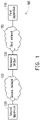
- FIG. 1 is a schematic view of a network system according to an embodiment of the disclosure.
- a network system 100 includes a first apparatus 110, a second apparatus 120, and a network bridge 130.
- the first apparatus 110 is coupled to a first network 112
- the second apparatus 120 is coupled to a second network 122
- the network bridge 130 is coupled between the first network 112 and the second network 122, wherein a domain of the first network 112 is different from a domain of the network bridge 130.
- an IP address of the first apparatus 110 and an IP address of the network bridge 130 belong to different domain names.
- the first network 112 and the second network 122 may belong to the same domain or different domains, which should not be construed as a limitation in the disclosure.
- the network bridge 130 is a network bridge which may integrate different transmission entities and allow connections under different network standards, including but not limited to, the connection between two Ethernet networks or the connection between an Ethernet network and a Token Ring. According to the present embodiment, the network bridge 130 forwards a data packet sent from the first apparatus 110 in the first network 112 to the second apparatus 120 in the second network 122.
- the network bridge 130 receives a first packet sent from the first apparatus 110 in the different domain and determines whether an IP address in a destination IP address field of the first packet is the same as the IP address of the network bridge 130. If the destination IP address of the first packet and the IP address of the network bridge 130 are the same, the IP address of the first apparatus 110 is replaced with a virtual IP address in a source IP address field of the first packet, so that the network bridge 130 would consider that the first packet is sent by a host in the same domain.
- the virtual IP address and the IP address of the network bridge 130 belong to the same domain.
- the network bridge 130 directly forwards the first packet to the second apparatus 120 located in the second network 122. Embodiments of the disclosure are described in detail hereinafter.
- the first apparatus 110 and the second apparatus 120 are physical hosts, such as a desktop computer, a notebook computer, a tablet PC, an ultra-mobile PC (UMPC), a personal digital assistant (PDA), a smart phone, a mobile phone, a PlayStation Portable (PSP), a work station, a server, or the like, which should however not be construed as a limitation in the disclosure.
- one of the first apparatus 110 and the second apparatus 120 may be capable of performing a function of a routing packet, e.g., a router, a gateway, a cable modem (CM), which should however not be construed as a limitation in the disclosure.
- a routing packet e.g., a router, a gateway, a cable modem (CM)
- the first network 112 and the second network 122 may be cable networks, wireless networks, or Internet, which is not limited in the disclosure.
- one of the first network 112 and the second network 122 is a cable network, using a hybrid fiber-coaxial (HFC) as a transmission medium, and the other one is a cable network, using optical fiber as the transmission medium, an Internet, or a wireless local area network (WLAN).
- HFC hybrid fiber-coaxial
- WLAN wireless local area network
- the first apparatus 110 is, for instance, a mobile apparatus; the second apparatus 120 is, for instance, a gateway; and the network bridge 130 is, for instance, a CM.
- the network bridge 130 is connected to the second apparatus 120 through HFC and is connected to the first apparatus 110 through a cable or in a wireless manner.
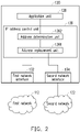
- FIG. 2 is a schematic block view of a network bridge according to an embodiment of the disclosure.
- FIG. 3 is a flow chart of a network management method according to an embodiment of the disclosure.
- the management method shown in FIG. 3 is applicable to the embodiments shown in FIG. 1 and FIG. 2 , and the network bridge and the way to conduct the network management method provided in an embodiment of the disclosure are further elaborated hereinafter.
- the network bridge 130 includes a first network interface 132, a second network interface 134, an IP address control unit 136, and an application unit 138.
- the application unit 138 is coupled to the IP address control unit 136
- the IP address control unit 136 is coupled to the application unit 138, the first network interface 132, and the second network interface 134.
- the IP address control unit 136 includes an address determination unit 1361 and an address replacement unit 1362.
- the network bridge 130 transmits data to the first apparatus 110 in the first network 112 and the second apparatus 120 in the second network 122 via the first network interface 132 and the second network interface 134, respectively.
- the first network interface 132 and the second network interface 134 may be but not limited to cable or wireless network interface cards, for instance.
- the first network interface 132 and the second network interface 134 are connected to the first network 112 and the second network 122, respectively, so as to access the data packets in the first network 112 or the second network 122.
- the application unit 138 and the IP address control unit 136 are, for instance, central processing units (CPU), microprocessors, application specific integrated Circuits (ASIC), programmable logic devices (PLD), other apparatuses having computing capabilities, or a combination of the aforesaid apparatuses, which should not be construed as a limitation in the disclosure.
- the address determination unit 1361 and the address replacement unit 1362 may be implemented by software or hardware, e.g., in form of circuits. Alternatively, if the IP address control unit 136 is a processor, it could be implemented by the execution of an address determination command and an address replacement command.
- the application unit 138 is configured to execute an application program, so as to bridge the first network 112 and the second network 122.
- the application program is, for instance, a network bridge management system, a network bridge communication protocol, or another upper-level application software.
- the IP address control unit 136 is configured to receive or transmit the data packet through the first network interface 132 or the second network interface 134 and analyze a received frame, the destination IP address of the data packet, or a destination media access control (MAC) address of the data packet. According to the port state of the network bridge 130, the IP address control unit 136 determines whether to filter or forward the data packet.
- MAC media access control
- step S202 the first apparatus 110 sends the first packet to the network bridge 130; next, in step S204, the IP address control unit 136 receives through the first network interface 132 the first packet sent from the first apparatus 110.
- step S206 the address determination unit 1361 of the IP address control unit 136 determines whether the IP address in the destination IP address field of the first packet is the IP address of the network bridge 130. If the address determination unit 1361 determines that the destination IP address in the first packet and the IP address of the network bridge 130 are the same, step S208 is performed; otherwise, step S218 is carried out.
- the IP address control unit 136 records the source IP address of the first packet and sets a client IP address of the network bridge 130 to the source IP address of the first packet. Particularly, the IP address control unit 136 not only records the IP address of the first apparatus 110 in the source IP address field of the first packet but also records an initial value of a destination MAC address field of the first packet and sets a remote MAC address of the network bridge 130 to the initial value of the destination MAC address field of the first packet. In other embodiments, it is noted that the IP address control unit 136 may omit the step of recording the destination MAC address of the first packet.
- step S210 the address replacement unit 1362 replaces the IP address of the first apparatus 110 with a virtual IP address in the source IP address field of the first packet, wherein the virtual IP address serving as a replacement and the IP address of the network bridge 130 belong to the same domain.
- the address replacement unit 1362 can also set the destination MAC address field of the first packet to the MAC address of the network bridge 130.
- step S212 after the source IP address and the destination MAC address of the first packet are already set as the virtual IP address and the MAC address having the same domain as the network bridge 130 does, the IP address control unit 136 sends the first packet to the application unit 138, and the application unit 138 receives the replaced first packet from the IP address control unit 136 and processes the replaced first packet.
- the source IP address of the first packet is already changed to the IP address having the same domain as the network bridge 130 does; therefore, direct communications with the network bridge 130 are possible, and the application unit 138 is able to perform operations according to the data in the first packet.
- the first apparatus 110 provided in the present embodiment can manage the network bridge 130.
- step S214 the application unit 138 returns the second packet.
- the second packet is sent to the IP address control unit 136 first.
- the destination IP address of the second packet sent from the application unit 138 is the virtual IP address in step S210.
- the application unit 138 considers the host sending the first packet and the network bridge 130 belong to the same domain; hence, the destination IP address of the second packet is the virtual IP address, and the destination MAC address of the second packet is the MAC address of the first apparatus 110, for instance.
- the destination IP address field of the second packet is set to the IP address of the client, i.e., the virtual IP address is replaced with the IP address of the first apparatus 110 in the destination IP address field of the second packet.
- the second apparatus 120 is capable of processing a communication protocol, such as a gateway (but not limited thereto).
- the address replacement unit 1362 could further change the source MAC address in the second packet from the MAC address of the network bridge 130 back to the MAC address of the second apparatus 120, i.e., the original destination MAC address in the first packet.
- the IP address control unit 136 may not change the source MAC address in the second packet, so that the source MAC address in the second packet continues to be the MAC address of the network bridge 130.
- the source MAC address field of the second packet may contains the MAC address of the network bridge 130 or the MAC address of the second apparatus 120 in the second network 122.
- step S216 the IP address control unit 136 returns the second packet to the first apparatus 110 through the first network interface 132, and step S220 is then performed to complete the communication.
- step S218 is performed, and the IP address control unit 136 forwards the first packet to the second apparatus 120 via the second network interface 134.
- the first apparatus belonging to a domain different from that of the network bridge sends the first packet to the network bridge, and the network bridge determines whether the destination IP address of the first packet is the same as the IP address of the network bridge. If these addresses are the same, the network bridge replaces the source IP address and the destination MAC address of the first packet with the virtual IP address and the MAC address having the same domain as the network bridge does, respectively. Thereby, the application unit of the network bridge may perform settings according to the replaced first packet, and the network bridge returns the second packet to the first apparatus, so as to complete the communication with the first apparatus. Since the network bridge may automatically change the source IP address and the destination MAC address of the first packet, the network bridge and the network management method provided in one or more embodiments of the disclosure contribute to the simplification of the user's operation or the process of managing the network bridge.
Landscapes
- Engineering & Computer Science (AREA)
- Computer Networks & Wireless Communication (AREA)
- Signal Processing (AREA)
- Computer Security & Cryptography (AREA)
- Data Exchanges In Wide-Area Networks (AREA)
- Small-Scale Networks (AREA)
Claims (14)
- Netzwerkbrücke (130), umfassend eine erste Netzwerkschnittstelle (132), die konfiguriert ist, um ein erstes Paket zu empfangen, gesendet von einer ersten Vorrichtung (110), verbunden mit einem ersten Netzwerk (112), umfassend:
eine IP-Adressensteuereinheit (136), umfassend:eine Adressenbestimmungseinheit (1361), die konfiguriert ist, um zu bestimmen, ob sich eine IP-Adresse der Netzwerkbrücke (130) in einem Ziel-IP-Adressenfeld des ersten Pakets befindet, wobei sich eine Domäne des ersten Netzwerks (112) von einer Domäne der Netzwerkbrücke (130) unterscheidet; undeine Adressenersatzeinheit (1362), die konfiguriert ist, um eine IP-Adresse der ersten Vorrichtung (110) in einem Quell-IP-Adressenfeld des ersten Pakets durch eine virtuelle IP-Adresse zu ersetzen, um ein ersetztes erstes Paket nur dann zu erhalten, wenn sich die IP-Adresse der Netzwerkbrücke (130) in dem Ziel-IP-Adressenfeld des ersten Pakets befindet, wobei die virtuelle IP-Adresse und die IP-Adresse der Netzwerkbrücke (130) zu derselben Domäne gehören; undeine Anwendungseinheit (138), die konfiguriert ist, um das ersetzte erste Paket von der IP-Adressensteuereinheit (136) zu empfangen und ein Anwendungsprogramm entsprechend den Daten in dem ersetzten ersten Paket ausführt. - Netzwerkbrücke (130) nach Anspruch 1, wobei die Anwendungseinheit (138) ein zweites Paket an die Adressenersatzeinheit (1362) zurückgibt, und wenn die Adressenersatzeinheit (1362) das zweite Paket empfängt, ersetzt die Adressenersatzeinheit (1362) die virtuelle IP-Adresse in einem Ziel-IP-Adressenfeld des zweiten Pakets durch die IP-Adresse der ersten Vorrichtung (110).
- Netzwerkbrücke (130) nach Anspruch 2, wobei ein Quell-Media-Access-Control-Adressenfeld des zweiten Pakets ein Media-Access-Control-Adresse der Netzwerkbrücke (130) oder eine Media-Access-Control-Adresse einer zweiten Vorrichtung (120) in einem zweiten Netzwerk (122) enthält.
- Netzbrücke (130) nach Anspruch 3, ferner umfassend:
eine zweite Netzwerkschnittstelle (134), die konfiguriert ist, um Daten an die zweite Vorrichtung (120) in dem zweiten Netzwerk (122) zu übertragen. - Netzwerkbrücke (130) nach Anspruch 1 oder 2, wobei die IP-Adressensteuereinheit (136) ferner konfiguriert ist, um die IP-Adresse der ersten Vorrichtung (110) in dem Quell-IP-Adressenfeld des ersten Pakets aufzuzeichnen, bevor die IP-Adresse der ersten Vorrichtung (110) in dem Quell-IP-Adressenfeld des ersten Pakets durch die virtuelle IP-Adresse ersetzt wird.
- Netzwerkbrücke (130) nach Anspruch 1 oder 2 oder 5, wobei, wenn die Adressenbestimmungseinheit (1361) bestimmt, dass das Ziel-IP-Adressenfeld des ersten Pakets nicht die IP-Adresse der Netzwerkbrücke (130) enthält, sondern eine IP-Adresse einer zweiten Vorrichtung (120) enthält, die Netzwerkbrücke (130) das erste Paket an die zweite Vorrichtung (120) weiterleitet, wobei sich die zweite Vorrichtung (120) in einem zweiten Netzwerk (122) befindet.
- Netzwerkbrücke (130) des Anspruchs 1 oder 2 oder 5 oder 6, wobei, wenn die Adressenbestimmungseinheit (1361) das Ziel-IP-Adressenfeld des ersten Pakets bestimmt, die IP-Adresse der Netzwerkbrücke (130) enthält, die Adressenersatzeinheit (1362) ein Ziel-Media-Access-Control-Adressenfeld des ersten Pakets zu einer Media-Access-Control-Adresse der Netzwerkbrücke (130) setzt.
- Netzwerkbrücke (130) nach Anspruch 7, wobei die IP-Adressensteuereinheit (136) ferner einen Wert des Ziel-Media-Access-Control-Adressenfeldes des ersten Pakets aufzeichnet.
- Netzwerkbrücke (130) des Anspruchs 1 oder 2 oder 5 oder 6 oder 7, wobei die erste Vorrichtung (110) eine mobile Vorrichtung umfasst, die zweite Vorrichtung (120) ein Gateway umfasst, die Netzwerkbrücke (130) ein Kabelmodem umfasst und die Netzwerkbrücke (130) über ein Koaxialkabel mit der zweiten Vorrichtung (120) verbunden ist und über ein Kabel oder drahtlos mit der ersten Vorrichtung (110) verbunden ist.
- Verwaltungsverfahren einer Netzwerkbrücke (130), die ein erstes Paket empfängt, das von einer ersten Vorrichtung (110) gesendet wird, verbunden mit einem ersten Netzwerk (112), umfasst:Bestimmen, ob sich eine IP-Adresse der Netzwerkbrücke (130) in einem Ziel-IP-Adressenfeld des ersten Pakets befindet, wobei sich eine Domäne des ersten Netzwerks (112) von einer Domäne der Netzwerkbrücke (130) unterscheidet; undnur wenn sich die IP-Adresse der Netzwerkbrücke (130) in dem Ziel-IP-Adressenfeld des ersten Pakets befindet, Ersetzen einer IP-Adresse der ersten Vorrichtung (110) in einem Quell-IP-Adressenfeld des ersten Pakets durch eine virtuelle IP-Adresse, um ein ersetztes erstes Paket zu erhalten, und Ausführen eines Anwendungsprogramms gemäß den Daten in dem ersetzten ersten Paket; wobei die virtuelle IP-Adresse und die IP-Adresse der Netzwerkbrücke (130) zu derselben Domäne gehören.
- Netzwerkverwaltungsverfahren nach Anspruch 10, wenn das Ziel-IP-Adressenfeld des ersten Pakets nicht die IP-Adresse der Netzwerkbrücke (130), sondern eine IP-Adresse einer zweiten Vorrichtung (120) enthält, leitet das erste Paket an die zweite Vorrichtung (120) weiter, wobei sich die zweite Vorrichtung (120) in einem zweiten Netzwerk (122) befindet.
- Netzwerkverwaltungsverfahren nach Anspruch 10 oder 11, wobei der Schritt zum Ersetzen der IP-Adresse der ersten Vorrichtung (110) durch die virtuelle IP-Adresse, wenn die IP-Adresse der Netzwerkbrücke (130) in dem Ziel-IP-Adressenfeld des ersten Pakets sich befindet, ferner umfasst:
Setzen eines Ziel-Media-Access-Control-Felds des ersten Pakets auf eine Media-Access-Control-Adresse der Netzwerkbrücke (130). - Netzwerkverwaltungsverfahren nach Anspruch 12, wobei der Schritt zum Setzen des Ziel-Media-Access-Control-Felds des ersten Pakets auf die Media-Access-Control-Adresse der Netzwerkbrücke (130), umfassend:
Aufzeichnen eines Werts des Ziel-Media-Access-Control-Adressenfeld des ersten Pakets. - Netzwerkverwaltungsverfahren nach Anspruch 12, wobei die Netzwerkbrücke (130) ein zweites Paket an das erste Netzwerk (112) zurückgibt und die virtuelle IP-Adresse im Ziel-IP-Adressenfeld des zweiten Pakets durch die IP-Adresse der ersten Vorrichtung (110) ersetzt, wobei ein Quell-Media-Access-Control-Adressenfeld des zweiten Pakets mit der Media-Access-Control-Adresse der Netzwerkbrücke (130) oder einer Medien-Access-Control-Adresse einer zweiten Vorrichtung (120) in einem zweiten Netzwerk (122) gefüllt ist.
Applications Claiming Priority (1)
| Application Number | Priority Date | Filing Date | Title |
|---|---|---|---|
| TW107109350A TWI713328B (zh) | 2018-03-19 | 2018-03-19 | 橋接器及網路的管理方法 |
Publications (2)
| Publication Number | Publication Date |
|---|---|
| EP3544266A1 EP3544266A1 (de) | 2019-09-25 |
| EP3544266B1 true EP3544266B1 (de) | 2022-05-04 |
Family
ID=65861202
Family Applications (1)
| Application Number | Title | Priority Date | Filing Date |
|---|---|---|---|
| EP19162079.8A Active EP3544266B1 (de) | 2018-03-19 | 2019-03-12 | Netzwerkbrücke und netzwerkverwaltungsverfahren |
Country Status (6)
| Country | Link |
|---|---|
| US (1) | US20190288872A1 (de) |
| EP (1) | EP3544266B1 (de) |
| JP (1) | JP6975736B2 (de) |
| KR (1) | KR102109174B1 (de) |
| CN (1) | CN110289979B (de) |
| TW (1) | TWI713328B (de) |
Families Citing this family (1)
| Publication number | Priority date | Publication date | Assignee | Title |
|---|---|---|---|---|
| CN114448750B (zh) * | 2022-01-19 | 2024-06-04 | 深圳市联洲国际技术有限公司 | 一种纯网桥模式的通信方法、装置、设备及介质 |
Family Cites Families (16)
| Publication number | Priority date | Publication date | Assignee | Title |
|---|---|---|---|---|
| US5280480A (en) * | 1991-02-21 | 1994-01-18 | International Business Machines Corporation | Source routing transparent bridge |
| US6831917B1 (en) * | 2000-05-10 | 2004-12-14 | Cisco Technology, Inc. | Network address translation for multicast virtual sourcing |
| WO2006072052A2 (en) * | 2004-12-31 | 2006-07-06 | Anonymizer, Inc. | System for protecting identity in a network environment |
| US9577842B2 (en) * | 2008-02-25 | 2017-02-21 | Cisco Technology, Inc. | Shared L2 bridging domains for L3 virtual networks |
| CN101478505B (zh) * | 2009-01-23 | 2011-09-07 | 建汉科技股份有限公司 | 不同私有网络的网络装置间建立网络系统及网络联机方法 |
| JP4843116B1 (ja) * | 2011-08-22 | 2011-12-21 | 株式会社Into | ネットワークゲートウェイ装置 |
| US9756682B2 (en) * | 2012-02-06 | 2017-09-05 | Aruba Networks, Inc. | Method and system for partitioning wireless local area network |
| TWI482469B (zh) * | 2012-05-23 | 2015-04-21 | Gemtek Technology Co Ltd | 路由裝置 |
| JP6036464B2 (ja) * | 2013-03-26 | 2016-11-30 | 富士通株式会社 | プログラム、診断方法及び診断システム |
| EP3092751A4 (de) * | 2014-01-06 | 2017-10-18 | Samsung Electronics Co., Ltd. | Verfahren und vorrichtung zur vermittlung von paketübertragungen und zur aktualisierung der netzwerkadresseninformation in einem kommunikationssystem |
| KR102139793B1 (ko) * | 2014-01-06 | 2020-07-31 | 삼성전자주식회사 | 무선 통신 시스템에서 패킷 송신을 중계하기 위한 방법 및 장치 |
| KR102163903B1 (ko) * | 2014-01-06 | 2020-10-12 | 삼성전자주식회사 | 유/무선 브리지를 이용하는 통신 시스템에서 네트워크 주소 정보를 업데이트하는 방법 및 장치 |
| CN104468389B (zh) * | 2014-11-27 | 2018-02-06 | 华为技术有限公司 | 消息的处理方法、服务器和服务器系统 |
| US10701707B2 (en) * | 2017-03-28 | 2020-06-30 | Arris Enterprises Llc | Allocation of wireless channels for preferred stations |
| IT201700093693A1 (it) * | 2017-08-14 | 2019-02-14 | St Microelectronics Srl | Procedimento per trasmettere almeno un pacchetto di dati ip, relativo sistema e prodotto informatico |
| CN107809386B (zh) * | 2017-11-15 | 2020-03-27 | 锐捷网络股份有限公司 | Ip地址转换方法、路由设备和通信系统 |
-
2018
- 2018-03-19 TW TW107109350A patent/TWI713328B/zh active
- 2018-11-27 KR KR1020180148679A patent/KR102109174B1/ko active Active
-
2019
- 2019-01-18 CN CN201910047467.4A patent/CN110289979B/zh active Active
- 2019-02-18 JP JP2019026452A patent/JP6975736B2/ja active Active
- 2019-02-20 US US16/280,919 patent/US20190288872A1/en not_active Abandoned
- 2019-03-12 EP EP19162079.8A patent/EP3544266B1/de active Active
Also Published As
| Publication number | Publication date |
|---|---|
| JP6975736B2 (ja) | 2021-12-01 |
| US20190288872A1 (en) | 2019-09-19 |
| EP3544266A1 (de) | 2019-09-25 |
| CN110289979B (zh) | 2022-02-01 |
| CN110289979A (zh) | 2019-09-27 |
| TWI713328B (zh) | 2020-12-11 |
| TW201939928A (zh) | 2019-10-01 |
| KR102109174B1 (ko) | 2020-05-12 |
| JP2019165436A (ja) | 2019-09-26 |
Similar Documents
| Publication | Publication Date | Title |
|---|---|---|
| US11711242B2 (en) | Secure SD-WAN port information distribution | |
| US9338093B2 (en) | Mobile phone docking station VPNs | |
| RU2357281C2 (ru) | Виртуальная сеть вещания для междоменной связи | |
| US9596211B2 (en) | Cloud based customer premises equipment | |
| CN106789526B (zh) | 多系统网络连接的方法及装置 | |
| CN109450905B (zh) | 传输数据的方法和装置及系统 | |
| CN114080054A (zh) | 一种pdu会话建立方法、终端设备和芯片系统 | |
| US20250379845A1 (en) | Method for Configuring Network Address Translation Gateway and Cloud Management Platform | |
| CN114025009B (zh) | 转发请求的方法、系统、代理服务器和装置 | |
| CN106416146B (zh) | 通信装置、通信方法和通信系统 | |
| US11424961B2 (en) | Exporting the device sharing attribute for host devices from a wireless controller to a switch | |
| WO2012075768A1 (zh) | 身份位置分离网络的监听方法和系统 | |
| EP3544266A1 (de) | Netzwerkbrücke und netzwerkverwaltungsverfahren | |
| JP2014212507A (ja) | 通信基地局およびその制御方法 | |
| CN109274590B (zh) | 移动宽带路由器的远程管理方法及电路 | |
| EP4595406A1 (de) | System und verfahren zur erzeugung eines zugangsnetzes für private dienste | |
| CN112994928A (zh) | 一种虚拟机的管理方法、装置及系统 | |
| RU2635216C1 (ru) | Способ маршрутизации IP-пакетов при использовании VPLS совместно с DHCP в сети с коммутацией пакетов | |
| CN115883256B (zh) | 基于加密隧道的数据传输方法、装置及存储介质 | |
| CN119788602B (zh) | Vpn网关流量转发方法、装置、电子设备及存储介质 | |
| KR101996588B1 (ko) | Arp 프로토콜을 지원하는 분리망 연계장치 및 그 제어방법 | |
| WO2025051027A1 (zh) | 流量策略确定方法、电子设备及存储介质 | |
| CN117596230A (zh) | 网络连接方法、装置、设备及存储介质 | |
| CN117459965A (zh) | 用于通过住宅网关进行的网络接入的单独pfcp会话模型 | |
| WO2019152668A1 (en) | Application service virtual circuit |
Legal Events
| Date | Code | Title | Description |
|---|---|---|---|
| PUAI | Public reference made under article 153(3) epc to a published international application that has entered the european phase |
Free format text: ORIGINAL CODE: 0009012 |
|
| STAA | Information on the status of an ep patent application or granted ep patent |
Free format text: STATUS: THE APPLICATION HAS BEEN PUBLISHED |
|
| AK | Designated contracting states |
Kind code of ref document: A1 Designated state(s): AL AT BE BG CH CY CZ DE DK EE ES FI FR GB GR HR HU IE IS IT LI LT LU LV MC MK MT NL NO PL PT RO RS SE SI SK SM TR |
|
| AX | Request for extension of the european patent |
Extension state: BA ME |
|
| STAA | Information on the status of an ep patent application or granted ep patent |
Free format text: STATUS: REQUEST FOR EXAMINATION WAS MADE |
|
| 17P | Request for examination filed |
Effective date: 20200311 |
|
| RBV | Designated contracting states (corrected) |
Designated state(s): AL AT BE BG CH CY CZ DE DK EE ES FI FR GB GR HR HU IE IS IT LI LT LU LV MC MK MT NL NO PL PT RO RS SE SI SK SM TR |
|
| STAA | Information on the status of an ep patent application or granted ep patent |
Free format text: STATUS: EXAMINATION IS IN PROGRESS |
|
| 17Q | First examination report despatched |
Effective date: 20200814 |
|
| GRAP | Despatch of communication of intention to grant a patent |
Free format text: ORIGINAL CODE: EPIDOSNIGR1 |
|
| STAA | Information on the status of an ep patent application or granted ep patent |
Free format text: STATUS: GRANT OF PATENT IS INTENDED |
|
| INTG | Intention to grant announced |
Effective date: 20211020 |
|
| GRAS | Grant fee paid |
Free format text: ORIGINAL CODE: EPIDOSNIGR3 |
|
| GRAA | (expected) grant |
Free format text: ORIGINAL CODE: 0009210 |
|
| STAA | Information on the status of an ep patent application or granted ep patent |
Free format text: STATUS: THE PATENT HAS BEEN GRANTED |
|
| AK | Designated contracting states |
Kind code of ref document: B1 Designated state(s): AL AT BE BG CH CY CZ DE DK EE ES FI FR GB GR HR HU IE IS IT LI LT LU LV MC MK MT NL NO PL PT RO RS SE SI SK SM TR |
|
| REG | Reference to a national code |
Ref country code: GB Ref legal event code: FG4D |
|
| REG | Reference to a national code |
Ref country code: CH Ref legal event code: EP |
|
| REG | Reference to a national code |
Ref country code: AT Ref legal event code: REF Ref document number: 1490383 Country of ref document: AT Kind code of ref document: T Effective date: 20220515 |
|
| REG | Reference to a national code |
Ref country code: DE Ref legal event code: R096 Ref document number: 602019014312 Country of ref document: DE |
|
| REG | Reference to a national code |
Ref country code: IE Ref legal event code: FG4D |
|
| REG | Reference to a national code |
Ref country code: LT Ref legal event code: MG9D |
|
| REG | Reference to a national code |
Ref country code: NL Ref legal event code: MP Effective date: 20220504 |
|
| REG | Reference to a national code |
Ref country code: AT Ref legal event code: MK05 Ref document number: 1490383 Country of ref document: AT Kind code of ref document: T Effective date: 20220504 |
|
| PG25 | Lapsed in a contracting state [announced via postgrant information from national office to epo] |
Ref country code: SE Free format text: LAPSE BECAUSE OF FAILURE TO SUBMIT A TRANSLATION OF THE DESCRIPTION OR TO PAY THE FEE WITHIN THE PRESCRIBED TIME-LIMIT Effective date: 20220504 Ref country code: PT Free format text: LAPSE BECAUSE OF FAILURE TO SUBMIT A TRANSLATION OF THE DESCRIPTION OR TO PAY THE FEE WITHIN THE PRESCRIBED TIME-LIMIT Effective date: 20220905 Ref country code: NO Free format text: LAPSE BECAUSE OF FAILURE TO SUBMIT A TRANSLATION OF THE DESCRIPTION OR TO PAY THE FEE WITHIN THE PRESCRIBED TIME-LIMIT Effective date: 20220804 Ref country code: NL Free format text: LAPSE BECAUSE OF FAILURE TO SUBMIT A TRANSLATION OF THE DESCRIPTION OR TO PAY THE FEE WITHIN THE PRESCRIBED TIME-LIMIT Effective date: 20220504 Ref country code: LT Free format text: LAPSE BECAUSE OF FAILURE TO SUBMIT A TRANSLATION OF THE DESCRIPTION OR TO PAY THE FEE WITHIN THE PRESCRIBED TIME-LIMIT Effective date: 20220504 Ref country code: HR Free format text: LAPSE BECAUSE OF FAILURE TO SUBMIT A TRANSLATION OF THE DESCRIPTION OR TO PAY THE FEE WITHIN THE PRESCRIBED TIME-LIMIT Effective date: 20220504 Ref country code: GR Free format text: LAPSE BECAUSE OF FAILURE TO SUBMIT A TRANSLATION OF THE DESCRIPTION OR TO PAY THE FEE WITHIN THE PRESCRIBED TIME-LIMIT Effective date: 20220805 Ref country code: FI Free format text: LAPSE BECAUSE OF FAILURE TO SUBMIT A TRANSLATION OF THE DESCRIPTION OR TO PAY THE FEE WITHIN THE PRESCRIBED TIME-LIMIT Effective date: 20220504 Ref country code: ES Free format text: LAPSE BECAUSE OF FAILURE TO SUBMIT A TRANSLATION OF THE DESCRIPTION OR TO PAY THE FEE WITHIN THE PRESCRIBED TIME-LIMIT Effective date: 20220504 Ref country code: BG Free format text: LAPSE BECAUSE OF FAILURE TO SUBMIT A TRANSLATION OF THE DESCRIPTION OR TO PAY THE FEE WITHIN THE PRESCRIBED TIME-LIMIT Effective date: 20220804 Ref country code: AT Free format text: LAPSE BECAUSE OF FAILURE TO SUBMIT A TRANSLATION OF THE DESCRIPTION OR TO PAY THE FEE WITHIN THE PRESCRIBED TIME-LIMIT Effective date: 20220504 |
|
| PG25 | Lapsed in a contracting state [announced via postgrant information from national office to epo] |
Ref country code: RS Free format text: LAPSE BECAUSE OF FAILURE TO SUBMIT A TRANSLATION OF THE DESCRIPTION OR TO PAY THE FEE WITHIN THE PRESCRIBED TIME-LIMIT Effective date: 20220504 Ref country code: PL Free format text: LAPSE BECAUSE OF FAILURE TO SUBMIT A TRANSLATION OF THE DESCRIPTION OR TO PAY THE FEE WITHIN THE PRESCRIBED TIME-LIMIT Effective date: 20220504 Ref country code: LV Free format text: LAPSE BECAUSE OF FAILURE TO SUBMIT A TRANSLATION OF THE DESCRIPTION OR TO PAY THE FEE WITHIN THE PRESCRIBED TIME-LIMIT Effective date: 20220504 Ref country code: IS Free format text: LAPSE BECAUSE OF FAILURE TO SUBMIT A TRANSLATION OF THE DESCRIPTION OR TO PAY THE FEE WITHIN THE PRESCRIBED TIME-LIMIT Effective date: 20220904 |
|
| PG25 | Lapsed in a contracting state [announced via postgrant information from national office to epo] |
Ref country code: SM Free format text: LAPSE BECAUSE OF FAILURE TO SUBMIT A TRANSLATION OF THE DESCRIPTION OR TO PAY THE FEE WITHIN THE PRESCRIBED TIME-LIMIT Effective date: 20220504 Ref country code: SK Free format text: LAPSE BECAUSE OF FAILURE TO SUBMIT A TRANSLATION OF THE DESCRIPTION OR TO PAY THE FEE WITHIN THE PRESCRIBED TIME-LIMIT Effective date: 20220504 Ref country code: RO Free format text: LAPSE BECAUSE OF FAILURE TO SUBMIT A TRANSLATION OF THE DESCRIPTION OR TO PAY THE FEE WITHIN THE PRESCRIBED TIME-LIMIT Effective date: 20220504 Ref country code: EE Free format text: LAPSE BECAUSE OF FAILURE TO SUBMIT A TRANSLATION OF THE DESCRIPTION OR TO PAY THE FEE WITHIN THE PRESCRIBED TIME-LIMIT Effective date: 20220504 Ref country code: DK Free format text: LAPSE BECAUSE OF FAILURE TO SUBMIT A TRANSLATION OF THE DESCRIPTION OR TO PAY THE FEE WITHIN THE PRESCRIBED TIME-LIMIT Effective date: 20220504 Ref country code: CZ Free format text: LAPSE BECAUSE OF FAILURE TO SUBMIT A TRANSLATION OF THE DESCRIPTION OR TO PAY THE FEE WITHIN THE PRESCRIBED TIME-LIMIT Effective date: 20220504 |
|
| REG | Reference to a national code |
Ref country code: DE Ref legal event code: R097 Ref document number: 602019014312 Country of ref document: DE |
|
| PLBE | No opposition filed within time limit |
Free format text: ORIGINAL CODE: 0009261 |
|
| STAA | Information on the status of an ep patent application or granted ep patent |
Free format text: STATUS: NO OPPOSITION FILED WITHIN TIME LIMIT |
|
| PG25 | Lapsed in a contracting state [announced via postgrant information from national office to epo] |
Ref country code: AL Free format text: LAPSE BECAUSE OF FAILURE TO SUBMIT A TRANSLATION OF THE DESCRIPTION OR TO PAY THE FEE WITHIN THE PRESCRIBED TIME-LIMIT Effective date: 20220504 |
|
| 26N | No opposition filed |
Effective date: 20230207 |
|
| PG25 | Lapsed in a contracting state [announced via postgrant information from national office to epo] |
Ref country code: SI Free format text: LAPSE BECAUSE OF FAILURE TO SUBMIT A TRANSLATION OF THE DESCRIPTION OR TO PAY THE FEE WITHIN THE PRESCRIBED TIME-LIMIT Effective date: 20220504 |
|
| P01 | Opt-out of the competence of the unified patent court (upc) registered |
Effective date: 20230825 |
|
| PG25 | Lapsed in a contracting state [announced via postgrant information from national office to epo] |
Ref country code: MC Free format text: LAPSE BECAUSE OF FAILURE TO SUBMIT A TRANSLATION OF THE DESCRIPTION OR TO PAY THE FEE WITHIN THE PRESCRIBED TIME-LIMIT Effective date: 20220504 |
|
| GBPC | Gb: european patent ceased through non-payment of renewal fee |
Effective date: 20230312 |
|
| REG | Reference to a national code |
Ref country code: BE Ref legal event code: MM Effective date: 20230331 |
|
| PG25 | Lapsed in a contracting state [announced via postgrant information from national office to epo] |
Ref country code: LU Free format text: LAPSE BECAUSE OF NON-PAYMENT OF DUE FEES Effective date: 20230312 |
|
| REG | Reference to a national code |
Ref country code: IE Ref legal event code: MM4A |
|
| PG25 | Lapsed in a contracting state [announced via postgrant information from national office to epo] |
Ref country code: GB Free format text: LAPSE BECAUSE OF NON-PAYMENT OF DUE FEES Effective date: 20230312 |
|
| PG25 | Lapsed in a contracting state [announced via postgrant information from national office to epo] |
Ref country code: IE Free format text: LAPSE BECAUSE OF NON-PAYMENT OF DUE FEES Effective date: 20230312 Ref country code: GB Free format text: LAPSE BECAUSE OF NON-PAYMENT OF DUE FEES Effective date: 20230312 |
|
| PG25 | Lapsed in a contracting state [announced via postgrant information from national office to epo] |
Ref country code: BE Free format text: LAPSE BECAUSE OF NON-PAYMENT OF DUE FEES Effective date: 20230331 |
|
| PG25 | Lapsed in a contracting state [announced via postgrant information from national office to epo] |
Ref country code: BG Free format text: LAPSE BECAUSE OF FAILURE TO SUBMIT A TRANSLATION OF THE DESCRIPTION OR TO PAY THE FEE WITHIN THE PRESCRIBED TIME-LIMIT Effective date: 20220504 |
|
| PG25 | Lapsed in a contracting state [announced via postgrant information from national office to epo] |
Ref country code: BG Free format text: LAPSE BECAUSE OF FAILURE TO SUBMIT A TRANSLATION OF THE DESCRIPTION OR TO PAY THE FEE WITHIN THE PRESCRIBED TIME-LIMIT Effective date: 20220504 |
|
| PGFP | Annual fee paid to national office [announced via postgrant information from national office to epo] |
Ref country code: CH Payment date: 20250401 Year of fee payment: 7 |
|
| PG25 | Lapsed in a contracting state [announced via postgrant information from national office to epo] |
Ref country code: CY Free format text: LAPSE BECAUSE OF FAILURE TO SUBMIT A TRANSLATION OF THE DESCRIPTION OR TO PAY THE FEE WITHIN THE PRESCRIBED TIME-LIMIT; INVALID AB INITIO Effective date: 20190312 |
|
| PG25 | Lapsed in a contracting state [announced via postgrant information from national office to epo] |
Ref country code: HU Free format text: LAPSE BECAUSE OF FAILURE TO SUBMIT A TRANSLATION OF THE DESCRIPTION OR TO PAY THE FEE WITHIN THE PRESCRIBED TIME-LIMIT; INVALID AB INITIO Effective date: 20190312 |
|
| PG25 | Lapsed in a contracting state [announced via postgrant information from national office to epo] |
Ref country code: TR Free format text: LAPSE BECAUSE OF FAILURE TO SUBMIT A TRANSLATION OF THE DESCRIPTION OR TO PAY THE FEE WITHIN THE PRESCRIBED TIME-LIMIT Effective date: 20220504 |
|
| REG | Reference to a national code |
Ref country code: CH Ref legal event code: U11 Free format text: ST27 STATUS EVENT CODE: U-0-0-U10-U11 (AS PROVIDED BY THE NATIONAL OFFICE) Effective date: 20260401 |
|
| PGFP | Annual fee paid to national office [announced via postgrant information from national office to epo] |
Ref country code: DE Payment date: 20260108 Year of fee payment: 8 |
|
| PGFP | Annual fee paid to national office [announced via postgrant information from national office to epo] |
Ref country code: IT Payment date: 20260320 Year of fee payment: 8 |
|
| PGFP | Annual fee paid to national office [announced via postgrant information from national office to epo] |
Ref country code: FR Payment date: 20260102 Year of fee payment: 8 |