EP3544159A1 - Method for manufacturing rotary electric machine - Google Patents
Method for manufacturing rotary electric machine Download PDFInfo
- Publication number
- EP3544159A1 EP3544159A1 EP17872220.3A EP17872220A EP3544159A1 EP 3544159 A1 EP3544159 A1 EP 3544159A1 EP 17872220 A EP17872220 A EP 17872220A EP 3544159 A1 EP3544159 A1 EP 3544159A1
- Authority
- EP
- European Patent Office
- Prior art keywords
- coil end
- end portions
- stator
- interposed member
- manufacturing
- Prior art date
- Legal status (The legal status is an assumption and is not a legal conclusion. Google has not performed a legal analysis and makes no representation as to the accuracy of the status listed.)
- Granted
Links
Images




Classifications
-
- H—ELECTRICITY
- H02—GENERATION; CONVERSION OR DISTRIBUTION OF ELECTRIC POWER
- H02K—DYNAMO-ELECTRIC MACHINES
- H02K15/00—Processes or apparatus specially adapted for manufacturing, assembling, maintaining or repairing of dynamo-electric machines
- H02K15/30—Manufacture of winding connections
- H02K15/33—Connecting winding sections; Forming leads; Connecting leads to terminals
- H02K15/35—Form-wound windings
-
- H—ELECTRICITY
- H02—GENERATION; CONVERSION OR DISTRIBUTION OF ELECTRIC POWER
- H02K—DYNAMO-ELECTRIC MACHINES
- H02K3/00—Details of windings
- H02K3/32—Windings characterised by the shape, form or construction of the insulation
- H02K3/34—Windings characterised by the shape, form or construction of the insulation between conductors or between conductor and core, e.g. slot insulation
-
- B—PERFORMING OPERATIONS; TRANSPORTING
- B23—MACHINE TOOLS; METAL-WORKING NOT OTHERWISE PROVIDED FOR
- B23K—SOLDERING OR UNSOLDERING; WELDING; CLADDING OR PLATING BY SOLDERING OR WELDING; CUTTING BY APPLYING HEAT LOCALLY, e.g. FLAME CUTTING; WORKING BY LASER BEAM
- B23K31/00—Processes relevant to this subclass, specially adapted for particular articles or purposes, but not covered by any single one of main groups B23K1/00 - B23K28/00
- B23K31/02—Processes relevant to this subclass, specially adapted for particular articles or purposes, but not covered by any single one of main groups B23K1/00 - B23K28/00 relating to soldering or welding
-
- H—ELECTRICITY
- H02—GENERATION; CONVERSION OR DISTRIBUTION OF ELECTRIC POWER
- H02K—DYNAMO-ELECTRIC MACHINES
- H02K15/00—Processes or apparatus specially adapted for manufacturing, assembling, maintaining or repairing of dynamo-electric machines
- H02K15/04—Processes or apparatus specially adapted for manufacturing, assembling, maintaining or repairing of dynamo-electric machines of windings prior to their mounting into the machines
- H02K15/0414—Processes or apparatus specially adapted for manufacturing, assembling, maintaining or repairing of dynamo-electric machines of windings prior to their mounting into the machines the windings consisting of separate elements, e.g. bars, segments or half coils
-
- H—ELECTRICITY
- H02—GENERATION; CONVERSION OR DISTRIBUTION OF ELECTRIC POWER
- H02K—DYNAMO-ELECTRIC MACHINES
- H02K3/00—Details of windings
- H02K3/46—Fastening of windings on the stator or rotor structure
- H02K3/50—Fastening of winding heads, equalising connectors, or connections thereto
-
- B—PERFORMING OPERATIONS; TRANSPORTING
- B23—MACHINE TOOLS; METAL-WORKING NOT OTHERWISE PROVIDED FOR
- B23K—SOLDERING OR UNSOLDERING; WELDING; CLADDING OR PLATING BY SOLDERING OR WELDING; CUTTING BY APPLYING HEAT LOCALLY, e.g. FLAME CUTTING; WORKING BY LASER BEAM
- B23K2101/00—Articles made by soldering, welding or cutting
- B23K2101/36—Electric or electronic devices
Definitions
- the present invention relates to a method of manufacturing a rotary electric machine, and particularly to a method of manufacturing a rotary electric machine for driving a vehicle.
- PTL 1 discloses that with an inner-circumferential-side coil end portion 40a and an outer-circumferential-side coil end portion 40b covered above stator wiring 40, an annular insulating member 53 along the shape of a stator core 30 is disposed to protect the stator wiring 40 from damage due to heat such as sparks during welding.
- An object of the present invention is to suppress reduction of insulation reliability between stator coils.
- a method of manufacturing a rotary electric machine is a method of manufacturing a stator including an insulating member intervening between a plurality of coil end portions each protruding from a stator core, the method including: a first step of disposing an interposed member to cover part of the insulating member between the plurality of coil end portions; and a second step of welding part of each of the plurality of coil end portions.
- the method of manufacturing the rotary electric machine according to the present invention in which the interposed member includes a material containing fiber.
- the method of manufacturing the rotary electric machine according to the present invention in which the interposed member includes a film material.
- the method of manufacturing the rotary electric machine according to the present invention in which the interposed member is disposed between the insulating member and a jig that positions the plurality of coil end portions.
- the method of manufacturing the rotary electric machine according to the present invention in which the interposed member is formed annularly along a disposed direction of the plurality of coil end portions, the interposed member having a plurality of through holes formed for inserting any of the plurality of coil end portions into the plurality of through holes.
- the method of manufacturing the rotary electric machine according to the present invention in which the interposed member is disposed at a substantial center in space between every adjacent coil end portions in a circumferential direction of the stator core.
- FIG. 1 is a perspective view of a stator 100 of a rotary electric machine according to the present embodiment.
- Each stator coil 410 is inserted into a stator core 300.
- Each coil end portion 400 is a portion of the stator coil 410 protruding outside the stator core 300, and is a portion above a portion 401 formed obliquely to the axial direction.
- An insulating member 500 is disposed between each of the plurality of coil end portions 400 arrayed in the radial direction of the stator 100.
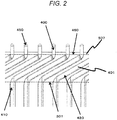
- FIG. 2 is an enlarged view of a dotted rectangular portion A around the coil end portions 400 illustrated in FIG. 1 .
- the lower dotted-line portion of the figure corresponds to an upper face portion 310 of the stator core 300.
- the stator coil 410 mainly made of copper is a flat coil having a rectangular cross section.
- the stator coil 410 is coated with enamel 420 around a portion housed in the stator core 300, that is, the portion 401.
- the enamel 420 is peeled off at the coil end portion 400 of the stator coil 410.
- Part of the coil end portion 400 mainly the leading end of the coil end portion 400, is welded for energization and a welded portion 450 is provided.
- the stator coil 410 is twisted and bent with the upper face portion 301 of the stator core 300 as a fulcrum.
- the insulating member 500 Since the insulating member 500 is to be used to insulate the enamel 420 of each adjacent stator coil 410, the insulating member 500 is formed to a position higher than an end 460 of the enamel 420.
- FIG. 3 is a perspective view of an interposed member 600 disposed at the coil end portions 400 of the stator 100.
- Each coil end portion 400 is welded in a state of the coil end portion 400 protruding from each through hole 650 provided through the interposed member 600.
- the interposed member 600 is disposed to cover part of the insulating member 500 before welding.
- FIG. 4 is an enlarged view around the interposed member 600 as viewed from an arrow direction of a dotted rectangular portion B of FIG. 3 .
- the interposed member 600 is disposed to cover part of the insulating member 500 between the coil end portions 400. Furthermore, the interposed member 600 is disposed at a substantially central portion 970 in space 960 between every adjacent coil end portions 400 in the circumferential direction 950 of the stator core 300.
- the interposed member 600 contains fiber as a main component that increases the thermal conductively. As a result, radiant heat due to welding and heat transfer transmitted through the stator coils 410 can be more absorbed, thereby enhancing a suppression effect on reduction of reliability due to dielectric breakdown.
- the interposed member 600 contains a film as a main component that increases the durability against breakage. As a result, there can be suppressed a possibility of breakage during disposing operation of the interposed member 600.
- FIG. 5 is an enlarged perspective view of the dotted rectangular portion A around the coil end portions 400 illustrated in FIG. 1 .
- Each coil end portion 400 includes a plurality of coil end portions 400a to 400d.
- the coil end portion 400a, the coil end portion 400b, the coil end portion 400c, and the coil end portion 400d are disposed in this order from space on the inner-diameter side 930 along space on the outer-diameter side 940 of the stator 100.
- the coil end portion 400a is coupled to the coil end portion 400b via a welded portion 450a.
- the coil end portion 400c is coupled to the coil end portion 400d via a welded portion 450b.
- FIG. 6 is an enlarged view of the coil end portions 400 after welding is applied to the stator 100 illustrated in FIG. 5 .
- a burnt portion 510 at the insulating member 500 is caused by radiant heat due to welding when, for example, the welded portion 450b is formed.
- the burnt portion 510 of the insulating member 500 can be visually checked after welding, so that completion of the welding can be determined. As a result, the burnt portion 510 of the insulating member 500 can be utilized for improving the yield.
- the presence of the interposed member 600 at the substantially central portion 970 between the coil end portions 400 can suppress burning of the insulating member 500 due to radiant heat.
- a burnt portion 610 of the interposed member 600 is caused by radiant heat due to welding.
- the disposition of the interposed member 600 between the coil end portions 400, particular at the substantially central portion 970 can prevent dielectric breakdown due to continuity between adjacent coil end portions 400 via the burnt portion 510.
- the interposed member 600 needs to be disposed at the substantially central portion 970 between the coil end portions 400, which has extremely less influence from radiant heat than near the coil end portions 400. As a result, the influence due to heat on the interposed member 600 is extremely reduced, whereby the durability increases to enable multiple usage.
- FIG. 9 is a top view of the interposed member 600.
- the interposed member 600 is formed annularly along the disposed direction of the coil end portions 400.
- the interposed member 600 has the plurality of through holes 650 formed for inserting any of the plurality of coil end portions 400 into the plurality of through holes 650.
- the through holes 650 each have space wider than the cross section of each of the plurality of coil end portions 400 to be able to easily house each of the plurality of coil end portions 400.
- FIG. 7 is an enlarged view of a jig 800 disposed at a stator 110 as illustrated in FIG. 5 .
- the jig 800 is installed on the upper face of an interposed member 600.
- a coil end portion 400b is brought close to the inner-diameter side 930 of the stator and positioned close to a coil end portion 400a by the jig 800.
- a coil end portion 400c is brought close to the outer-diameter side 940 of the stator and positioned close to a coil end portion 400d by the jig 800.
- the coil end portion 400a and the coil end portion 400b are coupled via a welded portion 450a, and the coil end portion 400c and the coil end portion 400d are coupled via a welded portion 450b.
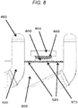
- FIG. 8 is an enlarged view after welding is applied to a stator 120 as illustrated in FIG. 7 .
- a burnt portion 520 of an insulating member 500 is caused by radiant heat due to welding.
- a burnt portion 620 of the interposed member 600 is caused due to heat transfer from the jig 800 generated by welding.
- the interposed member 600 is disposed at a substantially central portion 970 between coil end portions 400, in order to prevent dielectric breakdown due to continuity via the burnt portion 520.
- the interposed member 600 is disposed at the substantially central portion 970 between the coil end portions 400, which has extremely less influence from radiant heat than near the coil end portions 400.
Landscapes
- Engineering & Computer Science (AREA)
- Power Engineering (AREA)
- Manufacturing & Machinery (AREA)
- Mechanical Engineering (AREA)
- Manufacture Of Motors, Generators (AREA)
- Insulation, Fastening Of Motor, Generator Windings (AREA)
Abstract
Description
- The present invention relates to a method of manufacturing a rotary electric machine, and particularly to a method of manufacturing a rotary electric machine for driving a vehicle.
- Along with rapid popularization of hybrid vehicles and electric vehicles, it has been demanded in recent years to devise various methods of manufacturing rotary electric machines.
-
PTL 1 discloses that with an inner-circumferential-side coil end portion 40a and an outer-circumferential-side coil end portion 40b covered above stator wiring 40, an annular insulating member 53 along the shape of a stator core 30 is disposed to protect the stator wiring 40 from damage due to heat such as sparks during welding. - However, there has been a possibility that an insulating member for insulation between stator coils is burnt and carbonized during welding.
- PTL 1:
JP 2011-217511 A - An object of the present invention is to suppress reduction of insulation reliability between stator coils.
- A method of manufacturing a rotary electric machine according to the present invention is a method of manufacturing a stator including an insulating member intervening between a plurality of coil end portions each protruding from a stator core, the method including: a first step of disposing an interposed member to cover part of the insulating member between the plurality of coil end portions; and a second step of welding part of each of the plurality of coil end portions.
- Furthermore, the method of manufacturing the rotary electric machine according to the present invention, in which the interposed member includes a material containing fiber.
- Furthermore, the method of manufacturing the rotary electric machine according to the present invention, in which the interposed member includes a film material.
- Furthermore, the method of manufacturing the rotary electric machine according to the present invention, in which the interposed member is disposed between the insulating member and a jig that positions the plurality of coil end portions.
- Furthermore, the method of manufacturing the rotary electric machine according to the present invention, in which the interposed member is formed annularly along a disposed direction of the plurality of coil end portions, the interposed member having a plurality of through holes formed for inserting any of the plurality of coil end portions into the plurality of through holes.
- Furthermore, the method of manufacturing the rotary electric machine according to the present invention, in which the interposed member is disposed at a substantial center in space between every adjacent coil end portions in a circumferential direction of the stator core.
- According to the present invention, there can be suppressed reduction of insulation reliability between stator coils.
-
-
FIG. 1 is a perspective view of astator 100 of a rotary electric machine according to the present embodiment. -
FIG. 2 is an enlarged view of a dotted rectangular portion A aroundcoil end portions 400 illustrated inFIG. 1 . -
FIG. 3 is a perspective view of an interposedmember 600 disposed atcoil end portions 400 of thestator 100. -
FIG. 4 is an enlarged view around the interposedmember 600 as viewed from an arrow direction of a dotted rectangular portion B ofFIG. 3 . -
FIG. 5 is an enlarged perspective view of the dotted rectangular portion A around thecoil end portions 400 illustrated inFIG. 1 . -
FIG. 6 is an enlarged view of thecoil end portions 400 after welding is applied to thestator 100 illustrated inFIG. 5 . -
FIG. 7 is an enlarged view of ajig 800 disposed at a stator 110 as illustrated inFIG. 5 . -
FIG. 8 is an enlarged view after welding is applied to a stator 120 as illustrated inFIG. 7 . -
FIG. 9 is a top view of the interposedmember 600. - Embodiment of a method of manufacturing a rotary electric machine according to the present invention will be described with reference to the drawings.
-
FIG. 1 is a perspective view of astator 100 of a rotary electric machine according to the present embodiment. - Each
stator coil 410 is inserted into astator core 300. Eachcoil end portion 400 is a portion of thestator coil 410 protruding outside thestator core 300, and is a portion above aportion 401 formed obliquely to the axial direction. - An
insulating member 500 is disposed between each of the plurality ofcoil end portions 400 arrayed in the radial direction of thestator 100. -
FIG. 2 is an enlarged view of a dotted rectangular portion A around thecoil end portions 400 illustrated inFIG. 1 . Among the two dotted-line portions, the lower dotted-line portion of the figure corresponds to an upper face portion 310 of thestator core 300. - The
stator coil 410 mainly made of copper is a flat coil having a rectangular cross section. Thestator coil 410 is coated withenamel 420 around a portion housed in thestator core 300, that is, theportion 401. - The
enamel 420 is peeled off at thecoil end portion 400 of thestator coil 410. - Part of the
coil end portion 400, mainly the leading end of thecoil end portion 400, is welded for energization and awelded portion 450 is provided. - The
stator coil 410 is twisted and bent with theupper face portion 301 of thestator core 300 as a fulcrum. - Since the
insulating member 500 is to be used to insulate theenamel 420 of eachadjacent stator coil 410, theinsulating member 500 is formed to a position higher than anend 460 of theenamel 420. -
FIG. 3 is a perspective view of an interposedmember 600 disposed at thecoil end portions 400 of thestator 100. - Each
coil end portion 400 is welded in a state of thecoil end portion 400 protruding from each throughhole 650 provided through the interposedmember 600. The interposedmember 600 is disposed to cover part of the insulatingmember 500 before welding. -
FIG. 4 is an enlarged view around the interposedmember 600 as viewed from an arrow direction of a dotted rectangular portion B ofFIG. 3 . - The interposed
member 600 is disposed to cover part of theinsulating member 500 between thecoil end portions 400. Furthermore, the interposedmember 600 is disposed at a substantiallycentral portion 970 inspace 960 between every adjacentcoil end portions 400 in thecircumferential direction 950 of thestator core 300. - The interposed
member 600 contains fiber as a main component that increases the thermal conductively. As a result, radiant heat due to welding and heat transfer transmitted through thestator coils 410 can be more absorbed, thereby enhancing a suppression effect on reduction of reliability due to dielectric breakdown. - In addition, the interposed
member 600 contains a film as a main component that increases the durability against breakage. As a result, there can be suppressed a possibility of breakage during disposing operation of the interposedmember 600. -
FIG. 5 is an enlarged perspective view of the dotted rectangular portion A around thecoil end portions 400 illustrated inFIG. 1 . - Each
coil end portion 400 includes a plurality ofcoil end portions 400a to 400d. Thecoil end portion 400a, thecoil end portion 400b, thecoil end portion 400c, and thecoil end portion 400d are disposed in this order from space on the inner-diameter side 930 along space on the outer-diameter side 940 of thestator 100. - The
coil end portion 400a is coupled to thecoil end portion 400b via awelded portion 450a. Thecoil end portion 400c is coupled to thecoil end portion 400d via a weldedportion 450b. -
FIG. 6 is an enlarged view of thecoil end portions 400 after welding is applied to thestator 100 illustrated inFIG. 5 . - A
burnt portion 510 at the insulatingmember 500 is caused by radiant heat due to welding when, for example, thewelded portion 450b is formed. - Note that the
burnt portion 510 of theinsulating member 500 can be visually checked after welding, so that completion of the welding can be determined. As a result, theburnt portion 510 of the insulatingmember 500 can be utilized for improving the yield. - The presence of the interposed
member 600 at the substantiallycentral portion 970 between thecoil end portions 400 can suppress burning of theinsulating member 500 due to radiant heat. Aburnt portion 610 of the interposedmember 600 is caused by radiant heat due to welding. - The disposition of the interposed
member 600 between thecoil end portions 400, particular at the substantiallycentral portion 970 can prevent dielectric breakdown due to continuity between adjacentcoil end portions 400 via theburnt portion 510. - The interposed
member 600 needs to be disposed at the substantiallycentral portion 970 between thecoil end portions 400, which has extremely less influence from radiant heat than near thecoil end portions 400. As a result, the influence due to heat on the interposedmember 600 is extremely reduced, whereby the durability increases to enable multiple usage. -
FIG. 9 is a top view of the interposedmember 600. - The interposed
member 600 is formed annularly along the disposed direction of thecoil end portions 400. The interposedmember 600 has the plurality of throughholes 650 formed for inserting any of the plurality ofcoil end portions 400 into the plurality of throughholes 650. The throughholes 650 each have space wider than the cross section of each of the plurality ofcoil end portions 400 to be able to easily house each of the plurality ofcoil end portions 400. -
FIG. 7 is an enlarged view of ajig 800 disposed at a stator 110 as illustrated inFIG. 5 . - The
jig 800 is installed on the upper face of an interposedmember 600. Acoil end portion 400b is brought close to the inner-diameter side 930 of the stator and positioned close to acoil end portion 400a by thejig 800. - A
coil end portion 400c is brought close to the outer-diameter side 940 of the stator and positioned close to acoil end portion 400d by thejig 800. - The
coil end portion 400a and thecoil end portion 400b are coupled via a weldedportion 450a, and thecoil end portion 400c and thecoil end portion 400d are coupled via a weldedportion 450b. -
FIG. 8 is an enlarged view after welding is applied to a stator 120 as illustrated inFIG. 7 . - A
burnt portion 520 of an insulatingmember 500 is caused by radiant heat due to welding. Aburnt portion 620 of the interposedmember 600 is caused due to heat transfer from thejig 800 generated by welding. - The interposed
member 600 is disposed at a substantiallycentral portion 970 betweencoil end portions 400, in order to prevent dielectric breakdown due to continuity via theburnt portion 520. - The interposed
member 600 is disposed at the substantiallycentral portion 970 between thecoil end portions 400, which has extremely less influence from radiant heat than near thecoil end portions 400. - The use of the
jig 800 extremely reduces the influence due to heat on the interposedmember 600, so that the durability increases to enable multiple usage. Reference Signs List -
- 100
- stator
- 300
- stator core
- 301
- upper face portion
- 400
- coil end portion
- 400a
- coil end portion
- 400b
- coil end portion
- 400c
- coil end portion
- 400d
- coil end portion
- 401
- obliquely formed portion
- 410
- stator coil
- 420
- enamel
- 450
- welded portion
- 450a
- welded portion
- 450b
- welded portion
- 460
- end
- 500
- insulating member
- 510
- burnt portion
- 520
- burnt portion
- 600
- interposed member
- 620
- burnt portion
- 650
- through hole
- 930
- inner-diameter side
- 940
- outer-diameter side
- 950
- circumferential direction
- 960
- space
- 970
- substantially central portion
Claims (6)
- A method of manufacturing a stator including an insulating member intervening between a plurality of coil end portions each protruding from a stator core,
the method comprising:a first step of disposing an interposed member to cover part of the insulating member between the plurality of coil end portions; anda second step of welding part of each of the plurality of coil end portions. - The method of manufacturing the stator according to claim 1,
wherein the interposed member includes a material containing fiber. - The method of manufacturing the stator according to claim 1,
wherein the interposed member includes a film material. - The method of manufacturing the stator according to claim 1 or 2,
wherein the interposed member is disposed between the insulating member and a jig that positions the plurality of coil end portions. - The method of manufacturing the stator according to claim 1 or 2,
wherein the interposed member is formed annularly along a disposed direction of the plurality of coil end portions, the interposed member having a plurality of through holes formed for inserting any of the plurality of coil end portions into the plurality of through holes. - The method of manufacturing the stator according to any of claims 1 to 5,
wherein the interposed member is disposed at a substantial center in space between every adjacent coil end portions in a circumferential direction of the stator core.
Applications Claiming Priority (2)
| Application Number | Priority Date | Filing Date | Title |
|---|---|---|---|
| JP2016224634 | 2016-11-18 | ||
| PCT/JP2017/038334 WO2018092528A1 (en) | 2016-11-18 | 2017-10-24 | Method for manufacturing rotary electric machine |
Publications (3)
| Publication Number | Publication Date |
|---|---|
| EP3544159A1 true EP3544159A1 (en) | 2019-09-25 |
| EP3544159A4 EP3544159A4 (en) | 2020-06-24 |
| EP3544159B1 EP3544159B1 (en) | 2023-08-16 |
Family
ID=62145229
Family Applications (1)
| Application Number | Title | Priority Date | Filing Date |
|---|---|---|---|
| EP17872220.3A Active EP3544159B1 (en) | 2016-11-18 | 2017-10-24 | Method for manufacturing rotary electric machine |
Country Status (5)
| Country | Link |
|---|---|
| US (1) | US11387719B2 (en) |
| EP (1) | EP3544159B1 (en) |
| JP (1) | JP6725683B2 (en) |
| CN (1) | CN109923771B (en) |
| WO (1) | WO2018092528A1 (en) |
Cited By (1)
| Publication number | Priority date | Publication date | Assignee | Title |
|---|---|---|---|---|
| WO2021084180A1 (en) * | 2019-10-31 | 2021-05-06 | Nidec Psa Emotors | Device for cooling segmented electrical conductors |
Families Citing this family (5)
| Publication number | Priority date | Publication date | Assignee | Title |
|---|---|---|---|---|
| DE102018103100A1 (en) | 2017-07-04 | 2019-01-10 | Grob-Werke Gmbh & Co. Kg | Method and device for positioning and clamping wire ends for electrical machines |
| DE102018128920B4 (en) * | 2018-11-16 | 2025-01-30 | Gehring Technologies Gmbh + Co. Kg | Cover and device for simultaneously aligning and masking hairpins of a stator in preparation for a welding process and method for connecting upper ends of hairpins of a stator |
| JP7222945B2 (en) * | 2020-03-12 | 2023-02-15 | 株式会社アイシン | Stator manufacturing method for rotary electric machine |
| KR102744079B1 (en) * | 2020-03-17 | 2024-12-19 | 엘지마그나 이파워트레인 주식회사 | Stator |
| JP7646681B2 (en) * | 2020-08-20 | 2025-03-17 | 株式会社東芝 | Welding jig and manufacturing method for rotating electric machine |
Family Cites Families (22)
| Publication number | Priority date | Publication date | Assignee | Title |
|---|---|---|---|---|
| US5864193A (en) * | 1993-10-15 | 1999-01-26 | Denso Corporation | Electric rotating machine having improved insulation for an armature coil |
| JP4462392B2 (en) * | 2000-02-23 | 2010-05-12 | 三菱電機株式会社 | Method of manufacturing an alternator stator |
| JP4318827B2 (en) * | 2000-02-24 | 2009-08-26 | 三菱電機株式会社 | AC generator |
| US6278206B1 (en) * | 2000-06-28 | 2001-08-21 | Visteon Global Technologies, Inc. | Electrical connection apparatus and method for connecting an alternator stator |
| US20030214190A1 (en) * | 2002-05-15 | 2003-11-20 | Delco Remy America | Connection device for hairpin wound electric machines |
| JP2004039759A (en) * | 2002-07-01 | 2004-02-05 | Taga Seisakusho:Kk | Bonding method of terminal of coil bobbin and coated conductor |
| JP2005224028A (en) | 2004-02-06 | 2005-08-18 | Toyota Motor Corp | Segment coil joining apparatus and method |
| JP4797728B2 (en) * | 2006-03-22 | 2011-10-19 | トヨタ自動車株式会社 | Stator for rotating electrical machine, parts used for stator and method for manufacturing stator for rotating electrical machine |
| JP2009541059A (en) * | 2006-06-20 | 2009-11-26 | パルサー・ウェルディング・リミテッド | Method of welding or joining first and second metal workpieces with high pressure / high speed, and manufactured article produced thereby |
| JP5609211B2 (en) | 2010-03-31 | 2014-10-22 | 株式会社デンソー | Rotating electric machine stator and method of manufacturing rotating electric machine stator |
| CN102598480A (en) * | 2010-06-11 | 2012-07-18 | 丰田自动车株式会社 | Stator and method for manufacturing stator |
| JP2012231638A (en) * | 2011-04-27 | 2012-11-22 | Toyota Motor Corp | Rotary electric machine stator |
| JP5839851B2 (en) * | 2011-06-23 | 2016-01-06 | 日立オートモティブシステムズ株式会社 | Rotating electric machine |
| JP5585657B2 (en) * | 2011-12-28 | 2014-09-10 | トヨタ自動車株式会社 | Rotating electric machine and stator manufacturing method |
| JP5816567B2 (en) * | 2012-02-01 | 2015-11-18 | 日立オートモティブシステムズ株式会社 | Rotating electric machine |
| US8443509B1 (en) | 2012-04-18 | 2013-05-21 | GM Global Technology Operations LLC | Preparing bar-wound stator conductors for electrical interconnection |
| CN204334191U (en) * | 2012-06-21 | 2015-05-13 | 三菱电机株式会社 | electric motor |
| WO2014034157A1 (en) * | 2012-08-31 | 2014-03-06 | 三菱電機株式会社 | Rotary electric machine and manufacturing method therefor |
| JP2014100040A (en) * | 2012-11-16 | 2014-05-29 | Hitachi Automotive Systems Ltd | Stator of rotary electric machine |
| JP5954137B2 (en) * | 2012-11-22 | 2016-07-20 | トヨタ自動車株式会社 | Stator manufacturing method and stator manufacturing apparatus |
| JP2015104249A (en) * | 2013-11-26 | 2015-06-04 | 株式会社豊田自動織機 | Coil joining method for rotating electrical machine and coil for rotating electrical machine |
| ITBO20150188A1 (en) * | 2015-04-16 | 2016-10-16 | Magneti Marelli Spa | ELECTRIC MACHINE WITH A STATORIC WINDING WITH RIGID BARS |
-
2017
- 2017-10-24 CN CN201780062856.3A patent/CN109923771B/en active Active
- 2017-10-24 EP EP17872220.3A patent/EP3544159B1/en active Active
- 2017-10-24 JP JP2018551543A patent/JP6725683B2/en active Active
- 2017-10-24 WO PCT/JP2017/038334 patent/WO2018092528A1/en not_active Ceased
- 2017-10-24 US US16/340,719 patent/US11387719B2/en active Active
Cited By (3)
| Publication number | Priority date | Publication date | Assignee | Title |
|---|---|---|---|---|
| WO2021084180A1 (en) * | 2019-10-31 | 2021-05-06 | Nidec Psa Emotors | Device for cooling segmented electrical conductors |
| FR3102895A1 (en) * | 2019-10-31 | 2021-05-07 | Nidec Psa Emotors | Cooling device for electrical conductors to be welded |
| CN114616749A (en) * | 2019-10-31 | 2022-06-10 | 尼得科标志雪铁龙电动马达公司 | Cooling device for cooling a segmented electrical conductor |
Also Published As
| Publication number | Publication date |
|---|---|
| WO2018092528A1 (en) | 2018-05-24 |
| CN109923771A (en) | 2019-06-21 |
| US11387719B2 (en) | 2022-07-12 |
| EP3544159A4 (en) | 2020-06-24 |
| JPWO2018092528A1 (en) | 2019-06-24 |
| EP3544159B1 (en) | 2023-08-16 |
| US20190312493A1 (en) | 2019-10-10 |
| JP6725683B2 (en) | 2020-07-22 |
| CN109923771B (en) | 2022-10-04 |
Similar Documents
| Publication | Publication Date | Title |
|---|---|---|
| EP3544159B1 (en) | Method for manufacturing rotary electric machine | |
| US9729030B2 (en) | Method for manufacturing stator for rotary electric machine | |
| CN103683615B (en) | Hair clip attachment means and the hair clip winding electric machine including it | |
| US8115353B2 (en) | Connection line used for stator of electric motor, stator including that connection line, and method for bending the connection line | |
| EP3197021B1 (en) | Resolver stator | |
| KR102277482B1 (en) | Apparatus of hairpin winding motor using stator plate and method of construction thereof | |
| CN107710900B (en) | Shielding structure and shielding braided member | |
| US11139709B2 (en) | Stator assembly of hairpin winding motor | |
| KR102143799B1 (en) | Stator with a winding connection | |
| JP2016127798A (en) | Motor and motor manufacturing method | |
| JP6598923B1 (en) | Motor stator and method of manufacturing the same | |
| JP6487381B2 (en) | Feeding ring | |
| WO2015093182A1 (en) | Rotary electrical machine | |
| US11682938B2 (en) | Stator of an electric motor and method of making same | |
| US8981241B2 (en) | Cable holding structure | |
| CN110431642B (en) | Conductive wire | |
| US11682941B2 (en) | Wiring apparatus for motor and corresponding motor | |
| CN106158305A (en) | Oil immersed type three-phase shunt reactor Current Transformer fixing device and method | |
| JP7651359B2 (en) | Wiring Structure | |
| JP7503378B2 (en) | motor | |
| WO2024262251A1 (en) | Stator, electric motor, and method for manufacturing stator | |
| JP5936139B2 (en) | Wire Harness | |
| JP2019016527A (en) | Conductive terminal |
Legal Events
| Date | Code | Title | Description |
|---|---|---|---|
| STAA | Information on the status of an ep patent application or granted ep patent |
Free format text: STATUS: THE INTERNATIONAL PUBLICATION HAS BEEN MADE |
|
| PUAI | Public reference made under article 153(3) epc to a published international application that has entered the european phase |
Free format text: ORIGINAL CODE: 0009012 |
|
| STAA | Information on the status of an ep patent application or granted ep patent |
Free format text: STATUS: REQUEST FOR EXAMINATION WAS MADE |
|
| 17P | Request for examination filed |
Effective date: 20190618 |
|
| AK | Designated contracting states |
Kind code of ref document: A1 Designated state(s): AL AT BE BG CH CY CZ DE DK EE ES FI FR GB GR HR HU IE IS IT LI LT LU LV MC MK MT NL NO PL PT RO RS SE SI SK SM TR |
|
| AX | Request for extension of the european patent |
Extension state: BA ME |
|
| DAV | Request for validation of the european patent (deleted) | ||
| DAX | Request for extension of the european patent (deleted) | ||
| A4 | Supplementary search report drawn up and despatched |
Effective date: 20200528 |
|
| RIC1 | Information provided on ipc code assigned before grant |
Ipc: H02K 15/00 20060101ALI20200520BHEP Ipc: H02K 3/50 20060101ALI20200520BHEP Ipc: H02K 15/04 20060101AFI20200520BHEP Ipc: H02K 3/34 20060101ALI20200520BHEP |
|
| STAA | Information on the status of an ep patent application or granted ep patent |
Free format text: STATUS: EXAMINATION IS IN PROGRESS |
|
| 17Q | First examination report despatched |
Effective date: 20210416 |
|
| RAP3 | Party data changed (applicant data changed or rights of an application transferred) |
Owner name: HITACHI ASTEMO, LTD. |
|
| GRAP | Despatch of communication of intention to grant a patent |
Free format text: ORIGINAL CODE: EPIDOSNIGR1 |
|
| STAA | Information on the status of an ep patent application or granted ep patent |
Free format text: STATUS: GRANT OF PATENT IS INTENDED |
|
| INTG | Intention to grant announced |
Effective date: 20230516 |
|
| GRAS | Grant fee paid |
Free format text: ORIGINAL CODE: EPIDOSNIGR3 |
|
| GRAA | (expected) grant |
Free format text: ORIGINAL CODE: 0009210 |
|
| STAA | Information on the status of an ep patent application or granted ep patent |
Free format text: STATUS: THE PATENT HAS BEEN GRANTED |
|
| AK | Designated contracting states |
Kind code of ref document: B1 Designated state(s): AL AT BE BG CH CY CZ DE DK EE ES FI FR GB GR HR HU IE IS IT LI LT LU LV MC MK MT NL NO PL PT RO RS SE SI SK SM TR |
|
| REG | Reference to a national code |
Ref country code: GB Ref legal event code: FG4D |
|
| REG | Reference to a national code |
Ref country code: CH Ref legal event code: EP |
|
| REG | Reference to a national code |
Ref country code: DE Ref legal event code: R096 Ref document number: 602017072921 Country of ref document: DE |
|
| REG | Reference to a national code |
Ref country code: IE Ref legal event code: FG4D |
|
| REG | Reference to a national code |
Ref country code: LT Ref legal event code: MG9D |
|
| REG | Reference to a national code |
Ref country code: NL Ref legal event code: MP Effective date: 20230816 |
|
| REG | Reference to a national code |
Ref country code: AT Ref legal event code: MK05 Ref document number: 1601027 Country of ref document: AT Kind code of ref document: T Effective date: 20230816 |
|
| PG25 | Lapsed in a contracting state [announced via postgrant information from national office to epo] |
Ref country code: GR Free format text: LAPSE BECAUSE OF FAILURE TO SUBMIT A TRANSLATION OF THE DESCRIPTION OR TO PAY THE FEE WITHIN THE PRESCRIBED TIME-LIMIT Effective date: 20231117 |
|
| PG25 | Lapsed in a contracting state [announced via postgrant information from national office to epo] |
Ref country code: IS Free format text: LAPSE BECAUSE OF FAILURE TO SUBMIT A TRANSLATION OF THE DESCRIPTION OR TO PAY THE FEE WITHIN THE PRESCRIBED TIME-LIMIT Effective date: 20231216 |
|
| PG25 | Lapsed in a contracting state [announced via postgrant information from national office to epo] |
Ref country code: SE Free format text: LAPSE BECAUSE OF FAILURE TO SUBMIT A TRANSLATION OF THE DESCRIPTION OR TO PAY THE FEE WITHIN THE PRESCRIBED TIME-LIMIT Effective date: 20230816 Ref country code: RS Free format text: LAPSE BECAUSE OF FAILURE TO SUBMIT A TRANSLATION OF THE DESCRIPTION OR TO PAY THE FEE WITHIN THE PRESCRIBED TIME-LIMIT Effective date: 20230816 Ref country code: PT Free format text: LAPSE BECAUSE OF FAILURE TO SUBMIT A TRANSLATION OF THE DESCRIPTION OR TO PAY THE FEE WITHIN THE PRESCRIBED TIME-LIMIT Effective date: 20231218 Ref country code: NO Free format text: LAPSE BECAUSE OF FAILURE TO SUBMIT A TRANSLATION OF THE DESCRIPTION OR TO PAY THE FEE WITHIN THE PRESCRIBED TIME-LIMIT Effective date: 20231116 Ref country code: NL Free format text: LAPSE BECAUSE OF FAILURE TO SUBMIT A TRANSLATION OF THE DESCRIPTION OR TO PAY THE FEE WITHIN THE PRESCRIBED TIME-LIMIT Effective date: 20230816 Ref country code: LV Free format text: LAPSE BECAUSE OF FAILURE TO SUBMIT A TRANSLATION OF THE DESCRIPTION OR TO PAY THE FEE WITHIN THE PRESCRIBED TIME-LIMIT Effective date: 20230816 Ref country code: LT Free format text: LAPSE BECAUSE OF FAILURE TO SUBMIT A TRANSLATION OF THE DESCRIPTION OR TO PAY THE FEE WITHIN THE PRESCRIBED TIME-LIMIT Effective date: 20230816 Ref country code: IS Free format text: LAPSE BECAUSE OF FAILURE TO SUBMIT A TRANSLATION OF THE DESCRIPTION OR TO PAY THE FEE WITHIN THE PRESCRIBED TIME-LIMIT Effective date: 20231216 Ref country code: HR Free format text: LAPSE BECAUSE OF FAILURE TO SUBMIT A TRANSLATION OF THE DESCRIPTION OR TO PAY THE FEE WITHIN THE PRESCRIBED TIME-LIMIT Effective date: 20230816 Ref country code: GR Free format text: LAPSE BECAUSE OF FAILURE TO SUBMIT A TRANSLATION OF THE DESCRIPTION OR TO PAY THE FEE WITHIN THE PRESCRIBED TIME-LIMIT Effective date: 20231117 Ref country code: FI Free format text: LAPSE BECAUSE OF FAILURE TO SUBMIT A TRANSLATION OF THE DESCRIPTION OR TO PAY THE FEE WITHIN THE PRESCRIBED TIME-LIMIT Effective date: 20230816 Ref country code: AT Free format text: LAPSE BECAUSE OF FAILURE TO SUBMIT A TRANSLATION OF THE DESCRIPTION OR TO PAY THE FEE WITHIN THE PRESCRIBED TIME-LIMIT Effective date: 20230816 |
|
| PG25 | Lapsed in a contracting state [announced via postgrant information from national office to epo] |
Ref country code: PL Free format text: LAPSE BECAUSE OF FAILURE TO SUBMIT A TRANSLATION OF THE DESCRIPTION OR TO PAY THE FEE WITHIN THE PRESCRIBED TIME-LIMIT Effective date: 20230816 |
|
| PG25 | Lapsed in a contracting state [announced via postgrant information from national office to epo] |
Ref country code: ES Free format text: LAPSE BECAUSE OF FAILURE TO SUBMIT A TRANSLATION OF THE DESCRIPTION OR TO PAY THE FEE WITHIN THE PRESCRIBED TIME-LIMIT Effective date: 20230816 |
|
| PG25 | Lapsed in a contracting state [announced via postgrant information from national office to epo] |
Ref country code: SM Free format text: LAPSE BECAUSE OF FAILURE TO SUBMIT A TRANSLATION OF THE DESCRIPTION OR TO PAY THE FEE WITHIN THE PRESCRIBED TIME-LIMIT Effective date: 20230816 Ref country code: RO Free format text: LAPSE BECAUSE OF FAILURE TO SUBMIT A TRANSLATION OF THE DESCRIPTION OR TO PAY THE FEE WITHIN THE PRESCRIBED TIME-LIMIT Effective date: 20230816 Ref country code: ES Free format text: LAPSE BECAUSE OF FAILURE TO SUBMIT A TRANSLATION OF THE DESCRIPTION OR TO PAY THE FEE WITHIN THE PRESCRIBED TIME-LIMIT Effective date: 20230816 Ref country code: EE Free format text: LAPSE BECAUSE OF FAILURE TO SUBMIT A TRANSLATION OF THE DESCRIPTION OR TO PAY THE FEE WITHIN THE PRESCRIBED TIME-LIMIT Effective date: 20230816 Ref country code: DK Free format text: LAPSE BECAUSE OF FAILURE TO SUBMIT A TRANSLATION OF THE DESCRIPTION OR TO PAY THE FEE WITHIN THE PRESCRIBED TIME-LIMIT Effective date: 20230816 Ref country code: CZ Free format text: LAPSE BECAUSE OF FAILURE TO SUBMIT A TRANSLATION OF THE DESCRIPTION OR TO PAY THE FEE WITHIN THE PRESCRIBED TIME-LIMIT Effective date: 20230816 Ref country code: SK Free format text: LAPSE BECAUSE OF FAILURE TO SUBMIT A TRANSLATION OF THE DESCRIPTION OR TO PAY THE FEE WITHIN THE PRESCRIBED TIME-LIMIT Effective date: 20230816 |
|
| REG | Reference to a national code |
Ref country code: DE Ref legal event code: R097 Ref document number: 602017072921 Country of ref document: DE |
|
| PG25 | Lapsed in a contracting state [announced via postgrant information from national office to epo] |
Ref country code: MC Free format text: LAPSE BECAUSE OF FAILURE TO SUBMIT A TRANSLATION OF THE DESCRIPTION OR TO PAY THE FEE WITHIN THE PRESCRIBED TIME-LIMIT Effective date: 20230816 |
|
| REG | Reference to a national code |
Ref country code: CH Ref legal event code: PL |
|
| REG | Reference to a national code |
Ref country code: BE Ref legal event code: MM Effective date: 20231031 |
|
| PG25 | Lapsed in a contracting state [announced via postgrant information from national office to epo] |
Ref country code: LU Free format text: LAPSE BECAUSE OF NON-PAYMENT OF DUE FEES Effective date: 20231024 |
|
| PLBE | No opposition filed within time limit |
Free format text: ORIGINAL CODE: 0009261 |
|
| STAA | Information on the status of an ep patent application or granted ep patent |
Free format text: STATUS: NO OPPOSITION FILED WITHIN TIME LIMIT |
|
| PG25 | Lapsed in a contracting state [announced via postgrant information from national office to epo] |
Ref country code: LU Free format text: LAPSE BECAUSE OF NON-PAYMENT OF DUE FEES Effective date: 20231024 |
|
| PG25 | Lapsed in a contracting state [announced via postgrant information from national office to epo] |
Ref country code: CH Free format text: LAPSE BECAUSE OF NON-PAYMENT OF DUE FEES Effective date: 20231031 |
|
| 26N | No opposition filed |
Effective date: 20240517 |
|
| GBPC | Gb: european patent ceased through non-payment of renewal fee |
Effective date: 20231116 |
|
| PG25 | Lapsed in a contracting state [announced via postgrant information from national office to epo] |
Ref country code: IT Free format text: LAPSE BECAUSE OF FAILURE TO SUBMIT A TRANSLATION OF THE DESCRIPTION OR TO PAY THE FEE WITHIN THE PRESCRIBED TIME-LIMIT Effective date: 20230816 Ref country code: CH Free format text: LAPSE BECAUSE OF NON-PAYMENT OF DUE FEES Effective date: 20231031 Ref country code: SI Free format text: LAPSE BECAUSE OF FAILURE TO SUBMIT A TRANSLATION OF THE DESCRIPTION OR TO PAY THE FEE WITHIN THE PRESCRIBED TIME-LIMIT Effective date: 20230816 |
|
| PG25 | Lapsed in a contracting state [announced via postgrant information from national office to epo] |
Ref country code: BE Free format text: LAPSE BECAUSE OF NON-PAYMENT OF DUE FEES Effective date: 20231031 |
|
| PG25 | Lapsed in a contracting state [announced via postgrant information from national office to epo] |
Ref country code: IE Free format text: LAPSE BECAUSE OF NON-PAYMENT OF DUE FEES Effective date: 20231024 |
|
| PG25 | Lapsed in a contracting state [announced via postgrant information from national office to epo] |
Ref country code: GB Free format text: LAPSE BECAUSE OF NON-PAYMENT OF DUE FEES Effective date: 20231116 |
|
| PG25 | Lapsed in a contracting state [announced via postgrant information from national office to epo] |
Ref country code: IE Free format text: LAPSE BECAUSE OF NON-PAYMENT OF DUE FEES Effective date: 20231024 Ref country code: GB Free format text: LAPSE BECAUSE OF NON-PAYMENT OF DUE FEES Effective date: 20231116 |
|
| PG25 | Lapsed in a contracting state [announced via postgrant information from national office to epo] |
Ref country code: BG Free format text: LAPSE BECAUSE OF FAILURE TO SUBMIT A TRANSLATION OF THE DESCRIPTION OR TO PAY THE FEE WITHIN THE PRESCRIBED TIME-LIMIT Effective date: 20230816 |
|
| PG25 | Lapsed in a contracting state [announced via postgrant information from national office to epo] |
Ref country code: BG Free format text: LAPSE BECAUSE OF FAILURE TO SUBMIT A TRANSLATION OF THE DESCRIPTION OR TO PAY THE FEE WITHIN THE PRESCRIBED TIME-LIMIT Effective date: 20230816 |
|
| PG25 | Lapsed in a contracting state [announced via postgrant information from national office to epo] |
Ref country code: CY Free format text: LAPSE BECAUSE OF FAILURE TO SUBMIT A TRANSLATION OF THE DESCRIPTION OR TO PAY THE FEE WITHIN THE PRESCRIBED TIME-LIMIT; INVALID AB INITIO Effective date: 20171024 |
|
| PG25 | Lapsed in a contracting state [announced via postgrant information from national office to epo] |
Ref country code: HU Free format text: LAPSE BECAUSE OF FAILURE TO SUBMIT A TRANSLATION OF THE DESCRIPTION OR TO PAY THE FEE WITHIN THE PRESCRIBED TIME-LIMIT; INVALID AB INITIO Effective date: 20171024 |
|
| PG25 | Lapsed in a contracting state [announced via postgrant information from national office to epo] |
Ref country code: TR Free format text: LAPSE BECAUSE OF FAILURE TO SUBMIT A TRANSLATION OF THE DESCRIPTION OR TO PAY THE FEE WITHIN THE PRESCRIBED TIME-LIMIT Effective date: 20230816 |
|
| PGFP | Annual fee paid to national office [announced via postgrant information from national office to epo] |
Ref country code: DE Payment date: 20251031 Year of fee payment: 9 |
|
| PGFP | Annual fee paid to national office [announced via postgrant information from national office to epo] |
Ref country code: FR Payment date: 20251024 Year of fee payment: 9 |