EP3544155A1 - Protective cover for dynamo-electric machine - Google Patents
Protective cover for dynamo-electric machine Download PDFInfo
- Publication number
- EP3544155A1 EP3544155A1 EP16922009.2A EP16922009A EP3544155A1 EP 3544155 A1 EP3544155 A1 EP 3544155A1 EP 16922009 A EP16922009 A EP 16922009A EP 3544155 A1 EP3544155 A1 EP 3544155A1
- Authority
- EP
- European Patent Office
- Prior art keywords
- protective cover
- electric machine
- guide ribs
- bottom portion
- rotary electric
- Prior art date
- Legal status (The legal status is an assumption and is not a legal conclusion. Google has not performed a legal analysis and makes no representation as to the accuracy of the status listed.)
- Granted
Links
- 230000001681 protective effect Effects 0.000 title claims abstract description 73
- 238000004804 winding Methods 0.000 description 11
- 230000004907 flux Effects 0.000 description 5
- 230000004048 modification Effects 0.000 description 3
- 238000012986 modification Methods 0.000 description 3
- 238000001816 cooling Methods 0.000 description 2
- 229920001707 polybutylene terephthalate Polymers 0.000 description 2
- 229920002302 Nylon 6,6 Polymers 0.000 description 1
- XAGFODPZIPBFFR-UHFFFAOYSA-N aluminium Chemical compound [Al] XAGFODPZIPBFFR-UHFFFAOYSA-N 0.000 description 1
- 229910052782 aluminium Inorganic materials 0.000 description 1
- 239000012809 cooling fluid Substances 0.000 description 1
- 230000000694 effects Effects 0.000 description 1
- 230000005489 elastic deformation Effects 0.000 description 1
- 230000005284 excitation Effects 0.000 description 1
- 230000002093 peripheral effect Effects 0.000 description 1
- -1 polybutylene terephthalate Polymers 0.000 description 1
- 230000001105 regulatory effect Effects 0.000 description 1
- 239000011347 resin Substances 0.000 description 1
- 229920005989 resin Polymers 0.000 description 1
Images

Classifications
-
- H—ELECTRICITY
- H02—GENERATION; CONVERSION OR DISTRIBUTION OF ELECTRIC POWER
- H02K—DYNAMO-ELECTRIC MACHINES
- H02K5/00—Casings; Enclosures; Supports
- H02K5/04—Casings or enclosures characterised by the shape, form or construction thereof
- H02K5/08—Insulating casings
-
- H—ELECTRICITY
- H02—GENERATION; CONVERSION OR DISTRIBUTION OF ELECTRIC POWER
- H02K—DYNAMO-ELECTRIC MACHINES
- H02K5/00—Casings; Enclosures; Supports
- H02K5/04—Casings or enclosures characterised by the shape, form or construction thereof
- H02K5/18—Casings or enclosures characterised by the shape, form or construction thereof with ribs or fins for improving heat transfer
-
- H—ELECTRICITY
- H02—GENERATION; CONVERSION OR DISTRIBUTION OF ELECTRIC POWER
- H02K—DYNAMO-ELECTRIC MACHINES
- H02K11/00—Structural association of dynamo-electric machines with electric components or with devices for shielding, monitoring or protection
- H02K11/04—Structural association of dynamo-electric machines with electric components or with devices for shielding, monitoring or protection for rectification
- H02K11/049—Rectifiers associated with stationary parts, e.g. stator cores
- H02K11/05—Rectifiers associated with casings, enclosures or brackets
-
- H—ELECTRICITY
- H02—GENERATION; CONVERSION OR DISTRIBUTION OF ELECTRIC POWER
- H02K—DYNAMO-ELECTRIC MACHINES
- H02K19/00—Synchronous motors or generators
- H02K19/16—Synchronous generators
- H02K19/36—Structural association of synchronous generators with auxiliary electric devices influencing the characteristic of the generator or controlling the generator, e.g. with impedances or switches
- H02K19/365—Structural association of synchronous generators with auxiliary electric devices influencing the characteristic of the generator or controlling the generator, e.g. with impedances or switches with a voltage regulator
-
- H—ELECTRICITY
- H02—GENERATION; CONVERSION OR DISTRIBUTION OF ELECTRIC POWER
- H02K—DYNAMO-ELECTRIC MACHINES
- H02K5/00—Casings; Enclosures; Supports
- H02K5/04—Casings or enclosures characterised by the shape, form or construction thereof
-
- H—ELECTRICITY
- H02—GENERATION; CONVERSION OR DISTRIBUTION OF ELECTRIC POWER
- H02K—DYNAMO-ELECTRIC MACHINES
- H02K7/00—Arrangements for handling mechanical energy structurally associated with dynamo-electric machines, e.g. structural association with mechanical driving motors or auxiliary dynamo-electric machines
- H02K7/18—Structural association of electric generators with mechanical driving motors, e.g. with turbines
- H02K7/1807—Rotary generators
- H02K7/1815—Rotary generators structurally associated with reciprocating piston engines
Definitions
- the present invention relates to a mounting structure for mounting a cover, which is configured to protect a component of a rotary electric machine, to the rotary electric machine.
- Patent Literature 1 there is disclosed a vehicle AC power generator including a rotator, a stator, a rectifier, a voltage regulator, and a cylindrical protective cover.
- the rotator is disposed in a casing.
- the stator is supported by the casing.
- the rectifier and the voltage regulator are disposed outside the casing.
- the cylindrical protective cover includes a bottom portion and a peripheral wall portion, and is mounted to the casing so as to cover the rectifier and the voltage regulator.
- a protruding portion is formed on an inner surface of the protective cover. The protruding portion is to be fitted into a recessed portion formed on the rectifier and the voltage regulator.
- the protruding portion formed on the inner surface of the protective cover cannot be formed to have a height equal to or larger than a depth of the recessed portion formed on the rectifier or the voltage regulator.
- the protective cover is to be mounted, it is not easy to position the protruding portion with respect to the recessed portion. Therefore, when the protruding portion and the recessed portion are misaligned, there arises a problem in that the protruding portion of the protective cover may interfere with the electronic component included in the rectifier or the voltage regulator to damage the electronic component.
- the present invention has been made to solve the problems described above, and has an object to provide a protective cover, which is capable of eliminating need to form a shape that allows fitting to the protective cover on a rectifier or a voltage regulator and is capable of being easily mounted to a rotary electric machine such as a vehicle AC power generator without misalignment.
- a protective cover for a rotary electric machine including: a bottom portion formed into an approximately circular shape; a side wall, which extends from the bottom portion along an outer periphery of the bottom portion; and an opening portion, which has an approximately circular shape and is formed by an end of the side wall, which is located on a side opposite to the bottom portion, wherein the side wall has a plurality of guide ribs, which are formed on an inner side thereof and are arranged apart from each other along the outer periphery of the bottom portion, wherein each of the plurality of guide ribs extends from the bottom portion toward the opening portion and has a chamfered portion at an end on a side closer to the opening portion, and wherein each of the plurality of guide ribs is formed so that a height of a top portion of each of the plurality of guide ribs from the side wall allows the top portion to be brought into contact with a side surface of the component when the protective cover is mounted to the rotary electric machine.
- the protective cover when the protective cover, which is configured to cover the component of the rotary electric machine, is mounted to the rotary electric machine, the plurality of guide ribs formed on the inner side of the side wall of the protective cover are each brought into contact with the side surface of the component to position the protective cover in a radial direction of a rotation axis of the rotary electric machine.
- the protective cover which is capable of eliminating the need to form the shape that allows the fitting to the protective cover on the component of the rotary electric machine, such as a rectifier or a voltage regulator, and is capable of being easily mounted to the rotary electric machine without misalignment.
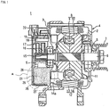
- FIG. 1 is a sectional view of a rotary electric machine to which a protective cover 25 according to a first embodiment of the present invention is mounted.
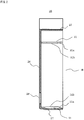
- FIG. 2 is a schematic sectional view of the protective cover 25, and
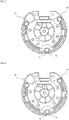
- FIG. 3 is a view of the protective cover 25 as seen from an opening portion B side.
- FIG. 4 is an enlarged view of a portion A of FIG. 1
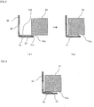
- FIGS. 5 are views for illustrating a state of mounting the protective cover 25 to the rotary electric machine.
- a vehicle AC power generator 1 is used as an example of the rotary electric machine.
- the vehicle AC power generator 1 includes a casing 4 formed of a front bracket 2 and a rear bracket 3, which are made of aluminum.
- a shaft 6 is supported in the casing 4 through intermediation of a pair of bearings 5 so as to be freely rotatable.
- One end side of the shaft 6 extends outward from the casing 4 on a front side, and a pulley 7 is firmly fixed thereto.
- a rotator 8 and a fan 11 are fixed to an intermediate portion of the shaft 6.
- a stator 12 is fixed inside the casing 4, so as to surround the rotator 8.
- Another end side of the shaft 6 extends outward from the casing 4 on a rear side, and a pair of slip rings 15, which is configured to supply a current to the rotator 8, is fixed thereto.
- a pair of brushes 16, a brush holder 17, a heat sink 18, a voltage regulator 19, a connector 20, and a rectifying device 21 are arranged outside the casing 4 on the rear side.
- the pair of brushes 16 are configured to slide against surfaces of the slip rings 15, respectively.
- the brush holder 17 is configured to accommodate the brushes 16 therein.
- the protective cover 25 is mounted to the rear bracket 3 of the casing 4 so as to cover, for example, the brush holder 17, the voltage regulator 19, and the rectifying device 21.
- the rotator 8 is a Lundell-type rotator, and includes a field winding 9 and a pole core 10.
- the field winding 9 is configured to generate magnetic flux when an excitation current is caused to flow therethrough.
- the pole core 10 is provided so as to cover the field winding 9, and has magnetic poles formed by the magnetic flux.
- the stator 12 includes a core 13 and a stator winding 14.
- the core 13 has a cylindrical shape.
- the stator winding 14 is wound around the core 13, and generates an alternating current based on a change in magnetic flux generated from the field winding 9 along with rotation of the rotator 8.
- the stator 12 is disposed so as to surround the rotator 8.
- the core 13 of the stator 12 is supported from both axial sides by the front bracket 2 and the rear bracket 3.
- a field current is supplied from a battery (not shown) through the brushes 16 and the slip rings 15 to the field winding 9 to generate the magnetic flux.
- N-poles and S-poles are formed on an outer periphery of the pole core 10 in an alternating manner in a circumferential direction of the pole core 10.
- a rotational torque of an engine is transmitted to the pulley 7 through a belt (not shown) to rotate the shaft 6 and the rotator 8. Then, a rotating magnetic field is applied to the stator winding 14 of the stator 12 to generate an electromotive force in the stator winding 14. Further, the AC electromotive force generated in the stator winding 14 is rectified into a direct current by the rectifying device 21. At the same time, a magnitude of an output voltage is regulated by the voltage regulator 19 and is then supplied to the battery and an in-vehicle electric load.
- the fan 11 is rotated in conjunction with the rotation of the rotator 8 to suck an outside air from intake holes formed in the protective cover 25. After cooling the heat sink 18 for the voltage regulator 19 and a heat sink for the rectifying device 21, the sucked outside air flows into the casing 4. Then, a direction of flow of the outside air reaching the vicinity of the fan 11 is changed to a circumferential direction of a rotation axis of the vehicle AC power generator 1 by the fan 11. After cooling a portion of the stator winding 14, which extends from the core 13, the outside air is discharged to the outside of the casing 4.
- the protective cover 25 is made of an insulating resin such as polybutylene terephthalate (PBT) or Nylon 66. As illustrated in FIG. 2 , the protective cover 25 includes a bottom portion 26 and a side wall 27.
- the bottom portion 26 has an approximately circular shape.
- the side wall 27 has an approximately cylindrical shape, and extends from the bottom portion 26 along an outer periphery of the bottom portion 26.
- a plurality of inner peripheral-side intake holes 28 and a plurality of outer peripheral-side intake holes 29 are formed in the bottom portion 26 of the protective cover 25 as intake holes for a cooling fluid to be sucked into the casing 4 by the fan 11.
- the side wall 27 of the protective cover 25 has guide ribs 31, which are formed on an inner side thereof and are arranged at three positions apart from each other along the outer periphery of the bottom portion 26.
- the three guide ribs 31 are formed to extend from the bottom portion 26 toward the opening portion B.
- a chamfered portion 31a is formed at an end of each of the guide ribs 31, which is located on a side closer to the opening portion B.
- FIGS. 5 are sectional views for illustrating a state of mounting the protective cover 25 in the vicinity of the rectifying device 21 that is included in the vehicle AC power generator 1.
- a side surface of each of components such as the rectifying device 21 refers to a surface of each of the components along the rotation axis of the vehicle AC power generator 1.
- a top portion 31b of the guide rib 31 is brought into contact with the side surface 21a of the rectifying device 21.
- the protective cover 25 is moved in a mounting direction along the side surface 21a of the rectifying device 21 to be mounted to the vehicle AC power generator 1.
- the top portion 31b of each of the guide ribs 31 is similarly brought into contact with a side surface of another component.
- each of the guide ribs 31 from the side wall 27 is formed so as to have a height equal to or larger than a gap between the side surface of each of the components, with which the top portion 31b of each of the guide ribs 31 is held in contact, and the protective cover 25.
- each of the guide ribs 31 is set equal to or larger than the gap between the side surface of each of the components and the protective cover 25 in consideration of elastic deformation of the side surface 27 of the protective cover 25, which is caused when the protective cover 25 is mounted to the vehicle AC power generator 1.
- the protective cover 25 when the protective cover 25 is to be mounted to the vehicle AC power generator 1, the top portions 31b of the plurality of guide ribs 31 formed on the protective cover 25 are brought into contact with the side surfaces of the plurality of components included in the vehicle AC power generator 1, respectively. In this manner, the protective cover 25 can be mounted while being positioned in a radial direction of the vehicle AC power generator 1 with the rotation axis as a center.
- the protective cover 25 With the protective cover 25 according to the first embodiment, misalignment of the protective cover 25 in the radial direction of the rotation axis with respect to the casing 4, which is caused by vibration generated at the time of mounting of the vehicle AC power generator 1 in a vehicle, can be prevented. Further, the guide ribs 31 of the protective cover 25 are formed on the protective cover 25 with use of the gaps between the side surfaces of the components and the protective cover 25. Thus, arrangement and structures of the components are not required to be limited. Specifically, the protective cover 25 can be formed without changing a shape and arrangement of the rectifying device 21.
- each of the chamfered portions 31a is formed linearly in the first embodiment, a shape of the chamfered portion 31a is not limited thereto.
- the chamfered portion 31a may be formed into a curved shape.
- each of the guide ribs 31 has a length from the bottom portion 26 to the vicinity of the opening portion B in a direction of the rotation axis, the length may be about half as in a case of a guide rib 32 illustrated in FIG. 6 .
- the side wall 27 is more likely to be elastically deformed, and thus workability is improved.
- the plurality of guide ribs 31 formed on the protective cover 25 may have different lengths. Specifically, the guide rib 31 illustrated in FIG. 4 and the guide rib 32 illustrated in FIG. 6 , which has a length smaller than that of the guide rib 31 of FIG. 4 , may be formed together on the single protective cover 25. In this case, the protective cover 25 is roughly positioned with respect to the vehicle AC power generator 1 with use of the guide rib 31 having a large length. Next, the positioning in the radial direction of the rotation axis of the vehicle AC power generator 1 is performed with use of the guide rib 32 having a small length. As a result, ease of positioning at the time of mounting of the protective cover 25 can be improved.
- the guide ribs 31 are arranged at the three positions in the first embodiment, the arrangement thereof is not limited thereto.
- the guide ribs 31 may be arranged at four positions as illustrated in FIG. 7 , or may be arranged at two positions so as to be opposed to each other as illustrated in FIG. 8 .
- one of the guide ribs 31 is brought into contact with the side surface 21a of the rectifying device 21 in the first embodiment, the contact of the guide ribs 31 is not limited thereto.
- the guide rib 31 may be brought into contact with a side surface of the voltage regulator 19, or may be brought into contact with a side surface of another component.
- the rotary electric machine has been described as the vehicle AC power generator 1 in the first embodiment, the rotary electric machine is not limited thereto.
- the rotary electric machine may be, for example, a vehicle electric motor or a vehicle generator motor.
Landscapes
- Engineering & Computer Science (AREA)
- Power Engineering (AREA)
- Physics & Mathematics (AREA)
- Thermal Sciences (AREA)
- Motor Or Generator Frames (AREA)
Abstract
Description
- The present invention relates to a mounting structure for mounting a cover, which is configured to protect a component of a rotary electric machine, to the rotary electric machine.
- In
Patent Literature 1, there is disclosed a vehicle AC power generator including a rotator, a stator, a rectifier, a voltage regulator, and a cylindrical protective cover. The rotator is disposed in a casing. The stator is supported by the casing. The rectifier and the voltage regulator are disposed outside the casing. The cylindrical protective cover includes a bottom portion and a peripheral wall portion, and is mounted to the casing so as to cover the rectifier and the voltage regulator. A protruding portion is formed on an inner surface of the protective cover. The protruding portion is to be fitted into a recessed portion formed on the rectifier and the voltage regulator. - [PTL 1]
JP 5395192 B2 - In recent years, along with expansion of a cabin space of a vehicle, downsizing of an engine room is demanded. Downsizing is also demanded for the vehicle AC power generator. There is also a demand of downsizing for a device such as the rectifier or the voltage regulator, which is mounted to the vehicle AC power generator . However, in the vehicle AC power generator disclosed in
Patent Literature 1, the recessed portion, which is to be fitted over the protruding portion formed on the inner surface of the protective cover, is required to be formed on the rectifier and the voltage regulator. The recessed portion causes limitation on arrangement of, for example, electronic components included in the rectifier and the voltage regulator, and such limitation on arrangement hinders downsizing. - Further, in the vehicle AC power generator disclosed in
Patent Literature 1, the protruding portion formed on the inner surface of the protective cover cannot be formed to have a height equal to or larger than a depth of the recessed portion formed on the rectifier or the voltage regulator. Thus, when the protective cover is to be mounted, it is not easy to position the protruding portion with respect to the recessed portion. Therefore, when the protruding portion and the recessed portion are misaligned, there arises a problem in that the protruding portion of the protective cover may interfere with the electronic component included in the rectifier or the voltage regulator to damage the electronic component. - The present invention has been made to solve the problems described above, and has an object to provide a protective cover, which is capable of eliminating need to form a shape that allows fitting to the protective cover on a rectifier or a voltage regulator and is capable of being easily mounted to a rotary electric machine such as a vehicle AC power generator without misalignment.
- According to one embodiment of the present invention, there is provided a protective cover for a rotary electric machine, including: a bottom portion formed into an approximately circular shape; a side wall, which extends from the bottom portion along an outer periphery of the bottom portion; and an opening portion, which has an approximately circular shape and is formed by an end of the side wall, which is located on a side opposite to the bottom portion, wherein the side wall has a plurality of guide ribs, which are formed on an inner side thereof and are arranged apart from each other along the outer periphery of the bottom portion, wherein each of the plurality of guide ribs extends from the bottom portion toward the opening portion and has a chamfered portion at an end on a side closer to the opening portion, and wherein each of the plurality of guide ribs is formed so that a height of a top portion of each of the plurality of guide ribs from the side wall allows the top portion to be brought into contact with a side surface of the component when the protective cover is mounted to the rotary electric machine.
- With the protective cover according to one embodiment of the present invention, when the protective cover, which is configured to cover the component of the rotary electric machine, is mounted to the rotary electric machine, the plurality of guide ribs formed on the inner side of the side wall of the protective cover are each brought into contact with the side surface of the component to position the protective cover in a radial direction of a rotation axis of the rotary electric machine. As a result, there is provided the protective cover, which is capable of eliminating the need to form the shape that allows the fitting to the protective cover on the component of the rotary electric machine, such as a rectifier or a voltage regulator, and is capable of being easily mounted to the rotary electric machine without misalignment.
-
-
FIG. 1 is a sectional view of a rotary electric machine to which a protective cover according to a first embodiment of the present invention is mounted as seen from a lateral side. -
FIG. 2 is a schematic sectional view of the protective cover. -
FIG. 3 is a view of the protective cover as seen from an opening portion side. -
FIG. 4 is an enlarged view of a portion A ofFIG. 1 . -
FIGS. 5 are views for illustrating a state of mounting the protective cover to the rotary electric machine. -
FIG. 6 is a view for illustrating a modification example of the protective cover according to the first embodiment. -
FIG. 7 is a view for illustrating another modification example of the protective cover according to the first embodiment. -
FIG. 8 is a view for illustrating still another modification example of the protective cover according to the first embodiment. - Now, a protective cover for a rotary electric machine according to an exemplary embodiment of the present invention is described referring to the accompanying drawings.
-
FIG. 1 is a sectional view of a rotary electric machine to which aprotective cover 25 according to a first embodiment of the present invention is mounted.FIG. 2 is a schematic sectional view of theprotective cover 25, andFIG. 3 is a view of theprotective cover 25 as seen from an opening portion B side.FIG. 4 is an enlarged view of a portion A ofFIG. 1 , andFIGS. 5 are views for illustrating a state of mounting theprotective cover 25 to the rotary electric machine. In the first embodiment, a vehicleAC power generator 1 is used as an example of the rotary electric machine. - As illustrated in
FIG. 1 , the vehicleAC power generator 1 includes a casing 4 formed of a front bracket 2 and a rear bracket 3, which are made of aluminum. Ashaft 6 is supported in the casing 4 through intermediation of a pair ofbearings 5 so as to be freely rotatable. - One end side of the
shaft 6 extends outward from the casing 4 on a front side, and apulley 7 is firmly fixed thereto. Arotator 8 and afan 11 are fixed to an intermediate portion of theshaft 6. Inside the casing 4, astator 12 is fixed so as to surround therotator 8. - Another end side of the
shaft 6 extends outward from the casing 4 on a rear side, and a pair ofslip rings 15, which is configured to supply a current to therotator 8, is fixed thereto. A pair ofbrushes 16, abrush holder 17, aheat sink 18, avoltage regulator 19, aconnector 20, and a rectifyingdevice 21 are arranged outside the casing 4 on the rear side. The pair ofbrushes 16 are configured to slide against surfaces of theslip rings 15, respectively. Thebrush holder 17 is configured to accommodate thebrushes 16 therein. - The
protective cover 25 is mounted to the rear bracket 3 of the casing 4 so as to cover, for example, thebrush holder 17, thevoltage regulator 19, and the rectifyingdevice 21. - The
rotator 8 is a Lundell-type rotator, and includes a field winding 9 and apole core 10. The field winding 9 is configured to generate magnetic flux when an excitation current is caused to flow therethrough. Thepole core 10 is provided so as to cover the field winding 9, and has magnetic poles formed by the magnetic flux. Thestator 12 includes a core 13 and a stator winding 14. The core 13 has a cylindrical shape. The stator winding 14 is wound around the core 13, and generates an alternating current based on a change in magnetic flux generated from the field winding 9 along with rotation of therotator 8. Thestator 12 is disposed so as to surround therotator 8. The core 13 of thestator 12 is supported from both axial sides by the front bracket 2 and the rear bracket 3. - In the vehicle
AC power generator 1 having the configuration described above, a field current is supplied from a battery (not shown) through thebrushes 16 and theslip rings 15 to the field winding 9 to generate the magnetic flux. By the magnetic flux, N-poles and S-poles are formed on an outer periphery of thepole core 10 in an alternating manner in a circumferential direction of thepole core 10. - Meanwhile, a rotational torque of an engine is transmitted to the
pulley 7 through a belt (not shown) to rotate theshaft 6 and therotator 8. Then, a rotating magnetic field is applied to the stator winding 14 of thestator 12 to generate an electromotive force in the stator winding 14. Further, the AC electromotive force generated in the stator winding 14 is rectified into a direct current by the rectifyingdevice 21. At the same time, a magnitude of an output voltage is regulated by thevoltage regulator 19 and is then supplied to the battery and an in-vehicle electric load. - The
fan 11 is rotated in conjunction with the rotation of therotator 8 to suck an outside air from intake holes formed in theprotective cover 25. After cooling theheat sink 18 for thevoltage regulator 19 and a heat sink for the rectifyingdevice 21, the sucked outside air flows into the casing 4. Then, a direction of flow of the outside air reaching the vicinity of thefan 11 is changed to a circumferential direction of a rotation axis of the vehicleAC power generator 1 by thefan 11. After cooling a portion of the stator winding 14, which extends from the core 13, the outside air is discharged to the outside of the casing 4. - Next, the
protective cover 25 and mounting of theprotective cover 25 are described with reference toFIG. 2 to FIGS. 5 . - The
protective cover 25 is made of an insulating resin such as polybutylene terephthalate (PBT) or Nylon 66. As illustrated inFIG. 2 , theprotective cover 25 includes abottom portion 26 and aside wall 27. Thebottom portion 26 has an approximately circular shape. Theside wall 27 has an approximately cylindrical shape, and extends from thebottom portion 26 along an outer periphery of thebottom portion 26. An end of theside wall 27, which is located on a side opposite to thebottom portion 26, forms the opening portion B having an approximately circular shape so that theprotective cover 25 is formed into a cylindrical shape having a closed end. - Further, as illustrated in
FIG. 3 , a plurality of inner peripheral-side intake holes 28 and a plurality of outer peripheral-side intake holes 29 are formed in thebottom portion 26 of theprotective cover 25 as intake holes for a cooling fluid to be sucked into the casing 4 by thefan 11. - As illustrated in
FIG. 2 to FIG. 4 , theside wall 27 of theprotective cover 25 hasguide ribs 31, which are formed on an inner side thereof and are arranged at three positions apart from each other along the outer periphery of thebottom portion 26. The threeguide ribs 31 are formed to extend from thebottom portion 26 toward the opening portion B. At an end of each of theguide ribs 31, which is located on a side closer to the opening portion B, a chamferedportion 31a is formed. - Next, a state of mounting the
protective cover 25 to the vehicleAC power generator 1 is described with reference toFIGS. 5. FIGS. 5 are sectional views for illustrating a state of mounting theprotective cover 25 in the vicinity of the rectifyingdevice 21 that is included in the vehicleAC power generator 1. - When the
protective cover 25 is to be mounted, as illustrated inFIG. 5A , the chamferedportion 31a formed at a distal end of theguide rib 31 is first brought into contact with aside surface 21a of the rectifyingdevice 21. As a result, theprotective cover 25 is guided to an appropriate mounting position. In the present invention, a side surface of each of components such as the rectifyingdevice 21 refers to a surface of each of the components along the rotation axis of the vehicleAC power generator 1. - Next, as illustrated in
FIG. 5B , atop portion 31b of theguide rib 31 is brought into contact with theside surface 21a of the rectifyingdevice 21. Theprotective cover 25 is moved in a mounting direction along theside surface 21a of the rectifyingdevice 21 to be mounted to the vehicleAC power generator 1. For the other twoguide ribs 31, thetop portion 31b of each of theguide ribs 31 is similarly brought into contact with a side surface of another component. - Then, when the
protective cover 25 is mounted to the vehicleAC power generator 1, thetop portion 31b of each of theguide ribs 31 is in a state of being held in contact with the side surface of any one of the components included in the vehicleAC power generator 1. Therefore, each of theguide ribs 31 from theside wall 27 is formed so as to have a height equal to or larger than a gap between the side surface of each of the components, with which thetop portion 31b of each of theguide ribs 31 is held in contact, and theprotective cover 25. The height of each of theguide ribs 31 is set equal to or larger than the gap between the side surface of each of the components and theprotective cover 25 in consideration of elastic deformation of theside surface 27 of theprotective cover 25, which is caused when theprotective cover 25 is mounted to the vehicleAC power generator 1. - As described above, with the
protective cover 25 according to the first embodiment, when theprotective cover 25 is to be mounted to the vehicleAC power generator 1, thetop portions 31b of the plurality ofguide ribs 31 formed on theprotective cover 25 are brought into contact with the side surfaces of the plurality of components included in the vehicleAC power generator 1, respectively. In this manner, theprotective cover 25 can be mounted while being positioned in a radial direction of the vehicleAC power generator 1 with the rotation axis as a center. - With the
protective cover 25 according to the first embodiment, misalignment of theprotective cover 25 in the radial direction of the rotation axis with respect to the casing 4, which is caused by vibration generated at the time of mounting of the vehicleAC power generator 1 in a vehicle, can be prevented. Further, theguide ribs 31 of theprotective cover 25 are formed on theprotective cover 25 with use of the gaps between the side surfaces of the components and theprotective cover 25. Thus, arrangement and structures of the components are not required to be limited. Specifically, theprotective cover 25 can be formed without changing a shape and arrangement of the rectifyingdevice 21. - Although each of the chamfered
portions 31a is formed linearly in the first embodiment, a shape of the chamferedportion 31a is not limited thereto. For example, the chamferedportion 31a may be formed into a curved shape. - Although each of the
guide ribs 31 has a length from thebottom portion 26 to the vicinity of the opening portion B in a direction of the rotation axis, the length may be about half as in a case of aguide rib 32 illustrated inFIG. 6 . In this case, theside wall 27 is more likely to be elastically deformed, and thus workability is improved. - The plurality of
guide ribs 31 formed on theprotective cover 25 may have different lengths. Specifically, theguide rib 31 illustrated inFIG. 4 and theguide rib 32 illustrated inFIG. 6 , which has a length smaller than that of theguide rib 31 ofFIG. 4 , may be formed together on the singleprotective cover 25. In this case, theprotective cover 25 is roughly positioned with respect to the vehicleAC power generator 1 with use of theguide rib 31 having a large length. Next, the positioning in the radial direction of the rotation axis of the vehicleAC power generator 1 is performed with use of theguide rib 32 having a small length. As a result, ease of positioning at the time of mounting of theprotective cover 25 can be improved. - Although the
guide ribs 31 are arranged at the three positions in the first embodiment, the arrangement thereof is not limited thereto. For example, theguide ribs 31 may be arranged at four positions as illustrated inFIG. 7 , or may be arranged at two positions so as to be opposed to each other as illustrated inFIG. 8 . Although one of theguide ribs 31 is brought into contact with theside surface 21a of the rectifyingdevice 21 in the first embodiment, the contact of theguide ribs 31 is not limited thereto. For example, theguide rib 31 may be brought into contact with a side surface of thevoltage regulator 19, or may be brought into contact with a side surface of another component. - Further, although the rotary electric machine has been described as the vehicle
AC power generator 1 in the first embodiment, the rotary electric machine is not limited thereto. The rotary electric machine may be, for example, a vehicle electric motor or a vehicle generator motor. - 1 vehicle AC power generator, 2 front bracket, 3 rear bracket, 4 casing, 6 shaft, 19 voltage regulator, 21 rectifying device, 21a side surface, 25 protective cover, 26 bottom portion, 27 side wall, 31, 32 guide rib, 31a chamfered portion, 31b top portion, B opening portion
Claims (4)
- A protective cover for a rotary electric machine, which is configured to protect a component of the rotary electric machine, comprising:a bottom portion formed into an approximately circular shape;a side wall, which extends from the bottom portion along an outer periphery of the bottom portion; andan opening portion, which has an approximately circular shape and is formed by an end of the side wall, which is located on a side opposite to the bottom portion,wherein the side wall has a plurality of guide ribs, which are formed on an inner side thereof and are arranged apart from each other along the outer periphery of the bottom portion,wherein each of the plurality of guide ribs extends from the bottom portion toward the opening portion and has a chamfered portion at an end on a side closer to the opening portion, andwherein each of the plurality of guide ribs is formed so that a height of a top portion of each of the plurality of guide ribs from the side wall allows the top portion to be brought into contact with a side surface of the component when the protective cover is mounted to the rotary electric machine.
- The protective cover for a rotary electric machine according to claim 1, wherein a length of at least one of the plurality of guide ribs from the bottom portion to the end, which is located on the side closer to the opening portion, is different from a length of another one of the guide ribs from the bottom portion to the end, which is located on the side closer to the opening portion.
- The protective cover for a rotary electric machine according to claim 1 or 2,
wherein the component comprises a rectifying device, and
wherein at least one of the plurality of guide ribs is brought into contact with a side surface of the rectifying device when the protective cover is mounted to the rotary electric machine. - The protective cover for a rotary electric machine according to any one of claims 1 to 3,
wherein the component comprises a voltage regulator, and
wherein at least one of the plurality of guide ribs is brought into contact with a side surface of the voltage regulator when the protective cover is mounted to the rotary electric machine.
Applications Claiming Priority (1)
| Application Number | Priority Date | Filing Date | Title |
|---|---|---|---|
| PCT/JP2016/083945 WO2018092208A1 (en) | 2016-11-16 | 2016-11-16 | Protective cover for dynamo-electric machine |
Publications (3)
| Publication Number | Publication Date |
|---|---|
| EP3544155A1 true EP3544155A1 (en) | 2019-09-25 |
| EP3544155A4 EP3544155A4 (en) | 2019-11-27 |
| EP3544155B1 EP3544155B1 (en) | 2021-10-06 |
Family
ID=62145301
Family Applications (1)
| Application Number | Title | Priority Date | Filing Date |
|---|---|---|---|
| EP16922009.2A Active EP3544155B1 (en) | 2016-11-16 | 2016-11-16 | Protective cover for dynamo-electric machine |
Country Status (6)
| Country | Link |
|---|---|
| US (1) | US11025128B2 (en) |
| EP (1) | EP3544155B1 (en) |
| JP (1) | JP6752897B2 (en) |
| CN (1) | CN109923763B (en) |
| MX (1) | MX2019005434A (en) |
| WO (1) | WO2018092208A1 (en) |
Family Cites Families (15)
| Publication number | Priority date | Publication date | Assignee | Title |
|---|---|---|---|---|
| JPS6051756U (en) * | 1983-09-16 | 1985-04-11 | 株式会社日立製作所 | Motor external impact protection cover |
| US4713568A (en) * | 1985-09-26 | 1987-12-15 | Siemens Aktiengesellschaft | Closed motor/transmission unit |
| US5959385A (en) * | 1995-10-19 | 1999-09-28 | Denso Corporation | Rotary machine having starter for vehicle |
| JPH11299140A (en) * | 1998-04-14 | 1999-10-29 | Nippon Densan Corp | Structure for attaching stator of motor |
| DE10361860A1 (en) * | 2003-12-30 | 2005-07-28 | Robert Bosch Gmbh | Protective cap, in particular for an alternator |
| JP4797779B2 (en) * | 2006-04-27 | 2011-10-19 | 株式会社デンソー | AC generator for vehicles |
| JP5354888B2 (en) * | 2007-11-05 | 2013-11-27 | 株式会社ミツバ | Brushless motor |
| DE102009010782A1 (en) * | 2009-02-26 | 2010-09-09 | Bühler Motor GmbH | Stator for an electronically commutated DC motor |
| CN102668337B (en) | 2009-11-24 | 2015-05-20 | 三菱电机株式会社 | AC generator for vehicle |
| CN103004059B (en) * | 2010-07-14 | 2016-05-18 | 松下知识产权经营株式会社 | Brushless electric machine and manufacture method thereof |
| US9246367B2 (en) * | 2011-11-11 | 2016-01-26 | Mitsubishi Electric Corporation | Automotive rotary electric machine |
| JP5752320B2 (en) * | 2012-04-18 | 2015-07-22 | 三菱電機株式会社 | AC generator |
| JP5832507B2 (en) * | 2013-11-21 | 2015-12-16 | 三菱電機株式会社 | AC generator |
| JP6072167B2 (en) * | 2015-08-18 | 2017-02-01 | 三菱電機株式会社 | AC generator |
| CN106026479B (en) * | 2016-07-29 | 2018-10-23 | 苏州工业园区星德胜电机有限公司 | Motor casing and low vibration motor including the shell |
-
2016
- 2016-11-16 EP EP16922009.2A patent/EP3544155B1/en active Active
- 2016-11-16 US US16/345,003 patent/US11025128B2/en active Active
- 2016-11-16 MX MX2019005434A patent/MX2019005434A/en unknown
- 2016-11-16 JP JP2018550913A patent/JP6752897B2/en not_active Expired - Fee Related
- 2016-11-16 CN CN201680090690.1A patent/CN109923763B/en active Active
- 2016-11-16 WO PCT/JP2016/083945 patent/WO2018092208A1/en unknown
Also Published As
| Publication number | Publication date |
|---|---|
| EP3544155A4 (en) | 2019-11-27 |
| CN109923763B (en) | 2022-05-13 |
| JP6752897B2 (en) | 2020-09-09 |
| US20190273411A1 (en) | 2019-09-05 |
| CN109923763A (en) | 2019-06-21 |
| EP3544155B1 (en) | 2021-10-06 |
| US11025128B2 (en) | 2021-06-01 |
| WO2018092208A1 (en) | 2018-05-24 |
| JPWO2018092208A1 (en) | 2019-03-07 |
| MX2019005434A (en) | 2019-07-10 |
Similar Documents
| Publication | Publication Date | Title |
|---|---|---|
| EP3297143B1 (en) | Vehicle ac power generator | |
| US8937416B2 (en) | Automotive dynamoelectric machine with a protective cover for voltage regulator and rectifier elements | |
| EP2966760A1 (en) | Rotating electrical machine | |
| US9614407B2 (en) | Rotary electric machine stator | |
| EP2779368A1 (en) | Rotating electrical machine for vehicle | |
| EP3018800A1 (en) | Rotating electric machine | |
| JP5631511B2 (en) | Rotating electric machine | |
| EP2840685B1 (en) | Ac generator | |
| EP2787608B1 (en) | Rotating electrical machine for vehicle | |
| EP3065269B1 (en) | Vehicle rotating electric machine | |
| EP3291419B1 (en) | Rotating electric machine | |
| JP6351857B2 (en) | Rotating electric machine for vehicles | |
| JP6234603B2 (en) | Rotating electric machine for vehicles | |
| US11025128B2 (en) | Protective cover for rotary electric machine | |
| JP2007195355A (en) | Alternator for brushless vehicle | |
| JP2014112983A (en) | Rotary electric machine | |
| CN109842258B (en) | Brushless motor and blower |
Legal Events
| Date | Code | Title | Description |
|---|---|---|---|
| STAA | Information on the status of an ep patent application or granted ep patent |
Free format text: STATUS: THE INTERNATIONAL PUBLICATION HAS BEEN MADE |
|
| PUAI | Public reference made under article 153(3) epc to a published international application that has entered the european phase |
Free format text: ORIGINAL CODE: 0009012 |
|
| STAA | Information on the status of an ep patent application or granted ep patent |
Free format text: STATUS: REQUEST FOR EXAMINATION WAS MADE |
|
| 17P | Request for examination filed |
Effective date: 20190425 |
|
| AK | Designated contracting states |
Kind code of ref document: A1 Designated state(s): AL AT BE BG CH CY CZ DE DK EE ES FI FR GB GR HR HU IE IS IT LI LT LU LV MC MK MT NL NO PL PT RO RS SE SI SK SM TR |
|
| AX | Request for extension of the european patent |
Extension state: BA ME |
|
| A4 | Supplementary search report drawn up and despatched |
Effective date: 20191025 |
|
| RIC1 | Information provided on ipc code assigned before grant |
Ipc: H02K 5/08 20060101ALI20191021BHEP Ipc: H02K 11/04 20160101ALI20191021BHEP Ipc: H02K 5/04 20060101AFI20191021BHEP Ipc: H02K 7/18 20060101ALN20191021BHEP |
|
| DAV | Request for validation of the european patent (deleted) | ||
| DAX | Request for extension of the european patent (deleted) | ||
| STAA | Information on the status of an ep patent application or granted ep patent |
Free format text: STATUS: EXAMINATION IS IN PROGRESS |
|
| STAA | Information on the status of an ep patent application or granted ep patent |
Free format text: STATUS: EXAMINATION IS IN PROGRESS |
|
| 17Q | First examination report despatched |
Effective date: 20201110 |
|
| GRAP | Despatch of communication of intention to grant a patent |
Free format text: ORIGINAL CODE: EPIDOSNIGR1 |
|
| STAA | Information on the status of an ep patent application or granted ep patent |
Free format text: STATUS: GRANT OF PATENT IS INTENDED |
|
| RIC1 | Information provided on ipc code assigned before grant |
Ipc: H02K 5/04 20060101AFI20210531BHEP Ipc: H02K 5/08 20060101ALI20210531BHEP Ipc: H02K 11/04 20160101ALI20210531BHEP Ipc: H02K 7/18 20060101ALN20210531BHEP |
|
| INTG | Intention to grant announced |
Effective date: 20210625 |
|
| GRAS | Grant fee paid |
Free format text: ORIGINAL CODE: EPIDOSNIGR3 |
|
| GRAA | (expected) grant |
Free format text: ORIGINAL CODE: 0009210 |
|
| STAA | Information on the status of an ep patent application or granted ep patent |
Free format text: STATUS: THE PATENT HAS BEEN GRANTED |
|
| AK | Designated contracting states |
Kind code of ref document: B1 Designated state(s): AL AT BE BG CH CY CZ DE DK EE ES FI FR GB GR HR HU IE IS IT LI LT LU LV MC MK MT NL NO PL PT RO RS SE SI SK SM TR |
|
| REG | Reference to a national code |
Ref country code: GB Ref legal event code: FG4D |
|
| REG | Reference to a national code |
Ref country code: CH Ref legal event code: EP Ref country code: AT Ref legal event code: REF Ref document number: 1437044 Country of ref document: AT Kind code of ref document: T Effective date: 20211015 |
|
| REG | Reference to a national code |
Ref country code: IE Ref legal event code: FG4D |
|
| REG | Reference to a national code |
Ref country code: DE Ref legal event code: R096 Ref document number: 602016064782 Country of ref document: DE |
|
| REG | Reference to a national code |
Ref country code: LT Ref legal event code: MG9D |
|
| REG | Reference to a national code |
Ref country code: NL Ref legal event code: MP Effective date: 20211006 |
|
| REG | Reference to a national code |
Ref country code: AT Ref legal event code: MK05 Ref document number: 1437044 Country of ref document: AT Kind code of ref document: T Effective date: 20211006 |
|
| PG25 | Lapsed in a contracting state [announced via postgrant information from national office to epo] |
Ref country code: RS Free format text: LAPSE BECAUSE OF FAILURE TO SUBMIT A TRANSLATION OF THE DESCRIPTION OR TO PAY THE FEE WITHIN THE PRESCRIBED TIME-LIMIT Effective date: 20211006 Ref country code: LT Free format text: LAPSE BECAUSE OF FAILURE TO SUBMIT A TRANSLATION OF THE DESCRIPTION OR TO PAY THE FEE WITHIN THE PRESCRIBED TIME-LIMIT Effective date: 20211006 Ref country code: FI Free format text: LAPSE BECAUSE OF FAILURE TO SUBMIT A TRANSLATION OF THE DESCRIPTION OR TO PAY THE FEE WITHIN THE PRESCRIBED TIME-LIMIT Effective date: 20211006 Ref country code: BG Free format text: LAPSE BECAUSE OF FAILURE TO SUBMIT A TRANSLATION OF THE DESCRIPTION OR TO PAY THE FEE WITHIN THE PRESCRIBED TIME-LIMIT Effective date: 20220106 Ref country code: AT Free format text: LAPSE BECAUSE OF FAILURE TO SUBMIT A TRANSLATION OF THE DESCRIPTION OR TO PAY THE FEE WITHIN THE PRESCRIBED TIME-LIMIT Effective date: 20211006 |
|
| PG25 | Lapsed in a contracting state [announced via postgrant information from national office to epo] |
Ref country code: IS Free format text: LAPSE BECAUSE OF FAILURE TO SUBMIT A TRANSLATION OF THE DESCRIPTION OR TO PAY THE FEE WITHIN THE PRESCRIBED TIME-LIMIT Effective date: 20220206 Ref country code: SE Free format text: LAPSE BECAUSE OF FAILURE TO SUBMIT A TRANSLATION OF THE DESCRIPTION OR TO PAY THE FEE WITHIN THE PRESCRIBED TIME-LIMIT Effective date: 20211006 Ref country code: PT Free format text: LAPSE BECAUSE OF FAILURE TO SUBMIT A TRANSLATION OF THE DESCRIPTION OR TO PAY THE FEE WITHIN THE PRESCRIBED TIME-LIMIT Effective date: 20220207 Ref country code: PL Free format text: LAPSE BECAUSE OF FAILURE TO SUBMIT A TRANSLATION OF THE DESCRIPTION OR TO PAY THE FEE WITHIN THE PRESCRIBED TIME-LIMIT Effective date: 20211006 Ref country code: NO Free format text: LAPSE BECAUSE OF FAILURE TO SUBMIT A TRANSLATION OF THE DESCRIPTION OR TO PAY THE FEE WITHIN THE PRESCRIBED TIME-LIMIT Effective date: 20220106 Ref country code: NL Free format text: LAPSE BECAUSE OF FAILURE TO SUBMIT A TRANSLATION OF THE DESCRIPTION OR TO PAY THE FEE WITHIN THE PRESCRIBED TIME-LIMIT Effective date: 20211006 Ref country code: LV Free format text: LAPSE BECAUSE OF FAILURE TO SUBMIT A TRANSLATION OF THE DESCRIPTION OR TO PAY THE FEE WITHIN THE PRESCRIBED TIME-LIMIT Effective date: 20211006 Ref country code: HR Free format text: LAPSE BECAUSE OF FAILURE TO SUBMIT A TRANSLATION OF THE DESCRIPTION OR TO PAY THE FEE WITHIN THE PRESCRIBED TIME-LIMIT Effective date: 20211006 Ref country code: GR Free format text: LAPSE BECAUSE OF FAILURE TO SUBMIT A TRANSLATION OF THE DESCRIPTION OR TO PAY THE FEE WITHIN THE PRESCRIBED TIME-LIMIT Effective date: 20220107 Ref country code: ES Free format text: LAPSE BECAUSE OF FAILURE TO SUBMIT A TRANSLATION OF THE DESCRIPTION OR TO PAY THE FEE WITHIN THE PRESCRIBED TIME-LIMIT Effective date: 20211006 |
|
| REG | Reference to a national code |
Ref country code: CH Ref legal event code: PL |
|
| REG | Reference to a national code |
Ref country code: DE Ref legal event code: R097 Ref document number: 602016064782 Country of ref document: DE |
|
| PG25 | Lapsed in a contracting state [announced via postgrant information from national office to epo] |
Ref country code: SM Free format text: LAPSE BECAUSE OF FAILURE TO SUBMIT A TRANSLATION OF THE DESCRIPTION OR TO PAY THE FEE WITHIN THE PRESCRIBED TIME-LIMIT Effective date: 20211006 Ref country code: SK Free format text: LAPSE BECAUSE OF FAILURE TO SUBMIT A TRANSLATION OF THE DESCRIPTION OR TO PAY THE FEE WITHIN THE PRESCRIBED TIME-LIMIT Effective date: 20211006 Ref country code: RO Free format text: LAPSE BECAUSE OF FAILURE TO SUBMIT A TRANSLATION OF THE DESCRIPTION OR TO PAY THE FEE WITHIN THE PRESCRIBED TIME-LIMIT Effective date: 20211006 Ref country code: MC Free format text: LAPSE BECAUSE OF FAILURE TO SUBMIT A TRANSLATION OF THE DESCRIPTION OR TO PAY THE FEE WITHIN THE PRESCRIBED TIME-LIMIT Effective date: 20211006 Ref country code: LU Free format text: LAPSE BECAUSE OF NON-PAYMENT OF DUE FEES Effective date: 20211116 Ref country code: EE Free format text: LAPSE BECAUSE OF FAILURE TO SUBMIT A TRANSLATION OF THE DESCRIPTION OR TO PAY THE FEE WITHIN THE PRESCRIBED TIME-LIMIT Effective date: 20211006 Ref country code: DK Free format text: LAPSE BECAUSE OF FAILURE TO SUBMIT A TRANSLATION OF THE DESCRIPTION OR TO PAY THE FEE WITHIN THE PRESCRIBED TIME-LIMIT Effective date: 20211006 Ref country code: CZ Free format text: LAPSE BECAUSE OF FAILURE TO SUBMIT A TRANSLATION OF THE DESCRIPTION OR TO PAY THE FEE WITHIN THE PRESCRIBED TIME-LIMIT Effective date: 20211006 Ref country code: BE Free format text: LAPSE BECAUSE OF NON-PAYMENT OF DUE FEES Effective date: 20211130 |
|
| REG | Reference to a national code |
Ref country code: BE Ref legal event code: MM Effective date: 20211130 |
|
| PLBE | No opposition filed within time limit |
Free format text: ORIGINAL CODE: 0009261 |
|
| STAA | Information on the status of an ep patent application or granted ep patent |
Free format text: STATUS: NO OPPOSITION FILED WITHIN TIME LIMIT |
|
| PG25 | Lapsed in a contracting state [announced via postgrant information from national office to epo] |
Ref country code: LI Free format text: LAPSE BECAUSE OF NON-PAYMENT OF DUE FEES Effective date: 20211130 Ref country code: CH Free format text: LAPSE BECAUSE OF NON-PAYMENT OF DUE FEES Effective date: 20211130 |
|
| 26N | No opposition filed |
Effective date: 20220707 |
|
| GBPC | Gb: european patent ceased through non-payment of renewal fee |
Effective date: 20220106 |
|
| PG25 | Lapsed in a contracting state [announced via postgrant information from national office to epo] |
Ref country code: IE Free format text: LAPSE BECAUSE OF NON-PAYMENT OF DUE FEES Effective date: 20211116 Ref country code: GB Free format text: LAPSE BECAUSE OF NON-PAYMENT OF DUE FEES Effective date: 20220106 Ref country code: AL Free format text: LAPSE BECAUSE OF FAILURE TO SUBMIT A TRANSLATION OF THE DESCRIPTION OR TO PAY THE FEE WITHIN THE PRESCRIBED TIME-LIMIT Effective date: 20211006 |
|
| PG25 | Lapsed in a contracting state [announced via postgrant information from national office to epo] |
Ref country code: SI Free format text: LAPSE BECAUSE OF FAILURE TO SUBMIT A TRANSLATION OF THE DESCRIPTION OR TO PAY THE FEE WITHIN THE PRESCRIBED TIME-LIMIT Effective date: 20211006 |
|
| PGFP | Annual fee paid to national office [announced via postgrant information from national office to epo] |
Ref country code: FR Payment date: 20221010 Year of fee payment: 7 |
|
| PGFP | Annual fee paid to national office [announced via postgrant information from national office to epo] |
Ref country code: DE Payment date: 20220621 Year of fee payment: 7 |
|
| PG25 | Lapsed in a contracting state [announced via postgrant information from national office to epo] |
Ref country code: IT Free format text: LAPSE BECAUSE OF FAILURE TO SUBMIT A TRANSLATION OF THE DESCRIPTION OR TO PAY THE FEE WITHIN THE PRESCRIBED TIME-LIMIT Effective date: 20211006 |
|
| P01 | Opt-out of the competence of the unified patent court (upc) registered |
Effective date: 20230512 |
|
| PG25 | Lapsed in a contracting state [announced via postgrant information from national office to epo] |
Ref country code: CY Free format text: LAPSE BECAUSE OF FAILURE TO SUBMIT A TRANSLATION OF THE DESCRIPTION OR TO PAY THE FEE WITHIN THE PRESCRIBED TIME-LIMIT Effective date: 20211006 |
|
| PG25 | Lapsed in a contracting state [announced via postgrant information from national office to epo] |
Ref country code: HU Free format text: LAPSE BECAUSE OF FAILURE TO SUBMIT A TRANSLATION OF THE DESCRIPTION OR TO PAY THE FEE WITHIN THE PRESCRIBED TIME-LIMIT; INVALID AB INITIO Effective date: 20161116 |
|
| PG25 | Lapsed in a contracting state [announced via postgrant information from national office to epo] |
Ref country code: MK Free format text: LAPSE BECAUSE OF FAILURE TO SUBMIT A TRANSLATION OF THE DESCRIPTION OR TO PAY THE FEE WITHIN THE PRESCRIBED TIME-LIMIT Effective date: 20211006 |
|
| REG | Reference to a national code |
Ref country code: DE Ref legal event code: R119 Ref document number: 602016064782 Country of ref document: DE |