EP3544132A1 - Axial fixierbare dichtungsanordnung für eine kabeldurchführung - Google Patents
Axial fixierbare dichtungsanordnung für eine kabeldurchführung Download PDFInfo
- Publication number
- EP3544132A1 EP3544132A1 EP18305326.3A EP18305326A EP3544132A1 EP 3544132 A1 EP3544132 A1 EP 3544132A1 EP 18305326 A EP18305326 A EP 18305326A EP 3544132 A1 EP3544132 A1 EP 3544132A1
- Authority
- EP
- European Patent Office
- Prior art keywords
- cable
- clamping
- seal assembly
- sealing
- housing
- Prior art date
- Legal status (The legal status is an assumption and is not a legal conclusion. Google has not performed a legal analysis and makes no representation as to the accuracy of the status listed.)
- Granted
Links
Images

Classifications
-
- H—ELECTRICITY
- H02—GENERATION; CONVERSION OR DISTRIBUTION OF ELECTRIC POWER
- H02G—INSTALLATION OF ELECTRIC CABLES OR LINES, OR OF COMBINED OPTICAL AND ELECTRIC CABLES OR LINES
- H02G3/00—Installations of electric cables or lines or protective tubing therefor in or on buildings, equivalent structures or vehicles
- H02G3/22—Installations of cables or lines through walls, floors or ceilings, e.g. into buildings
-
- H—ELECTRICITY
- H02—GENERATION; CONVERSION OR DISTRIBUTION OF ELECTRIC POWER
- H02G—INSTALLATION OF ELECTRIC CABLES OR LINES, OR OF COMBINED OPTICAL AND ELECTRIC CABLES OR LINES
- H02G3/00—Installations of electric cables or lines or protective tubing therefor in or on buildings, equivalent structures or vehicles
- H02G3/02—Details
- H02G3/06—Joints for connecting lengths of protective tubing or channels, to each other or to casings, e.g. to distribution boxes; Ensuring electrical continuity in the joint
- H02G3/0616—Joints for connecting tubing to casing
- H02G3/0625—Joints for connecting tubing to casing with means for preventing disengagement of conductors
- H02G3/065—Joints for connecting tubing to casing with means for preventing disengagement of conductors with means biting into the conductor-insulation, e.g. teeth-like elements or gripping fingers
-
- H—ELECTRICITY
- H02—GENERATION; CONVERSION OR DISTRIBUTION OF ELECTRIC POWER
- H02G—INSTALLATION OF ELECTRIC CABLES OR LINES, OR OF COMBINED OPTICAL AND ELECTRIC CABLES OR LINES
- H02G3/00—Installations of electric cables or lines or protective tubing therefor in or on buildings, equivalent structures or vehicles
- H02G3/02—Details
- H02G3/06—Joints for connecting lengths of protective tubing or channels, to each other or to casings, e.g. to distribution boxes; Ensuring electrical continuity in the joint
- H02G3/0616—Joints for connecting tubing to casing
- H02G3/0625—Joints for connecting tubing to casing with means for preventing disengagement of conductors
- H02G3/0658—Joints for connecting tubing to casing with means for preventing disengagement of conductors with means constricting the conductor-insulation
Definitions
- the invention relates to a sealing arrangement for a cable inserted into a housing.
- the electrical components and devices are often arranged in closed housings, e.g. B. to protect them from environmental influences such as dust, liquids or gases that could affect their function or life, or to protect against accidental contact.
- the electrical components and devices must be supplied with electrical energy via leads, and leads for sensors, control or data signals to the components and devices lead or lead away from them.
- These cables or cables must be routed through corresponding openings in the housing, which are also referred to as cable bushings.
- the grommets may be formed as holes or punches in a housing wall having a larger diameter than the outer diameter of a cable sheath to facilitate insertion of the cables, which may also be a plug or other terminal on the inserted into the housing End may have.
- the cable glands In order to restore the tightness of the housing, the cable glands must be closed again by means of appropriate sealing means.
- mechanical protection of the cable in the area of the cable bushing against scuffing or bending with impermissibly small bending radii may be desired.
- a fixation of the guided into the housing cable against displacement in the axial direction may be required.
- a known from the prior art sealing arrangement for a cable feedthrough has two parts which are pushed from both sides of a cable gland of a housing on the guided through the cable gland cable and then connected to each other releasably or permanently.
- the connection may comprise a screw or clamp connection and be additionally secured by gluing or the like against unintentional loosening.
- the sealing of the interior of the housing against the ingress of solids and fluids is usually carried out at two points.
- a first seal is provided between the cable sheath and the seal assembly, a second seal is provided between at least one of the two connected parts of the seal assembly and the housing wall. This results in two places where the seal can fail.
- Such a sealing arrangement is, for example, from the DE3604213A1 known.
- the DE3604213A1 shows a two-piece seal assembly in which a nut is screwed onto a feedthrough, whereby clamping tongues are pressed against the cable sheath and thereby fix the cable.
- the seal of the seal assembly against the housing is effected by the axially in the cable direction on both sides against the housing wall oppressive parts of the seal assembly.
- the two interconnected parts must have a diameter which is considerably larger than the hole of the cable gland.
- the length of the leadthrough part must be greater than the wall thickness of the housing, but must not be too large, otherwise the nut completely compresses the conical part, with which the clamping tongues are pressed against the cable sheath, without the axial sealing effect is achieved.
- it is necessary in this type of sealing arrangement that the installation site is accessible from both sides.
- the DE7729783U1 shows a similar construction, but with a lying in the clamping region soft sealing member which is pressed when screwing the two parts of the sealing device through the conical part of the nut against the cable sheath.
- the DE19848216A1 also shows a similar construction, wherein an annular soft part is arranged in the nut, which is pressed together with the sealing body by a conical part thereof against the cable sheath when screwed together.
- the FR1282648A shows a two-part seal assembly with a first seal member which is passed through a hole in a housing and locked there and a second seal member which is screwed into the first seal member, wherein a conical part cooperating with a corresponding inner cone of the first seal member and the first Sealing part presses radially outward in the region of the implementation.
- the cable is fixed by the conical part.
- the materials of the first and second sealing part must each have a certain minimum hardness in order to be screwed together.
- a certain elasticity is required so that a sufficient sealing effect is achieved.
- the locking in the cable gland requires a construction adapted to the wall thickness, so that a corresponding multiplicity of adapted sealing arrangements must be kept ready for different wall thicknesses and for different cable diameters.
- the US3548079 shows a two-part cable gland with a sealing body and a nut, wherein the nut presses a conical part of the same against the cable jacket when screwed to the sealing body.
- the seal against the housing wall is effected by a latching region of the sealing body and by the nut on this radially and axially acting force.
- a certain minimum hardness of the two parts is required so that they are screwed together.
- the provision of a corresponding plurality of adapted sealing arrangements is required.
- the present invention has the object to provide a cable seal assembly which overcomes or at least reduces one or more of the problems mentioned above.
- an axially fixable on a cable seal assembly for a cable feedthrough in a housing which comprises a clamping body and a slidable on the clamping body clamping ring.
- a sealing part is connected to the clamping body in such a way that, at least in the mounted state of the sealing arrangement, it is not detachable from the clamping body, or at least only with great expenditure of force.
- the connection may comprise a non-positive and / or positive connection of clamping body and sealing part, but also an alternative or additional cohesive connection is possible, for example.
- the sealing part is preferably made of an elastically deformable first material
- the clamping body is made of a second elastically deformable material.
- the second material may have a greater rigidity or lower elasticity and / or a greater hardness than the first material.
- the clamping body and sealing arrangement are a single part, which is made of a material having a suitable elasticity and / or hardness.
- the clamping ring is pushed axially over a part of the clamp body.
- the clamping ring can be fixed in the assembled state releasably or permanently, for example. By a positive connection with a corresponding structure of the clamp body or by an adhesive bond.
- the clamping body may have clamping tongues or clamping fingers along a circumference, which can be moved radially toward one another by the clamping ring.
- the clamping tongues or clamping fingers may also have structures facing the cable, which locally deform a jacket of a cable inserted into the sealing arrangement with a slipped clamping ring and thus produce a positive connection or at least generate local force peaks, which prevent or complicate an axial displacement of the seal arrangement.
- These structures include, for example, webs, teeth, nubs or grooves.
- the clamping ring in a mounted position with the clamping body is positively connected so that the clamping ring can be solved only by applying a predetermined minimum force.
- the clamping ring has an outer diameter which is larger than a cable feedthrough into a housing.
- An axially acting on the cable with the seal assembly force which acts against the Aufschiebecardi on the clamping ring causes an increasing Clamping action of the clamping fingers or clamping tongues.
- the clamping ring can be released from the mounting position and it can reduce the clamping action of the clamping fingers or clamping tongues occur, or the clamping action is released.
- This embodiment may be advantageous when an axial mechanical tensile load in one direction is expected.
- the clamping ring can lock against pulling the cable with the seal assembly through the cable gland.
- the clamping ring releases from the clamping tongues or clamping fingers and releases the cable.
- the cable can now be moved axially in the seal assembly. For example, with a sufficiently large axial movement of the cable, a connector may come loose from a socket, thereby reducing the risk of the cable tearing.
- the clamping ring can also be mounted so that an axial mechanical tensile load causes an increase in the clamping action.
- the sealing part inserted into a cable bushing of a housing is exposed in a plane radially against the cable and against the cable feedthrough forces.
- the radially acting forces are generated by the compression of at least those parts of the elastic sealing part, which have a larger diameter than the cable gland and are located within the cable gland.
- the elastic seal member thus causes a circumferential radial seal against the cable sheath and the cable gland. Unevenness of the surface of the grommet and / or the cable are compensated by the elastic sealing part.
- the sealing part may each have one or more circumferential grooves or webs on a surface facing the cable and / or a surface facing the cable bushing. These can be more easily deformed and can even better adjust to unevenness of the surface of the cable gland and / or the cable sheath as a sealing member having a smooth surface in the region of the sealing surfaces. If several circumferential grooves or webs are present, these form several successive seals. If the cable bushing along its inner circumference also has circumferential grooves or webs can be achieved by intermeshing grooves or webs of sealing part or cable bushing securing the seal assembly against axial displacement. In addition, the area available for the seal increases.
- the sealing member has an axial length which is greater than a wall thickness of a housing into which the sealing member is inserted. The outside of the wall with the cable bushing located areas of the sealing member are not compressed and cause an additional barrier against axial displacement of the assembled seal assembly.
- a respective sealing part is provided at axially opposite ends of the clamping body, and at least one clamping ring is displaceably mounted between the sealing parts.
- the sealing parts are at a distance from each other, which corresponds substantially to a wall thickness of the cable gland. When installed, this seals both sides of the grommet against the ingress of fluids or solids.
- the clamping body with the sealing part and the clamping ring are first pushed onto the cable and brought to a desired position.
- the pushing is done substantially without radially acting forces, so that the force required for the axial pushing force is small.
- One end of the cable can already be inserted through the cable gland into the housing.
- the clamping ring On the at the desired position on the cable positioned clamp body is pushed the clamping ring, whereby the seal assembly is fixed on the cable.
- the seal assembly with the cable is now inserted into the grommet and positioned so that the seal member comes to rest in the grommet.
- the sealing part is compressed.
- the sealing arrangement has a larger cross-section than the cable bushing, the sealing part presses in the radial direction circumferentially against the cable and the cable bushing, so that the cable bushing is sealed against the ingress of fluids and solids.
- the radially acting force causes a fixation of the seal assembly in the cable gland.
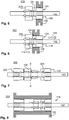
- FIG. 1 shows a schematic sectional view of a first inventive exemplary seal assembly 100 in a not fixed to a cable 102 position.
- the sealing arrangement comprises a clamping body 104, with which a sealing part 106 is connected.
- sealing member 106 and clamping body 104 are connected by means of a positive connection 105, highlighted by the dotted ellipse.
- Other types of connection such as gluing, welding, etc. or combinations of different types of connection are also conceivable.
- the seal assembly also includes a clamping ring 108. Clamping body 104 with sealing member 106 and clamping ring 108 are movable on the cable 102 in the axial direction and can be brought to a desired position on the cable 102.
- the clamping body 104 has clamping fingers or clamping tongues 110, which are flexible against the surface of the cable 102 movable.
- the clamping body 104 also has one or more recesses 112, which in the mounted state with one or more corresponding radially inwardly projecting parts 114 - highlighted by the dotted ellipse - of the clamping ring 108 form a positive connection.
- the recess 112 may be configured annularly circumferential or may be formed only in some areas of the clamping body 104. In the latter case, the inwardly projecting parts 114 of the clamping ring must be aligned prior to assembly accordingly.
- the clamping ring 108 may be made of a flexible material in order to be guided by the clamping fingers or clamping tongues 110 during assembly.
- the clamping ring 108 in the axial direction in the region of the projecting part 114 notches or slots (not shown in the figure), which allow greater mobility of the projecting parts 114 and thereby facilitate assembly.
- the sealing member 106 is provided on an outwardly facing outer surface 116 and on an inner surface 118 facing the cable 102 with radially encircling grooves 120. Outer and / or inner surfaces 116, 118 may also be implemented without the grooves 120.
- FIG. 2 shows a schematic sectional view of the first exemplary seal assembly 100 according to the invention in a fixed position on the cable 102 position.
- the clamping ring 108 is pushed over the clamping fingers or clamping tongues 110 and presses them against the surface of the cable 102.
- Projecting parts of the clamping fingers or clamping tongues 110 press on the jacket of the cable 102 and form with the resulting recesses in the cable sheath a positive connection.
- the projecting parts 114 of the clamping ring 108 are mounted in the recess or cavities 112 of the clamping body 104 and also form a positive connection (shown in the figure in the dotted ellipse).
- a section of a housing wall 126 is shown with a cable bushing 124 in which the seal assembly 100 is to be mounted.
- FIG. 3 shows a schematic sectional view of the fixed on the cable 102 first inventive exemplary seal assembly 100 FIG. 2 after mounting in a grommet 124 through a housing wall 126.
- the sealing part 106 has an axial length which substantially corresponds to the thickness of the housing wall 126.
- the sealing member 106 is radially compressed, which is indicated in the figure by the deformed grooves 120. It is readily apparent that in the sealing member 106 radially inwardly and outwardly forces act in a plane with the housing wall, thus ensuring the sealing of the cable gland.
- FIG. 4 shows a schematic sectional view of the fixed on the cable 102 first inventive exemplary seal assembly 100 FIG. 2 after mounting in a grommet 124 with a smaller wall thickness.
- the edge of the sealing part 106 has expanded again after being pushed through the cable lead-through 124.
- an additional safeguard against withdrawal of the sealing arrangement 100 is achieved. because first the force for the compression of the sealing part must be applied again. If the axial length of the sealing member 106 is even greater, 124 parts of the sealing member may remain largely uncompressed on both sides of the grommet and thus form a safeguard against displacement in both axial directions.
- the grommet 124 may have a chamfer (not shown in the figure) on one or both sides which facilitate insertion of the sealing member 106.
- FIG. 5 shows a schematic sectional view of a fixed to a cable 102 second inventive exemplary seal assembly 200 after installation in a cable gland 124.
- the clamping ring 108 has a larger diameter than the opening of the cable gland 124, while the clamping body 104 has a diameter which is equal to or smaller than the opening of the cable gland 124.
- the sealing member 106 is centered in the grommet 124.
- FIG. 6 shows a schematic sectional view of the fixed to the cable 102 second exemplary seal assembly according to the invention after installation in a cable bushing 124 upon application of a force in an axial direction.
- the seal assembly 200 is already in the direction of the force from the in FIG. 5 shown starting position axially displaced, so that the sealing member 106 is no longer centered in the cable gland.
- the clamping ring 208 abuts against the housing wall 126.
- the projecting parts 114 of the clamping ring 208 may disengage from the recess 112 of the clamping body 104 and release the clamping body 104 and thus the cable, so that the cable and / or the clamping body can follow the force.
- the for solving the Clamping ring 208 force required by the clamping body 104 can be adjusted within certain limits defined by a corresponding design of the locking edges of the recess 112 and the projecting parts 114. In the figure, this is indicated by oblique edges (shown in the dotted circle in the figure).
- FIG. 7 shows a schematic sectional view of a third exemplary seal assembly 300 according to the invention in a not fixed to a cable 102 position.
- the right side of the clamp body 304 corresponds to the dash-dotted line AA 'the clamp body of the FIGS. 1 to 5
- Clamping ring 108 corresponds to the clamping ring of the FIGS. 1 to 4
- a second sealing part 306 is provided at an end of the clamping body 304 opposite the first sealing part 106, in the figure on the left side.
- the second sealing part may be connected to the clamping body 304 in the same way.
- the clamping ring 108 is arranged displaceably between the two sealing parts 106, 306. Its elements and their functioning correspond to those previously described with respect to FIGS. 1 to 6 described.
- FIG. 8 shows a schematic sectional view of the fixed on the cable 102 third inventive exemplary seal assembly 300 after installation in a cable gland 124.
- the fixation of the seal assembly 300 on the cable 102 is carried out in the manner already described above and will not be described again at this point.
- the wall thickness of the housing wall 126 is significantly larger than in the previously described figures.
- Sealing arrangement 300 has an axial length which substantially corresponds to the greater wall thickness, so that the sealing arrangement placed in cable ducting 124 terminates flush with housing wall 136 on both sides.
- This type of seal arrangement can prevent fluids or solids from collecting in a cable bushing which is closed only on one side with a seal arrangement and there, for example, causing corrosion or other undesired changes in materials.
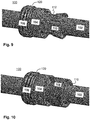
- FIG. 9 shows a perspective view of the clamping body 104 of the first exemplary seal assembly 100 according to the invention in a not fixed to a cable 102 position.
- the sealing member 106 with grooves 120 and the clamping body 104 with a plurality of clamping fingers or clamping tongues 110 can be seen in this view. Also visible is the recess 112, and the slots between the clamping fingers or clamping tongues 110th
- FIG. 10 shows a perspective view of the first exemplary seal assembly 100 according to the invention in a fixed position on the cable 102 position. As before in FIG. 9 In this view, the sealing part 106 with grooves 120 and the clamping body 104 can be seen. The clamping fingers or clamping tongues are covered by the clamping ring 108 and only partially visible.
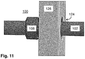
- FIG. 11 shows a perspective view of the first exemplary seal assembly 100 according to the invention in a fixed to a cable 102 position after installation in a cable gland 124 through a housing wall 126.
- the seal assembly 100 is substantially only clamping ring 108 visible; the remaining part is either covered by the clamping ring 108 or disposed within the cable gland 124.
Landscapes
- Engineering & Computer Science (AREA)
- Architecture (AREA)
- Civil Engineering (AREA)
- Structural Engineering (AREA)
- Installation Of Indoor Wiring (AREA)
- Cable Accessories (AREA)
Abstract
Description
- Die Erfindung betrifft eine Dichtungsanordnung für ein in ein Gehäuse eingeführtes Kabel.
- Elektrische Komponenten und Vorrichtungen sind häufig in geschlossenen Gehäusen angeordnet, z. B. um sie vor Umwelteinflüssen wie Staub, Flüssigkeiten oder Gasen zu schützen, die deren Funktion oder Lebensdauer beeinträchtigen könnten, oder zum Schutz vor unbeabsichtigter Berührung. In der Regel müssen die elektrischen Komponenten und Vorrichtungen über Leitungen mit elektrischer Energie versorgt werden, außerdem können Leitungen für Sensoren, Steuer- oder Datensignale zu den Komponenten und Vorrichtungen hinführen oder von diesen wegführen. Diese Leitungen oder Kabel müssen durch entsprechende Öffnungen im Gehäuse geführt werden, welche auch als Kabeldurchführungen bezeichnet werden. Die Kabeldurchführungen können bspw. als Bohrungen oder Ausstanzungen in einer Gehäusewand ausgeführt sein, welche einen größeren Durchmesser als der äußere Durchmesser eines Kabelmantels aufweisen, um das Einführen der Kabel zu erleichtern, welche unter Umständen außerdem einen Stecker oder anderen Anschluss an dem in das Gehäuse eingeführten Ende aufweisen können.
- Um die Dichtigkeit des Gehäuses wieder herzustellen müssen die Kabeldurchführungen mittels entsprechender Dichtmittel wieder verschlossen werden. Außerdem kann ein mechanischer Schutz des Kabels im Bereich der Kabeldurchführung gegen Scheuern oder Biegen mit unzulässig kleinen Biegeradien erwünscht sein. Darüber hinaus kann eine Fixierung des in das Gehäuse geführten Kabels gegen Verschiebung in axialer Richtung erforderlich sein.
- Eine aus dem Stand der Technik bekannte Dichtungsanordnung für eine Kabeldurchführung weist zwei Teile auf, welche von beiden Seiten einer Kabeldurchführung eines Gehäuses auf das durch die Kabeldurchführung geführte Kabel geschoben werden und dann miteinander lösbar oder unlösbar verbunden werden. Die Verbindung kann eine Schraub- oder Klemmverbindung umfassen und zusätzlich durch Kleben oder dergleichen gegen unbeabsichtigtes Lösen gesichert sein. Die Abdichtung des Innenraums des Gehäuses gegen das Eindringen von Festkörpern und Fluiden erfolgt dabei üblicherweise an zwei Stellen. Eine erste Dichtung ist zwischen Kabelmantel und Dichtungsanordnung vorgesehen, eine zweite Dichtung ist zwischen mindestens einem der beiden verbundenen Teile der Dichtungsanordnung und der Gehäusewand vorgesehen. Dadurch ergeben sich zwei Stellen, an denen die Dichtung versagen kann. Eine solche Dichtungsanordnung ist bspw. aus der
DE3604213A1 bekannt. - Die
DE3604213A1 zeigt eine zweiteilige Dichtungsanordnung, bei der eine Mutter auf ein Durchführungsteil geschraubt wird, wodurch Klemmzungen gegen den Kabelmantel gedrückt werden und dadurch das Kabel fixieren. Die Dichtung der Dichtungsanordnung gegen das Gehäuse wird durch die axial in Kabelrichtung beidseitig gegen die Gehäusewand drückenden Teile der Dichtungsanordnung bewirkt. Hierzu müssen die beiden miteinander verbundenen Teile einen Durchmesser aufweisen, welcher erheblich größer ist als das Loch der Kabeldurchführung. Außerdem muss die Länge des Durchführungsteils größer als die Wanddicke des Gehäuses sein, darf aber nicht zu groß sein, weil sonst die Mutter den konischen Teil, mit dem die Klemmzungen gegen den Kabelmantel gedrückt werden, vollständig zusammendrückt, ohne dass die axiale Dichtwirkung erzielt wird. Zudem ist es bei dieser Art Dichtungsanordnung erforderlich, dass der Montageort von beiden Seiten zugänglich ist. - Die
DE7729783U1 zeigt eine ähnliche Konstruktion, aber mit einem in dem Klemmbereich liegenden weichen Dichtungsteil, das beim Zusammenschrauben der beiden Teile der Dichtungsvorrichtung durch den konischen Teil der Mutter gegen den Kabelmantel gedrückt wird. - Die
DE19848216A1 zeigt ebenfalls eine ähnliche Konstruktion, wobei ein ringförmiges Weichteil in der Mutter angeordnet ist, welches beim Zusammenschrauben mit dem Dichtungskörper durch einen konischen Teil desselben gegen den Kabelmantel gedrückt wird. - Die
FR1282648A - Die
US3548079 zeigt eine zweiteilige Kabeldurchführung mit einem Dichtungskörper und einer Mutter, wobei die Mutter bei Verschraubung mit dem Dichtungskörper einen konischen Teil desselben gegen den Kabelmantel drückt. Die Dichtung gegenüber der Gehäusewand erfolgt durch einen Rastbereich des Dichtungskörpers sowie eine durch die Mutter auf diesen radial und axial wirkende Kraft. Auch bei dieser bekannten Dichtungsanordnung ist eine gewisse Mindesthärte der beiden Teile erforderlich, damit diese miteinander verschraubbar sind. Ebenfalls ist wegen der axialen Klemmung für unterschiedliche Wandstärken und außerdem für unterschiedliche Kabeldurchmesser die Bereitstellung einer entsprechenden Vielzahl an angepassten Dichtungsanordnungen erforderlich. - Wenngleich einige dieser bekannten Dichtungsanordnungen die Dichtung zwischen Kabel und Dichtungsanordnung sowie zwischen Dichtungsanordnung und Gehäuse mittels eines einzigen Dichtkörpers erzielen, so sind diese in der Regel sehr voluminös, weil eine ausreichende Abstützung der beiden miteinander verbundenen Teile gegen die Gehäusewand erreicht werden muss.
- Außerdem ist bei den bekannten Dichtungsanordnungen das vollständige Vormontieren und Fixieren der Dichtungsanordnung auf dem Kabel bereits vor der Montage nicht möglich. Ein derartiges Vormontieren bringt den Vorteil mit sich, dass in das Gehäuse eingeführte, vorkonfektionierte Kabel mit an korrekter Stelle auf dem Kabel platzierter Dichtungsanordnung im in der Gehäusedurchführung montierten Zustand innerhalb wie außerhalb des Gehäuses genau die richtige Länge aufweisen, um mit Komponenten, Bauteilen oder Baugruppen verbunden werden zu können. Es entfällt also das möglicherweise vor der endgültigen Befestigung der Dichtungsanordnung erforderliche Bewegen des Kabels, um die Anschlüsse herzustellen, wodurch auch das endgültige Befestigen der Dichtungsanordnung nicht vergessen werden kann.
- Hiervon ausgehend hat die vorliegende Erfindung die Aufgabe, eine Kabel-Dichtungsanordnung zu schaffen, welche eines oder mehrere der eingangs genannten Probleme überwindet oder zumindest verringert.
- Zur Lösung dieser Aufgabe schlägt die Erfindung nach einem ersten Aspekt eine auf einem Kabel axial fixierbare Dichtungsanordnung für eine Kabeldurchführung in ein Gehäuse vor, welche einen Klemmkörper und einen auf den Klemmkörper aufschiebbaren Klemmring umfasst.
- Mit dem Klemmkörper ist ein Dichtungsteil so verbunden, dass dieser zumindest im montierten Zustand der Dichtungsanordnung nicht oder zumindest nur unter großem Kraftaufwand von dem Klemmkörper lösbar ist. Die Verbindung kann eine kraft- und/oder formschlüssige Verbindung von Klemmkörper und Dichtungsteil umfassen, aber auch eine alternative oder zusätzliche stoffschlüssige Verbindung ist möglich, bspw. durch Anspritzen, Angießen, Verschweißen oder Kleben. Das Dichtungsteil ist vorzugsweise aus einem elastisch verformbaren ersten Material gefertigt, und der Klemmkörper ist aus einem zweiten elastisch verformbaren Material gefertigt. Das zweite Material kann eine größere Steifigkeit bzw. geringere Elastizität und/oder eine größere Härte aufweisen als das erste Material. Bei einer Variante sind Klemmkörper und Dichtungsanordnung ein einziges Teil, das aus einem Material mit einer geeigneten Elastizität und/oder Härte hergestellt ist.
- Zur Fixierung der Dichtungsanordnung auf dem Kabel wird der Klemmring axial über einen Teil des Klemmkörpers geschoben. Der Klemmring kann im montierten Zustand lösbar oder unlösbar fixiert sein, bspw. durch eine formschlüssige Verbindung mit einer entsprechenden Struktur des Klemmkörpers oder durch eine Klebeverbindung.
- Der Klemmkörper kann entlang eines Umfangs Klemmzungen oder Klemmfinger aufweisen, die durch den Klemmring radial aufeinander zu bewegt werden können. Die Klemmzungen oder Klemmfinger können außerdem zum Kabel weisende Strukturen aufweisen, welche bei aufgeschobenem Klemmring einen Mantel eines in die Dichtungsanordnung eingeführten Kabels lokal verformen und so eine formschlüssige Verbindung herstellen oder zumindest lokale Kraftspitzen erzeugen, die ein axiales Verschieben der Dichtungsanordnung verhindern oder erschweren. Diese Strukturen umfassen bspw. Stege, Zähne, Noppen oder Rillen.
- Bei einer Ausführung ist der Klemmring in einer montierten Position mit dem Klemmkörper formschlüssig so verbunden, dass der Klemmring nur unter Aufbringen einer vorbestimmten Mindestkraft lösbar ist.
- Bei einer Ausführung weist der Klemmring einen äußeren Durchmesser auf, welcher größer ist als eine Kabeldurchführung in ein Gehäuse. Eine axial auf das Kabel mit der Dichtungsanordnung wirkende Kraft, welche entgegen der Aufschieberichtung auf den Klemmring wirkt, bewirkt eine zunehmende Klemmwirkung der Klemmfinger oder Klemmzungen. Bei Überschreiten einer vorbestimmten Kraft kann der Klemmring sich aus der Montageposition lösen und es kann eine Verringerung der Klemmwirkung der Klemmfinger oder Klemmzungen eintreten, oder die Klemmwirkung wird aufgehoben.
- Diese Ausführung kann vorteilhaft sein, wenn eine axiale mechanische Zugbelastung in eine Richtung erwartet wird. In diesem Fall kann der Klemmring gegen ein Durchziehen des Kabels mit der Dichtungsanordnung durch die Kabeldurchführung sperren. Bei Überschreiten der vorbestimmten Kraft löst sich der Klemmring von den Klemmzungen oder Klemmfingern und gibt das Kabel frei. Das Kabel kann nun in der Dichtungsanordnung axial bewegt werden. Bei einer hinreichend großen axialen Bewegung des Kabels kann sich bspw. ein Steckverbinder aus einer Buchse lösen, wodurch die Gefahr des Reißens des Kabels verringert ist.
- Bei dieser Ausführung kann der Klemmring aber auch so montiert sein, dass eine axiale mechanische Zugbelastung eine Verstärkung der Klemmwirkung bewirkt.
- Im montierten Zustand ist das in eine Kabeldurchführung eines Gehäuses eingesetzte Dichtungsteil in einer Ebene radial gegen das Kabel und gegen die Kabeldurchführung wirkenden Kräften ausgesetzt. Die radial wirkenden Kräfte werden durch die Komprimierung zumindest von denjenigen Teilen des elastischen Dichtungsteils erzeugt, welche einen größeren Durchmesser als die Kabeldurchführung aufweisen und sich innerhalb der Kabeldurchführung befinden. Das elastische Dichtungsteil bewirkt so eine umlaufend radiale Dichtung gegen den Kabelmantel und die Kabeldurchführung. Unebenheiten der Oberfläche der Kabeldurchführung und/oder des Kabels werden durch das elastische Dichtungsteil ausgeglichen.
- Das Dichtungsteil kann auf einer zum Kabel weisenden Oberfläche und/oder einer zur Kabeldurchführung weisenden Oberfläche jeweils eine oder mehrere entlang eines Umfangs umlaufende Rillen oder Stege aufweisen. Diese können leichter verformbar sein und können sich Unebenheiten der Oberfläche der Kabeldurchführung und/oder des Kabelmantels noch besser anpassen als ein Dichtungsteil mit einer im Bereich der Dichtflächen glatten Oberfläche. Wenn mehrere umlaufende Rillen oder Stege vorhanden sind bilden diese mehrere hintereinander liegende Dichtungen. Wenn die Kabeldurchführung entlang ihres inneren Umfangs ebenfalls umlaufende Rillen oder Stege aufweist kann durch ineinandergreifende Rillen bzw. Stege von Dichtungsteil bzw. Kabeldurchführung eine Sicherung der Dichtungsanordnung gegen axiales Verschieben erzielt werden. Außerdem vergrößert sich die für die Dichtung zur Verfügung stehende Fläche.
- Bei einem Ausführungsbeispiel weist das Dichtungsteil eine axiale Länge auf, welche größer ist als eine Wanddicke eines Gehäuses, in das das Dichtungsteil eingesetzt ist. Die außerhalb der Wand mit der Kabeldurchführung befindlichen Bereiche des Dichtungsteils werden dabei nicht komprimiert und bewirken eine zusätzliche Sperre gegen eine axiale Verschiebung der montierten Dichtungsanordnung.
- Bei einem Ausführungsbeispiel ist an axial gegenüberliegenden Enden des Klemmkörpers jeweils ein Dichtungsteil vorgesehen, und mindestens ein Klemmring ist zwischen den Dichtungsteilen verschieblich gelagert. Die Dichtungsteile weisen einen Abstand voneinander auf, der im Wesentlichen einer Wanddicke der Kabeldurchführung entspricht. Im montierten Zustand sind dadurch beide Seiten der Kabeldurchführung gegen das Eindringen von Fluiden oder Festkörpern abgedichtet.
- Bei der Montage eines Kabels in eine Kabeldurchführung eines Gehäuses werden zunächst der Klemmkörper mit dem Dichtungsteil und der Klemmring auf das Kabel aufgeschoben und an eine gewünschte Position gebracht. Das Aufschieben erfolgt im Wesentlichen ohne radial wirkende Kräfte, so dass die für das axiale Aufschieben erforderliche Kraft klein ist. Ein Ende des Kabels kann dabei bereits durch die Kabeldurchführung in das Gehäuse eingeführt sein. Auf den an der gewünschten Position auf dem Kabel positionierten Klemmkörper wird der Klemmring geschoben, wodurch die Dichtungsanordnung auf dem Kabel fixiert wird. Die Dichtungsanordnung mit dem Kabel wird nun in die Kabeldurchführung eingeführt und so positioniert, dass das Dichtungsteil in der Kabeldurchführung zu liegen kommt. Dabei wird das Dichtungsteil komprimiert. Da die Dichtungsanordnung einen größeren Querschnitt aufweist als die Kabeldurchführung drückt das Dichtungsteil in radialer Richtung umlaufend gegen das Kabel und die Kabeldurchführung, so dass die Kabeldurchführung gegen das Eindringen von Fluiden und Festkörpern abgedichtet ist. Außerdem bewirkt die radial wirkende Kraft eine Fixierung der Dichtungsanordnung in der Kabeldurchführung. Eine zusätzliche Sicherung gegen axiales Verschieben kann vorgesehen sein, wenn die Klemmwirkung des Dichtungsteils in der Kabeldurchführung nicht ausreicht.
- Nachfolgend wird die Erfindung anhand einer Ausführungsform unter Bezugnahme auf die begleitenden Figuren exemplarisch näher erläutert. Alle Figuren sind rein schematisch und nicht maßstäblich. Es zeigen:
- Fig. 1
- eine schematische Schnittdarstellung einer ersten erfindungsgemäßen exemplarischen Dichtungsanordnung in einer nicht auf einem Kabel fixierten Lage,
- Fig. 2
- eine schematische Schnittdarstellung der ersten erfindungsgemäßen exemplarischen Dichtungsanordnung in einer auf dem Kabel fixierten Lage,
- Fig. 3
- eine schematische Schnittdarstellung der auf dem Kabel fixierten ersten erfindungsgemäßen exemplarischen Dichtungsanordnung nach Montage in einer Kabeldurchführung,
- Fig. 4
- eine schematische Schnittdarstellung der auf dem Kabel fixierten ersten erfindungsgemäßen exemplarischen Dichtungsanordnung nach Montage in einer Kabeldurchführung mit geringer Wanddicke,
- Fig. 5
- eine schematische Schnittdarstellung einer auf einem Kabel fixierten zweiten erfindungsgemäßen exemplarischen Dichtungsanordnung nach Montage in einer Kabeldurchführung,
- Fig. 6
- eine schematische Schnittdarstellung der auf dem Kabel fixierten zweiten erfindungsgemäßen exemplarischen Dichtungsanordnung nach Montage in einer Kabeldurchführung bei Einwirken einer Kraft in eine axiale Richtung,
- Fig. 7
- eine schematische Schnittdarstellung einer dritten erfindungsgemäßen exemplarischen Dichtungsanordnung in einer nicht auf einem Kabel fixierten Lage,
- Fig. 8
- eine schematische Schnittdarstellung der auf dem Kabel fixierten dritten erfindungsgemäßen exemplarischen Dichtungsanordnung nach Montage in einer Kabeldurchführung,
- Fig. 9
- eine perspektivische Ansicht eines Teils der ersten erfindungsgemäßen exemplarischen Dichtungsanordnung in einer nicht auf einem Kabel fixierten Lage,
- Fig. 10
- eine perspektivische Ansicht der ersten erfindungsgemäßen exemplarischen Dichtungsanordnung in einer auf dem Kabel fixierten Lage, und
- Fig. 11
- eine perspektivische Ansicht der ersten erfindungsgemäßen exemplarischen Dichtungsanordnung in einer nicht auf einem Kabel fixierten Lage nach Montage in einer Kabeldurchführung.
- Gleiche oder ähnliche Elemente sind in den Figuren mit gleichen oder ähnlichen Bezugszeichen versehen.
-
Figur 1 zeigt eine schematische Schnittdarstellung einer ersten erfindungsgemäßen exemplarischen Dichtungsanordnung 100 in einer nicht auf einem Kabel 102 fixierten Lage. Die Dichtungsanordnung umfasst einen Klemmkörper 104, mit welchem ein Dichtungsteil 106 verbunden ist. In dem in der Figur gezeigten exemplarischen Beispiel sind Dichtungsteil 106 und Klemmkörper 104 mittels einer formschlüssigen Verbindung 105 verbunden, hervorgehoben durch die gepunktete Ellipse. Andere Verbindungsarten wie Kleben, Schweißen, etc. oder Kombinationen unterschiedlicher Verbindungsarten sind ebenso denkbar. Die Dichtungsanordnung umfasst außerdem einen Klemmring 108. Klemmkörper 104 mit Dichtungsteil 106 sowie Klemmring 108 sind auf dem Kabel 102 in axialer Richtung beweglich und können so an eine gewünschte Position auf dem Kabel 102 gebracht werden. Der Klemmkörper 104 weist Klemmfinger oder Klemmzungen 110 auf, welche flexibel gegen die Oberfläche des Kabels 102 beweglich sind. Der Klemmkörper 104 weist außerdem eine oder mehrere Vertiefungen 112 auf, die im montierten Zustand mit einem oder mehreren entsprechenden radial nach innen vorspringenden Teilen 114 - hervorgehoben durch die gepunktete Ellipse - des Klemmrings 108 eine formschlüssige Verbindung eingehen. Die Vertiefung 112 kann ringförmig umlaufend ausgestaltet sein oder nur in einigen Bereichen des Klemmkörpers 104 ausgebildet sein. In letzterem Fall müssen die nach innen vorspringende Teile 114 des Klemmrings vor der Montage entsprechend ausgerichtet sein. Der Klemmring 108 kann aus einem flexiblen Material bestehen, um bei der Montage über die Klemmfinger oder Klemmzungen 110 geführt werden zu können. Zusätzlich kann der Klemmring 108 in axialer Richtung im Bereich des vorspringenden Teils 114 Einkerbungen oder Schlitze aufweisen (nicht in der Figur gezeigt), welche eine größere Beweglichkeit des bzw. der vorspringenden Teile 114 ermöglichen und dadurch die Montage erleichtern. Das Dichtungsteil 106 ist an einer nach außen weisenden äußeren Oberfläche 116 und an einer zu dem Kabel 102 weisenden inneren Oberfläche 118 mit radial umlaufenden Rillen 120 versehen. Äußere und/oder innere Oberfläche 116, 118 können auch ohne die Rillen 120 ausgeführt sein. -
Figur 2 zeigt eine schematische Schnittdarstellung der ersten erfindungsgemäßen exemplarischen Dichtungsanordnung 100 in einer auf dem Kabel 102 fixierten Lage. Der Klemmring 108 ist über die Klemmfinger oder Klemmzungen 110 geschoben und drückt diese gegen die Oberfläche des Kabels 102. Vorspringende Teile der Klemmfinger oder Klemmzungen 110 drücken dabei auf den Mantel des Kabels 102 und bilden mit den dabei entstehenden Vertiefungen im Kabelmantel eine formschlüssige Verbindung. Die vorspringenden Teile 114 des Klemmrings 108 sind in der oder den Vertiefungen 112 des Klemmkörpers 104 gelagert und bilden ebenfalls eine formschlüssige Verbindung (in der Figur in der gepunkteten Ellipse gezeigt). An der rechten Seite der Figur ist ein Ausschnitt einer Gehäusewand 126 mit einer Kabeldurchführung 124 dargestellt, in welcher die Dichtungsanordnung 100 montiert werden soll. -
Figur 3 zeigt eine schematische Schnittdarstellung der auf dem Kabel 102 fixierten ersten erfindungsgemäßen exemplarischen Dichtungsanordnung 100 ausFigur 2 nach Montage in einer Kabeldurchführung 124 durch eine Gehäusewand 126. Aus Gründen der besseren Übersichtlichkeit sind die meisten der Bezugszeichen der Dichtungsanordnung 100 weggelassen. Das Dichtungsteil 106 weist eine axiale Länge auf, die im Wesentlichen der Dicke der Gehäusewand 126 entspricht. Das Dichtungsteil 106 ist radial zusammendrückt, was in der Figur durch die verformten Rillen 120 angedeutet ist. Es ist leicht erkennbar, dass im Dichtungsteil 106 radial nach innen und außen Kräfte in einer Ebene mit der Gehäusewand wirken, die so die Abdichtung der Kabeldurchführung sicherstellen. -
Figur 4 zeigt eine schematische Schnittdarstellung der auf dem Kabel 102 fixierten ersten erfindungsgemäßen exemplarischen Dichtungsanordnung 100 ausFigur 2 nach Montage in einer Kabeldurchführung 124 mit geringerer Wanddicke. Auch hier sind aus Gründen der besseren Übersichtlichkeit die meisten der Bezugszeichen der Dichtungsanordnung 100 weggelassen. Es ist in der Figur klar erkennbar, dass der Rand des Dichtungsteils 106 sich nach dem Durchstecken durch die Kabeldurchführung 124 wieder ausgedehnt hat. Dadurch wird eine zusätzliche Sicherung gegen Herausziehen der Dichtungsanordnung 100 erzielt, weil zunächst wieder die Kraft für die Kompression des Dichtungsteils aufgebracht werden muss. Wenn die axiale Länge des Dichtungsteils 106 noch größer ist, können auf beiden Seiten der Kabeldurchführung 124 Teile des Dichtungsteils weitgehend unkomprimiert bleiben und so eine Sicherung gegen Verschieben in beide axiale Richtungen bilden. Die Kabeldurchführung 124 kann auf einer oder beiden Seiten eine Fase aufweisen (nicht in der Figur gezeigt), die das Einführen des Dichtungsteils 106 erleichtern. -
Figur 5 zeigt eine schematische Schnittdarstellung einer auf einem Kabel 102 fixierten zweiten erfindungsgemäßen exemplarischen Dichtungsanordnung 200 nach Montage in einer Kabeldurchführung 124. Auch hier sind aus Gründen der besseren Übersichtlichkeit die meisten der Bezugszeichen der Dichtungsanordnung 200 weggelassen; die Komponenten sind dieselben wie bei der Dichtungsanordnung 100. Bei dieser Ausführung weist der Klemmring 108 einen größeren Durchmesser als die Öffnung der Kabeldurchführung 124 auf, während der Klemmkörper 104 einen Durchmesser aufweist, der gleich groß oder kleiner als die Öffnung der Kabeldurchführung 124 ist. In der Figur liegt das Dichtungsteil 106 zentriert in der Kabeldurchführung 124. -
Figur 6 zeigt eine schematische Schnittdarstellung der auf dem Kabel 102 fixierten zweiten erfindungsgemäßen exemplarischen Dichtungsanordnung 200 nach Montage in einer Kabeldurchführung 124 bei Einwirken einer Kraft in eine axiale Richtung. Wie zuvor sind auch hier sind aus Gründen der besseren Übersichtlichkeit die meisten der Bezugszeichen der Dichtungsanordnung 200 weggelassen. Die Kraft und ihre Richtung sind durch den Pfeil 128 angedeutet. Die Dichtungsanordnung 100 ist bereits in Richtung der Kraft aus der inFigur 5 gezeigten Ausgangslage axial verschoben, so dass das Dichtungsteil 106 nicht mehr zentriert in der Kabeldurchführung liegt. Der Klemmring 208 liegt an der Gehäusewand 126 an. Bei Steigerung der Kraft können sich die vorspringenden Teile 114 des Klemmrings 208 aus der Vertiefung 112 des Klemmkörpers 104 lösen und den Klemmkörper 104 und damit das Kabel freigeben, so dass das Kabel und/oder der Klemmkörper der Kraft folgen können. Die für das Lösen des Klemmrings 208 vom Klemmkörper 104 erforderliche Kraft kann in gewissen Grenzen durch eine entsprechende Gestaltung der Rastkanten der Vertiefung 112 und der vorspringenden Teile 114 definiert eingestellt werden. In der Figur ist dies durch schräge Kanten angedeutet (in der Figur in dem gepunkteten Kreis gezeigt). -
Figur 7 zeigt eine schematische Schnittdarstellung einer dritten erfindungsgemäßen exemplarischen Dichtungsanordnung 300 in einer nicht auf einem Kabel 102 fixierten Lage. Die rechte Seite des Klemmkörpers 304 entspricht bis zu der strichpunktierten Linie A-A' dem Klemmkörper aus denFiguren 1 bis 5 . Klemmring 108 entspricht dem Klemmring aus denFiguren 1 bis 4 . Im Unterschied zu den zuvor beschriebenen Dichtungsanordnungen 100, 200 ist ein zweiter Dichtungsteil 306 an einem dem ersten Dichtungsteil 106 gegenüberliegenden Ende des Klemmkörpers 304 vorgesehen, in der Figur auf der linken Seite. Der zweite Dichtungsteil kann auf dieselbe Weise mit dem Klemmkörper 304 verbunden sein. Der Klemmring 108 ist zwischen den beiden Dichtungsteilen 106, 306 verschieblich angeordnet. Seine Elemente und deren Funktionsweise entsprechen den zuvor mit Bezug auf dieFiguren 1 bis 6 beschriebenen. -
Figur 8 zeigt eine schematische Schnittdarstellung der auf dem Kabel 102 fixierten dritten erfindungsgemäßen exemplarischen Dichtungsanordnung 300 nach Montage in einer Kabeldurchführung 124. Die Fixierung der Dichtungsanordnung 300 auf dem Kabel 102 erfolgt auf die zuvor bereits beschriebene Weise und wird an dieser Stelle nicht erneut beschrieben. Die Wanddicke der Gehäusewand 126 ist gegenüber derjenigen in den zuvor beschriebenen Figuren deutlich größer. Dichtungsanordnung 300 weist eine axiale Länge auf, welche der größeren Wanddicke im Wesentlichen entspricht, so dass die in der Kabeldurchführung 124 platzierte Dichtungsanordnung beidseitig bündig mit der Gehäusewand 136 abschließt. Diese Art Dichtungsanordnung kann verhindern, dass sich Fluide oder Festkörper in einer nur einseitig mit einer Dichtungsanordnung verschlossenen Kabeldurchführung sammeln und dort z.B. Korrosion oder andere unerwünschte Veränderungen von Materialien hervorrufen. -
Figur 9 zeigt eine perspektivische Ansicht des Klemmkörpers 104 der ersten erfindungsgemäßen exemplarischen Dichtungsanordnung 100 in einer nicht auf einem Kabel 102 fixierten Lage. Deutlich sind in dieser Ansicht das Dichtungsteil 106 mit Rillen 120 sowie der Klemmkörper 104 mit mehreren Klemmfingern oder Klemmzungen 110 erkennbar. Ebenfalls erkennbar ist die Vertiefung 112, sowie die Schlitze zwischen den Klemmfingern oder Klemmzungen 110. -
Figur 10 zeigt eine perspektivische Ansicht der ersten erfindungsgemäßen exemplarischen Dichtungsanordnung 100 in einer auf dem Kabel 102 fixierten Lage. Wie zuvor inFigur 9 sind in dieser Ansicht das Dichtungsteil 106 mit Rillen 120 sowie der Klemmkörper 104 erkennbar. Die Klemmfinger oder Klemmzungen sind durch den Klemmring 108 verdeckt und nur noch teilweise sichtbar. -
Figur 11 zeigt eine perspektivische Ansicht der ersten erfindungsgemäßen exemplarischen Dichtungsanordnung 100 in einer auf einem Kabel 102 fixierten Lage nach Montage in einer Kabeldurchführung 124 durch eine Gehäusewand 126. Von der Dichtungsanordnung 100 ist im Wesentlichen nur Klemmring 108 sichtbar; der übrige Teil ist entweder durch den Klemmring 108 verdeckt oder innerhalb der Kabeldurchführung 124 angeordnet. -
- 100
- Dichtungsanordnung
- 102
- Kabel
- 104
- Klemmkörper
- 105
- formschlüssige Verbindung
- 106
- Dichtungsteil
- 108
- Klemmring
- 110
- Klemmfinger / Klemmzunge
- 112
- Vertiefung
- 114
- vorspringender Teil
- 116
- äußere Oberfläche
- 118
- innere Oberfläche
- 120
- Rillen
- 124
- Kabeldurchführung
- 126
- Gehäusewand
- 128
- Kraft / Kraftrichtung
- 200
- Dichtungsanordnung
- 208
- Klemmring
- 300
- Dichtungsanordnung
- 304
- Klemmkörper
- 306
- Dichtungsteil
Claims (14)
- Auf einem Kabel (102) axial fixierbare Dichtungsanordnung (100; 200; 300) für eine Kabeldurchführung (124) in ein Gehäuse, umfassend:- einen Klemmkörper (104; 304) mit einem daran befestigten Dichtungsteil (106; 306), und- einen auf den Klemmkörper (104; 304) aufschiebbaren Klemmring (108; 208),wobei das Dichtungsteil (106; 306) aus einem elastisch verformbaren ersten Material gefertigt ist, und
wobei der Klemmkörper (104; 304) aus einem zweiten elastisch verformbaren Material gefertigt ist, wobei das zweite Material eine geringere Elastizität als das erste Material aufweist. - Dichtungsanordnung (100; 200; 300) nach Anspruch 1, wobei das Dichtungsteil (106; 306) im in die Kabeldurchführung (124) des Gehäuses montierten Zustand in einer Ebene radial gegen das Kabel (102) und gegen die Kabeldurchführung (124) in eine Gehäusewand (126) wirkenden Kräften ausgesetzt ist.
- Dichtungsanordnung (100; 200; 300) nach Anspruch 1 oder 2, wobei der Klemmkörper (104; 304) entlang eines Umfangs Klemmzungen oder Klemmfinger (110) aufweist, die durch den Klemmring (108; 208) radial aufeinander zu bewegt werden können.
- Dichtungsanordnung nach Anspruch 3, wobei die Klemmfinger oder Klemmzungen (110) auf einer zum Kabel (102) weisenden Seite Strukturen aufweisen, die bei aufgeschobenem Klemmring (108; 208) einen Mantel eines in die Dichtungsanordnung eingeführten Kabels (102) lokal verformen und so eine formschlüssige Verbindung herstellen oder zumindest lokale Kraftspitzen erzeugen, die ein axiales Verschieben der Dichtungsanordnung (100; 200; 300) verhindern oder erschweren.
- Dichtungsanordnung (100; 200; 300) nach einem oder mehreren der vorhergehenden Ansprüche, wobei das Dichtungsteil mit dem Klemmkörper stoffschlüssig, kraftschlüssig oder formschlüssig verbunden ist.
- Dichtungsanordnung (100; 200; 300) nach einem oder mehreren der vorhergehenden Ansprüche, wobei das Dichtungsteil (106; 306) auf einer zum Kabel (102) weisenden Oberfläche (118) und/oder einer zur Kabeldurchführung (124) weisenden Oberfläche (116) jeweils eine oder mehrere entlang eines Umfangs umlaufende Rillen oder Stege (120) aufweist.
- Dichtungsanordnung (100; 200) nach einem oder mehreren der vorhergehenden Ansprüche, wobei das Dichtungsteil (106) eine axiale Länge aufweist, welche größer ist als eine Wanddicke eines Gehäuses, in das das Dichtungsteil (106) eingesetzt ist.
- Dichtungsanordnung (100; 200; 300) nach einem oder mehreren der vorhergehenden Ansprüche, wobei der Klemmring (108; 208) in einer montierten Position mit dem Klemmkörper (104; 304) formschlüssig und/oder stoffschlüssig so verbunden ist, dass der Klemmring (108; 208) gegen Lösen gesichert ist.
- Dichtungsanordnung (100; 200; 300) nach einem oder mehreren der vorhergehenden Ansprüche, wobei der Klemmring (108; 208) in einer montierten Position mit dem Klemmkörper (104; 304) formschlüssig so verbunden ist, dass der Klemmring (108; 208) nur unter Aufbringen einer vorbestimmten Mindestkraft lösbar ist.
- Dichtungsanordnung (100; 200; 300) nach einem oder mehreren der vorhergehenden Ansprüche, wobei der Klemmring (208) einen äußeren Durchmesser aufweist, welcher größer ist als derjenige der Kabeldurchführung (124), und wobei eine axial entgegen der Aufschieberichtung auf den Klemmring (208) wirkende Kraft eine zunehmende Klemmwirkung der Klemmfinger oder Klemmzungen (110) bewirkt und/oder, bei Überschreiten einer vorbestimmten Kraft, ein Lösen des Klemmrings (208) aus einer Montageposition und dadurch eine Verringerung oder ein Verschwinden der Klemmwirkung der Klemmfinger oder Klemmzungen (110) bewirkt.
- Dichtungsanordnung (300) nach einem oder mehreren der vorhergehenden Ansprüche 1 bis 9, wobei an axial gegenüberliegenden Enden des Klemmkörpers (304) jeweils ein Dichtungsteil (106, 306) vorgesehen ist, und wobei mindestens ein Klemmring (108) zwischen den Dichtungsteilen (106, 306) verschieblich gelagert ist.
- Kabel (102) mit einer Dichtungsanordnung (100; 200; 300) nach einem oder mehreren der vorhergehenden Ansprüche, wobei die Dichtungsanordnung (100; 200; 300) auf dem Kabel (102) fixiert ist.
- Elektrische Einrichtung mit einem Gehäuse, wobei wenigstens ein Kabel (102) nach Anspruch 12 durch das Gehäuse in dessen Inneres geführt ist.
- Verfahren zur Abdichtung einer Kabeldurchführung (124) eines Gehäuses, umfassend:- Aufschieben und Fixieren einer Dichtungsanordnung (100; 200; 300) nach einem oder mehreren der Ansprüche 1 bis 11 auf einem in das Gehäuse einzuführenden Kabel (102), und- Einführen des Kabels (102) und der Dichtungsanordnung (100; 200; 300) in die Kabeldurchführung (124) des Gehäuses, wobei mindestens ein Dichtungsteil (106; 306) der Dichtungsanordnung (100; 200; 300) komprimiert wird und radial umlaufend gegen die Oberfläche eines Kabelmantels sowie die Oberfläche der Kabeldurchführung (124) gepresst wird.
Priority Applications (1)
| Application Number | Priority Date | Filing Date | Title |
|---|---|---|---|
| EP18305326.3A EP3544132B1 (de) | 2018-03-23 | 2018-03-23 | Axial fixierbare dichtungsanordnung für eine kabeldurchführung |
Applications Claiming Priority (1)
| Application Number | Priority Date | Filing Date | Title |
|---|---|---|---|
| EP18305326.3A EP3544132B1 (de) | 2018-03-23 | 2018-03-23 | Axial fixierbare dichtungsanordnung für eine kabeldurchführung |
Publications (2)
| Publication Number | Publication Date |
|---|---|
| EP3544132A1 true EP3544132A1 (de) | 2019-09-25 |
| EP3544132B1 EP3544132B1 (de) | 2021-08-04 |
Family
ID=61868477
Family Applications (1)
| Application Number | Title | Priority Date | Filing Date |
|---|---|---|---|
| EP18305326.3A Active EP3544132B1 (de) | 2018-03-23 | 2018-03-23 | Axial fixierbare dichtungsanordnung für eine kabeldurchführung |
Country Status (1)
| Country | Link |
|---|---|
| EP (1) | EP3544132B1 (de) |
Cited By (2)
| Publication number | Priority date | Publication date | Assignee | Title |
|---|---|---|---|---|
| US11688967B2 (en) | 2019-11-21 | 2023-06-27 | KYOCERA AVX Components Corporation | Wire termination device for coupling a wire to a feedthrough device and system including the same |
| US20230245801A1 (en) * | 2020-08-13 | 2023-08-03 | Auto-Kabel Management Gmbh | Gasket for an Electric Cable |
Citations (6)
| Publication number | Priority date | Publication date | Assignee | Title |
|---|---|---|---|---|
| FR1282648A (fr) | 1960-12-14 | 1962-01-27 | Perfectionnements aux dispositifs de traversée étanche pour canalisations électriques | |
| US3548079A (en) | 1969-05-16 | 1970-12-15 | Raychem Corp | Bulkhead feedthrough |
| DE7729783U1 (de) | 1977-09-26 | 1978-02-16 | Schuchardt, Helmut, 6920 Sinsheim | Kabel-Verschraubung mit Zugentlastung, auswechselbarem Biegeschutz und Druckschraubenabdichtung |
| DE3604213A1 (de) | 1986-02-11 | 1987-08-13 | Hermann Holzmann | Kabelverschraubung |
| DE19848216A1 (de) | 1998-10-20 | 2000-05-18 | Kleinhuis Hermann Gmbh | Verschraubung zur Ein- und Durchführung sowie Abdichtung von Kabeln, Leitungen, Schläuchen und dergleichen |
| DE202013003600U1 (de) * | 2013-04-17 | 2014-07-21 | Wiska Hoppmann & Mulsow Gmbh | Kabelverschraubung mit integralem Gelenk |
-
2018
- 2018-03-23 EP EP18305326.3A patent/EP3544132B1/de active Active
Patent Citations (6)
| Publication number | Priority date | Publication date | Assignee | Title |
|---|---|---|---|---|
| FR1282648A (fr) | 1960-12-14 | 1962-01-27 | Perfectionnements aux dispositifs de traversée étanche pour canalisations électriques | |
| US3548079A (en) | 1969-05-16 | 1970-12-15 | Raychem Corp | Bulkhead feedthrough |
| DE7729783U1 (de) | 1977-09-26 | 1978-02-16 | Schuchardt, Helmut, 6920 Sinsheim | Kabel-Verschraubung mit Zugentlastung, auswechselbarem Biegeschutz und Druckschraubenabdichtung |
| DE3604213A1 (de) | 1986-02-11 | 1987-08-13 | Hermann Holzmann | Kabelverschraubung |
| DE19848216A1 (de) | 1998-10-20 | 2000-05-18 | Kleinhuis Hermann Gmbh | Verschraubung zur Ein- und Durchführung sowie Abdichtung von Kabeln, Leitungen, Schläuchen und dergleichen |
| DE202013003600U1 (de) * | 2013-04-17 | 2014-07-21 | Wiska Hoppmann & Mulsow Gmbh | Kabelverschraubung mit integralem Gelenk |
Cited By (3)
| Publication number | Priority date | Publication date | Assignee | Title |
|---|---|---|---|---|
| US11688967B2 (en) | 2019-11-21 | 2023-06-27 | KYOCERA AVX Components Corporation | Wire termination device for coupling a wire to a feedthrough device and system including the same |
| US20230245801A1 (en) * | 2020-08-13 | 2023-08-03 | Auto-Kabel Management Gmbh | Gasket for an Electric Cable |
| US11881331B2 (en) * | 2020-08-13 | 2024-01-23 | Auto-Kabel Management Gmbh | Gasket for an electric cable |
Also Published As
| Publication number | Publication date |
|---|---|
| EP3544132B1 (de) | 2021-08-04 |
Similar Documents
| Publication | Publication Date | Title |
|---|---|---|
| EP0598261B1 (de) | Kabelverschraubung für Erdungs- oder Abschirm-Kabel | |
| DE102017121459B4 (de) | Kabelabdichtung sowie Anordnung mit einem Gehäuse | |
| DE112008004188T5 (de) | Grommet | |
| EP2793334B1 (de) | Kabelverschraubung mit integralem Gelenk | |
| EP1710886B1 (de) | Kabeldurchführung | |
| EP3963217A1 (de) | Befestigungsanordnung mit dämpfungswirkung und bauteilverbindung mit der befestigungsanordnung | |
| EP3266083A1 (de) | Dichtungstülle und kabeldurchführung mit einer dichtungstülle | |
| WO1995001528A1 (de) | Vorrichtung zur abgedichteten verlegung von rohren, leitungen und dergleichen | |
| EP3329566B1 (de) | Explosionsgeschützte anordnung und verfahren zu deren herstellung | |
| AT3080U1 (de) | Vorrichtung zum verbinden eines rohrstutzens, rohrförmigen armaturenteils oder fittings mit einem rohr | |
| EP3649712B1 (de) | Kabeldurchführungseinrichtung | |
| EP2784880A1 (de) | Kabeldurchführung | |
| EP2518849B1 (de) | Gehäusedurchführung (kabelverschraubung) | |
| EP3544132B1 (de) | Axial fixierbare dichtungsanordnung für eine kabeldurchführung | |
| EP1048101B1 (de) | Kabelmuffe aus einem umhüllungskörper und mindestens einem stirnseitigen dichtungskörper | |
| DE102013218733A1 (de) | Kabeldurchführungseinrichtung | |
| EP0402653A2 (de) | Kabeleinführungsdichtung | |
| EP3871295A1 (de) | Elektrischer Stecker, elektrisches Gerät, elektrische Steckverbindung und Verfahren zur Herstellung eines elektrischen Geräts | |
| DE10349440B4 (de) | Dichte Wanddurchführung mit Zugentlastung | |
| EP0695008A1 (de) | Universelle Kabelklemmvorrichtung | |
| EP1673841B1 (de) | Emv-dichte haltevorrichtung für kabel | |
| DE102015220685B4 (de) | Zugentlastungselement für eine Leitung, Aufnahmeeinrichtung, Zugentlastungsvorrichtung und Gehäuse | |
| CH689683A5 (de) | Gehaeuse mit einer Vorrichtung zur Kabelzugentlastung. | |
| EP4127494B1 (de) | Druckmutter | |
| DE3937888C2 (de) |
Legal Events
| Date | Code | Title | Description |
|---|---|---|---|
| PUAI | Public reference made under article 153(3) epc to a published international application that has entered the european phase |
Free format text: ORIGINAL CODE: 0009012 |
|
| STAA | Information on the status of an ep patent application or granted ep patent |
Free format text: STATUS: THE APPLICATION HAS BEEN PUBLISHED |
|
| AK | Designated contracting states |
Kind code of ref document: A1 Designated state(s): AL AT BE BG CH CY CZ DE DK EE ES FI FR GB GR HR HU IE IS IT LI LT LU LV MC MK MT NL NO PL PT RO RS SE SI SK SM TR |
|
| AX | Request for extension of the european patent |
Extension state: BA ME |
|
| STAA | Information on the status of an ep patent application or granted ep patent |
Free format text: STATUS: REQUEST FOR EXAMINATION WAS MADE |
|
| 17P | Request for examination filed |
Effective date: 20200325 |
|
| RBV | Designated contracting states (corrected) |
Designated state(s): AL AT BE BG CH CY CZ DE DK EE ES FI FR GB GR HR HU IE IS IT LI LT LU LV MC MK MT NL NO PL PT RO RS SE SI SK SM TR |
|
| STAA | Information on the status of an ep patent application or granted ep patent |
Free format text: STATUS: EXAMINATION IS IN PROGRESS |
|
| 17Q | First examination report despatched |
Effective date: 20200730 |
|
| GRAP | Despatch of communication of intention to grant a patent |
Free format text: ORIGINAL CODE: EPIDOSNIGR1 |
|
| STAA | Information on the status of an ep patent application or granted ep patent |
Free format text: STATUS: GRANT OF PATENT IS INTENDED |
|
| RIC1 | Information provided on ipc code assigned before grant |
Ipc: F16L 5/02 20060101ALN20210205BHEP Ipc: H02G 3/06 20060101AFI20210205BHEP Ipc: H02G 3/22 20060101ALI20210205BHEP |
|
| RIC1 | Information provided on ipc code assigned before grant |
Ipc: H02G 3/06 20060101AFI20210212BHEP Ipc: F16L 5/02 20060101ALN20210212BHEP Ipc: H02G 3/22 20060101ALI20210212BHEP |
|
| INTG | Intention to grant announced |
Effective date: 20210301 |
|
| GRAS | Grant fee paid |
Free format text: ORIGINAL CODE: EPIDOSNIGR3 |
|
| GRAA | (expected) grant |
Free format text: ORIGINAL CODE: 0009210 |
|
| STAA | Information on the status of an ep patent application or granted ep patent |
Free format text: STATUS: THE PATENT HAS BEEN GRANTED |
|
| AK | Designated contracting states |
Kind code of ref document: B1 Designated state(s): AL AT BE BG CH CY CZ DE DK EE ES FI FR GB GR HR HU IE IS IT LI LT LU LV MC MK MT NL NO PL PT RO RS SE SI SK SM TR |
|
| REG | Reference to a national code |
Ref country code: GB Ref legal event code: FG4D Free format text: NOT ENGLISH |
|
| REG | Reference to a national code |
Ref country code: AT Ref legal event code: REF Ref document number: 1417979 Country of ref document: AT Kind code of ref document: T Effective date: 20210815 |
|
| REG | Reference to a national code |
Ref country code: CH Ref legal event code: EP |
|
| REG | Reference to a national code |
Ref country code: DE Ref legal event code: R096 Ref document number: 502018006413 Country of ref document: DE |
|
| REG | Reference to a national code |
Ref country code: IE Ref legal event code: FG4D Free format text: LANGUAGE OF EP DOCUMENT: GERMAN |
|
| REG | Reference to a national code |
Ref country code: LT Ref legal event code: MG9D |
|
| REG | Reference to a national code |
Ref country code: NL Ref legal event code: MP Effective date: 20210804 |
|
| PG25 | Lapsed in a contracting state [announced via postgrant information from national office to epo] |
Ref country code: NO Free format text: LAPSE BECAUSE OF FAILURE TO SUBMIT A TRANSLATION OF THE DESCRIPTION OR TO PAY THE FEE WITHIN THE PRESCRIBED TIME-LIMIT Effective date: 20211104 Ref country code: PT Free format text: LAPSE BECAUSE OF FAILURE TO SUBMIT A TRANSLATION OF THE DESCRIPTION OR TO PAY THE FEE WITHIN THE PRESCRIBED TIME-LIMIT Effective date: 20211206 Ref country code: LT Free format text: LAPSE BECAUSE OF FAILURE TO SUBMIT A TRANSLATION OF THE DESCRIPTION OR TO PAY THE FEE WITHIN THE PRESCRIBED TIME-LIMIT Effective date: 20210804 Ref country code: BG Free format text: LAPSE BECAUSE OF FAILURE TO SUBMIT A TRANSLATION OF THE DESCRIPTION OR TO PAY THE FEE WITHIN THE PRESCRIBED TIME-LIMIT Effective date: 20211104 Ref country code: RS Free format text: LAPSE BECAUSE OF FAILURE TO SUBMIT A TRANSLATION OF THE DESCRIPTION OR TO PAY THE FEE WITHIN THE PRESCRIBED TIME-LIMIT Effective date: 20210804 Ref country code: SE Free format text: LAPSE BECAUSE OF FAILURE TO SUBMIT A TRANSLATION OF THE DESCRIPTION OR TO PAY THE FEE WITHIN THE PRESCRIBED TIME-LIMIT Effective date: 20210804 Ref country code: HR Free format text: LAPSE BECAUSE OF FAILURE TO SUBMIT A TRANSLATION OF THE DESCRIPTION OR TO PAY THE FEE WITHIN THE PRESCRIBED TIME-LIMIT Effective date: 20210804 Ref country code: FI Free format text: LAPSE BECAUSE OF FAILURE TO SUBMIT A TRANSLATION OF THE DESCRIPTION OR TO PAY THE FEE WITHIN THE PRESCRIBED TIME-LIMIT Effective date: 20210804 Ref country code: ES Free format text: LAPSE BECAUSE OF FAILURE TO SUBMIT A TRANSLATION OF THE DESCRIPTION OR TO PAY THE FEE WITHIN THE PRESCRIBED TIME-LIMIT Effective date: 20210804 |
|
| PG25 | Lapsed in a contracting state [announced via postgrant information from national office to epo] |
Ref country code: PL Free format text: LAPSE BECAUSE OF FAILURE TO SUBMIT A TRANSLATION OF THE DESCRIPTION OR TO PAY THE FEE WITHIN THE PRESCRIBED TIME-LIMIT Effective date: 20210804 Ref country code: LV Free format text: LAPSE BECAUSE OF FAILURE TO SUBMIT A TRANSLATION OF THE DESCRIPTION OR TO PAY THE FEE WITHIN THE PRESCRIBED TIME-LIMIT Effective date: 20210804 Ref country code: GR Free format text: LAPSE BECAUSE OF FAILURE TO SUBMIT A TRANSLATION OF THE DESCRIPTION OR TO PAY THE FEE WITHIN THE PRESCRIBED TIME-LIMIT Effective date: 20211105 |
|
| PG25 | Lapsed in a contracting state [announced via postgrant information from national office to epo] |
Ref country code: NL Free format text: LAPSE BECAUSE OF FAILURE TO SUBMIT A TRANSLATION OF THE DESCRIPTION OR TO PAY THE FEE WITHIN THE PRESCRIBED TIME-LIMIT Effective date: 20210804 |
|
| PG25 | Lapsed in a contracting state [announced via postgrant information from national office to epo] |
Ref country code: DK Free format text: LAPSE BECAUSE OF FAILURE TO SUBMIT A TRANSLATION OF THE DESCRIPTION OR TO PAY THE FEE WITHIN THE PRESCRIBED TIME-LIMIT Effective date: 20210804 |
|
| REG | Reference to a national code |
Ref country code: DE Ref legal event code: R097 Ref document number: 502018006413 Country of ref document: DE |
|
| PG25 | Lapsed in a contracting state [announced via postgrant information from national office to epo] |
Ref country code: SM Free format text: LAPSE BECAUSE OF FAILURE TO SUBMIT A TRANSLATION OF THE DESCRIPTION OR TO PAY THE FEE WITHIN THE PRESCRIBED TIME-LIMIT Effective date: 20210804 Ref country code: SK Free format text: LAPSE BECAUSE OF FAILURE TO SUBMIT A TRANSLATION OF THE DESCRIPTION OR TO PAY THE FEE WITHIN THE PRESCRIBED TIME-LIMIT Effective date: 20210804 Ref country code: RO Free format text: LAPSE BECAUSE OF FAILURE TO SUBMIT A TRANSLATION OF THE DESCRIPTION OR TO PAY THE FEE WITHIN THE PRESCRIBED TIME-LIMIT Effective date: 20210804 Ref country code: EE Free format text: LAPSE BECAUSE OF FAILURE TO SUBMIT A TRANSLATION OF THE DESCRIPTION OR TO PAY THE FEE WITHIN THE PRESCRIBED TIME-LIMIT Effective date: 20210804 Ref country code: CZ Free format text: LAPSE BECAUSE OF FAILURE TO SUBMIT A TRANSLATION OF THE DESCRIPTION OR TO PAY THE FEE WITHIN THE PRESCRIBED TIME-LIMIT Effective date: 20210804 Ref country code: AL Free format text: LAPSE BECAUSE OF FAILURE TO SUBMIT A TRANSLATION OF THE DESCRIPTION OR TO PAY THE FEE WITHIN THE PRESCRIBED TIME-LIMIT Effective date: 20210804 |
|
| PLBE | No opposition filed within time limit |
Free format text: ORIGINAL CODE: 0009261 |
|
| STAA | Information on the status of an ep patent application or granted ep patent |
Free format text: STATUS: NO OPPOSITION FILED WITHIN TIME LIMIT |
|
| 26N | No opposition filed |
Effective date: 20220506 |
|
| PG25 | Lapsed in a contracting state [announced via postgrant information from national office to epo] |
Ref country code: SI Free format text: LAPSE BECAUSE OF FAILURE TO SUBMIT A TRANSLATION OF THE DESCRIPTION OR TO PAY THE FEE WITHIN THE PRESCRIBED TIME-LIMIT Effective date: 20210804 |
|
| PG25 | Lapsed in a contracting state [announced via postgrant information from national office to epo] |
Ref country code: MC Free format text: LAPSE BECAUSE OF FAILURE TO SUBMIT A TRANSLATION OF THE DESCRIPTION OR TO PAY THE FEE WITHIN THE PRESCRIBED TIME-LIMIT Effective date: 20210804 |
|
| REG | Reference to a national code |
Ref country code: CH Ref legal event code: PL |
|
| GBPC | Gb: european patent ceased through non-payment of renewal fee |
Effective date: 20220323 |
|
| REG | Reference to a national code |
Ref country code: BE Ref legal event code: MM Effective date: 20220331 |
|
| PG25 | Lapsed in a contracting state [announced via postgrant information from national office to epo] |
Ref country code: LU Free format text: LAPSE BECAUSE OF NON-PAYMENT OF DUE FEES Effective date: 20220323 Ref country code: LI Free format text: LAPSE BECAUSE OF NON-PAYMENT OF DUE FEES Effective date: 20220331 Ref country code: IE Free format text: LAPSE BECAUSE OF NON-PAYMENT OF DUE FEES Effective date: 20220323 Ref country code: GB Free format text: LAPSE BECAUSE OF NON-PAYMENT OF DUE FEES Effective date: 20220323 Ref country code: CH Free format text: LAPSE BECAUSE OF NON-PAYMENT OF DUE FEES Effective date: 20220331 |
|
| PG25 | Lapsed in a contracting state [announced via postgrant information from national office to epo] |
Ref country code: BE Free format text: LAPSE BECAUSE OF NON-PAYMENT OF DUE FEES Effective date: 20220331 |
|
| PG25 | Lapsed in a contracting state [announced via postgrant information from national office to epo] |
Ref country code: MK Free format text: LAPSE BECAUSE OF FAILURE TO SUBMIT A TRANSLATION OF THE DESCRIPTION OR TO PAY THE FEE WITHIN THE PRESCRIBED TIME-LIMIT Effective date: 20210804 Ref country code: CY Free format text: LAPSE BECAUSE OF FAILURE TO SUBMIT A TRANSLATION OF THE DESCRIPTION OR TO PAY THE FEE WITHIN THE PRESCRIBED TIME-LIMIT Effective date: 20210804 |
|
| REG | Reference to a national code |
Ref country code: AT Ref legal event code: MM01 Ref document number: 1417979 Country of ref document: AT Kind code of ref document: T Effective date: 20230323 |
|
| PG25 | Lapsed in a contracting state [announced via postgrant information from national office to epo] |
Ref country code: HU Free format text: LAPSE BECAUSE OF FAILURE TO SUBMIT A TRANSLATION OF THE DESCRIPTION OR TO PAY THE FEE WITHIN THE PRESCRIBED TIME-LIMIT; INVALID AB INITIO Effective date: 20180323 |
|
| PG25 | Lapsed in a contracting state [announced via postgrant information from national office to epo] |
Ref country code: AT Free format text: LAPSE BECAUSE OF NON-PAYMENT OF DUE FEES Effective date: 20230323 |
|
| PG25 | Lapsed in a contracting state [announced via postgrant information from national office to epo] |
Ref country code: AT Free format text: LAPSE BECAUSE OF NON-PAYMENT OF DUE FEES Effective date: 20230323 |
|
| PG25 | Lapsed in a contracting state [announced via postgrant information from national office to epo] |
Ref country code: MT Free format text: LAPSE BECAUSE OF FAILURE TO SUBMIT A TRANSLATION OF THE DESCRIPTION OR TO PAY THE FEE WITHIN THE PRESCRIBED TIME-LIMIT Effective date: 20210804 |
|
| PG25 | Lapsed in a contracting state [announced via postgrant information from national office to epo] |
Ref country code: TR Free format text: LAPSE BECAUSE OF FAILURE TO SUBMIT A TRANSLATION OF THE DESCRIPTION OR TO PAY THE FEE WITHIN THE PRESCRIBED TIME-LIMIT Effective date: 20210804 |
|
| PGFP | Annual fee paid to national office [announced via postgrant information from national office to epo] |
Ref country code: DE Payment date: 20260319 Year of fee payment: 9 |
|
| PGFP | Annual fee paid to national office [announced via postgrant information from national office to epo] |
Ref country code: AT Payment date: 20260410 Year of fee payment: 5 |
|
| PGFP | Annual fee paid to national office [announced via postgrant information from national office to epo] |
Ref country code: IT Payment date: 20260324 Year of fee payment: 9 |
|
| PGFP | Annual fee paid to national office [announced via postgrant information from national office to epo] |
Ref country code: FR Payment date: 20260320 Year of fee payment: 9 |