EP3543990A1 - Household appliance with user interface - Google Patents
Household appliance with user interface Download PDFInfo
- Publication number
- EP3543990A1 EP3543990A1 EP19163750.3A EP19163750A EP3543990A1 EP 3543990 A1 EP3543990 A1 EP 3543990A1 EP 19163750 A EP19163750 A EP 19163750A EP 3543990 A1 EP3543990 A1 EP 3543990A1
- Authority
- EP
- European Patent Office
- Prior art keywords
- treatment
- household appliance
- video projector
- housing
- display area
- Prior art date
- Legal status (The legal status is an assumption and is not a legal conclusion. Google has not performed a legal analysis and makes no representation as to the accuracy of the status listed.)
- Granted
Links
Images




Classifications
-
- G—PHYSICS
- G09—EDUCATION; CRYPTOGRAPHY; DISPLAY; ADVERTISING; SEALS
- G09F—DISPLAYING; ADVERTISING; SIGNS; LABELS OR NAME-PLATES; SEALS
- G09F19/00—Advertising or display means not otherwise provided for
- G09F19/12—Advertising or display means not otherwise provided for using special optical effects
- G09F19/18—Advertising or display means not otherwise provided for using special optical effects involving the use of optical projection means, e.g. projection of images on clouds
-
- A—HUMAN NECESSITIES
- A47—FURNITURE; DOMESTIC ARTICLES OR APPLIANCES; COFFEE MILLS; SPICE MILLS; SUCTION CLEANERS IN GENERAL
- A47L—DOMESTIC WASHING OR CLEANING; SUCTION CLEANERS IN GENERAL
- A47L15/00—Washing or rinsing machines for crockery or tableware
- A47L15/42—Details
- A47L15/4293—Arrangements for programme selection, e.g. control panels; Indication of the selected programme, programme progress or other parameters of the programme, e.g. by using display panels
-
- A—HUMAN NECESSITIES
- A47—FURNITURE; DOMESTIC ARTICLES OR APPLIANCES; COFFEE MILLS; SPICE MILLS; SUCTION CLEANERS IN GENERAL
- A47L—DOMESTIC WASHING OR CLEANING; SUCTION CLEANERS IN GENERAL
- A47L15/00—Washing or rinsing machines for crockery or tableware
- A47L15/42—Details
- A47L15/4295—Arrangements for detecting or measuring the condition of the crockery or tableware, e.g. nature or quantity
-
- D—TEXTILES; PAPER
- D06—TREATMENT OF TEXTILES OR THE LIKE; LAUNDERING; FLEXIBLE MATERIALS NOT OTHERWISE PROVIDED FOR
- D06F—LAUNDERING, DRYING, IRONING, PRESSING OR FOLDING TEXTILE ARTICLES
- D06F34/00—Details of control systems for washing machines, washer-dryers or laundry dryers
- D06F34/28—Arrangements for program selection, e.g. control panels therefor; Arrangements for indicating program parameters, e.g. the selected program or its progress
- D06F34/32—Arrangements for program selection, e.g. control panels therefor; Arrangements for indicating program parameters, e.g. the selected program or its progress characterised by graphical features, e.g. touchscreens
-
- F—MECHANICAL ENGINEERING; LIGHTING; HEATING; WEAPONS; BLASTING
- F24—HEATING; RANGES; VENTILATING
- F24C—DOMESTIC STOVES OR RANGES ; DETAILS OF DOMESTIC STOVES OR RANGES, OF GENERAL APPLICATION
- F24C7/00—Stoves or ranges heated by electric energy
- F24C7/08—Arrangement or mounting of control or safety devices
- F24C7/082—Arrangement or mounting of control or safety devices on ranges, e.g. control panels, illumination
-
- F—MECHANICAL ENGINEERING; LIGHTING; HEATING; WEAPONS; BLASTING
- F25—REFRIGERATION OR COOLING; COMBINED HEATING AND REFRIGERATION SYSTEMS; HEAT PUMP SYSTEMS; MANUFACTURE OR STORAGE OF ICE; LIQUEFACTION SOLIDIFICATION OF GASES
- F25D—REFRIGERATORS; COLD ROOMS; ICE-BOXES; COOLING OR FREEZING APPARATUS NOT OTHERWISE PROVIDED FOR
- F25D29/00—Arrangement or mounting of control or safety devices
- F25D29/005—Mounting of control devices
-
- G—PHYSICS
- G06—COMPUTING OR CALCULATING; COUNTING
- G06F—ELECTRIC DIGITAL DATA PROCESSING
- G06F3/00—Input arrangements for transferring data to be processed into a form capable of being handled by the computer; Output arrangements for transferring data from processing unit to output unit, e.g. interface arrangements
- G06F3/01—Input arrangements or combined input and output arrangements for interaction between user and computer
- G06F3/017—Gesture based interaction, e.g. based on a set of recognized hand gestures
-
- G—PHYSICS
- G06—COMPUTING OR CALCULATING; COUNTING
- G06F—ELECTRIC DIGITAL DATA PROCESSING
- G06F3/00—Input arrangements for transferring data to be processed into a form capable of being handled by the computer; Output arrangements for transferring data from processing unit to output unit, e.g. interface arrangements
- G06F3/01—Input arrangements or combined input and output arrangements for interaction between user and computer
- G06F3/03—Arrangements for converting the position or the displacement of a member into a coded form
- G06F3/041—Digitisers, e.g. for touch screens or touch pads, characterised by the transducing means
- G06F3/042—Digitisers, e.g. for touch screens or touch pads, characterised by the transducing means by opto-electronic means
- G06F3/0425—Digitisers, e.g. for touch screens or touch pads, characterised by the transducing means by opto-electronic means using a single imaging device like a video camera for tracking the absolute position of a single or a plurality of objects with respect to an imaged reference surface, e.g. video camera imaging a display or a projection screen, a table or a wall surface, on which a computer generated image is displayed or projected
- G06F3/0426—Digitisers, e.g. for touch screens or touch pads, characterised by the transducing means by opto-electronic means using a single imaging device like a video camera for tracking the absolute position of a single or a plurality of objects with respect to an imaged reference surface, e.g. video camera imaging a display or a projection screen, a table or a wall surface, on which a computer generated image is displayed or projected tracking fingers with respect to a virtual keyboard projected or printed on the surface
-
- G—PHYSICS
- G09—EDUCATION; CRYPTOGRAPHY; DISPLAY; ADVERTISING; SEALS
- G09F—DISPLAYING; ADVERTISING; SIGNS; LABELS OR NAME-PLATES; SEALS
- G09F23/00—Advertising on or in specific articles, e.g. ashtrays, letter-boxes
- G09F23/0058—Advertising on or in specific articles, e.g. ashtrays, letter-boxes on electrical household appliances, e.g. on a dishwasher, a washing machine or a refrigerator
-
- A—HUMAN NECESSITIES
- A47—FURNITURE; DOMESTIC ARTICLES OR APPLIANCES; COFFEE MILLS; SPICE MILLS; SUCTION CLEANERS IN GENERAL
- A47L—DOMESTIC WASHING OR CLEANING; SUCTION CLEANERS IN GENERAL
- A47L15/00—Washing or rinsing machines for crockery or tableware
- A47L15/42—Details
- A47L15/4251—Details of the casing
-
- D—TEXTILES; PAPER
- D06—TREATMENT OF TEXTILES OR THE LIKE; LAUNDERING; FLEXIBLE MATERIALS NOT OTHERWISE PROVIDED FOR
- D06F—LAUNDERING, DRYING, IRONING, PRESSING OR FOLDING TEXTILE ARTICLES
- D06F2103/00—Parameters monitored or detected for the control of domestic laundry washing machines, washer-dryers or laundry dryers
-
- D—TEXTILES; PAPER
- D06—TREATMENT OF TEXTILES OR THE LIKE; LAUNDERING; FLEXIBLE MATERIALS NOT OTHERWISE PROVIDED FOR
- D06F—LAUNDERING, DRYING, IRONING, PRESSING OR FOLDING TEXTILE ARTICLES
- D06F2105/00—Systems or parameters controlled or affected by the control systems of washing machines, washer-dryers or laundry dryers
- D06F2105/58—Indications or alarms to the control system or to the user
-
- D—TEXTILES; PAPER
- D06—TREATMENT OF TEXTILES OR THE LIKE; LAUNDERING; FLEXIBLE MATERIALS NOT OTHERWISE PROVIDED FOR
- D06F—LAUNDERING, DRYING, IRONING, PRESSING OR FOLDING TEXTILE ARTICLES
- D06F2105/00—Systems or parameters controlled or affected by the control systems of washing machines, washer-dryers or laundry dryers
- D06F2105/58—Indications or alarms to the control system or to the user
- D06F2105/60—Audible signals
-
- D—TEXTILES; PAPER
- D06—TREATMENT OF TEXTILES OR THE LIKE; LAUNDERING; FLEXIBLE MATERIALS NOT OTHERWISE PROVIDED FOR
- D06F—LAUNDERING, DRYING, IRONING, PRESSING OR FOLDING TEXTILE ARTICLES
- D06F37/00—Details specific to washing machines covered by groups D06F21/00 - D06F25/00
- D06F37/42—Safety arrangements, e.g. for stopping rotation of the receptacle upon opening of the casing door
-
- D—TEXTILES; PAPER
- D06—TREATMENT OF TEXTILES OR THE LIKE; LAUNDERING; FLEXIBLE MATERIALS NOT OTHERWISE PROVIDED FOR
- D06F—LAUNDERING, DRYING, IRONING, PRESSING OR FOLDING TEXTILE ARTICLES
- D06F39/00—Details of washing machines not specific to a single type of machines covered by groups D06F9/00 - D06F27/00
- D06F39/12—Casings; Tubs
- D06F39/14—Doors or covers; Securing means therefor
-
- F—MECHANICAL ENGINEERING; LIGHTING; HEATING; WEAPONS; BLASTING
- F25—REFRIGERATION OR COOLING; COMBINED HEATING AND REFRIGERATION SYSTEMS; HEAT PUMP SYSTEMS; MANUFACTURE OR STORAGE OF ICE; LIQUEFACTION SOLIDIFICATION OF GASES
- F25D—REFRIGERATORS; COLD ROOMS; ICE-BOXES; COOLING OR FREEZING APPARATUS NOT OTHERWISE PROVIDED FOR
- F25D2400/00—General features of, or devices for refrigerators, cold rooms, ice-boxes, or for cooling or freezing apparatus not covered by any other subclass
- F25D2400/36—Visual displays
- F25D2400/361—Interactive visual displays
Definitions
- the present invention relates to a household appliance with a user interface for visualizing control information and for inputting commands for controlling the operation of the household appliance.
- the household appliances to which the invention relates comprise:
- the user interface is formed in one or more fixed positions of the housing or of the treatment seat (refrigerator) and comprises one or more buttons or knobs or capacitive touch sensors and, possibly, visual indicators, e.g. warning lights or a liquid crystal display (TFT) or OLED.
- TFT liquid crystal display
- the user interfaces of the household appliances of the prior art were satisfactory at a time in which the development of strategies and treatment parameters, OSDs, communication data and electronic control went hand in hand with the development of processing apparatuses, with the evolution of the design of the household appliance housings and with the average lifetime of the appliances.
- a reason for dissatisfaction of known household appliances is the impossibility of providing user interfaces that are sufficiently large and extended to display large amounts of treatment control information, without spatial interference with other components of the household appliance.
- a further reason for dissatisfaction with known household appliances is the conflict between the need for flat and extended housing surfaces to position a liquid crystal display (TFT) or OLED and the desire for an innovative design of the appliance with curved surfaces and with freely definable colors and surface structures.
- TFT liquid crystal display
- OLED organic light-emitting diode
- a further reason for dissatisfaction with known household appliances is the conflict between the need to have very large openings and access doors or hatches, the relatively small outer dimensions being the same, in order to facilitate the loading of the household products in the household appliance and the need to provide, often on the same front walls of the appliance, free spaces for installing the user interface.
- a further reason for dissatisfaction with known household appliances is that, today, a specific concept of user interface must be designed in close connection with a specific project of the household appliance and its exterior design, making it difficult to transfer a new concept of user interface to a preexisting household appliance, the exterior design of which one wishes to keep or to another type of household appliance having a different external shape.
- a user interface having features such as to be easily adaptable to household appliances with non-continuous surfaces, e.g. in the presence of moving parts (hatch, door, detergent drawer) and/or non-planar parts, and which can be easily applied and transferred between housings with different aesthetic design, versatile with reference to display size, to the information to be visualized and to the input commands to be allowed.
- the display means of the user interface comprise at least one video projector mounted onto the household appliance at its outer wall and configured to visualize, by means of a light projecting process onto a display area of the outer surface of the housing.
- the visualization by means of light projection allows to make user interfaces with a display field that is sufficiently large and extended for visualizing a large amount of treatment control information, without any spatial interference with the various components which form the outer surface of the household appliance.
- Visualizing by means of light projection also allows a visualization on interrupted surfaces or on surfaces consisting of areas of different structure and/or color, as well as on non-planar surfaces and thus allows an innovative aesthetic design of the household appliance with curved surfaces and with freely definable colors and surface structures.
- Visualizing by means of light projection also allows very large openings and access doors or hatches in order to facilitate the loading of the domestic products to be treated, without any need to provide additional spaces devoted exclusively to visualization only, the visualization being possible, at least in part, on the same access doors (e.g. in the case of an oven, a refrigerator or a laundry or dish washing/drying machine) or even on the treatment seat (e.g. in the case of a cook top or an ironing board) if the latter forms part of the outer surface of the housing.
- the same access doors e.g. in the case of an oven, a refrigerator or a laundry or dish washing/drying machine
- the treatment seat e.g. in the case of a cook top or an ironing board
- the video projector can be at least partially concealed by the housing and its dimensions do not depend on the size or direction of the performed light projection. This facilitates the transfer of a user interface concept between household appliances with different exterior designs.
- the user command insertion means comprise at least one command input sensor adapted to detect a positioning and/or a movement of the user's hand at the display area
- the electronic control system comprises association means which:
- the electronic control system is configured to set the treatment program parameters in dependency of the generated command input signals.
- a household appliance 1 comprises:
- the display means 13 comprise at least one video projector 14 mounted onto the household appliance 1 at the outer wall 3 and configured to visualize, by means of a light projecting process onto a display area 15 of the outer surface 4 of the housing 2.
- the user command insertion means 12 comprise at least one command input sensor 16 adapted to detect a positioning and/or a movement of the user's hand at the display area 15, and generate a corresponding hand position and/or movement signal.
- the electronic control system 10 and/or the user interface 19 comprises an interpretation and association module which receives and processes the hand position and/or movement signal and generates a user command signal in dependency of which the electronic control system 10 sets the treatment program parameters and/or controls the display, by means of the video projector 14.
- the outer surface 4 in the areas of the outer surface 4 provided to implement the visualization by projecting of light, is colored and treated so as to have a higher light reflectivity with respect to an area which is not intended for visualization.
- the outer surface 4 may be either continuous or discontinuous, e.g. formed by parts of the appliance 1 connected to one another without mutual continuity of the outer surface and/or moving parts.
- the outer surface 4 in the areas of the outer surface 4 intended for implementing the visualization by projecting light, the outer surface 4 may be planar or non-planar, e.g. curved.
- the household appliance 1 comprises a door 18 for closing the treatment seat 5 during the execution of the treatment program and the display area 15 may extend at least also on the part of the outer surface 4 formed by the door 18.
- the treatment seat 5 is exposed directly to the outside of the household appliance 1 and forms at least part of the outer surface 4, and the display area 15 extends at least also on the part of the outer surface 4 formed by the treatment seat 5.
- the housing 2 of the appliance 1 forms an auxiliary access opening for an accessory (e.g. a detergent drawer, a bag of powder, a filter, a condensation collection drawer) of the one or more treatment devices 7, which can be closed by an auxiliary cover 19 during the execution of the treatment program, and the display area 15 can extend at least also on the part of the outer surface 4 formed by the auxiliary cover 19.
- an accessory e.g. a detergent drawer, a bag of powder, a filter, a condensation collection drawer
- the household appliance 1 comprises a single video projector 14.
- the household appliance 1 comprises a plurality of said video projectors 14 configured to project light onto one same display area 15 and/or onto a plurality of said display areas 15 which are distinct and at a distance or adjacent to each other.
- the individual video projectors 14 may be positioned on two opposite or different sides of the display area 15 and project in opposite directions or in different directions, in order to avoid the appearance of shadows when approaching of the user's hand to the display area 15.
- the video projectors 14 are configured and controlled by the electronic control system 10 so that the light wavelengths and/or the lighting frequency are compatible and do not imply destructive interferences of the projected light.
- the electronic control system 10 or the video projector 14 comprises anti-distortion means configured to calculate and generate a pre-counter-distorted image to be projected, e.g. by means of rectangle-to-trapezium pre-counter-distortion, in the opposite direction with respect to an inclined projection, e.g. from rectangle to trapezium, of the image projected onto the outer surface 4 because of the light cone of the video projector 14 and of the inclination of the projection axis with respect to the outer surface 4 in the display area 15.
- anti-distortion means configured to calculate and generate a pre-counter-distorted image to be projected, e.g. by means of rectangle-to-trapezium pre-counter-distortion, in the opposite direction with respect to an inclined projection, e.g. from rectangle to trapezium, of the image projected onto the outer surface 4 because of the light cone of the video projector 14 and of the inclination of the projection axis with respect to the outer surface 4 in the display area 15.
- the pre-counter-distortion of the image occurs in dependency of the projection cone angle and of the inclination angle of the projection axis of the video projector 14 with respect to the outer surface 4 in the display area 15, so as to compensate the projection distortion.
- the one or more video projectors 14 may comprise one or more of:
- the one or more video projectors 14 are configured as micro or pico projectors.
- the video projector 14 is positioned entirely inside the housing 2 on an inner side 20 of the outer wall 3 and performs the light projection through a window opening 21 formed in the outer wall 3.
- the window opening 21 may be a through opening or protected by a protective wall 22 which is transparent and/or which can be opened and closed by means of a protective cover 23 and/or by means of a shutter 24. This allows to conceal and protect the video projector 14.
- the video projector 14 comprises an inner part 25 located entirely inside the housing 2, i.e. on an inner side 20 of the outer wall 3, and an outer part 26 positioned completely outside the housing 2, i.e. on an outer side of the outer wall 3, wherein the volume of the inner part 25 is greater than the volume of the outer part 26. This reduces the visual impact of the video projector on the aesthetic appearance of the household appliance.
- the video projector 14 is supported in a concealable and movable manner between a rest position inside the housing 2 and a work position, in which the video projector 14 protrudes at least partially outside the housing 2.
- the position and/or orientation of the video projector 14 are adjustable, e.g. by means of the electronic control system 10.
- the position of the display area 15, or in other words the position of the display is adjustable, e.g. by means of the electronic control system 10.
- the appliance 1 or the video projector may comprise a sharpness detector and/or a focal length detector, e.g. an optical sensor, and be configured for autofocus in dependency of a sharpness or focal length signal generated by the sharpness or focal length detector.
- a sharpness detector and/or a focal length detector e.g. an optical sensor
- the control system 10 may also be configured to visualize, by means of the video projector 14, alarms or warnings directly at a component (e.g. door 18, auxiliary door 19, detergent drawer, filter holder) to which the alarm or warning relates, preferably in response to anomaly signals supplied by the anomaly detector 9 or in response to command insertion signals 16 supplied by the command insertion sensor 16, wherein the component or quantity to detect/monitor falls within the scope of detection of such detectors/sensors 9, 16.
- a component e.g. door 18, auxiliary door 19, detergent drawer, filter holder
- the warning or alarm visualization may comprise, for example, one or more of:
- the user interface 19 or the video projector 14 can comprise an audio interface 51 controlled by the electronic control system 10 to emit sound alerts (e.g. sounds, voice) in addition to the visualization operations of the video projector 14 and, possibly, so as to clarify acoustically the displayed information.
- sound alerts e.g. sounds, voice
- the features described with reference to a video projector 14 apply to at least one, some or all of the video projectors 14 in the case of a plurality of projectors 14.
- the command insertion sensor 16 comprises a proximity or touch sensor, e.g. capacitive, applied to the outer wall 3 in the display area 15.
- the touch sensor may comprise a film or a support panel on which an array of conductor(s) of the capacitors is formed, e.g. arranged according to Cartesian coordinates.
- the command insertion sensor 16 comprise one or more radar interaction sensors arranged either at or near the display area 15 and configured to recognize the position and movement of the user's hand in the immediate vicinity of the display area 15, e.g. to recognize a plurality of movements of the index finger or of the index finger and thumb of the user's hand, e.g. the so-called slider dial motions, rotary dial motions, zoom motions and pan motions.
- the command insertion sensor 16 comprises one or more optical interaction sensors arranged near the display area 15 and configured to recognize the position and movement of the user's hand in the immediate vicinity of the display area 15, e.g. to recognize a plurality of movements of the index finger or of the index finger and thumb of the user's hand, e.g. the so-called slider dial motions, rotary dial motions, zoom motions and pan motions.
- the optical interaction sensor may comprise, for example, a video camera and an interpretation software for interpreting the images recorded by the camera.
- the command insertion sensors 16 comprise one or more infrared light sources and corresponding optical sensors configured to recognize the position and movement of the user's hand in the immediate vicinity of the display area 15, e.g. to recognize a plurality of movements of the index finger or of the index finger and thumb of the user's hand, e.g. the so-called slider dial motions, rotary dial motions, zoom motions and pan motions.
- the same command insertion sensor 16 is further configured to monitor and/or verify the position and/or movements (e.g. vibrations) of moving or extractable parts (door 18, auxiliary cover 19, detergent drawer) which fall within its field or scope of detection.
- position and/or movements e.g. vibrations
- moving or extractable parts door 18, auxiliary cover 19, detergent drawer
- the command insertion means 12 may comprise an audio sensor or microphone adapted to detect audio user commands (in particular, voice commands) and to generate a corresponding voice signal.
- the electronic control system 10 :
- command insertion sensor 16 The features described with reference to a command insertion sensor 16 apply to at least one, some or all of the command insertion sensors 16 in the case of a plurality of said command insertion sensors.
- the interpretation and association module associates, e.g. by comparison of position, the detected position and/or the movement of the hand in one or more command input fields 17 visualized by means of the video projector 14 in the display area 15, and generates the user command signal in dependency of such association.
- the interpretation and association module interprets detected single positioning (touches) of the hand or finger associated with individual visualized command input fields 17 as parameter selection movements, e.g. from a plurality of different treatment parameters, and generates the user command signal in dependency of such interpretation.
- the interpretation and association module interprets detected continual movement (sliding) of the hand or finger associated with individual visualized command input fields 17 as parameter value adjustment movements (slider dial motions) and generates the user command signal in dependency of such interpretation.
- the interpretation and association module interprets detected continual and relative movements (relative sliding) of multiple detected fingers but not necessarily associated with given command input fields 17 as visualization adjustment and/or selection movements and generates the user command signal in dependency of such interpretation.
- Examples of movements and adjustment and/or visualization selection commands include zooming, panning, scrolling between multiple different screens, moving in the entire display area 15, enlarging/reducing the entire display area 15.
- the steps of interpreting the movements of the user's fingers may comprise steps of comparing characteristic parameters of the corresponding position and/or hand movement signals with reference parameters indicative of a plurality of predefined movements.
- the steps of interpreting the movements of the user's fingers may comprise steps of calculating vector paths performed by the fingers.
- the electronic control system 10 performs, by means of the video projector 14, a confirmation visualization of a user's command signal generated as a function of the aforesaid hand positioning and/or movement.
- confirmation visualization of the user's inputted command may comprise one or more of the following:
- the one or more insertion command sensors 16 may also be configured to detect and recognize a plurality of movements of the index finger or of the index finger and thumb of the user's hand, e.g. the so-called slider dial motions, rotary or arc dial motions, as well as zoom in/out motions, video pan motions, the latter not necessarily specifically referred to a visualized command input field 17, but corresponding to the gestures of the touchscreen controls known from the touchscreen tablet computers.
- the command input fields 17 may be visualized as images of one or more buttons, knobs, sliders, scales of values, or simple areas or fields, all possibly identified by a corresponding symbol, which represents e.g. a treatment parameter and/or one or more selectable values of a treatment parameter, and/or navigation command symbols for navigating between different command input menues, and/or edit or customization command symbols, such as zoom and/or brightness and/or language and/or shape of the display area 15 and/or position/displacement of the display area 15.
- the electronic control system 10 of the household appliance 1 can be connected in a communication network, e.g. via Wi-Fi or using Bluetooth, with an external electronic device 52, e.g. a smart phone or tablet computer, and adapted to be controllable, e.g. configurable or upgradeable, by means of the external electronic device 52.
- an external electronic device 52 e.g. a smart phone or tablet computer
- the electronic control system 10 can be configured, by means of the video projector 14 and the command insertion sensor 16, to mirror a user interface with a control program present on the external device 52 or on a remote server and accessible by means of the external device 52.
- the treatment devices 7 of the household appliance 1 may comprise one or more of the following:
- the treatment detectors 8 may comprise one or more of the following:
- the video projector 14 may visualize images detected by the video camera 50.
- the anomaly detectors 9 are also in signal connection with the electronic control system 10 and may comprise one or more temperature sensors, water presence sensors, smoke presence sensors, water absence sensors, position/presence sensors of movable or detachable parts of the household appliance (e.g. door 18, auxiliary door 19, detergent drawer 45, filter 46, the filter holder 47, dust bag 48).
- the electronic control system 10 may comprise one or more temperature sensors, water presence sensors, smoke presence sensors, water absence sensors, position/presence sensors of movable or detachable parts of the household appliance (e.g. door 18, auxiliary door 19, detergent drawer 45, filter 46, the filter holder 47, dust bag 48).
- the electronic control system 10 controls one or more treatment devices 7 and/or controls the display means 13 also in dependency of the anomaly signals generated by anomaly detectors 9.
- the household appliance 1 is, for example, either:
- the household products which are treated by means of the household appliance 1 may comprise one or more of either:
- the washing machine 1.1 ( figure 1-5 , 9 , 11 ) comprises a laundry basket or drum which forms the treatment seat 5 and which can be closed by means of a door 18, as well as a hydraulic system 27, a water heating system 29, a dispensing system 31 and a moving system 29a.
- the tumble dryer 1.2 ( figure 10 ) comprises a laundry basket or drum which forms the treatment seat 5 and which can be closed by a door 18, as well as a ventilation system 28, an air heating system 29, a dehumidification system 30 and an actuating/moving system 29a.
- the washing and drying machine 1.3 ( figure 11 ) comprises a laundry basket or drum which forms the treatment seat 5 and which can be closed by a door 18, as well as a hydraulic system 27, a water heating system 29, a dispensing system 31, movement system 29a, a ventilation system 28, an air heating system 29 and a dehumidification system 30.
- the dishwasher 1.4 ( figure 12 ) comprises a housing cavity which forms the treatment seat 5 and which can be closed by a door 18, as well as a hydraulic system 27, a water heating system 29, a dispensing system 31 and, optionally, a dehumidification system 30.
- the domestic cooking oven 1.5 ( figure 13 ) comprises a cooking cavity which forms the treatment seat 5 and which can be closed by a door 18, as well as a ventilation system 28, a heating system 29 for heating the food products, optionally a movement system 29a (e.g. for turning grilled meat), optionally a steam generator 31a for generating steam in the treatment position 6, optionally a gas burner 33 adapted to heat dishes in the treatment position 6.
- the microwave oven 1.6 ( figure 14 ) comprises a cooking cavity which forms the treatment seat 5 and which can be closed by a door 18, as well as a microwave generator 30a for generating microwaves in the treatment position 6, a movement system 29a and optionally a ventilation system 28.
- the resistive cook top 1.8 ( figure 15 ) comprises a pot supporting structure which forms the treatment seat 5, as well as a resistive heating system 29 for heating pots or dishes in the treatment position 6.
- the inductive cook top 1.9 ( figure 15 ) comprises a pot supporting structure which forms the treatment seat 5, as well as a generator (e.g. induction coil) 32 of a variable electromagnetic field in the treatment position 6.
- a generator e.g. induction coil
- the gas cook top 1.7 ( figure 16 ) comprises a pot supporting structure which forms the treatment seat 5, as well as a gas burner 33 adapted to heat pots or dishes in the treatment position 6.
- the refrigerator 1.10 ( figure 17 ) comprises a refrigeration cavity which forms the treatment seat 5 and which can be closed by a door 18, as well as a cooling system 34 and/or freezing system adapted to cool and/or freeze domestic products in the treatment position 6 and, optionally, a ventilation system 28 and/or air circulation system for aerating the domestic products in the treatment position 6.
- the freezer 1.11 ( figure 18 ) comprises a freezing cavity which forms the treatment seat 5 and which can be closed by a door 18, as well as a freezing system 34 adapted to freeze the domestic products in the treatment position 6.
- the vacuum cleaner 1.12 ( figure 19 ) comprises a suction mouth for a furnishing surface which forms the treatment seat 5, as well as a ventilation system 28, in particular a suction system, of air from the furniture surface in the treatment position 6 and, optionally, a movement system 29a or mechanical agitation system to move the treatment seat 5.
- the ironing apparatus 1.13 ( figure 20 ) comprises a heatable plate which forms the treatment seat 5, as well as a heating system 29 for heating the heatable plate and a steam generator 31a for generating steam in the treatment position 6.
- Each of the household appliances 1, 1.1 ... 1.12 described in greater detail may selectively comprise one or more treatment detectors 8 and selectively one or more anomaly detectors 9, together with their signal connections to the electronic control system 10, described above and not repeated here for the sake of brevity.
Landscapes
- Engineering & Computer Science (AREA)
- General Engineering & Computer Science (AREA)
- Theoretical Computer Science (AREA)
- Physics & Mathematics (AREA)
- General Physics & Mathematics (AREA)
- Textile Engineering (AREA)
- Combustion & Propulsion (AREA)
- Marketing (AREA)
- Mechanical Engineering (AREA)
- Accounting & Taxation (AREA)
- Chemical & Material Sciences (AREA)
- Human Computer Interaction (AREA)
- Business, Economics & Management (AREA)
- Multimedia (AREA)
- Thermal Sciences (AREA)
- Control Of Washing Machine And Dryer (AREA)
- Controls And Circuits For Display Device (AREA)
- User Interface Of Digital Computer (AREA)
- Water Treatment By Sorption (AREA)
- Control And Other Processes For Unpacking Of Materials (AREA)
- Cookers (AREA)
- Projection Apparatus (AREA)
Abstract
Description
- The present invention relates to a household appliance with a user interface for visualizing control information and for inputting commands for controlling the operation of the household appliance.
- In general terms, the household appliances to which the invention relates comprise:
- a housing which delimits a treatment seat adapted to receive and/or to support one or more household products (linen, crockery, food products, furniture surfaces, fabrics) in a treatment position to subject them to a desired treatment;
- one or more treatment devices arranged inside the housing which can be actuated to perform one or more specific treatments in the treatment position;
- one or more treatment detector devices arranged inside the housing and configured to detect one or more values of the treatment parameters of the treatment to which the domestic product is subjected in the treatment position,
- optionally, one or more anomaly detectors arranged inside the housing and configured to detect one or more operating anomalies of the household appliance,
- an electronic control system arranged in the housing and in signal connection with the treatment device and with the treatment detector and configured to control the treatment device in dependency of a treatment program and in dependency of the values detected by the treatment detector,
- a user interface in signal connection with the electronic control system to allow the user to select (parameters of) a treatment program of the domestic product and for visualizing parameters of the selected and/or running treatment program.
- In the household appliances of the prior art, the user interface is formed in one or more fixed positions of the housing or of the treatment seat (refrigerator) and comprises one or more buttons or knobs or capacitive touch sensors and, possibly, visual indicators, e.g. warning lights or a liquid crystal display (TFT) or OLED.
- The user interfaces of the household appliances of the prior art were satisfactory at a time in which the development of strategies and treatment parameters, OSDs, communication data and electronic control went hand in hand with the development of processing apparatuses, with the evolution of the design of the household appliance housings and with the average lifetime of the appliances.
- In the current state, the domestic product treatment strategies, the electronic control and data communication technology, the amount of treatment data and parameters available and potentially usable for controlling household appliances and the aesthetic design of the household appliance housings are rapidly evolving and frequently, one either conflicts or "lags behind" the other.
- A reason for dissatisfaction of known household appliances is the impossibility of providing user interfaces that are sufficiently large and extended to display large amounts of treatment control information, without spatial interference with other components of the household appliance.
- A further reason for dissatisfaction with known household appliances is the conflict between the need for flat and extended housing surfaces to position a liquid crystal display (TFT) or OLED and the desire for an innovative design of the appliance with curved surfaces and with freely definable colors and surface structures.
- A further reason for dissatisfaction with known household appliances is the conflict between the need to have very large openings and access doors or hatches, the relatively small outer dimensions being the same, in order to facilitate the loading of the household products in the household appliance and the need to provide, often on the same front walls of the appliance, free spaces for installing the user interface.
- A further reason for dissatisfaction with known household appliances is that, today, a specific concept of user interface must be designed in close connection with a specific project of the household appliance and its exterior design, making it difficult to transfer a new concept of user interface to a preexisting household appliance, the exterior design of which one wishes to keep or to another type of household appliance having a different external shape.
- Thus, it is the object of the present invention to provide a household appliance with a user interface having features such as to avoid at least some of the drawbacks of the prior art.
- It is a further object of the invention to provide an appliance with a user interface having features such as to be easily adaptable to household appliances with non-continuous surfaces, e.g. in the presence of moving parts (hatch, door, detergent drawer) and/or non-planar parts, and which can be easily applied and transferred between housings with different aesthetic design, versatile with reference to display size, to the information to be visualized and to the input commands to be allowed.
- These and other objects are achieved by a household appliance with a user interface according to
claim 1. The dependent claims relate to advantageous and preferred embodiments. - According to an aspect of the invention, the display means of the user interface comprise at least one video projector mounted onto the household appliance at its outer wall and configured to visualize, by means of a light projecting process onto a display area of the outer surface of the housing.
- The visualization by means of light projection allows to make user interfaces with a display field that is sufficiently large and extended for visualizing a large amount of treatment control information, without any spatial interference with the various components which form the outer surface of the household appliance.
- Visualizing by means of light projection also allows a visualization on interrupted surfaces or on surfaces consisting of areas of different structure and/or color, as well as on non-planar surfaces and thus allows an innovative aesthetic design of the household appliance with curved surfaces and with freely definable colors and surface structures.
- Visualizing by means of light projection also allows very large openings and access doors or hatches in order to facilitate the loading of the domestic products to be treated, without any need to provide additional spaces devoted exclusively to visualization only, the visualization being possible, at least in part, on the same access doors (e.g. in the case of an oven, a refrigerator or a laundry or dish washing/drying machine) or even on the treatment seat (e.g. in the case of a cook top or an ironing board) if the latter forms part of the outer surface of the housing.
- The video projector can be at least partially concealed by the housing and its dimensions do not depend on the size or direction of the performed light projection. This facilitates the transfer of a user interface concept between household appliances with different exterior designs.
- According to a further aspect of the invention, the user command insertion means comprise at least one command input sensor adapted to detect a positioning and/or a movement of the user's hand at the display area, and the electronic control system comprises association means which:
- associate the detected hand position and/or movement with command input fields visualized by means of the video projector (e.g. buttons, knobs, virtual sliders) in the display area, and
- generate corresponding command input signal.
- The electronic control system is configured to set the treatment program parameters in dependency of the generated command input signals.
- Further advantageous aspects of the invention will be apparent from the following description of some embodiments provided by way of non-limiting example with reference to the accompanying figures, in which:
- -
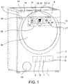
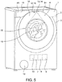
figures 1 - 5 are perspective views of a washing machine according to an embodiment of the invention, - -
figure 6 is a front view of a cooking oven according to an embodiment of the invention, - -
figures 7a, 7b, 7c, 7d are diagrammatic section views of a detail of the user interface of the household appliance according to embodiments, - -
figures 8a, 8b are section views of a detail of the housing of the household appliance at a display area according to embodiments, - -
figure 8c is a front view of a detail of the housing of the household appliance at a display area according to an embodiment, - -
figure 9 is a diagrammatic view of a washing machine according to an embodiment; - -
figure 10 is a diagrammatic view of a tumble dryer according to a further embodiment of the invention, - -
figure 11 is a diagrammatic view of a washing and drying machine according to a further embodiment of the invention; - -
figure 12 is a diagrammatic view of a dishwasher according to an embodiment; - -
figure 13 is a diagrammatic view of a domestic cooking oven according to an embodiment, - -
figure 14 is a diagrammatic view of the functional groups of a domestic microwave oven according to an embodiment. - -
figure 15 is a diagrammatic view of the functional groups of an electric or induction cook top according to an embodiment, - -
figure 16 is a diagrammatic view of the functional groups of a gas cook top according to an embodiment, - -
figure 17 is a diagrammatic view of the functional groups of a refrigerator according to an embodiment, - -
figure 18 is a diagrammatic view of the functional groups of a freezer according to an embodiment, - -
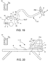
figure 19 is a diagrammatic view of the functional groups of a vacuum cleaner according to an embodiment, - -
figure 20 is a diagrammatic view of the functional groups of an ironing system according to an embodiment. - With reference to the figures, a
household appliance 1 comprises: - a
housing 2 with anouter wall 3 forming anouter surface 4 of thehousehold appliance 1, - a
treatment seat 5 adapted to receive and/or support domestic products in atreatment position 6, - at least one
treatment device 7 arranged inside thehousing 2 which can be operated to perform a treatment at thetreatment position 6 and subjecting the domestic product to said treatment, - at least one
treatment detector 8 arranged at least partially inside thehousing 2 and configured to detect a value of a treatment parameter of the treatment performed by thetreatment device 7, - optionally, at least one
anomaly detector 9 arranged at least partially inside thehousing 2 and configured to detect a value indicative of an operating anomaly of thehousehold appliance 1, - an
electronic control system 10 arranged in thehousing 2 and in signal connection with thetreatment device 7 and with thetreatment detector 8 and configured to command thetreatment device 7 in dependency of a treatment program and in dependency of the value detected by thetreatment detector 8, - a
user interface 11 in signal connection with theelectronic control system 10, saiduser interface 11 comprising:- command insertion means 12 for inputting commands (by a user) for selecting parameters of the treatment program and for inputting a command for executing the treatment program, and
- display means 13 which visualize the selectable parameters of the treatment program and/or visualize treatment parameters during the execution of the treatment program.
- According to an aspect of the invention, the display means 13 comprise at least one
video projector 14 mounted onto thehousehold appliance 1 at theouter wall 3 and configured to visualize, by means of a light projecting process onto adisplay area 15 of theouter surface 4 of thehousing 2. - According to a further aspect of the invention, the user command insertion means 12 comprise at least one
command input sensor 16 adapted to detect a positioning and/or a movement of the user's hand at thedisplay area 15, and generate a corresponding hand position and/or movement signal. Theelectronic control system 10 and/or theuser interface 19 comprises an interpretation and association module which receives and processes the hand position and/or movement signal and generates a user command signal in dependency of which theelectronic control system 10 sets the treatment program parameters and/or controls the display, by means of thevideo projector 14. - Detailed description of the
display area 15 of theouter surface 4 - According to an embodiment, in the areas of the
outer surface 4 provided to implement the visualization by projecting of light, theouter surface 4 is colored and treated so as to have a higher light reflectivity with respect to an area which is not intended for visualization. - According to a further embodiment, in the
display area 15, theouter surface 4 may be either continuous or discontinuous, e.g. formed by parts of theappliance 1 connected to one another without mutual continuity of the outer surface and/or moving parts. - According to an embodiment, in the areas of the
outer surface 4 intended for implementing the visualization by projecting light, theouter surface 4 may be planar or non-planar, e.g. curved. - According to an embodiment, the
household appliance 1 comprises adoor 18 for closing thetreatment seat 5 during the execution of the treatment program and thedisplay area 15 may extend at least also on the part of theouter surface 4 formed by thedoor 18. - According to an embodiment, the
treatment seat 5 is exposed directly to the outside of thehousehold appliance 1 and forms at least part of theouter surface 4, and thedisplay area 15 extends at least also on the part of theouter surface 4 formed by thetreatment seat 5. - According to an embodiment, the
housing 2 of theappliance 1 forms an auxiliary access opening for an accessory (e.g. a detergent drawer, a bag of powder, a filter, a condensation collection drawer) of the one ormore treatment devices 7, which can be closed by anauxiliary cover 19 during the execution of the treatment program, and thedisplay area 15 can extend at least also on the part of theouter surface 4 formed by theauxiliary cover 19. - According to an embodiment, the
household appliance 1 comprises asingle video projector 14. - According to a further embodiment, the
household appliance 1 comprises a plurality of saidvideo projectors 14 configured to project light onto onesame display area 15 and/or onto a plurality of saiddisplay areas 15 which are distinct and at a distance or adjacent to each other. - The
individual video projectors 14 may be positioned on two opposite or different sides of thedisplay area 15 and project in opposite directions or in different directions, in order to avoid the appearance of shadows when approaching of the user's hand to thedisplay area 15. - In the event of multiple light projections on the same display area, the
video projectors 14 are configured and controlled by theelectronic control system 10 so that the light wavelengths and/or the lighting frequency are compatible and do not imply destructive interferences of the projected light. - According to an embodiment, the
electronic control system 10 or thevideo projector 14 comprises anti-distortion means configured to calculate and generate a pre-counter-distorted image to be projected, e.g. by means of rectangle-to-trapezium pre-counter-distortion, in the opposite direction with respect to an inclined projection, e.g. from rectangle to trapezium, of the image projected onto theouter surface 4 because of the light cone of thevideo projector 14 and of the inclination of the projection axis with respect to theouter surface 4 in thedisplay area 15. - The pre-counter-distortion of the image occurs in dependency of the projection cone angle and of the inclination angle of the projection axis of the
video projector 14 with respect to theouter surface 4 in thedisplay area 15, so as to compensate the projection distortion. In this manner, it is possible, for example, to obtain a projected image with a rectangular or circular or oval contour, symmetrical with respect to two perpendicular symmetry axes. - According to embodiments, the one or
more video projectors 14 may comprise one or more of: - LCD video projector (liquid crystal display video projector)
- DLP video projector (micro-mirror video projector)
- LCoS video projector (Liquid Crystal on Silicon)
- D-ILA Video projector (Digital Direct Drive - Image Light Amplifier)
- SXRD video projector (Silicon X-tal Reflective Display)
- LP video projector (laser video projector), e.g. monochromatic,
- DLP video projector (Digital Light Processing)
- With particular advantage, in order not to interfere with the aesthetic design of the
housing 1, the one ormore video projectors 14 are configured as micro or pico projectors. - According to an embodiment, the
video projector 14 is positioned entirely inside thehousing 2 on aninner side 20 of theouter wall 3 and performs the light projection through a window opening 21 formed in theouter wall 3. The window opening 21 may be a through opening or protected by a protective wall 22 which is transparent and/or which can be opened and closed by means of a protective cover 23 and/or by means of a shutter 24. This allows to conceal and protect thevideo projector 14. - According to an embodiment, the
video projector 14 comprises aninner part 25 located entirely inside thehousing 2, i.e. on aninner side 20 of theouter wall 3, and anouter part 26 positioned completely outside thehousing 2, i.e. on an outer side of theouter wall 3, wherein the volume of theinner part 25 is greater than the volume of theouter part 26. This reduces the visual impact of the video projector on the aesthetic appearance of the household appliance. - According to an embodiment, the
video projector 14 is supported in a concealable and movable manner between a rest position inside thehousing 2 and a work position, in which thevideo projector 14 protrudes at least partially outside thehousing 2. - According to an embodiment, the position and/or orientation of the
video projector 14 are adjustable, e.g. by means of theelectronic control system 10. - Similarly, the position of the
display area 15, or in other words the position of the display, is adjustable, e.g. by means of theelectronic control system 10. - The
appliance 1 or the video projector may comprise a sharpness detector and/or a focal length detector, e.g. an optical sensor, and be configured for autofocus in dependency of a sharpness or focal length signal generated by the sharpness or focal length detector. - The
control system 10 may also be configured to visualize, by means of thevideo projector 14, alarms or warnings directly at a component (e.g.door 18,auxiliary door 19, detergent drawer, filter holder) to which the alarm or warning relates, preferably in response to anomaly signals supplied by theanomaly detector 9 or in response to command insertion signals 16 supplied by thecommand insertion sensor 16, wherein the component or quantity to detect/monitor falls within the scope of detection of such detectors/sensors - The warning or alarm visualization may comprise, for example, one or more of:
- a "component displaced" warning, e.g. door open if the
door - a "missing component or substance" or "insert component or substance" warning, e.g. "replace filter" if a filter is missing or needs to be replaced, or "filling detergent" if a level of the treatment substance is below a minimum level.
- According to a further embodiment, the
user interface 19 or thevideo projector 14 can comprise anaudio interface 51 controlled by theelectronic control system 10 to emit sound alerts (e.g. sounds, voice) in addition to the visualization operations of thevideo projector 14 and, possibly, so as to clarify acoustically the displayed information. - The features described with reference to a
video projector 14 apply to at least one, some or all of thevideo projectors 14 in the case of a plurality ofprojectors 14. - According to an embodiment, the
command insertion sensor 16 comprises a proximity or touch sensor, e.g. capacitive, applied to theouter wall 3 in thedisplay area 15. The touch sensor may comprise a film or a support panel on which an array of conductor(s) of the capacitors is formed, e.g. arranged according to Cartesian coordinates. - According to a further embodiment, the
command insertion sensor 16 comprise one or more radar interaction sensors arranged either at or near thedisplay area 15 and configured to recognize the position and movement of the user's hand in the immediate vicinity of thedisplay area 15, e.g. to recognize a plurality of movements of the index finger or of the index finger and thumb of the user's hand, e.g. the so-called slider dial motions, rotary dial motions, zoom motions and pan motions. - According to a further embodiment, the
command insertion sensor 16 comprises one or more optical interaction sensors arranged near thedisplay area 15 and configured to recognize the position and movement of the user's hand in the immediate vicinity of thedisplay area 15, e.g. to recognize a plurality of movements of the index finger or of the index finger and thumb of the user's hand, e.g. the so-called slider dial motions, rotary dial motions, zoom motions and pan motions. - The optical interaction sensor may comprise, for example, a video camera and an interpretation software for interpreting the images recorded by the camera.
- According to a further embodiment, the
command insertion sensors 16 comprise one or more infrared light sources and corresponding optical sensors configured to recognize the position and movement of the user's hand in the immediate vicinity of thedisplay area 15, e.g. to recognize a plurality of movements of the index finger or of the index finger and thumb of the user's hand, e.g. the so-called slider dial motions, rotary dial motions, zoom motions and pan motions. - According to an embodiment, the same
command insertion sensor 16 is further configured to monitor and/or verify the position and/or movements (e.g. vibrations) of moving or extractable parts (door 18,auxiliary cover 19, detergent drawer) which fall within its field or scope of detection. - According to a further embodiment, the command insertion means 12 may comprise an audio sensor or microphone adapted to detect audio user commands (in particular, voice commands) and to generate a corresponding voice signal. The electronic control system 10:
- processes the voice signal and generates a corresponding user command signal,
- sets the parameters of the treatment program in dependency of the generated user command signal,
- controls the display, by means of the
video projector 14, in dependency of the generated user command signal. - The features described with reference to a
command insertion sensor 16 apply to at least one, some or all of thecommand insertion sensors 16 in the case of a plurality of said command insertion sensors. - According to an embodiment, the interpretation and association module associates, e.g. by comparison of position, the detected position and/or the movement of the hand in one or more command input fields 17 visualized by means of the
video projector 14 in thedisplay area 15, and generates the user command signal in dependency of such association. - According to a further embodiment, the interpretation and association module interprets detected single positioning (touches) of the hand or finger associated with individual visualized command input fields 17 as parameter selection movements, e.g. from a plurality of different treatment parameters, and generates the user command signal in dependency of such interpretation.
- According to a further embodiment, the interpretation and association module interprets detected continual movement (sliding) of the hand or finger associated with individual visualized command input fields 17 as parameter value adjustment movements (slider dial motions) and generates the user command signal in dependency of such interpretation.
- According to a yet further embodiment, the interpretation and association module interprets detected continual and relative movements (relative sliding) of multiple detected fingers but not necessarily associated with given command input fields 17 as visualization adjustment and/or selection movements and generates the user command signal in dependency of such interpretation.
- Examples of movements and adjustment and/or visualization selection commands include zooming, panning, scrolling between multiple different screens, moving in the
entire display area 15, enlarging/reducing theentire display area 15. - According to an embodiment, the steps of interpreting the movements of the user's fingers may comprise steps of comparing characteristic parameters of the corresponding position and/or hand movement signals with reference parameters indicative of a plurality of predefined movements.
- According to a further embodiment, the steps of interpreting the movements of the user's fingers may comprise steps of calculating vector paths performed by the fingers.
- The
electronic control system 10 performs, by means of thevideo projector 14, a confirmation visualization of a user's command signal generated as a function of the aforesaid hand positioning and/or movement. - According to embodiments, confirmation visualization of the user's inputted command may comprise one or more of the following:
- a visualization, possibly highlighted, of an option or of a treatment program parameter to confirm the selection of the option or parameter,
- a variation of the treatment parameter selection menu,
- a visualization of a written alert, e.g. "start of treatment program" or "interruption of treatment program" or "household appliance off",
- a change in the display characteristics.
- According to an embodiment, in addition to the recognition of the position of the user's hand or finger on the
display area 15 and the association of the hand or finger position with a corresponding visualizedcommand input field 17, the one or moreinsertion command sensors 16 may also be configured to detect and recognize a plurality of movements of the index finger or of the index finger and thumb of the user's hand, e.g. the so-called slider dial motions, rotary or arc dial motions, as well as zoom in/out motions, video pan motions, the latter not necessarily specifically referred to a visualizedcommand input field 17, but corresponding to the gestures of the touchscreen controls known from the touchscreen tablet computers. - According to embodiments, the command input fields 17 may be visualized as images of one or more buttons, knobs, sliders, scales of values, or simple areas or fields, all possibly identified by a corresponding symbol, which represents e.g. a treatment parameter and/or one or more selectable values of a treatment parameter, and/or navigation command symbols for navigating between different command input menues, and/or edit or customization command symbols, such as zoom and/or brightness and/or language and/or shape of the
display area 15 and/or position/displacement of thedisplay area 15. - According to an embodiment, the
electronic control system 10 of thehousehold appliance 1 can be connected in a communication network, e.g. via Wi-Fi or using Bluetooth, with an externalelectronic device 52, e.g. a smart phone or tablet computer, and adapted to be controllable, e.g. configurable or upgradeable, by means of the externalelectronic device 52. - In this case, the
electronic control system 10 can be configured, by means of thevideo projector 14 and thecommand insertion sensor 16, to mirror a user interface with a control program present on theexternal device 52 or on a remote server and accessible by means of theexternal device 52. - According to embodiments, the
treatment devices 7 of thehousehold appliance 1 may comprise one or more of the following: - a hydraulic filling and emptying
system 27 and/or water circulation system to wet the domestic products in the treatment position, - a
ventilation system 28 and/or air circulation for aerating the domestic products in the treatment position, - a
heating system 29 for heating the domestic products and/or for heating the water of the hydraulic system and/or for heating the air in the ventilation system, - a
dehumidification system 30 for drying the household products and/or for dehumidifying the air ventilation system 28 (e.g. by means of condensation), - a
supply system 31 for delivering one or more chemical treatment substances directly on the domestic product and/or in the water in thehydraulic system 27 and/or in the air of theventilation system 28, - a
movement system 29a or mechanical agitation system to move the domestic product and/or thetreatment seat 5, e.g. with the purpose of dehydrating by centrifugal effect or varying exposure of the domestic product to thetreatment device 7 or agitation and mixing of the household product, - a
microwave generator 30a for generating microwaves in thetreatment position 6, - a
steam generator 31 a for generating steam in thetreatment position 6, - a generator (e.g. an induction coil) 32 of a variable electromagnetic field adapted to generate an induced electromotive force (and thus an induction heating) in electrically conductive pots in the
treatment position 6, - a
gas burner 33 adapted to heat pots or dishes in thetreatment position 6, - a
cooling system 34 and/or freezing system adapted to cool and/or freeze domestic products in thetreatment position 6. - According to embodiments, the
treatment detectors 8 may comprise one or more of the following: - a water pressure sensor 35,
- a
water level sensor 36, - a
water temperature sensor 37, - an
air pressure sensor 38, - a treatment
seat temperature sensor 39, - a
water turbidity sensor 40, - an
electric quantity sensor 41 of an electric motor of themovement system 29 and/or mechanical agitation system, - a
presence sensor 42 of domestic products in thetreatment position 6, - a
level sensor 43 or a presence sensor of a treatment chemical substance in the treatment substance delivery system, - a
position sensor 44 of movable parts of the appliance 1 (e.g.door 18,auxiliary door 19,detergent drawer 45,filter 46,filter holder 47, dust bag 48), - a
flame presence sensor 49, - a
camera 50 connected to or in thehousing 2 and directed towards thetreatment position 6 for monitoring the domestic product during the treatment. - According to an embodiment, the
video projector 14 may visualize images detected by thevideo camera 50. - According to embodiments, the
anomaly detectors 9 are also in signal connection with theelectronic control system 10 and may comprise one or more temperature sensors, water presence sensors, smoke presence sensors, water absence sensors, position/presence sensors of movable or detachable parts of the household appliance (e.g.door 18,auxiliary door 19,detergent drawer 45,filter 46, thefilter holder 47, dust bag 48). - According to embodiments, the
electronic control system 10 controls one ormore treatment devices 7 and/or controls the display means 13 also in dependency of the anomaly signals generated byanomaly detectors 9. - The
household appliance 1 is, for example, either: - a washing machine 1.1 (
figures 1-5 ,9 ,11 ), - a tumble dryer 1.2 (
figure 10 ), - a clothes washing and drying machine 1.3 (
figure 11 ), - a dishwasher 1.4 (
figure 12 ), - a domestic cooking oven 1.5 (
figure 13 ), - a microwave oven 1.6 (
figure 14 ), - a gas cook top 1.7 (
figure 16 ) and/or a resistive cook top 1.8 (figure 15 ), and/or an inductive cook top 1.9 (figure 15 ), - a refrigerator 1.10 (
figure 17 ), - a freezer 1.10 (
figure 18 ), - a vacuum cleaner 1.11 (
figure 19 ), - an ironing apparatus 1.12 (
figure 20 ). - According to embodiments, the household products which are treated by means of the
household appliance 1 may comprise one or more of either: - linen to be washed and/or dried and/or ironed,
- dishes to be washed,
- food products to be heated and/or cooked and/or defrosted and/or frozen and/or cooled,
- furniture surfaces to be dusted and/or washed,
- fabrics to be ironed or sewn.
- The washing machine 1.1 (
figure 1-5 ,9 ,11 ) comprises a laundry basket or drum which forms thetreatment seat 5 and which can be closed by means of adoor 18, as well as ahydraulic system 27, awater heating system 29, a dispensingsystem 31 and a movingsystem 29a. - The tumble dryer 1.2 (
figure 10 ) comprises a laundry basket or drum which forms thetreatment seat 5 and which can be closed by adoor 18, as well as aventilation system 28, anair heating system 29, adehumidification system 30 and an actuating/movingsystem 29a. - The washing and drying machine 1.3 (
figure 11 ) comprises a laundry basket or drum which forms thetreatment seat 5 and which can be closed by adoor 18, as well as ahydraulic system 27, awater heating system 29, a dispensingsystem 31,movement system 29a, aventilation system 28, anair heating system 29 and adehumidification system 30. - The dishwasher 1.4 (
figure 12 ) comprises a housing cavity which forms thetreatment seat 5 and which can be closed by adoor 18, as well as ahydraulic system 27, awater heating system 29, a dispensingsystem 31 and, optionally, adehumidification system 30. - The domestic cooking oven 1.5 (
figure 13 ) comprises a cooking cavity which forms thetreatment seat 5 and which can be closed by adoor 18, as well as aventilation system 28, aheating system 29 for heating the food products, optionally amovement system 29a (e.g. for turning grilled meat), optionally asteam generator 31a for generating steam in thetreatment position 6, optionally agas burner 33 adapted to heat dishes in thetreatment position 6. - The microwave oven 1.6 (
figure 14 ) comprises a cooking cavity which forms thetreatment seat 5 and which can be closed by adoor 18, as well as amicrowave generator 30a for generating microwaves in thetreatment position 6, amovement system 29a and optionally aventilation system 28. - The resistive cook top 1.8 (
figure 15 ) comprises a pot supporting structure which forms thetreatment seat 5, as well as aresistive heating system 29 for heating pots or dishes in thetreatment position 6. - The inductive cook top 1.9 (
figure 15 ) comprises a pot supporting structure which forms thetreatment seat 5, as well as a generator (e.g. induction coil) 32 of a variable electromagnetic field in thetreatment position 6. - The gas cook top 1.7 (
figure 16 ) comprises a pot supporting structure which forms thetreatment seat 5, as well as agas burner 33 adapted to heat pots or dishes in thetreatment position 6. - The refrigerator 1.10 (
figure 17 ) comprises a refrigeration cavity which forms thetreatment seat 5 and which can be closed by adoor 18, as well as acooling system 34 and/or freezing system adapted to cool and/or freeze domestic products in thetreatment position 6 and, optionally, aventilation system 28 and/or air circulation system for aerating the domestic products in thetreatment position 6. - The freezer 1.11 (
figure 18 ) comprises a freezing cavity which forms thetreatment seat 5 and which can be closed by adoor 18, as well as a freezingsystem 34 adapted to freeze the domestic products in thetreatment position 6. - The vacuum cleaner 1.12 (
figure 19 ) comprises a suction mouth for a furnishing surface which forms thetreatment seat 5, as well as aventilation system 28, in particular a suction system, of air from the furniture surface in thetreatment position 6 and, optionally, amovement system 29a or mechanical agitation system to move thetreatment seat 5. - The ironing apparatus 1.13 (
figure 20 ) comprises a heatable plate which forms thetreatment seat 5, as well as aheating system 29 for heating the heatable plate and asteam generator 31a for generating steam in thetreatment position 6. - Each of the
household appliances 1, 1.1 ... 1.12 described in greater detail may selectively comprise one ormore treatment detectors 8 and selectively one ormore anomaly detectors 9, together with their signal connections to theelectronic control system 10, described above and not repeated here for the sake of brevity. - Obviously, those skilled in art may make further changes and variations to the
household appliance 1 according to the present invention, all contained within the scope of protection of the invention as defined in the following claims, in order to meet contingent needs and specifications.
Claims (16)
- A household appliance (1) comprising:- a housing (2) with an outer wall (3) forming an outer surface (4) of the household appliance (1),- a treatment seat (5) formed in or on the housing (2) and suitable for receiving or supporting domestic products in a treatment position (6),- at least one treatment device (7) arranged inside the housing (2) and operable for performing a treatment at the treatment position (6) and subjecting the domestic product to said treatment,- at least one treatment detector (8) arranged at least partially inside the housing (2) and configured to detect a value of a treatment parameter of the treatment performed by the treatment device (7),- optionally, at least one anomaly detector (9) arranged at least partially inside the housing (2) and configured to detect a value indicative of an operating anomaly of the household appliance (1),- an electronic control system (10) arranged in the housing (2) and in signal connection with the treatment device (7) and with the treatment detector (8) and configured to command the treatment device (7) in dependency from a treatment program and in dependency from the value detected by the treatment detector (8),- a user interface (11) in signal connection with the electronic control system (10), said user interface (11) comprising:- command insertion means (12) for inserting commands for selecting parameters of the treatment program and for inserting a command for executing the treatment program, and- display means (13) which perform a visualization of the selectable parameters of the treatment program and a visualization of treatment parameters during the execution of the treatment program,characterized in that the display means (13) comprise at least one video projector (14) mounted onto the household appliance (1) at the outer wall (3) and configured to perform the visualization, by means of a process of light projecting onto a display area (15) of the outer surface (4) of the housing (2).
- A household appliance (1) according to any one of the preceding claims, comprising a plurality of said video projectors (14) configured to project light onto one same display area (15) and/or onto a plurality of said different display areas (15).
- A household appliance (1) according to any one of the preceding claims, comprising a plurality of said video projectors (14) positioned on opposite sides of the display area (15) and which project in different directions in the display area (15).
- A household appliance (1) according to any one of the preceding claims, comprising anti-distortion means configured to calculate and generate an image to be projected by the video projector (14) pre-counter-distorted in the opposite direction to a successive projection distortion due to the inclination of the central projection axis of the light cone of the video projector (14) with respect to the outer surface (4) in the display area (15), in order to compensate said projection distortion.
- A household appliance (1) according to any one of the preceding claims, wherein said video projector (14) is chosen from the group consisting of:- LCD video projector- DLP video projector- LCoS video projector- D-ILA video projector- SXRD video projector- Laser video projector- DLP video projector.
- A household appliance (1) according to any one of the preceding claims, wherein the video projector (14) is positioned entirely inside the housing (2) on an inner side (20) of the outer wall (3) and performs the light projection through a window opening (21) formed in the outer wall (3).
- A household appliance (1) according to claim 6, wherein the window opening (21) is protected by means of a transparent or openable and closable protective wall (22, 23, 24).
- A household appliance (1) according to any one of the preceding claims, wherein the video projector (14) comprises an inner part (25) positioned entirely inside the housing (2) and an outer part (26) positioned outside the housing (2), wherein the volume of the inner part (25) is greater than the volume of the outer part (26).
- A household appliance (1) according to any one of the preceding claims, wherein the video projector (14) is supported in a concealable manner and movable between a rest position inside the housing (2) and a work position, wherein the video projector (14) protrudes at least partially outside the housing (2).
- A household appliance (1) according to any one of the preceding claims, wherein the position of the video projector (14) with respect to the housing (1) is adjustable.
- A household appliance (1) according to any one of the preceding claims, wherein the position of the display area (15) is adjustable.
- A household appliance (1) according to any one of the preceding claims, comprising means for automatic focusing of the visualization.
- A household appliance (1) according to any one of the preceding claims, wherein the control system (10) implements a warning display, by means of the video projector (14), directly at a component (18, 19) of the household appliance (1) to which the warning refers, in dependency of anomaly signals supplied by the anomaly detector (9).
- A household appliance (1) according to any one of the preceding claims, wherein the user interface (19) comprises an audio interface (51) controlled by the electronic control system (10) for emitting vocal warnings, in addition to the video projector (14) display, and so as to vocally specify the displayed information.
- A household appliance (1) according to any one of the preceding claims, wherein, in the display area (15), the outer surface (4) is discontinuous or curved.
- A household appliance (1) according to any one of the preceding claims, comprising:- a door (18) for closing the treatment seat (5) during the execution of the treatment program, wherein the display area (15) extends at least also on the part of the outer surface (4) formed by the door (18), or- the treatment seat (5) is exposed directly to the outside of the household appliance (1) and forms at least one part of the outer surface (4), wherein the display area (15) extends at least also on the part of the outer surface (4) formed by the treatment seat (5), or- the housing (2) forms an auxiliary access opening for an accessory of the treatment device (7), said auxiliary access opening being closable by means of an auxiliary cover (19) and the display area (15) extends at least also on the part of the outer surface (4) formed by the auxiliary cover (19).
Applications Claiming Priority (1)
| Application Number | Priority Date | Filing Date | Title |
|---|---|---|---|
| IT102018000003722A IT201800003722A1 (en) | 2018-03-19 | 2018-03-19 | APPLIANCE WITH USER INTERFACE |
Publications (2)
| Publication Number | Publication Date |
|---|---|
| EP3543990A1 true EP3543990A1 (en) | 2019-09-25 |
| EP3543990B1 EP3543990B1 (en) | 2025-08-06 |
Family
ID=62530447
Family Applications (1)
| Application Number | Title | Priority Date | Filing Date |
|---|---|---|---|
| EP19163750.3A Active EP3543990B1 (en) | 2018-03-19 | 2019-03-19 | Household appliance with user interface |
Country Status (3)
| Country | Link |
|---|---|
| EP (1) | EP3543990B1 (en) |
| CN (1) | CN110286747B (en) |
| IT (1) | IT201800003722A1 (en) |
Cited By (5)
| Publication number | Priority date | Publication date | Assignee | Title |
|---|---|---|---|---|
| KR20210054796A (en) * | 2019-11-06 | 2021-05-14 | 엘지전자 주식회사 | Door open monitoring for the intelligent device |
| EP3842586A1 (en) * | 2019-12-25 | 2021-06-30 | Arçelik Anonim Sirketi | A washing machine comprising a filter |
| CN114232285A (en) * | 2021-12-08 | 2022-03-25 | 珠海格力电器股份有限公司 | Washing machine projection and cleaning device and control method thereof |
| CN114657743A (en) * | 2020-12-23 | 2022-06-24 | 青岛海高设计制造有限公司 | Method and device for controlling washing equipment to open door and washing equipment |
| EP4124934A1 (en) * | 2021-07-30 | 2023-02-01 | Miele & Cie. KG | Method for driving a device, household appliance, method for operating a device and device |
Families Citing this family (3)
| Publication number | Priority date | Publication date | Assignee | Title |
|---|---|---|---|---|
| CN111088662B (en) * | 2019-12-19 | 2021-02-26 | 珠海格力电器股份有限公司 | Operation panel and washing machine with same |
| CN112596662A (en) * | 2020-12-25 | 2021-04-02 | 珠海格力电器股份有限公司 | Non-direct contact display operation system and clothes treatment device thereof |
| CN117760139A (en) * | 2022-09-16 | 2024-03-26 | 海信容声(广东)冰箱有限公司 | An ice maker and refrigerator with a mold cavity formed by clamping the mold |
Citations (8)
| Publication number | Priority date | Publication date | Assignee | Title |
|---|---|---|---|---|
| DE10237316A1 (en) * | 2002-08-15 | 2004-02-26 | Segerer, Jürgen | Technical product, e.g. a household appliance, presentation arrangement, in which a computer controlled projection screen is integrated within the appliance so that appliance operation can be simulated |
| DE102004036212A1 (en) * | 2004-07-26 | 2006-03-30 | BSH Bosch und Siemens Hausgeräte GmbH | Household appliance device for e.g. baking oven, has display unit with projection unit provided for projecting light at indicator unit of display unit into household appliance door, where projection unit has light deflecting unit |
| EP1814003A1 (en) * | 2006-01-31 | 2007-08-01 | Liebherr-Hausgeräte Ochsenhausen GmbH | Household appliance with projection device |
| US20120327201A1 (en) * | 2011-06-27 | 2012-12-27 | General Electric Company | Projected user interface onto the surface of an appliance |
| DE102012103684A1 (en) * | 2012-04-26 | 2013-10-31 | Miele & Cie. Kg | Display device i.e. projector, for use in oven, has optic causing deflection for light beams, and comprising light guide elements that influence projection of projection image into review region formed in window |
| EP2988647A1 (en) * | 2013-04-23 | 2016-03-02 | BSH Hausgeräte GmbH | Dishwasher machine comprising at least one optical display associated with a functional component |
| US20160191877A1 (en) * | 2014-12-25 | 2016-06-30 | Panasonic Intellectual Property Management Co., Ltd. | Projector device and projection method |
| EP3124688A1 (en) * | 2015-07-27 | 2017-02-01 | Electrolux Appliances Aktiebolag | A laundry dryer |
Family Cites Families (9)
| Publication number | Priority date | Publication date | Assignee | Title |
|---|---|---|---|---|
| JP3963248B2 (en) * | 2000-06-29 | 2007-08-22 | 株式会社日立製作所 | Household electrical equipment |
| EP1862581B2 (en) * | 2006-06-01 | 2020-09-09 | Electrolux Home Products Corporation N.V. | Method for operating a domestic appliance, especially a home dryer or a washing machine, and domestic appliance |
| JP2009279082A (en) * | 2008-05-20 | 2009-12-03 | Hitachi Appliances Inc | Washing machine and washing drying machine |
| JP2011250848A (en) * | 2010-05-31 | 2011-12-15 | Sharp Corp | Washing machine |
| US9116567B2 (en) * | 2012-04-25 | 2015-08-25 | Google Technology Holdings LLC | Systems and methods for managing the display of content on an electronic device |
| SE537730C2 (en) * | 2012-05-14 | 2015-10-06 | Scania Cv Ab | Projected virtual vehicle entry system |
| WO2017122256A1 (en) * | 2016-01-14 | 2017-07-20 | パナソニックIpマネジメント株式会社 | Washing machine |
| CN107315509B (en) * | 2017-06-05 | 2023-09-15 | 青岛胶南海尔洗衣机有限公司 | A non-contact control device, signal processing method and household appliances thereof |
| CN107545569A (en) * | 2017-08-23 | 2018-01-05 | 北京小米移动软件有限公司 | Method for recognizing impurities and device |
-
2018
- 2018-03-19 IT IT102018000003722A patent/IT201800003722A1/en unknown
-
2019
- 2019-03-19 CN CN201910209326.8A patent/CN110286747B/en active Active
- 2019-03-19 EP EP19163750.3A patent/EP3543990B1/en active Active
Patent Citations (8)
| Publication number | Priority date | Publication date | Assignee | Title |
|---|---|---|---|---|
| DE10237316A1 (en) * | 2002-08-15 | 2004-02-26 | Segerer, Jürgen | Technical product, e.g. a household appliance, presentation arrangement, in which a computer controlled projection screen is integrated within the appliance so that appliance operation can be simulated |
| DE102004036212A1 (en) * | 2004-07-26 | 2006-03-30 | BSH Bosch und Siemens Hausgeräte GmbH | Household appliance device for e.g. baking oven, has display unit with projection unit provided for projecting light at indicator unit of display unit into household appliance door, where projection unit has light deflecting unit |
| EP1814003A1 (en) * | 2006-01-31 | 2007-08-01 | Liebherr-Hausgeräte Ochsenhausen GmbH | Household appliance with projection device |
| US20120327201A1 (en) * | 2011-06-27 | 2012-12-27 | General Electric Company | Projected user interface onto the surface of an appliance |
| DE102012103684A1 (en) * | 2012-04-26 | 2013-10-31 | Miele & Cie. Kg | Display device i.e. projector, for use in oven, has optic causing deflection for light beams, and comprising light guide elements that influence projection of projection image into review region formed in window |
| EP2988647A1 (en) * | 2013-04-23 | 2016-03-02 | BSH Hausgeräte GmbH | Dishwasher machine comprising at least one optical display associated with a functional component |
| US20160191877A1 (en) * | 2014-12-25 | 2016-06-30 | Panasonic Intellectual Property Management Co., Ltd. | Projector device and projection method |
| EP3124688A1 (en) * | 2015-07-27 | 2017-02-01 | Electrolux Appliances Aktiebolag | A laundry dryer |
Cited By (6)
| Publication number | Priority date | Publication date | Assignee | Title |
|---|---|---|---|---|
| KR20210054796A (en) * | 2019-11-06 | 2021-05-14 | 엘지전자 주식회사 | Door open monitoring for the intelligent device |
| EP3842586A1 (en) * | 2019-12-25 | 2021-06-30 | Arçelik Anonim Sirketi | A washing machine comprising a filter |
| CN114657743A (en) * | 2020-12-23 | 2022-06-24 | 青岛海高设计制造有限公司 | Method and device for controlling washing equipment to open door and washing equipment |
| EP4124934A1 (en) * | 2021-07-30 | 2023-02-01 | Miele & Cie. KG | Method for driving a device, household appliance, method for operating a device and device |
| BE1029635B1 (en) * | 2021-07-30 | 2023-02-28 | Miele & Cie | Method for controlling a device, household appliance, method for operating a device and device |
| CN114232285A (en) * | 2021-12-08 | 2022-03-25 | 珠海格力电器股份有限公司 | Washing machine projection and cleaning device and control method thereof |
Also Published As
| Publication number | Publication date |
|---|---|
| CN110286747A (en) | 2019-09-27 |
| EP3543990B1 (en) | 2025-08-06 |
| RU2019107675A (en) | 2020-09-18 |
| CN110286747B (en) | 2023-11-28 |
| RU2019107671A (en) | 2020-09-18 |
| IT201800003722A1 (en) | 2019-09-19 |
Similar Documents
| Publication | Publication Date | Title |
|---|---|---|
| EP3543990B1 (en) | Household appliance with user interface | |
| EP3543390B1 (en) | Household appliance with user interface | |
| US10222964B2 (en) | Operation device and operation method | |
| CN108475177B (en) | Drag set user interface for appliances | |
| US9709283B2 (en) | User interface for white goods and associated multi-channel proximity sensors | |
| EP2444734A2 (en) | Cooker and control method thereof | |
| US11782677B2 (en) | User-interface system for a laundry appliance | |
| US20120327201A1 (en) | Projected user interface onto the surface of an appliance | |
| CN109963975B (en) | Household appliance with projection device and operation method thereof | |
| EP3128240B1 (en) | Household appliance system and household appliance | |
| EP2979036A2 (en) | User interface for white goods and associated multi-channel proximity sensors | |
| CN115190956A (en) | Setting target browning level on household cooking appliance | |
| EP2259169B1 (en) | Houshold appliance with virtual data interface | |
| CN105829803A (en) | Heating cooker | |
| RU2787682C2 (en) | Electrical household appliance with user interface | |
| RU2787761C2 (en) | Household electrical appliance with user interface | |
| JP2019124441A (en) | Cooker | |
| KR20130136890A (en) | Microwave oven and method for controlling input the same | |
| US20250179711A1 (en) | System and method for remote monitoring and control of household appliances | |
| CN211857239U (en) | Household appliance | |
| CN121048173A (en) | Cooking equipment, methods for providing user interfaces, and home appliances | |
| KR20250049165A (en) | Cooking apparatus and method of controlling cooking apparatus | |
| TR201921442A1 (en) | A TOUCH PROJECTION AND WORKING METHOD USED IN BUILT-IN SETS | |
| BR112018014111B1 (en) | DRAG-AND-SET USER INTERFACE APPLICATION |
Legal Events
| Date | Code | Title | Description |
|---|---|---|---|
| PUAI | Public reference made under article 153(3) epc to a published international application that has entered the european phase |
Free format text: ORIGINAL CODE: 0009012 |
|
| STAA | Information on the status of an ep patent application or granted ep patent |
Free format text: STATUS: THE APPLICATION HAS BEEN PUBLISHED |
|
| AK | Designated contracting states |
Kind code of ref document: A1 Designated state(s): AL AT BE BG CH CY CZ DE DK EE ES FI FR GB GR HR HU IE IS IT LI LT LU LV MC MK MT NL NO PL PT RO RS SE SI SK SM TR |
|
| AX | Request for extension of the european patent |
Extension state: BA ME |
|
| STAA | Information on the status of an ep patent application or granted ep patent |
Free format text: STATUS: REQUEST FOR EXAMINATION WAS MADE |
|
| 17P | Request for examination filed |
Effective date: 20200102 |
|
| RBV | Designated contracting states (corrected) |
Designated state(s): AL AT BE BG CH CY CZ DE DK EE ES FI FR GB GR HR HU IE IS IT LI LT LU LV MC MK MT NL NO PL PT RO RS SE SI SK SM TR |
|
| STAA | Information on the status of an ep patent application or granted ep patent |
Free format text: STATUS: EXAMINATION IS IN PROGRESS |
|
| 17Q | First examination report despatched |
Effective date: 20220311 |
|
| RAP3 | Party data changed (applicant data changed or rights of an application transferred) |
Owner name: CANDY S.P.A. |
|
| RIN1 | Information on inventor provided before grant (corrected) |
Inventor name: FUMAGALLI, ALDO |
|
| GRAP | Despatch of communication of intention to grant a patent |
Free format text: ORIGINAL CODE: EPIDOSNIGR1 |
|
| STAA | Information on the status of an ep patent application or granted ep patent |
Free format text: STATUS: GRANT OF PATENT IS INTENDED |
|
| RIC1 | Information provided on ipc code assigned before grant |
Ipc: D06F 105/60 20200101ALN20250221BHEP Ipc: D06F 105/58 20200101ALN20250221BHEP Ipc: D06F 103/00 20200101ALN20250221BHEP Ipc: D06F 39/14 20060101ALN20250221BHEP Ipc: D06F 37/42 20060101ALN20250221BHEP Ipc: G09F 23/00 20060101ALI20250221BHEP Ipc: F25D 29/00 20060101ALI20250221BHEP Ipc: F24C 7/08 20060101ALI20250221BHEP Ipc: D06F 34/32 20200101ALI20250221BHEP Ipc: A47L 15/42 20060101ALI20250221BHEP Ipc: G09F 19/18 20060101AFI20250221BHEP |
|
| INTG | Intention to grant announced |
Effective date: 20250312 |
|
| RIN1 | Information on inventor provided before grant (corrected) |
Inventor name: FUMAGALLI, ALDO |
|
| GRAS | Grant fee paid |
Free format text: ORIGINAL CODE: EPIDOSNIGR3 |
|
| GRAA | (expected) grant |
Free format text: ORIGINAL CODE: 0009210 |
|
| STAA | Information on the status of an ep patent application or granted ep patent |
Free format text: STATUS: THE PATENT HAS BEEN GRANTED |
|
| AK | Designated contracting states |
Kind code of ref document: B1 Designated state(s): AL AT BE BG CH CY CZ DE DK EE ES FI FR GB GR HR HU IE IS IT LI LT LU LV MC MK MT NL NO PL PT RO RS SE SI SK SM TR |
|
| REG | Reference to a national code |
Ref country code: GB Ref legal event code: FG4D |
|
| REG | Reference to a national code |
Ref country code: CH Ref legal event code: EP |
|
| REG | Reference to a national code |
Ref country code: DE Ref legal event code: R096 Ref document number: 602019073567 Country of ref document: DE |
|
| REG | Reference to a national code |
Ref country code: IE Ref legal event code: FG4D |
|
| REG | Reference to a national code |
Ref country code: NL Ref legal event code: MP Effective date: 20250806 |
|
| PG25 | Lapsed in a contracting state [announced via postgrant information from national office to epo] |
Ref country code: IS Free format text: LAPSE BECAUSE OF FAILURE TO SUBMIT A TRANSLATION OF THE DESCRIPTION OR TO PAY THE FEE WITHIN THE PRESCRIBED TIME-LIMIT Effective date: 20251206 |
|
| PG25 | Lapsed in a contracting state [announced via postgrant information from national office to epo] |
Ref country code: NO Free format text: LAPSE BECAUSE OF FAILURE TO SUBMIT A TRANSLATION OF THE DESCRIPTION OR TO PAY THE FEE WITHIN THE PRESCRIBED TIME-LIMIT Effective date: 20251106 |
|
| REG | Reference to a national code |
Ref country code: LT Ref legal event code: MG9D |
|
| PG25 | Lapsed in a contracting state [announced via postgrant information from national office to epo] |
Ref country code: PT Free format text: LAPSE BECAUSE OF FAILURE TO SUBMIT A TRANSLATION OF THE DESCRIPTION OR TO PAY THE FEE WITHIN THE PRESCRIBED TIME-LIMIT Effective date: 20251209 |
|
| PG25 | Lapsed in a contracting state [announced via postgrant information from national office to epo] |
Ref country code: FI Free format text: LAPSE BECAUSE OF FAILURE TO SUBMIT A TRANSLATION OF THE DESCRIPTION OR TO PAY THE FEE WITHIN THE PRESCRIBED TIME-LIMIT Effective date: 20250806 |
|
| PG25 | Lapsed in a contracting state [announced via postgrant information from national office to epo] |
Ref country code: NL Free format text: LAPSE BECAUSE OF FAILURE TO SUBMIT A TRANSLATION OF THE DESCRIPTION OR TO PAY THE FEE WITHIN THE PRESCRIBED TIME-LIMIT Effective date: 20250806 Ref country code: HR Free format text: LAPSE BECAUSE OF FAILURE TO SUBMIT A TRANSLATION OF THE DESCRIPTION OR TO PAY THE FEE WITHIN THE PRESCRIBED TIME-LIMIT Effective date: 20250806 |
|
| PG25 | Lapsed in a contracting state [announced via postgrant information from national office to epo] |
Ref country code: GR Free format text: LAPSE BECAUSE OF FAILURE TO SUBMIT A TRANSLATION OF THE DESCRIPTION OR TO PAY THE FEE WITHIN THE PRESCRIBED TIME-LIMIT Effective date: 20251107 |
|
| PG25 | Lapsed in a contracting state [announced via postgrant information from national office to epo] |
Ref country code: SE Free format text: LAPSE BECAUSE OF FAILURE TO SUBMIT A TRANSLATION OF THE DESCRIPTION OR TO PAY THE FEE WITHIN THE PRESCRIBED TIME-LIMIT Effective date: 20250806 |
|
| PG25 | Lapsed in a contracting state [announced via postgrant information from national office to epo] |
Ref country code: LV Free format text: LAPSE BECAUSE OF FAILURE TO SUBMIT A TRANSLATION OF THE DESCRIPTION OR TO PAY THE FEE WITHIN THE PRESCRIBED TIME-LIMIT Effective date: 20250806 |
|
| PG25 | Lapsed in a contracting state [announced via postgrant information from national office to epo] |
Ref country code: PL Free format text: LAPSE BECAUSE OF FAILURE TO SUBMIT A TRANSLATION OF THE DESCRIPTION OR TO PAY THE FEE WITHIN THE PRESCRIBED TIME-LIMIT Effective date: 20250806 Ref country code: BG Free format text: LAPSE BECAUSE OF FAILURE TO SUBMIT A TRANSLATION OF THE DESCRIPTION OR TO PAY THE FEE WITHIN THE PRESCRIBED TIME-LIMIT Effective date: 20250806 |
|
| PG25 | Lapsed in a contracting state [announced via postgrant information from national office to epo] |
Ref country code: RS Free format text: LAPSE BECAUSE OF FAILURE TO SUBMIT A TRANSLATION OF THE DESCRIPTION OR TO PAY THE FEE WITHIN THE PRESCRIBED TIME-LIMIT Effective date: 20251106 |
|
| PG25 | Lapsed in a contracting state [announced via postgrant information from national office to epo] |
Ref country code: ES Free format text: LAPSE BECAUSE OF FAILURE TO SUBMIT A TRANSLATION OF THE DESCRIPTION OR TO PAY THE FEE WITHIN THE PRESCRIBED TIME-LIMIT Effective date: 20250806 |
|
| REG | Reference to a national code |
Ref country code: AT Ref legal event code: MK05 Ref document number: 1822896 Country of ref document: AT Kind code of ref document: T Effective date: 20250806 |
|
| PG25 | Lapsed in a contracting state [announced via postgrant information from national office to epo] |
Ref country code: SM Free format text: LAPSE BECAUSE OF FAILURE TO SUBMIT A TRANSLATION OF THE DESCRIPTION OR TO PAY THE FEE WITHIN THE PRESCRIBED TIME-LIMIT Effective date: 20250806 |
|
| PG25 | Lapsed in a contracting state [announced via postgrant information from national office to epo] |
Ref country code: DK Free format text: LAPSE BECAUSE OF FAILURE TO SUBMIT A TRANSLATION OF THE DESCRIPTION OR TO PAY THE FEE WITHIN THE PRESCRIBED TIME-LIMIT Effective date: 20250806 |
|
| PG25 | Lapsed in a contracting state [announced via postgrant information from national office to epo] |
Ref country code: AT Free format text: LAPSE BECAUSE OF FAILURE TO SUBMIT A TRANSLATION OF THE DESCRIPTION OR TO PAY THE FEE WITHIN THE PRESCRIBED TIME-LIMIT Effective date: 20250806 |
|
| PGFP | Annual fee paid to national office [announced via postgrant information from national office to epo] |
Ref country code: IT Payment date: 20260223 Year of fee payment: 8 |
|
| PG25 | Lapsed in a contracting state [announced via postgrant information from national office to epo] |
Ref country code: CZ Free format text: LAPSE BECAUSE OF FAILURE TO SUBMIT A TRANSLATION OF THE DESCRIPTION OR TO PAY THE FEE WITHIN THE PRESCRIBED TIME-LIMIT Effective date: 20250806 |
|
| PG25 | Lapsed in a contracting state [announced via postgrant information from national office to epo] |
Ref country code: EE Free format text: LAPSE BECAUSE OF FAILURE TO SUBMIT A TRANSLATION OF THE DESCRIPTION OR TO PAY THE FEE WITHIN THE PRESCRIBED TIME-LIMIT Effective date: 20250806 Ref country code: SK Free format text: LAPSE BECAUSE OF FAILURE TO SUBMIT A TRANSLATION OF THE DESCRIPTION OR TO PAY THE FEE WITHIN THE PRESCRIBED TIME-LIMIT Effective date: 20250806 |