EP3543864B1 - Electronic control device - Google Patents
Electronic control device Download PDFInfo
- Publication number
- EP3543864B1 EP3543864B1 EP17870904.4A EP17870904A EP3543864B1 EP 3543864 B1 EP3543864 B1 EP 3543864B1 EP 17870904 A EP17870904 A EP 17870904A EP 3543864 B1 EP3543864 B1 EP 3543864B1
- Authority
- EP
- European Patent Office
- Prior art keywords
- travel plan
- reconfiguration
- calculation units
- unit
- evaluation
- Prior art date
- Legal status (The legal status is an assumption and is not a legal conclusion. Google has not performed a legal analysis and makes no representation as to the accuracy of the status listed.)
- Active
Links
Images




Classifications
-
- G—PHYSICS
- G01—MEASURING; TESTING
- G01C—MEASURING DISTANCES, LEVELS OR BEARINGS; SURVEYING; NAVIGATION; GYROSCOPIC INSTRUMENTS; PHOTOGRAMMETRY OR VIDEOGRAMMETRY
- G01C21/00—Navigation; Navigational instruments not provided for in groups G01C1/00 - G01C19/00
- G01C21/26—Navigation; Navigational instruments not provided for in groups G01C1/00 - G01C19/00 specially adapted for navigation in a road network
- G01C21/34—Route searching; Route guidance
- G01C21/3407—Route searching; Route guidance specially adapted for specific applications
- G01C21/3415—Dynamic re-routing, e.g. recalculating the route when the user deviates from calculated route or after detecting real-time traffic data or accidents
-
- G—PHYSICS
- G08—SIGNALLING
- G08G—TRAFFIC CONTROL SYSTEMS
- G08G1/00—Traffic control systems for road vehicles
- G08G1/16—Anti-collision systems
- G08G1/165—Anti-collision systems for passive traffic, e.g. including static obstacles, trees
-
- B—PERFORMING OPERATIONS; TRANSPORTING
- B60—VEHICLES IN GENERAL
- B60W—CONJOINT CONTROL OF VEHICLE SUB-UNITS OF DIFFERENT TYPE OR DIFFERENT FUNCTION; CONTROL SYSTEMS SPECIALLY ADAPTED FOR HYBRID VEHICLES; ROAD VEHICLE DRIVE CONTROL SYSTEMS FOR PURPOSES NOT RELATED TO THE CONTROL OF A PARTICULAR SUB-UNIT
- B60W60/00—Drive control systems specially adapted for autonomous road vehicles
- B60W60/001—Planning or execution of driving tasks
-
- G—PHYSICS
- G01—MEASURING; TESTING
- G01C—MEASURING DISTANCES, LEVELS OR BEARINGS; SURVEYING; NAVIGATION; GYROSCOPIC INSTRUMENTS; PHOTOGRAMMETRY OR VIDEOGRAMMETRY
- G01C21/00—Navigation; Navigational instruments not provided for in groups G01C1/00 - G01C19/00
- G01C21/26—Navigation; Navigational instruments not provided for in groups G01C1/00 - G01C19/00 specially adapted for navigation in a road network
- G01C21/34—Route searching; Route guidance
- G01C21/3446—Details of route searching algorithms, e.g. Dijkstra, A*, arc-flags or using precalculated routes
Definitions
- the present invention relates to an electronic control device.
- An electronic control device for autonomously driving a vehicle performs a process of calculating a travel plan for traveling in an optimal path and at an optimal speed to a destination in addition to a process of perceiving a road sign or an obstacle.
- a large amount of calculation is required, and a calculation unit with a large calculation capacity is required to achieve the large amount of calculation.
- the dynamic reconfiguration is a technique for changing a calculation circuit configuration in a reconfigurable circuit being operated. Using this dynamic reconfiguration, the calculation circuit is changed depending on the situation, and even a small-scale reconfigurable circuit can have a large calculation capacity.
- PTL 1 is disclosed as a background art in this technical field.
- a control unit 13 controls a dynamic reconfiguration control unit 16 on the basis of information from a sensor 18 in a vehicle to reconfigure a circuit of image processing hardware 11, thereby always enabling image processing depending on a driving environment.
- the control unit 13 controls an external device 19, such as a headlight or a brake, on the basis of information to which image processing is performed as described above.
- the dynamic reconfiguration is performed to change the configuration of an image processing circuit in a reconfigurable circuit and processing parameters depending on a driving state.
- the circuit is configured not to perform calculation during the dynamic reconfiguration, and alternative processing, such as stopping an output therefrom or directly outputting a previous calculated value, is required.
- alternative processing such as stopping an output therefrom or directly outputting a previous calculated value.
- An object of the present invention is to achieve an electronic control device capable of calculating an optimal travel plan even during dynamic reconfiguration of a calculation circuit configuration.
- the present invention is configured as follows.
- an electronic control device capable of calculating an optimal travel plan even during dynamic reconfiguration of a calculation circuit configuration can be achieved.
- FIG. 1 is a diagram illustrating a configuration example of the electronic control device and peripheral circuits according to the present invention.
- the electronic control device 1 calculates a travel plan to a destination by using contents set by an autonomous drive setting unit 2, sensor values output from a plurality of sensors 3, information output from a communication device 4, host vehicle position information output from a vehicle position information acquisition unit 5, and map information stored in a map information storage unit 6.
- the electronic control device 1 outputs a control instruction value for achieving the calculated travel plan to a plurality of vehicle control devices 7.
- vehicle control devices 7 includes, for example, an engine, a transmission, a brake, a steering device, and an electronic control device for controlling the engine, transmission, brake, and the steering device.
- the autonomous drive setting unit 2 is a device for an occupant of the vehicle to set a destination, a route, traveling speed, and the like during autonomous driving.
- the autonomous drive setting unit 2 includes an input device (not illustrated) for the occupant to perform setting.
- the input device includes, for example, a physical input device, such as a button or a touch panel, a gesture input device using a camera or infrared sensor, or a voice input device.
- the autonomous drive setting unit 2 outputs the information input by the occupant to the electronic control device 1 via the input device.
- Each of the sensor 3 is a sensor for acquiring external information or vehicle state information, and includes, for example, a camera, a radar, an ultrasonic sensor, an acceleration sensor, a yaw rate sensor, or a wheel speed sensor.
- the sensor 3 outputs, as the sensor value, the acquired information to the electronic control device 1.
- the communication device 4 communicates with the outside of the vehicle, for example, another vehicle or an infrastructure system and outputs information from outside the vehicle to the electronic control device 1.
- the vehicle position information acquisition unit 5 is a device for acquiring the position of a host vehicle by using a radio wave from a navigation satellite, such as a global positioning system (GPS).
- the vehicle position information acquisition unit 5 outputs acquired host vehicle position information to the electronic control device 1.
- GPS global positioning system
- the vehicle position information acquisition unit 5 may acquire the host vehicle position information by using a positioning system other than the GPS.
- the map information stored in the map information storage unit 6 is map data used for autonomous driving and includes, for example, a road width, the number of lanes, gradient, the curvature of a curve, the shape of an intersection, and speed limit information.
- the map information is stored outside the electronic control device 1 but may be stored inside the electronic control device 1.
- the electronic control device 1 internally includes a reconfigurable circuit 10, a controller 20, and a memory 40.
- the reconfigurable circuit 10 is a circuit having an internal circuit, the configuration of which is changeable, and includes, for example, a filed programmable gate array (FPGA) or a complex programmable logic device (CPLD).
- FPGA filed programmable gate array
- CPLD complex programmable logic device
- the reconfigurable circuit 10 internally includes a surrounding situation perception unit 11, a risk map generation unit 12, a travel plan evaluation unit 13, and a reconfiguration control unit 16.
- the surrounding situation perception unit 11 perceives situations around the host vehicle, for example, the contents of road signs, traffic signal situations, other vehicles around the host vehicle, and pedestrian situations.
- the surrounding situation perception unit 11 outputs peripheral perception information to the risk map generation unit 12.
- the risk map generation unit 12 generates a risk map 41 used for travel plan evaluation by using the host vehicle position information output from the vehicle position information acquisition unit 5, the map information stored in the map information storage unit 6, and the peripheral perception information output from the surrounding situation perception unit 11. Details of the risk map 41 will be described later with reference to FIG. 3 .
- the risk map generation unit 12 stores the generated risk map 41 in the memory 40.
- the processing of the surrounding situation perception unit 11 and the risk map generation unit 12 is performed in the reconfigurable circuit 10, but the processing may be performed in the controller 20. Furthermore, the processing may be performed by another processing device inside the electronic control device 1 or a processing device outside the electronic control device 1.
- the travel plan evaluation unit 13 includes a plurality of independent evaluation calculation units 141 to 14N.
- the number of the evaluation calculation units 141 to 14N is set to N.
- each of the evaluation calculation units 141 to 14N includes a vehicle model (not illustrated) and a risk map holding area 15 therein.
- the risk map 41 used for the travel plan evaluation is partially stored.
- the evaluation calculation units 141 to 14N use the host vehicle position information output from the vehicle position information acquisition unit 5, the travel plan parameters 251 to 25N output from the controller 20, and the vehicle model in the evaluation calculation unit to calculate the traveling trajectory, traveling speed, and the like of the vehicle. Thereafter, the evaluation calculation units 141 to 14N evaluates the travel plan parameters 251 to 25N by using the calculated traveling trajectory and traveling speed of the vehicle, target point information 23 output from the controller 20, risk map information stored in the risk map holding areas, and outputs evaluation results 261 to 26N to the controller 20. Details of the contents of this evaluation will be described later.
- Each of the evaluation calculation units 141 to 14N includes the risk map holding area 15.
- the number of the risk map holding areas 15 for the evaluation calculation units does not necessarily correspond one-to-one with the number of the evaluation calculation units 141 to 14N, and a risk map holding area 15 may be shared between the plurality of evaluation calculation units 141 to 14N. However, a plurality of the risk map holding areas 15 are required.
- the reconfiguration control unit 16 reconfigures the evaluation calculation units 141 to 14N.
- the reconfiguration control unit 16 selects data matching reconfiguration circuit data information 29 from among circuit data 421 to 42X stored in the memory 40, and reads the data, as circuit data 43, from the memory 40.
- the reconfiguration control unit 16 reconfigures evaluation calculation units of the evaluation calculation units 141 to 14N corresponding to information 28 about calculation units to be reconfigured.
- the reconfiguration control unit 16 outputs a reconfiguration completion signal 30 to the controller 20.
- the controller 20 internally includes a driving state control unit 21, a travel plan parameter generation/selection unit 24, and a parameter conversion unit 32.
- the driving state control unit 21 determines a current driving state on the basis of autonomous driving setting information output from the autonomous drive setting unit 2, the host vehicle position information output from the vehicle position information acquisition unit 5, and the map information, and determines a target point in the travel plan.
- the determined driving state 22 (signal indicating the driving state) is output to the path parameter generation/selection unit 24, and a target point 23 determined is output to the travel plan evaluation unit 13.
- the driving state 22 includes, for example, a straight traveling state, a right-hand curve state, a left-hand curve state, a right turning state, a left turning state, and a preceding vehicle following state. Furthermore, the invention as claimed employs a method of calculating a travel plan for each of sections obtained by partitioning a route to a destination which is set by the autonomous drive setting unit 2 into several sections, and the above-described target point 23 represents a target coordinate position in each section.
- the processing of the driving state control unit 21 is performed by the controller 20, but this processing may be performed by the reconfigurable circuit 10. Furthermore, this processing may be performed by another processing device inside the electronic control device 1 or a processing device outside the electronic control device 1. Furthermore, it is also possible to arrange the driving state control unit 21 not inside the controller 20 but outside the controller 20,
- the travel plan parameter generation/selection unit 24 generates the travel plan parameters 251 to 25N and outputs the travel plan parameters 251 to 25N to the evaluation calculation units 141 to 14N.
- the travel plan parameters 251 to 25N are information for calculating the traveling trajectory and traveling speed of the vehicle and include, for example, a steering angle and acceleration/deceleration of the host vehicle, and a coordinate position of the host vehicle at a certain time.
- FIG. 2 is a table illustrating an example of steering angles and accelerations/decelerations of the host vehicle as the travel plan parameters.
- the steering angle and acceleration/deceleration of the host vehicle are defined at every ⁇ t seconds up to n ⁇ t seconds.
- the travel plan parameter generation/selection unit 24 selects a best travel plan parameter and outputs the selected travel plan parameter, as an optimal travel plan parameter 31, to the parameter conversion unit 32.
- the travel plan parameter generation/selection unit 24 In order to reconfigure the evaluation calculation units 141 to 14N, the travel plan parameter generation/selection unit 24 also performs processing of outputting the reconfiguration instruction 27, the information 28 about calculation units to be reconfigured, and the reconfiguration circuit data information 29 to the reconfiguration control unit 16, in addition to the processing described above.
- the parameter conversion unit 32 calculates an instruction value for each vehicle control device 7 and outputs the calculated instruction value as the control instruction value to the vehicle control device 7.
- the memory 40 internally includes the risk map 41 and the circuit data 421 to 42X. X pieces of circuit data 421 to 42X are stored in the memory 40, but this number of data is merely an example.
- the risk map 41 and the circuit data 421 to 42X are stored in the same memory 40, but the risk map 41 and the circuit data 421 to 42X may be separately stored in a plurality of memories.
- FIG. 3 is diagrams each illustrating an example of the risk map.
- a current situation around the host vehicle is illustrated, and one vehicle is in front of the host vehicle and two vehicles (other vehicles) (shown in dark) are in the opposite lanes.
- This state is represented in the risk map, as in the risk map (current) illustrated in (b) of FIG. 3 .
- a portion including an obstacle such as a vehicle has a high risk (black) and a portion including a road with no obstacle has a low risk (white (squares)).
- a portion through which no vehicle is allowed to pass, such as a sidewalk also has a high risk (black).
- the risk map generation unit 12 In addition to the current state, the risk map generation unit 12 also creates a future risk map by prediction.
- the future risk map is created to determine whether the host vehicle collides with an obstacle at a future host vehicle position in the travel plan evaluation.
- the risk map generation unit 12 predicts a future position of a peripheral object according to the moving speed of the object around the host vehicle and creates the future risk map on the basis of the future position.
- a risk map after M seconds from the current time is illustrated, but the vehicle in front of the host vehicle and vehicles in the opposite lanes are predicted to move for M seconds, and the positions having the higher risk (black) are different from those in the current risk map.
- the number of the risk maps is determined depending on a time interval and a maximum time in the travel plan parameter. As illustrated in FIG. 2 , in a case where the travel plan parameters are defined at every ⁇ t seconds for n ⁇ t seconds, it is necessary as well to create the risk maps at every ⁇ t seconds for n ⁇ t seconds. Therefore, the number of the risk maps generated in this case is n.
- the evaluation calculation units 141 to 14N perform calculation of the evaluation results of the travel plan on the basis of the following Formula (1).
- a smaller calculation result of Formula (1) is determined to be a more suitable travel plan parameter. Therefore, in this example, the travel plan parameter generation/selection unit 24 selects a travel plan parameter having the smallest evaluation result as the optimal travel plan parameter 31.
- Evaluation result H 1 + H 2 + H 3
- H1 is a risk assessment value during traveling.
- H2 and H3 will be described later.
- risks are calculated at time intervals ( ⁇ t seconds in FIG. 2 ) according to the travel plan parameter, the risks in the respective time blocks are accumulated, and the assessment value is calculated.
- This risk assessment is performed by using the risk map information stored in the risk map holding area 15 in each of the evaluation calculation units 141 to 14N.
- FIG. 4 is diagrams each illustrating an example of risk assessment in travel plan evaluation calculation. Note that the situation around the vehicle in FIG. 4 is the same as that in FIG. 3 .
- the host vehicle is in contact with the vehicle traveling ahead, and the host vehicle position partially has a state of high risk (black). Therefore, the risk at this time is high.
- H2 is an assessment value of a travel time up to a point indicated by the target point information 23. The shorter the travel time, the smaller the value of H2.
- H3 is a value of ride comfort assessment during traveling.
- the ride comfort assessment is performed by using, for example, a longitudinal acceleration of the vehicle or a lateral acceleration of the vehicle in each time block during traveling. The better the ride comfort, the smaller the value of H3.
- the risk H1, travel time H2, and ride comfort H3 during traveling are comprehensively evaluated.
- the travel plan parameters having results of no collision with the obstacle, a shorter travel time, and better ride comfort have a smaller value of the evaluation result.
- FIG. 5 is diagrams each illustrating an example of a size of the risk map holding area 15 in each driving state.
- (a) of FIG. 5 is a diagram illustrating the driving state 22 having the left-hand curve state.
- FIG. 5 (b) of FIG. 5 is a diagram in which the driving state 22 has the straight traveling state, and (c) of FIG. 5 is a diagram illustrating the driving state 22 having the right-hand curve state.
- the host vehicle when the driving state 22 is in the left-hand curve state, the host vehicle is considered not to have a trajectory along which the host vehicle makes a large rightward movement from a current position. That is, a risk map non-use area (shaded portion) of the risk map, positioned over the right side from the host vehicle, is not used. Therefore, a left side portion of the risk map excluding the risk map non-use area is enough for the size of the risk map holding area 15 in the left-hand curve state.
- the host vehicle when the driving state 22 is in the straight traveling state, the host vehicle is considered not to have a trajectory along which the host vehicle makes a large lateral movement (in a direction perpendicular to the movement direction).
- portions (portions of the risk map non-use areas) of the risk map positioned over the right and left sides from the host vehicle is not used. Therefore, a center portion of the risk map excluding the risk map non-use areas is enough for the size of the risk map holding area 15 in the straight traveling state.
- Dynamic reconfiguration of the evaluation calculation units 141 to 14N depending on the driving state for optimization of the size of the risk map holding area 15 causes a reduction in circuit area of the evaluation calculation units 141 to 14N, compared with risk maps having the large risk map holding areas 15 corresponding to all driving states. Therefore, it is possible to increase the number of the evaluation calculation units 141 to 14N even in the same circuit area and a calculation capacity for the travel plan evaluation can be increased.
- FIG. 6 is a diagram illustrating an exemplary timing chart during reconfiguration of the evaluation calculation units according to the first embodiment.
- period 1 is a period in which the evaluation calculation units 141 to 14N are not reconfigured but perform normal processing.
- the driving state 22 is in the straight traveling state, and the travel plan parameter generation/selection unit 24 firstly outputs P111 as the travel plan parameter 251 to the evaluation calculation unit 141.
- the travel plan parameter generation/selection unit 24 outputs P211 to PN11 independently as the travel plan parameters 251 to 25N to the other evaluation calculation units 142 to 14N.
- the evaluation calculation units 141 to 14N evaluate the respective travel plan parameters and output corresponding evaluation results to the travel plan parameter generation/selection unit 24.
- Rill of the evaluation result 261 represents a result of an evaluation of the travel plan parameter P111
- RN11 of the evaluation result 26N represents a result of an evaluation of the travel plan parameter PN11.
- the travel plan parameter generation/selection unit 24 changes the values of the travel plan parameters 251 to 25N (P112 to PN12) and outputs the values to the evaluation calculation units 141 to 14N.
- the evaluation calculation units 141 to 14N evaluate the respective travel plan parameters 251 to 25N (P112 to PN12) and output the corresponding evaluation results 261 to 26N (R112 to RN12) to the travel plan parameter generation/selection unit 24.
- the travel plan parameter generation/selection unit 24 uses the evaluation results 261 to 26N (Rill to R11L, ..., RN11 to RN1L) obtained from the evaluation calculation units 141 to 14N, selecting the best travel plan parameter having the best evaluation result from among the travel plan parameters 251 to 25N (Pill to P11L, ..., PN11 to PN1L) as the optimal travel plan parameter 31.
- the travel plan parameter P11L is selected as the optimal travel plan parameter 31.
- the next driving state is the right-hand curve state, and this right-hand curve state is divided into the first period 2 and the next period 3.
- Period 2 is set as a path update period.
- the driving state 22 is switched from the straight traveling state to the right-hand curved state.
- the travel plan parameter generation/selection unit 24 reconfigures some of the evaluation calculation units 141 to 14N.
- M evaluation calculation units of the evaluation calculation units 141 to 14M are reconfigured during period 2.
- the travel plan parameter generation/selection unit 24 activates the reconfiguration instruction 27 to transmit information on starting the reconfiguration to the reconfiguration control unit 16.
- the travel plan parameter generation/selection unit 24 sets numbers of evaluation calculation units to be reconfigured in the information 28 about calculation units to be reconfigured, and outputs the information 28 about calculation units to be reconfigured to the reconfiguration control unit 16.
- the values of the information 28 about calculation units to be reconfigured are the evaluation calculation units 141 to 14M.
- the travel plan parameter 251 to 25M are not output from the travel plan parameter generation/selection unit 24.
- the travel plan parameters 25M+1 to 25N are output from the travel plan parameter generation/selection unit 24.
- the travel plan parameter generation/selection unit 24 outputs, as the reconfiguration circuit data information 29, circuit data information for performing the reconfiguration to the reconfiguration control unit 16.
- circuit data A selected from circuit data 1 to X is set to the circuit data reconfiguration circuit data information 29.
- the reconfiguration control unit 16 receives the reconfiguration instruction 27, information 28 about calculation units to be reconfigured, and reconfiguration circuit data information 29 which are output from the travel plan parameter generation/selection unit 24, and reads the circuit data 43 corresponding to the reconfiguration circuit data information 29 from the memory 40.
- the circuit data 43 is the circuit data A. Then, the reconfiguration control unit 16 reconfigures the evaluation calculation units 141 to 14M corresponding to the information 28 about calculation units to be reconfigured.
- the evaluation calculation units 141 to 14M output indeterminate values.
- the reconfiguration control unit 16 outputs the reconfiguration completion signal 30 to the travel plan parameter generation/selection unit 24.
- the travel plan parameter generation/selection unit 24 receives the output of the reconfiguration completion signal 30 and deactivates the reconfiguration instruction 27. Thus, the reconfiguration processing in period 2 is completed.
- the travel plan parameter generation/selection unit 24 selects the optimal travel plan parameter 31 on the basis of the evaluation results 26M+1 to 26N output from the evaluation calculation units 14M+1 to 14N.
- the optimal travel plan parameter 31 in period 2 is PN2L.
- the driving state 22 is in the right-hand curve state.
- the travel plan parameter generation/selection unit 24 reconfigures the evaluation calculation units 14M+1 to 14N which have not been reconfigured in period 2.
- the travel plan parameters 25M+1 to 25N are not output from the travel plan parameter generation/selection unit 24 to the evaluation calculation units 14M+1 to 14N which are to be reconfigured.
- the method for reconfiguration is performed as described in period 2, and the travel plan parameter generation/selection unit 24 activates the reconfiguration instruction 27 and sets the evaluation calculation units 14M+1 to 14N in the information 28 about calculation units to be reconfigured, and sets the circuit data A as the reconfiguration circuit data information 29.
- the reconfiguration control unit 16 receives the reconfiguration instruction 27, information 28 about calculation units to be reconfigured, and reconfiguration circuit data information 29 which are output from the travel plan parameter generation/selection unit 24 and reads the circuit data A corresponding to the reconfiguration circuit data information 29 from the memory 40, that is, from the circuit data 43.
- the reconfiguration control unit 16 reconfigures the evaluation calculation units 14M+1 to 14N corresponding to the information 28 about calculation units to be reconfigured. During the reconfiguration, the evaluation calculation units 14M+1 to 14N output indeterminate values. After the reconfiguration is normally completed, the reconfiguration control unit 16 outputs the reconfiguration completion signal 30 to the travel plan parameter generation/selection unit 24.
- the travel plan parameter generation/selection unit 24 receives the output of the reconfiguration completion signal 30 and deactivates the reconfiguration instruction 27. Thus, the reconfiguration processing in period 3 is completed.
- the other evaluation calculation units evaluate the travel plan parameters as usual.
- the travel plan parameter generation/selection unit 24 selects the optimal travel plan parameter 31 on the basis of the evaluation results 261 to 26M output from the evaluation calculation units 141 to 14M.
- the optimal travel plan parameter 31 in period 3 is PM3L.
- the evaluation calculation units 141 to 14N are divided into two blocks for reconfiguration, but may be further divided to perform reconfiguration a larger number of times.
- the travel plan parameter generation/selection unit 24 does not output the travel plan parameters to the evaluation calculation units for which the reconfiguration has been completed during a corresponding period, but after completion of the configuration, the evaluation calculation units can operate normally, and, immediately after the completion of the reconfiguration, the travel plan parameters 251 to 25M or 25M+1 to 25N may be input to the reconfigured evaluation calculation units 141 to 14M or 14M+1 to 14N to start the evaluation operation of the travel plan parameters.
- the travel plan parameter generation/selection unit 24 may be configured to determine the evaluation calculation units 141 to 14M or 14M+1 to 14N for which the reconfiguration has been finished, and output the evaluation results almost simultaneously with completion of the reconfiguration.
- the travel plan parameter generation/selection unit 24 may also be configured to output the travel plan parameters to the evaluation calculation units from which the evaluation results are output.
- the travel plan parameter generation/selection unit 24 divides the evaluation calculation units 141 to 14N into a plurality of blocks for reconfiguration via the reconfiguration control unit 16.
- Dividing the reconfiguration of the evaluation calculation units 141 to 14N a plurality of times enables continuation of evaluation of the travel plan in the rest of the evaluation calculation units, even while some of the evaluation calculation units 141 to 14N are being reconfigured.
- an electronic control device which is configured so that even though the situation around the host vehicle is changed during the reconfiguration of some of the evaluation calculation units 141 to 14N, the travel plan can be changed promptly according to the situation, and even during the dynamic reconfiguration of the calculation circuit configuration, an optimal travel plan can be calculated.
- FIG. 7 is a diagram illustrating a configuration example of an electronic control device and peripheral circuits according to said aspects.
- a travel plan parameter generation/selection unit 24a when reconfiguring the evaluation calculation units 141 to 14N, a travel plan parameter generation/selection unit 24a reads, as the circuit data 43, any of the circuit data 421 to 42X, from the memory 40 and stores the circuit data 43 in the travel plan parameter generation/selection unit 24a.
- the travel plan parameter generation/selection unit 24a outputs, as reconfiguration circuit data 33, the circuit data 43 held therein to a reconfiguration control unit 16a, instead of the reconfiguration circuit data information 29 illustrated in FIG. 1 .
- the reconfiguration control unit 16a illustrated in FIG. 7 reconfigures the evaluation calculation units set in the information 28 about calculation units to be reconfigured, on the basis of the reconfiguration circuit data 33 output from the travel plan parameter generation/selection unit 24a.
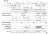
- FIG. 8 is a diagram illustrating an exemplary timing chart during reconfiguration of the evaluation calculation units according to said aspects.
- the travel plan parameter generation/selection unit 24a firstly reads, from the memory 40, the circuit data 43 for reconfiguration of the evaluation calculation units 141 to 14M, in period 2.
- the content of the circuit data 43 is circuit data A.
- the travel plan parameter generation/selection unit 24a After reading the circuit data 43 is completed, the travel plan parameter generation/selection unit 24a internally holds the circuit data 43. Then, the travel plan parameter generation/selection unit 24a activates the reconfiguration instruction 27 to output the information 28 about calculation units to be reconfigured and the reconfiguration circuit data 33 to the reconfiguration control unit 16a.
- the content of the reconfiguration circuit data 33 is the circuit data A having been read from the memory 40 as described above.
- the reconfiguration control unit 16a activates the reconfiguration completion signal 30. After confirming the activation of the reconfiguration completion signal 30, the travel plan parameter generation/selection unit 24a deactivates the reconfiguration instruction 27. Thus, the reconfiguration processing for the evaluation calculation units 141 to 14M is completed.
- the travel plan parameter generation/selection unit 24a activates the reconfiguration instruction 27 and outputs the information 28 about calculation units to be reconfigured and the reconfiguration circuit data 33 to the reconfiguration control unit 16a.
- the content of the reconfiguration circuit data 33 is the circuit data A as in period 2. Note that since the circuit data A is held in the travel plan parameter generation/selection unit 24a in period 2, processing for reading the circuit data A from the memory 40 does not occur in period 3.
- the reconfiguration control unit 16a reconfigures the evaluation calculation units 14M+1 to 14N and activates the reconfiguration completion signal 30 after completion of the reconfiguration. After confirming the activation of the reconfiguration completion signal 30, the travel plan parameter generation/selection unit 24a deactivates the reconfiguration instruction 27. Thus, the reconfiguration processing for the evaluation calculation units 14M+1 to 14N is completed.
- the circuit data 43 read from the memory 40 is held in the travel plan parameter generation/selection unit 24a, and the circuit data is transmitted from the travel plan parameter generation/selection unit 24a to the reconfiguration control unit 16a.
- the evaluation calculation units 141 to 14M or 14M+1 to 14N for which the reconfiguration has been performed may be configured to output evaluation results almost simultaneously with completion of the reconfiguration so that the travel plan parameter generation/selection unit 24a outputs the travel plan parameter to the evaluation calculation units from which the results are output.
- configurations, functions, processing units, processing means, of the like described above may be partially or wholly achieved by hardware, such as a designed integrated circuit.
- each of the above-described configurations, functions, or the like may be achieved by software through interpreting and executing a program for achieving each function by a processor.
- Information such as programs, tables, files which achieve functions can be stored in a recording device, such as memory, hard disk, or solid state drive (SSD) or a recording medium, such as IC card, SD card, or DVD.
- SSD solid state drive
- the number of the evaluation calculation units 141 to 14M to be reconfigured first can be appropriately set depending on an application target. Furthermore, the number of the evaluation calculation units 141 to 14M to be reconfigured first can be changed according to the type of control operation.
- traveling of the vehicle which is switched from traveling on the straight road to traveling on the road curving to the right, has been described.
- the present invention is also applicable to a change in traveling, that is, from traveling on a local road to traveling on a highway, from traveling on a highway to traveling on a local road, from stopping to traveling, from traveling to stopping, or the like.
Landscapes
- Engineering & Computer Science (AREA)
- Radar, Positioning & Navigation (AREA)
- Remote Sensing (AREA)
- Automation & Control Theory (AREA)
- Physics & Mathematics (AREA)
- General Physics & Mathematics (AREA)
- Human Computer Interaction (AREA)
- Transportation (AREA)
- Mechanical Engineering (AREA)
- Traffic Control Systems (AREA)
- Business, Economics & Management (AREA)
- Health & Medical Sciences (AREA)
- Artificial Intelligence (AREA)
- Evolutionary Computation (AREA)
- Game Theory and Decision Science (AREA)
- Medical Informatics (AREA)
- Aviation & Aerospace Engineering (AREA)
- Navigation (AREA)
Description
- The present invention relates to an electronic control device.
- An electronic control device for autonomously driving a vehicle performs a process of calculating a travel plan for traveling in an optimal path and at an optimal speed to a destination in addition to a process of perceiving a road sign or an obstacle. In order to calculate an optimal travel plan in consideration of ride comfort or travel time while avoiding obstacles, a large amount of calculation is required, and a calculation unit with a large calculation capacity is required to achieve the large amount of calculation.
- As a technique for improving the calculation capacity of the calculation unit, a method using dynamic reconfiguration is known. The dynamic reconfiguration is a technique for changing a calculation circuit configuration in a reconfigurable circuit being operated. Using this dynamic reconfiguration, the calculation circuit is changed depending on the situation, and even a small-scale reconfigurable circuit can have a large calculation capacity.
-
PTL 1 is disclosed as a background art in this technical field. As described inPTL 1, "acontrol unit 13 controls a dynamicreconfiguration control unit 16 on the basis of information from a sensor 18 in a vehicle to reconfigure a circuit ofimage processing hardware 11, thereby always enabling image processing depending on a driving environment. Thecontrol unit 13 controls an external device 19, such as a headlight or a brake, on the basis of information to which image processing is performed as described above". Further relevant prior art is described in the following documents - SHANKER SHREEJITH ET AL:"Reconfigurable Computing in Next-Generation Automative Networks", IEEE EMBEDDED SYSTEMS LETTERS, IEEE, USA, vol.5, no.1, 20 January 2013, pages 12-15, and
US 2010/010706 A1 . - PTL 1:
JP 2005-35396 A - In the technique described in
PTL 1, the dynamic reconfiguration is performed to change the configuration of an image processing circuit in a reconfigurable circuit and processing parameters depending on a driving state. - However, the circuit is configured not to perform calculation during the dynamic reconfiguration, and alternative processing, such as stopping an output therefrom or directly outputting a previous calculated value, is required. When such alternative processing is performed in travel plan calculation, if a new obstacle is discovered during dynamic reconfiguration, the change of the vehicle trajectory will be delayed, the possibility of collision with the obstacle will increase, and suddenly turning a steering wheel or sudden deceleration may have to be carried out.
- An object of the present invention is to achieve an electronic control device capable of calculating an optimal travel plan even during dynamic reconfiguration of a calculation circuit configuration.
- In order to achieve the above object, the present invention is configured as follows.
- In particular it is provided an electronic control device having the features defined in
claim 1. Further aspects are defined in the dependent claims. Advantageous Effects of Invention - According to the present invention, an electronic control device capable of calculating an optimal travel plan even during dynamic reconfiguration of a calculation circuit configuration can be achieved.
- Problems, configurations, and effects other than those in the above description will be made clear in the following description of the embodiments.
-
- [
FIG. 1] FIG. 1 is a diagram illustrating a configuration example of an electronic control device and peripheral circuits according to a first embodiment of the present invention. - [
FIG. 2] FIG. 2 is a table illustrating an example of steering angles and accelerations/decelerations of a host vehicle as travel plan parameters. - [
FIG. 3] FIG. 3 is diagrams each illustrating an example of a risk map. - [
FIG. 4] FIG. 4 is diagrams each illustrating an example of risk assessment calculated in travel plan evaluation. - [
FIG. 5] FIG. 5 is diagrams each illustrating an example of a size of a risk map holding area in a driving state. - [
FIG. 6] FIG. 6 is a diagram illustrating an exemplary timing chart during reconfiguration of evaluation calculation units. - [
FIG. 7] FIG. 7 is a diagram illustrating a configuration example of an electronic control device and peripheral circuits. - [
FIG. 8] FIG. 8 is a diagram illustrating an exemplary timing chart during reconfiguration of evaluation calculation units. - Hereinafter, the present invention will be described with reference to the accompanying drawings.
- The invention as defined in the independent claims In the present invention, an example of an electronic control device will be described which is configured to continue travel plan calculation even during dynamic reconfiguration in a vehicle.
-
FIG. 1 is a diagram illustrating a configuration example of the electronic control device and peripheral circuits according to the present invention. - In
FIG. 1 , theelectronic control device 1 calculates a travel plan to a destination by using contents set by an autonomousdrive setting unit 2, sensor values output from a plurality ofsensors 3, information output from acommunication device 4, host vehicle position information output from a vehicle position information acquisition unit 5, and map information stored in a mapinformation storage unit 6. - Then, the
electronic control device 1 outputs a control instruction value for achieving the calculated travel plan to a plurality ofvehicle control devices 7. Each of thevehicle control devices 7 includes, for example, an engine, a transmission, a brake, a steering device, and an electronic control device for controlling the engine, transmission, brake, and the steering device. - The autonomous
drive setting unit 2 is a device for an occupant of the vehicle to set a destination, a route, traveling speed, and the like during autonomous driving. The autonomousdrive setting unit 2 includes an input device (not illustrated) for the occupant to perform setting. The input device includes, for example, a physical input device, such as a button or a touch panel, a gesture input device using a camera or infrared sensor, or a voice input device. - The autonomous
drive setting unit 2 outputs the information input by the occupant to theelectronic control device 1 via the input device. - Each of the
sensor 3 is a sensor for acquiring external information or vehicle state information, and includes, for example, a camera, a radar, an ultrasonic sensor, an acceleration sensor, a yaw rate sensor, or a wheel speed sensor. Thesensor 3 outputs, as the sensor value, the acquired information to theelectronic control device 1. - The
communication device 4 communicates with the outside of the vehicle, for example, another vehicle or an infrastructure system and outputs information from outside the vehicle to theelectronic control device 1. - The vehicle position information acquisition unit 5 is a device for acquiring the position of a host vehicle by using a radio wave from a navigation satellite, such as a global positioning system (GPS). The vehicle position information acquisition unit 5 outputs acquired host vehicle position information to the
electronic control device 1. - The vehicle position information acquisition unit 5 may acquire the host vehicle position information by using a positioning system other than the GPS.
- The map information stored in the map
information storage unit 6 is map data used for autonomous driving and includes, for example, a road width, the number of lanes, gradient, the curvature of a curve, the shape of an intersection, and speed limit information. InFIG. 1 , the map information is stored outside theelectronic control device 1 but may be stored inside theelectronic control device 1. - The
electronic control device 1 internally includes areconfigurable circuit 10, acontroller 20, and amemory 40. Thereconfigurable circuit 10 is a circuit having an internal circuit, the configuration of which is changeable, and includes, for example, a filed programmable gate array (FPGA) or a complex programmable logic device (CPLD). - The
reconfigurable circuit 10 internally includes a surroundingsituation perception unit 11, a riskmap generation unit 12, a travelplan evaluation unit 13, and areconfiguration control unit 16. - On the basis of the sensor values output from the
sensors 3 and the information output from thecommunication device 4, the surroundingsituation perception unit 11 perceives situations around the host vehicle, for example, the contents of road signs, traffic signal situations, other vehicles around the host vehicle, and pedestrian situations. - Then, the surrounding
situation perception unit 11 outputs peripheral perception information to the riskmap generation unit 12. - The risk
map generation unit 12 generates arisk map 41 used for travel plan evaluation by using the host vehicle position information output from the vehicle position information acquisition unit 5, the map information stored in the mapinformation storage unit 6, and the peripheral perception information output from the surroundingsituation perception unit 11. Details of therisk map 41 will be described later with reference toFIG. 3 . The riskmap generation unit 12 stores the generatedrisk map 41 in thememory 40. - Note that, the processing of the surrounding
situation perception unit 11 and the riskmap generation unit 12 is performed in thereconfigurable circuit 10, but the processing may be performed in thecontroller 20. Furthermore, the processing may be performed by another processing device inside theelectronic control device 1 or a processing device outside theelectronic control device 1. - The travel
plan evaluation unit 13 includes a plurality of independentevaluation calculation units 141 to 14N. The number of theevaluation calculation units 141 to 14N is set to N. - In addition, each of the
evaluation calculation units 141 to 14N includes a vehicle model (not illustrated) and a riskmap holding area 15 therein. In the riskmap holding area 15, therisk map 41 used for the travel plan evaluation is partially stored. - The
evaluation calculation units 141 to 14N use the host vehicle position information output from the vehicle position information acquisition unit 5, thetravel plan parameters 251 to 25N output from thecontroller 20, and the vehicle model in the evaluation calculation unit to calculate the traveling trajectory, traveling speed, and the like of the vehicle. Thereafter, theevaluation calculation units 141 to 14N evaluates thetravel plan parameters 251 to 25N by using the calculated traveling trajectory and traveling speed of the vehicle,target point information 23 output from thecontroller 20, risk map information stored in the risk map holding areas, andoutputs evaluation results 261 to 26N to thecontroller 20. Details of the contents of this evaluation will be described later. - Each of the
evaluation calculation units 141 to 14N includes the riskmap holding area 15. However, the number of the riskmap holding areas 15 for the evaluation calculation units does not necessarily correspond one-to-one with the number of theevaluation calculation units 141 to 14N, and a riskmap holding area 15 may be shared between the plurality ofevaluation calculation units 141 to 14N. However, a plurality of the riskmap holding areas 15 are required. - The
reconfiguration control unit 16 reconfigures theevaluation calculation units 141 to 14N. When areconfiguration instruction 27 is output from thecontroller 20, thereconfiguration control unit 16 selects data matching reconfigurationcircuit data information 29 from amongcircuit data 421 to 42X stored in thememory 40, and reads the data, ascircuit data 43, from thememory 40. On the basis of thecircuit configuration data 43, thereconfiguration control unit 16 reconfigures evaluation calculation units of theevaluation calculation units 141 to 14N corresponding toinformation 28 about calculation units to be reconfigured. After the reconfiguration is completed, thereconfiguration control unit 16 outputs areconfiguration completion signal 30 to thecontroller 20. - The
controller 20 internally includes a drivingstate control unit 21, a travel plan parameter generation/selection unit 24, and aparameter conversion unit 32. - The driving
state control unit 21 determines a current driving state on the basis of autonomous driving setting information output from the autonomousdrive setting unit 2, the host vehicle position information output from the vehicle position information acquisition unit 5, and the map information, and determines a target point in the travel plan. - Then, the determined driving state 22 (signal indicating the driving state) is output to the path parameter generation/
selection unit 24, and atarget point 23 determined is output to the travelplan evaluation unit 13. - The driving
state 22 includes, for example, a straight traveling state, a right-hand curve state, a left-hand curve state, a right turning state, a left turning state, and a preceding vehicle following state. Furthermore, the invention as claimed employs a method of calculating a travel plan for each of sections obtained by partitioning a route to a destination which is set by the autonomousdrive setting unit 2 into several sections, and the above-describedtarget point 23 represents a target coordinate position in each section. - Note that, the processing of the driving
state control unit 21 is performed by thecontroller 20, but this processing may be performed by thereconfigurable circuit 10. Furthermore, this processing may be performed by another processing device inside theelectronic control device 1 or a processing device outside theelectronic control device 1. Furthermore, it is also possible to arrange the drivingstate control unit 21 not inside thecontroller 20 but outside thecontroller 20, - The travel plan parameter generation/
selection unit 24 generates thetravel plan parameters 251 to 25N and outputs thetravel plan parameters 251 to 25N to theevaluation calculation units 141 to 14N. Thetravel plan parameters 251 to 25N are information for calculating the traveling trajectory and traveling speed of the vehicle and include, for example, a steering angle and acceleration/deceleration of the host vehicle, and a coordinate position of the host vehicle at a certain time. -
FIG. 2 is a table illustrating an example of steering angles and accelerations/decelerations of the host vehicle as the travel plan parameters. In an example illustrated inFIG. 2 , the steering angle and acceleration/deceleration of the host vehicle are defined at every Δt seconds up to nΔt seconds. Furthermore, on the basis ofcalculation results 261 to 26N output from theevaluation calculation units 141 to 14N, the travel plan parameter generation/selection unit 24 selects a best travel plan parameter and outputs the selected travel plan parameter, as an optimaltravel plan parameter 31, to theparameter conversion unit 32. - In order to reconfigure the
evaluation calculation units 141 to 14N, the travel plan parameter generation/selection unit 24 also performs processing of outputting thereconfiguration instruction 27, theinformation 28 about calculation units to be reconfigured, and the reconfigurationcircuit data information 29 to thereconfiguration control unit 16, in addition to the processing described above. - On the basis of the optimal
travel plan parameter 31 output from the travel plan parameter generation/selection unit 24, theparameter conversion unit 32 calculates an instruction value for eachvehicle control device 7 and outputs the calculated instruction value as the control instruction value to thevehicle control device 7. - The
memory 40 internally includes therisk map 41 and thecircuit data 421 to 42X. X pieces ofcircuit data 421 to 42X are stored in thememory 40, but this number of data is merely an example. - The
risk map 41 and thecircuit data 421 to 42X are stored in thesame memory 40, but therisk map 41 and thecircuit data 421 to 42X may be separately stored in a plurality of memories. -
FIG. 3 is diagrams each illustrating an example of the risk map. In (a) on the left side ofFIG. 3 , a current situation around the host vehicle is illustrated, and one vehicle is in front of the host vehicle and two vehicles (other vehicles) (shown in dark) are in the opposite lanes. This state is represented in the risk map, as in the risk map (current) illustrated in (b) ofFIG. 3 . A portion including an obstacle such as a vehicle has a high risk (black) and a portion including a road with no obstacle has a low risk (white (squares)). Furthermore, a portion through which no vehicle is allowed to pass, such as a sidewalk, also has a high risk (black). - In addition to the current state, the risk
map generation unit 12 also creates a future risk map by prediction. The future risk map is created to determine whether the host vehicle collides with an obstacle at a future host vehicle position in the travel plan evaluation. The riskmap generation unit 12 predicts a future position of a peripheral object according to the moving speed of the object around the host vehicle and creates the future risk map on the basis of the future position. In an example of (c) ofFIG. 3 , a risk map after M seconds from the current time is illustrated, but the vehicle in front of the host vehicle and vehicles in the opposite lanes are predicted to move for M seconds, and the positions having the higher risk (black) are different from those in the current risk map. - The number of the risk maps is determined depending on a time interval and a maximum time in the travel plan parameter. As illustrated in
FIG. 2 , in a case where the travel plan parameters are defined at every Δt seconds for nΔt seconds, it is necessary as well to create the risk maps at every Δt seconds for nΔt seconds. Therefore, the number of the risk maps generated in this case is n. - An example of a travel plan evaluation calculation performed by the
evaluation calculation units 141 to 14N will be described. - The
evaluation calculation units 141 to 14N perform calculation of the evaluation results of the travel plan on the basis of the following Formula (1). A smaller calculation result of Formula (1) is determined to be a more suitable travel plan parameter. Therefore, in this example, the travel plan parameter generation/selection unit 24 selects a travel plan parameter having the smallest evaluation result as the optimaltravel plan parameter 31.
- In Formula (1), H1 is a risk assessment value during traveling. H2 and H3 will be described later.
- In this risk assessment, risks are calculated at time intervals (Δt seconds in
FIG. 2 ) according to the travel plan parameter, the risks in the respective time blocks are accumulated, and the assessment value is calculated. This risk assessment is performed by using the risk map information stored in the riskmap holding area 15 in each of theevaluation calculation units 141 to 14N. -
FIG. 4 is diagrams each illustrating an example of risk assessment in travel plan evaluation calculation. Note that the situation around the vehicle inFIG. 4 is the same as that inFIG. 3 . In (a) on the left side ofFIG. 4 , a diagram of a state after t = 0 seconds is illustrated. In the state after t = 0 seconds, all risk map information about the host vehicle position shows a state of low risk (white), and the risk at this time is small. - In (b) on the right side of
FIG. 4 , a diagram of a state after t = xΔt seconds is illustrated. The host vehicle and the other vehicles are traveling straight ahead in the movement directions thereof, and this map has a state different from the map after t = 0 seconds. After t = xΔt seconds, the host vehicle is in contact with the vehicle traveling ahead, and the host vehicle position partially has a state of high risk (black). Therefore, the risk at this time is high. - In this way, when the travel plan parameter takes such a traveling trajectory that the host vehicle collides with the obstacle, H1 has a large value. Therefore, such a travel plan parameter is not selected as the optimal
travel plan parameter 31. - In Formula (1), H2 is an assessment value of a travel time up to a point indicated by the
target point information 23. The shorter the travel time, the smaller the value of H2. - In Formula (1), H3 is a value of ride comfort assessment during traveling. The ride comfort assessment is performed by using, for example, a longitudinal acceleration of the vehicle or a lateral acceleration of the vehicle in each time block during traveling. The better the ride comfort, the smaller the value of H3.
- As described above, in the evaluation of the travel plan parameters, the risk H1, travel time H2, and ride comfort H3 during traveling are comprehensively evaluated. The travel plan parameters having results of no collision with the obstacle, a shorter travel time, and better ride comfort have a smaller value of the evaluation result.
- Reconfiguration of the
evaluation calculation units 141 to 14N makes a large change in the riskmap holding areas 15.FIG. 5 is diagrams each illustrating an example of a size of the riskmap holding area 15 in each driving state. InFIG. 5 , (a) ofFIG. 5 is a diagram illustrating the drivingstate 22 having the left-hand curve state. - In
FIG. 5 , (b) ofFIG. 5 is a diagram in which the drivingstate 22 has the straight traveling state, and (c) ofFIG. 5 is a diagram illustrating the drivingstate 22 having the right-hand curve state. - As illustrated in (a) of
FIG. 5 , when the drivingstate 22 is in the left-hand curve state, the host vehicle is considered not to have a trajectory along which the host vehicle makes a large rightward movement from a current position. That is, a risk map non-use area (shaded portion) of the risk map, positioned over the right side from the host vehicle, is not used. Therefore, a left side portion of the risk map excluding the risk map non-use area is enough for the size of the riskmap holding area 15 in the left-hand curve state. - As illustrated in (b) of
FIG. 5 , when the drivingstate 22 is in the straight traveling state, the host vehicle is considered not to have a trajectory along which the host vehicle makes a large lateral movement (in a direction perpendicular to the movement direction). In other words, portions (portions of the risk map non-use areas) of the risk map, positioned over the right and left sides from the host vehicle is not used. Therefore, a center portion of the risk map excluding the risk map non-use areas is enough for the size of the riskmap holding area 15 in the straight traveling state. - As illustrated in (c) of
FIG. 5 , when the driving state is in the right-hand curve state, the host vehicle is considered not to have a trajectory along which the host vehicle makes a large leftward movement from a current position. Therefore, as in the left-hand curve state and the straight traveling state, a right side portion of the risk map excluding the risk map non-use area is enough for the size of the riskmap holding area 15. - Dynamic reconfiguration of the
evaluation calculation units 141 to 14N depending on the driving state for optimization of the size of the riskmap holding area 15 causes a reduction in circuit area of theevaluation calculation units 141 to 14N, compared with risk maps having the large riskmap holding areas 15 corresponding to all driving states. Therefore, it is possible to increase the number of theevaluation calculation units 141 to 14N even in the same circuit area and a calculation capacity for the travel plan evaluation can be increased. -
FIG. 6 is a diagram illustrating an exemplary timing chart during reconfiguration of the evaluation calculation units according to the first embodiment. - In
FIG. 6 ,period 1 is a period in which theevaluation calculation units 141 to 14N are not reconfigured but perform normal processing. In this period, the drivingstate 22 is in the straight traveling state, and the travel plan parameter generation/selection unit 24 firstly outputs P111 as thetravel plan parameter 251 to theevaluation calculation unit 141. - In addition, the travel plan parameter generation/
selection unit 24 outputs P211 to PN11 independently as thetravel plan parameters 251 to 25N to the other evaluation calculation units 142 to 14N. Theevaluation calculation units 141 to 14N evaluate the respective travel plan parameters and output corresponding evaluation results to the travel plan parameter generation/selection unit 24. For example, Rill of theevaluation result 261 represents a result of an evaluation of the travel plan parameter P111, and RN11 of theevaluation result 26N represents a result of an evaluation of the travel plan parameter PN11. - Thereafter, the travel plan parameter generation/
selection unit 24 changes the values of thetravel plan parameters 251 to 25N (P112 to PN12) and outputs the values to theevaluation calculation units 141 to 14N. Theevaluation calculation units 141 to 14N evaluate the respectivetravel plan parameters 251 to 25N (P112 to PN12) and output thecorresponding evaluation results 261 to 26N (R112 to RN12) to the travel plan parameter generation/selection unit 24. - After completion of the evaluation performed by a defined number of times (1 to L), the travel plan parameter generation/
selection unit 24 uses the evaluation results 261 to 26N (Rill to R11L, ..., RN11 to RN1L) obtained from theevaluation calculation units 141 to 14N, selecting the best travel plan parameter having the best evaluation result from among thetravel plan parameters 251 to 25N (Pill to P11L, ..., PN11 to PN1L) as the optimaltravel plan parameter 31. In the example ofFIG. 6 , the travel plan parameter P11L is selected as the optimaltravel plan parameter 31. - The next driving state is the right-hand curve state, and this right-hand curve state is divided into the
first period 2 and thenext period 3.Period 2 is set as a path update period. - In
period 2, the drivingstate 22 is switched from the straight traveling state to the right-hand curved state. In response to this, the travel plan parameter generation/selection unit 24 reconfigures some of theevaluation calculation units 141 to 14N. - In the example of
FIG. 6 , M evaluation calculation units of theevaluation calculation units 141 to 14M are reconfigured duringperiod 2. In order to perform the reconfiguration, the travel plan parameter generation/selection unit 24 activates thereconfiguration instruction 27 to transmit information on starting the reconfiguration to thereconfiguration control unit 16. In addition, the travel plan parameter generation/selection unit 24 sets numbers of evaluation calculation units to be reconfigured in theinformation 28 about calculation units to be reconfigured, and outputs theinformation 28 about calculation units to be reconfigured to thereconfiguration control unit 16. In this example, the values of theinformation 28 about calculation units to be reconfigured are theevaluation calculation units 141 to 14M. - To the
evaluation calculation units 141 to 14M subjected to the reconfiguration, thetravel plan parameter 251 to 25M are not output from the travel plan parameter generation/selection unit 24. To theevaluation calculation units 14M+1 to 14N, the travel plan parameters 25M+1 to 25N are output from the travel plan parameter generation/selection unit 24. - In addition, the travel plan parameter generation/
selection unit 24 outputs, as the reconfigurationcircuit data information 29, circuit data information for performing the reconfiguration to thereconfiguration control unit 16. In this example, in order to reconfigure the evaluation calculation units into a circuit configuration corresponding to the right-hand curve state, circuit data A selected fromcircuit data 1 to X is set to the circuit data reconfigurationcircuit data information 29. - The
reconfiguration control unit 16 receives thereconfiguration instruction 27,information 28 about calculation units to be reconfigured, and reconfigurationcircuit data information 29 which are output from the travel plan parameter generation/selection unit 24, and reads thecircuit data 43 corresponding to the reconfigurationcircuit data information 29 from thememory 40. In this example, thecircuit data 43 is the circuit data A. Then, thereconfiguration control unit 16 reconfigures theevaluation calculation units 141 to 14M corresponding to theinformation 28 about calculation units to be reconfigured. - During the reconfiguration, the
evaluation calculation units 141 to 14M output indeterminate values. After the reconfiguration of theevaluation calculation units 141 to 14M is normally completed, thereconfiguration control unit 16 outputs thereconfiguration completion signal 30 to the travel plan parameter generation/selection unit 24. - The travel plan parameter generation/
selection unit 24 receives the output of thereconfiguration completion signal 30 and deactivates thereconfiguration instruction 27. Thus, the reconfiguration processing inperiod 2 is completed. - During
period 2, even while theevaluation calculation units 141 to 14M are being reconfigured, the other evaluation calculation units (theevaluation calculation units 14M+1 to 14N) evaluate the travel plan parameters as usual. The travel plan parameter generation/selection unit 24 selects the optimaltravel plan parameter 31 on the basis of the evaluation results 26M+1 to 26N output from theevaluation calculation units 14M+1 to 14N. In the example ofFIG. 6 , the optimaltravel plan parameter 31 inperiod 2 is PN2L. - In
period 3, followingperiod 2, the drivingstate 22 is in the right-hand curve state. At this time, the travel plan parameter generation/selection unit 24 reconfigures theevaluation calculation units 14M+1 to 14N which have not been reconfigured inperiod 2. Inperiod 3, the travel plan parameters 25M+1 to 25N are not output from the travel plan parameter generation/selection unit 24 to theevaluation calculation units 14M+1 to 14N which are to be reconfigured. - The method for reconfiguration is performed as described in
period 2, and the travel plan parameter generation/selection unit 24 activates thereconfiguration instruction 27 and sets theevaluation calculation units 14M+1 to 14N in theinformation 28 about calculation units to be reconfigured, and sets the circuit data A as the reconfigurationcircuit data information 29. - The
reconfiguration control unit 16 receives thereconfiguration instruction 27,information 28 about calculation units to be reconfigured, and reconfigurationcircuit data information 29 which are output from the travel plan parameter generation/selection unit 24 and reads the circuit data A corresponding to the reconfigurationcircuit data information 29 from thememory 40, that is, from thecircuit data 43. - Then, the
reconfiguration control unit 16 reconfigures theevaluation calculation units 14M+1 to 14N corresponding to theinformation 28 about calculation units to be reconfigured. During the reconfiguration, theevaluation calculation units 14M+1 to 14N output indeterminate values. After the reconfiguration is normally completed, thereconfiguration control unit 16 outputs thereconfiguration completion signal 30 to the travel plan parameter generation/selection unit 24. - The travel plan parameter generation/
selection unit 24 receives the output of thereconfiguration completion signal 30 and deactivates thereconfiguration instruction 27. Thus, the reconfiguration processing inperiod 3 is completed. - During
period 3, even while theevaluation calculation units 14M+1 to 14N are being reconfigured, the other evaluation calculation units (theevaluation calculation units 141 to 14M) evaluate the travel plan parameters as usual. The travel plan parameter generation/selection unit 24 selects the optimaltravel plan parameter 31 on the basis of the evaluation results 261 to 26M output from theevaluation calculation units 141 to 14M. In the example ofFIG. 6 , the optimaltravel plan parameter 31 inperiod 3 is PM3L. - Note that in the example of
FIG. 6 , theevaluation calculation units 141 to 14N are divided into two blocks for reconfiguration, but may be further divided to perform reconfiguration a larger number of times. - Furthermore, in the example of
FIG. 6 , duringperiod 2 andperiod 3, the travel plan parameter generation/selection unit 24 does not output the travel plan parameters to the evaluation calculation units for which the reconfiguration has been completed during a corresponding period, but after completion of the configuration, the evaluation calculation units can operate normally, and, immediately after the completion of the reconfiguration, thetravel plan parameters 251 to 25M or 25M+1 to 25N may be input to the reconfiguredevaluation calculation units 141 to 14M or 14M+1 to 14N to start the evaluation operation of the travel plan parameters. - That is, the travel plan parameter generation/
selection unit 24 may be configured to determine theevaluation calculation units 141 to 14M or 14M+1 to 14N for which the reconfiguration has been finished, and output the evaluation results almost simultaneously with completion of the reconfiguration. The travel plan parameter generation/selection unit 24 may also be configured to output the travel plan parameters to the evaluation calculation units from which the evaluation results are output. - With this configuration, it is possible to increase the number of evaluation calculation units operating simultaneously in a control cycle to increase the number of parameters to be evaluated. Thus, the operation of the vehicle can be controlled more optimally.
- As described above, when the driving
state 22 changes, the travel plan parameter generation/selection unit 24 divides theevaluation calculation units 141 to 14N into a plurality of blocks for reconfiguration via thereconfiguration control unit 16. - Dividing the reconfiguration of the
evaluation calculation units 141 to 14N a plurality of times enables continuation of evaluation of the travel plan in the rest of the evaluation calculation units, even while some of theevaluation calculation units 141 to 14N are being reconfigured. - Therefore, according to the first embodiment, it becomes unnecessary to perform alternative processing, such as outputting the travel plan having been evaluated last time. Thus, an electronic control device can be achieved which is configured so that even though the situation around the host vehicle is changed during the reconfiguration of some of the
evaluation calculation units 141 to 14N, the travel plan can be changed promptly according to the situation, and even during the dynamic reconfiguration of the calculation circuit configuration, an optimal travel plan can be calculated. - Aspects not covered by the invention as claimed Next, aspects that do not correspond to the invention as defined in the independent claims will be described. Said aspects are a modification of the invention as claimed.
-
FIG. 7 is a diagram illustrating a configuration example of an electronic control device and peripheral circuits according to said aspects. - Note that the same reference numerals are given to the same elements as those in invention as claimed and described above, and the description of the same elements will be omitted.
- In
FIG. 7 , when reconfiguring theevaluation calculation units 141 to 14N, a travel plan parameter generation/selection unit 24a reads, as thecircuit data 43, any of thecircuit data 421 to 42X, from thememory 40 and stores thecircuit data 43 in the travel plan parameter generation/selection unit 24a. - Then, the travel plan parameter generation/selection unit 24a outputs, as
reconfiguration circuit data 33, thecircuit data 43 held therein to areconfiguration control unit 16a, instead of the reconfigurationcircuit data information 29 illustrated inFIG. 1 . - When the
reconfiguration instruction 27 is output from the travel plan parameter generation/selection unit 24, thereconfiguration control unit 16a illustrated inFIG. 7 reconfigures the evaluation calculation units set in theinformation 28 about calculation units to be reconfigured, on the basis of thereconfiguration circuit data 33 output from the travel plan parameter generation/selection unit 24a. -
FIG. 8 is a diagram illustrating an exemplary timing chart during reconfiguration of the evaluation calculation units according to said aspects. - In
FIG. 8 , in order to reconfigure theevaluation calculation units 141 to 14M, the travel plan parameter generation/selection unit 24a firstly reads, from thememory 40, thecircuit data 43 for reconfiguration of theevaluation calculation units 141 to 14M, inperiod 2. In this example, the content of thecircuit data 43 is circuit data A. - After reading the
circuit data 43 is completed, the travel plan parameter generation/selection unit 24a internally holds thecircuit data 43. Then, the travel plan parameter generation/selection unit 24a activates thereconfiguration instruction 27 to output theinformation 28 about calculation units to be reconfigured and thereconfiguration circuit data 33 to thereconfiguration control unit 16a. Here, the content of thereconfiguration circuit data 33 is the circuit data A having been read from thememory 40 as described above. - When the reconfiguration of the evaluation calculation units 141-14M set in the
information 28 about calculation units to be reconfigured is completed, thereconfiguration control unit 16a activates thereconfiguration completion signal 30. After confirming the activation of thereconfiguration completion signal 30, the travel plan parameter generation/selection unit 24a deactivates thereconfiguration instruction 27. Thus, the reconfiguration processing for theevaluation calculation units 141 to 14M is completed. - In
period 3, for reconfiguration of theevaluation calculation units 14M+1 to 14N, the travel plan parameter generation/selection unit 24a activates thereconfiguration instruction 27 and outputs theinformation 28 about calculation units to be reconfigured and thereconfiguration circuit data 33 to thereconfiguration control unit 16a. - Here, the content of the
reconfiguration circuit data 33 is the circuit data A as inperiod 2. Note that since the circuit data A is held in the travel plan parameter generation/selection unit 24a inperiod 2, processing for reading the circuit data A from thememory 40 does not occur inperiod 3. - After that, the
reconfiguration control unit 16a reconfigures theevaluation calculation units 14M+1 to 14N and activates thereconfiguration completion signal 30 after completion of the reconfiguration. After confirming the activation of thereconfiguration completion signal 30, the travel plan parameter generation/selection unit 24a deactivates thereconfiguration instruction 27. Thus, the reconfiguration processing for theevaluation calculation units 14M+1 to 14N is completed. - As described above, in said aspects, the
circuit data 43 read from thememory 40 is held in the travel plan parameter generation/selection unit 24a, and the circuit data is transmitted from the travel plan parameter generation/selection unit 24a to thereconfiguration control unit 16a. - Accordingly, since the number of accesses to the
memory 40 is reduced as compared with the invention as claimed, it is possible to perform another memory access, for example, update processing for therisk map 41, earlier. - Therefore, as in the invention as claimed, it is possible to achieve an electronic control device capable of calculating an optimal travel plan even during dynamic reconfiguration of a calculation circuit configuration.
- In said aspects as well as in the invention as claimed, the
evaluation calculation units 141 to 14M or 14M+1 to 14N for which the reconfiguration has been performed may be configured to output evaluation results almost simultaneously with completion of the reconfiguration so that the travel plan parameter generation/selection unit 24a outputs the travel plan parameter to the evaluation calculation units from which the results are output. - Still furthermore, the configurations, functions, processing units, processing means, of the like described above may be partially or wholly achieved by hardware, such as a designed integrated circuit.
- In addition, each of the above-described configurations, functions, or the like may be achieved by software through interpreting and executing a program for achieving each function by a processor. Information such as programs, tables, files which achieve functions can be stored in a recording device, such as memory, hard disk, or solid state drive (SSD) or a recording medium, such as IC card, SD card, or DVD.
- The examples described above are examples in which the present invention is applied to vehicle control but are also applicable to any other than vehicle control (e.g., ship, robot, etc.).
- In addition, in the above examples, the number of the
evaluation calculation units 141 to 14M to be reconfigured first can be appropriately set depending on an application target. Furthermore, the number of theevaluation calculation units 141 to 14M to be reconfigured first can be changed according to the type of control operation. - In the above examples, traveling of the vehicle, which is switched from traveling on the straight road to traveling on the road curving to the right, has been described. However, the present invention is also applicable to a change in traveling, that is, from traveling on a local road to traveling on a highway, from traveling on a highway to traveling on a local road, from stopping to traveling, from traveling to stopping, or the like.
-
- 1 electronic control device
- 2 autonomous drive setting unit
- 3 sensor
- 4 communication device
- 5 vehicle position information acquisition unit
- 6 map information storage unit
- 7 vehicle control device
- 10 reconfigurable circuit
- 13 travel plan evaluation unit
- 15 risk map holding area
- 16, 16a reconfiguration control unit
- 20 controller
- 21 driving state control unit
- 22 driving state
- 24, 24a travel plan parameter generation/selection unit
- 251 to 25N travel plan parameter
- 261 to 26N evaluation result
- 33 reconfiguration circuit data
- 40 memory
- 41 risk map
- 43 circuit data
- 141 to 14N evaluation calculation unit
Claims (5)
- An electronic control device (1) for calculating a travel plan to a destination based on a respective target point in the travel plan for which parameters to steer a host vehicle to said target point are calculated, comprising:a reconfigurable circuit (10),a controller (20), anda memory (40), whereinthe reconfigurable circuit (10) internally includes a surrounding situation perception unit (11), a risk map generation unit (12), a travel plan evaluation unit (13), and a reconfiguration control unit (16), whereinthe travel plan evaluation unit (13) includes a plurality of evaluation calculation units (141 to 14N), whereinthe controller (20) internally includes a driving state control unit (21), a travel plan parameter generation/selection unit (24) and a parameter conversion unit (32), wherein the driving state control unit (21) is configured to determine a driving state on the basis of autonomous driving setting information output from an autonomous drive setting unit (2), host vehicle position information output from a vehicle position information acquisition unit (5), and map information, wherein the driving state includes a straight traveling state, a right-hand curve state, a left-hand curve state, a right turning state, a left turning state, and a preceding vehicle following state, whereinthe travel plan parameter generation/selection unit (24) is configured to generate and to output a travel plan parameter (251 to 25N) to the plurality of evaluation calculation units (141 to 14N), whereinthe memory (40) internally includes a risk map (41) and circuit data (421 to 42X), whereinbased on sensor values output from a plurality of sensors (3) and information output from a communication device (4), the surrounding situation perception unit (11) is configured to perceive information regarding road signs, traffic signals, other vehicles and pedestrians around the host vehicle, and to output the perceived information to the risk map generation unit (12), whereinthe risk map generation unit (12) is configured to generate the risk map (41) for travel plan evaluation by using host vehicle position information output from the vehicle position information acquisition unit (5), map information stored in a map information storage unit (6), and the perceived information output from the surrounding situation perception unit (11), wherein the risk map (41) represents a state around the host vehicle, wherein the risk map (41) includes a high-risk portion and a low-risk portion, wherein the high-risk portion, which represents a portion of the risk map (41) in which an obstacle has been perceived, is marked differently than the low-risk portion, which represents a portion of the risk map (41) in which no obstacle has been perceived, whereinthe risk map generation unit (12) is configured to store the risk map (41) in the memory (40), whereineach evaluation calculation unit (141 to 14N) includes a vehicle model and a risk map holding area (15), in which the risk map (41) for the travel plan evaluation is partially stored, whereinthe evaluation calculation units (141 to 14N) are configured to use the host vehicle position information output from the vehicle position information acquisition unit (5), the travel plan parameter (251 to 25N) output from the controller (20) and the vehicle model to calculate a traveling trajectory and traveling speed of the host vehicle, whereinthe plurality of evaluation calculation units (141 to 14N) are configured to evaluate the travel plan parameter (251 to 25N) by using the calculated traveling trajectory and traveling speed of the host vehicle, target point information (23) output from the controller (20) and the risk map (41) stored in the risk map holding area (15) and to output evaluation results (261 to 26N) to the travel plan parameter generation/selection unit (24), whereinthe travel plan parameter generation/selection unit (24) is configured to use the evaluation results (261 to 26N) in order to select a best travel plan parameter having a best evaluation result from among the travel plan parameter (251 to 25N) and to output the selected travel plan parameter, as an optimal travel plan parameter (31), to the parameter conversion unit (32), whereinthe travel plan parameter generation/selection unit (24), in order to reconfigure the plurality of evaluation calculation units (141 to 14N), is configured to output a reconfiguration instruction (27), an information (28) about evaluation calculation units (141 to 14N) to be reconfigured, and a reconfiguration circuit data information (29) to the reconfiguration control unit (16), whereinthe reconfiguration circuit data information (29), is circuit data information for performing the reconfiguration of the plurality of evaluation calculation units (141 to 14N), wherein,in order to reconfigure the plurality of evaluation calculation units (141 to 14N) into a circuit configuration corresponding to the respective driving state of the vehicle, a respective circuit data is selected from circuit data contained in the memory (40) is set to the circuit data reconfiguration circuit data information (29), whereinthe electronic control device (1) is configured that when the reconfiguration instruction (27) is output from the controller (20), the reconfigurable circuit (10) divides the plurality of evaluation calculation units (141 to 14N) into a plurality of blocks (141 to 14M; 14M+1 to 14N), such that the plurality of evaluation calculation units are divided into evaluation calculation units performing reconfiguration (141 to 14M) within a same period and evaluation calculation units (14M+1 to 14N) performing reconfiguration within another period, and the controller (20) outputs the travel plan parameter (251 to 25N) only to the evaluation calculation units that does not perform reconfiguration (14M+1 to 14N), whereinthe reconfiguration control unit (16) is configured to receive the reconfiguration instruction (27), the information (28) about evaluation calculation units (141 to 14N) to be reconfigured, and the reconfiguration circuit data information (29) which are output from the travel plan parameter generation/selection unit (24), and to read a circuit data (43) corresponding to the reconfiguration circuit data information (29) from the memory (40), and to then reconfigure the evaluation calculation units (141 to 14M) corresponding to the information (28) about evaluation calculation units (141 to 14N) to be reconfigured.
- The electronic control device (1) according to claim 1, wherein
the reconfigurable circuit (10) is configured to supply identical circuit data to the plurality of evaluation calculation units (141 to 14N). - The electronic control device (1) according to any one of claims 1 to 2, wherein the controller (20) is further configured to output the reconfiguration instruction (27) on the basis of a driving state determined by the driving state control unit (21).
- The electronic control device (1) according to claim 1, wherein
the controller (20) is configured to determine evaluation calculation units (141 to 14M) for which reconfiguration has completed within the same period or within the other period to output the travel plan parameter (251 to 25M) to the evaluation calculation units (141 to 14M) for which reconfiguration has completed. - The electronic control device (1) according to any one of claims 1 to 4, wherein
the electronic control device (1) is a vehicle control device used to autonomously drive a vehicle.
Applications Claiming Priority (2)
| Application Number | Priority Date | Filing Date | Title |
|---|---|---|---|
| JP2016225996A JP6713410B2 (en) | 2016-11-21 | 2016-11-21 | Electronic control unit |
| PCT/JP2017/038634 WO2018092539A1 (en) | 2016-11-21 | 2017-10-26 | Electronic control device |
Publications (3)
| Publication Number | Publication Date |
|---|---|
| EP3543864A1 EP3543864A1 (en) | 2019-09-25 |
| EP3543864A4 EP3543864A4 (en) | 2020-12-16 |
| EP3543864B1 true EP3543864B1 (en) | 2024-03-27 |
Family
ID=62146318
Family Applications (1)
| Application Number | Title | Priority Date | Filing Date |
|---|---|---|---|
| EP17870904.4A Active EP3543864B1 (en) | 2016-11-21 | 2017-10-26 | Electronic control device |
Country Status (5)
| Country | Link |
|---|---|
| US (1) | US11125572B2 (en) |
| EP (1) | EP3543864B1 (en) |
| JP (1) | JP6713410B2 (en) |
| CN (1) | CN109983450B (en) |
| WO (1) | WO2018092539A1 (en) |
Families Citing this family (12)
| Publication number | Priority date | Publication date | Assignee | Title |
|---|---|---|---|---|
| JP6810651B2 (en) * | 2017-04-24 | 2021-01-06 | 日立オートモティブシステムズ株式会社 | Electronic control device, logic circuit control method |
| JP7253908B2 (en) * | 2018-12-03 | 2023-04-07 | 日立Astemo株式会社 | vehicle controller |
| US12027039B2 (en) | 2019-12-30 | 2024-07-02 | Subaru Corporation | Mobility information provision system, server, and vehicle |
| US11816988B2 (en) | 2019-12-30 | 2023-11-14 | Subaru Corporation | Mobility information provision system, server, and vehicle |
| US11674819B2 (en) | 2019-12-30 | 2023-06-13 | Subaru Corporation | Mobility information provision system, server, and vehicle |
| US11688279B2 (en) | 2019-12-30 | 2023-06-27 | Subaru Corporation | Mobility information provision system, server, and vehicle |
| US11395208B2 (en) | 2019-12-30 | 2022-07-19 | Subaru Corporation | Mobility information provision system for mobile bodies, server, and vehicle |
| US11900796B2 (en) * | 2019-12-30 | 2024-02-13 | Subaru Corporation | Map generation system |
| US12046140B2 (en) | 2019-12-30 | 2024-07-23 | Subaru Corporation | Mobility information provision system, server, and vehicle |
| US11423780B2 (en) | 2019-12-30 | 2022-08-23 | Subaru Corporation | Traffic control system |
| US11816982B2 (en) | 2019-12-30 | 2023-11-14 | Subaru Corporation | Mobility information provision system, server, and vehicle |
| EP3971526B1 (en) | 2020-09-18 | 2024-05-08 | Zenuity AB | Path planning in autonomous driving environments |
Family Cites Families (39)
| Publication number | Priority date | Publication date | Assignee | Title |
|---|---|---|---|---|
| DE19618804A1 (en) * | 1996-05-10 | 1997-11-13 | Zahnradfabrik Friedrichshafen | Method for evaluating the course of a road in an automatic transmission |
| JP3485755B2 (en) * | 1997-05-22 | 2004-01-13 | アシスト シンコー株式会社 | Automatic guided vehicle control device and automatic guided vehicle control method |
| US9411532B2 (en) * | 2001-09-07 | 2016-08-09 | Pact Xpp Technologies Ag | Methods and systems for transferring data between a processing device and external devices |
| US7657861B2 (en) * | 2002-08-07 | 2010-02-02 | Pact Xpp Technologies Ag | Method and device for processing data |
| WO2004025468A1 (en) * | 2002-09-13 | 2004-03-25 | Hitachi, Ltd. | Semiconductor device |
| US8276135B2 (en) * | 2002-11-07 | 2012-09-25 | Qst Holdings Llc | Profiling of software and circuit designs utilizing data operation analyses |
| JP2005035396A (en) * | 2003-07-15 | 2005-02-10 | Stanley Electric Co Ltd | In-vehicle information processing equipment |
| JP2005353396A (en) | 2004-06-10 | 2005-12-22 | Toshiba Fuel Cell Power Systems Corp | Fuel cell system |
| US7590768B2 (en) * | 2005-09-23 | 2009-09-15 | Joseph Gormley | Control and interconnection system |
| EP2033316A4 (en) * | 2006-06-21 | 2010-08-11 | Element Cxi Llc | INTEGRATED CIRCUIT ARCHITECTURE WITH FAULT TOLERANCE |
| US7533249B2 (en) * | 2006-10-24 | 2009-05-12 | Panasonic Corporation | Reconfigurable integrated circuit, circuit reconfiguration method and circuit reconfiguration apparatus |
| JP4525670B2 (en) * | 2006-11-20 | 2010-08-18 | トヨタ自動車株式会社 | Travel control plan generation system |
| JP2008146168A (en) * | 2006-12-06 | 2008-06-26 | Toyota Motor Corp | Travel control device |
| US20100042751A1 (en) * | 2007-11-09 | 2010-02-18 | Kouichi Ishino | Data transfer control device, data transfer device, data transfer control method, and semiconductor integrated circuit using reconfigured circuit |
| FR2923438B1 (en) * | 2007-11-12 | 2010-03-12 | Renault Sas | METHOD AND SYSTEM FOR MANAGING THE OPERATION OF A MOTOR VEHICLE BASED ON ROLLING CONDITIONS |
| US8862347B2 (en) * | 2008-05-09 | 2014-10-14 | Gm Global Technology Operations, Llc | Motor vehicle performance monitoring system and method |
| JP5178346B2 (en) * | 2008-06-25 | 2013-04-10 | 株式会社東芝 | Semiconductor device and data processing method using semiconductor device |
| JP5256967B2 (en) * | 2008-09-26 | 2013-08-07 | 富士通株式会社 | Dynamic reconfiguration support program, dynamic reconfiguration support device, and dynamic reconfiguration support method |
| JP5402203B2 (en) * | 2009-04-20 | 2014-01-29 | トヨタ自動車株式会社 | Vehicle control apparatus and vehicle control method |
| JP5785357B2 (en) * | 2009-06-25 | 2015-09-30 | スパンション エルエルシー | Computer system provided with reconfiguration arithmetic device and reconfiguration arithmetic device |
| US8368423B2 (en) * | 2009-12-23 | 2013-02-05 | L-3 Communications Integrated Systems, L.P. | Heterogeneous computer architecture based on partial reconfiguration |
| WO2011101949A1 (en) * | 2010-02-16 | 2011-08-25 | トヨタ自動車株式会社 | Vehicle control device |
| JP5504985B2 (en) * | 2010-03-11 | 2014-05-28 | 富士ゼロックス株式会社 | Data processing device |
| US9116751B2 (en) * | 2011-02-08 | 2015-08-25 | Canon Kabushiki Kaisha | Reconfigurable device, processing assignment method, processing arrangement method, information processing apparatus, and control method therefor |
| JP5729477B2 (en) * | 2011-09-06 | 2015-06-03 | トヨタ自動車株式会社 | Control device for hybrid vehicle |
| WO2013102073A1 (en) * | 2011-12-29 | 2013-07-04 | Clark Equipment Company | Electronic tag along |
| CA2866351C (en) * | 2012-03-07 | 2019-04-09 | Clark Equipment Company | Power management for a drive system |
| JP5811996B2 (en) * | 2012-12-12 | 2015-11-11 | トヨタ自動車株式会社 | Transportation plan creation support device, transportation plan creation support method |
| JP6055848B2 (en) * | 2013-02-01 | 2016-12-27 | 日立オートモティブシステムズ株式会社 | Travel control device and travel control system |
| JP6045388B2 (en) * | 2013-02-18 | 2016-12-14 | 三菱重工業株式会社 | Operation management device, operation management method, and program |
| WO2014132670A1 (en) * | 2013-03-01 | 2014-09-04 | アトナープ株式会社 | Device and method for generating reconfiguration information |
| US9188218B2 (en) * | 2013-05-31 | 2015-11-17 | Gm Global Technology Operations, Llc | Methodology for controlling a hydraulic control system of a continuously variable transmission |
| DE102014200435A1 (en) * | 2014-01-13 | 2015-07-16 | Ford Global Technologies, Llc | Method for operating a brake system of a motor vehicle and brake system for a motor vehicle |
| US9878631B2 (en) * | 2014-02-25 | 2018-01-30 | Elwha Llc | System and method for predictive control of an energy storage system for a vehicle |
| CN103871242B (en) * | 2014-04-01 | 2015-09-09 | 北京工业大学 | A kind of driving behavior overall evaluation system and method |
| JP2016103755A (en) * | 2014-11-28 | 2016-06-02 | キヤノン株式会社 | Information processing apparatus, image processing apparatus including information processing apparatus, and control method and program of the same |
| US9618344B2 (en) * | 2014-12-09 | 2017-04-11 | Brett Harrison | Digital map tracking apparatus and methods |
| US20180225403A1 (en) * | 2016-03-31 | 2018-08-09 | Wave Computing, Inc. | Dynamic configuration of a reconfigurable hum fabric |
| JP6786955B2 (en) * | 2016-08-25 | 2020-11-18 | 富士ゼロックス株式会社 | Reconfigurable logic circuit |
-
2016
- 2016-11-21 JP JP2016225996A patent/JP6713410B2/en active Active
-
2017
- 2017-10-26 EP EP17870904.4A patent/EP3543864B1/en active Active
- 2017-10-26 US US16/462,468 patent/US11125572B2/en active Active
- 2017-10-26 WO PCT/JP2017/038634 patent/WO2018092539A1/en not_active Ceased
- 2017-10-26 CN CN201780071736.XA patent/CN109983450B/en active Active
Also Published As
| Publication number | Publication date |
|---|---|
| US20190376799A1 (en) | 2019-12-12 |
| CN109983450A (en) | 2019-07-05 |
| JP2018084869A (en) | 2018-05-31 |
| JP6713410B2 (en) | 2020-06-24 |
| EP3543864A1 (en) | 2019-09-25 |
| US11125572B2 (en) | 2021-09-21 |
| EP3543864A4 (en) | 2020-12-16 |
| CN109983450B (en) | 2024-01-30 |
| WO2018092539A1 (en) | 2018-05-24 |
Similar Documents
| Publication | Publication Date | Title |
|---|---|---|
| EP3543864B1 (en) | Electronic control device | |
| US11127142B2 (en) | Vehicle trajectory prediction model with semantic map and LSTM | |
| US10782699B2 (en) | Real-time perception adjustment and driving adaption based on surrounding vehicles' behavior for autonomous driving vehicles | |
| EP3359436B1 (en) | Method and system for operating autonomous driving vehicles based on motion plans | |
| EP3356900B1 (en) | Method and system to predict one or more trajectories of a vehicle based on context surrounding the vehicle | |
| US11260855B2 (en) | Methods and systems to predict object movement for autonomous driving vehicles | |
| CN110121449B (en) | Vehicle control device, vehicle control method, and storage medium | |
| CN110877610B (en) | Collision avoidance device | |
| EP3332300B1 (en) | Method and system to construct surrounding environment for autonomous vehicles to make driving decisions | |
| US20190250617A1 (en) | Fast trajectory planning via maneuver pattern selection | |
| US20200348676A1 (en) | Neural network approach for parameter learning to speed up planning for complex driving scenarios | |
| JP2023024622A (en) | Vehicle control apparatus, vehicle control method, and program | |
| US10860868B2 (en) | Lane post-processing in an autonomous driving vehicle | |
| JP2020527113A (en) | Vehicle interface for autonomous vehicles | |
| CN111830958A (en) | Method, system, and machine-readable medium for operating an autonomous vehicle | |
| JP6016996B1 (en) | Vehicle steering control device and steering control method | |
| US20230091276A1 (en) | System and method for automated merging | |
| JP2020087191A (en) | Lane boundary setting device, lane boundary setting method | |
| JP6838769B2 (en) | Surrounding environment recognition device, display control device | |
| JP7527491B2 (en) | Travel trajectory generation device | |
| EP3655837B1 (en) | Enumeration-based three-point turn planning for autonomous driving vehicles | |
| JP7798813B2 (en) | Vehicle control device and vehicle control method | |
| US20230339507A1 (en) | Contextual right-of-way decision making for autonomous vehicles | |
| JP7228549B2 (en) | Control device, control method and program | |
| CN121311402A (en) | Vehicle motion control device |
Legal Events
| Date | Code | Title | Description |
|---|---|---|---|
| STAA | Information on the status of an ep patent application or granted ep patent |
Free format text: STATUS: THE INTERNATIONAL PUBLICATION HAS BEEN MADE |
|
| PUAI | Public reference made under article 153(3) epc to a published international application that has entered the european phase |
Free format text: ORIGINAL CODE: 0009012 |
|
| STAA | Information on the status of an ep patent application or granted ep patent |
Free format text: STATUS: REQUEST FOR EXAMINATION WAS MADE |
|
| 17P | Request for examination filed |
Effective date: 20190621 |
|
| AK | Designated contracting states |
Kind code of ref document: A1 Designated state(s): AL AT BE BG CH CY CZ DE DK EE ES FI FR GB GR HR HU IE IS IT LI LT LU LV MC MK MT NL NO PL PT RO RS SE SI SK SM TR |
|
| AX | Request for extension of the european patent |
Extension state: BA ME |
|
| DAV | Request for validation of the european patent (deleted) | ||
| DAX | Request for extension of the european patent (deleted) | ||
| A4 | Supplementary search report drawn up and despatched |
Effective date: 20201117 |
|
| RIC1 | Information provided on ipc code assigned before grant |
Ipc: G06F 15/78 20060101AFI20201111BHEP Ipc: G01C 21/26 20060101ALI20201111BHEP Ipc: G08G 1/00 20060101ALI20201111BHEP |
|
| RAP3 | Party data changed (applicant data changed or rights of an application transferred) |
Owner name: HITACHI ASTEMO, LTD. |
|
| STAA | Information on the status of an ep patent application or granted ep patent |
Free format text: STATUS: EXAMINATION IS IN PROGRESS |
|
| 17Q | First examination report despatched |
Effective date: 20220802 |
|
| GRAP | Despatch of communication of intention to grant a patent |
Free format text: ORIGINAL CODE: EPIDOSNIGR1 |
|
| STAA | Information on the status of an ep patent application or granted ep patent |
Free format text: STATUS: GRANT OF PATENT IS INTENDED |
|
| RIC1 | Information provided on ipc code assigned before grant |
Ipc: G08G 1/16 20060101ALI20230927BHEP Ipc: G01C 21/34 20060101ALI20230927BHEP Ipc: G06F 15/78 20060101AFI20230927BHEP |
|
| INTG | Intention to grant announced |
Effective date: 20231020 |
|
| GRAS | Grant fee paid |
Free format text: ORIGINAL CODE: EPIDOSNIGR3 |
|
| GRAA | (expected) grant |
Free format text: ORIGINAL CODE: 0009210 |
|
| STAA | Information on the status of an ep patent application or granted ep patent |
Free format text: STATUS: THE PATENT HAS BEEN GRANTED |
|
| AK | Designated contracting states |
Kind code of ref document: B1 Designated state(s): AL AT BE BG CH CY CZ DE DK EE ES FI FR GB GR HR HU IE IS IT LI LT LU LV MC MK MT NL NO PL PT RO RS SE SI SK SM TR |
|
| REG | Reference to a national code |
Ref country code: GB Ref legal event code: FG4D |
|
| REG | Reference to a national code |
Ref country code: CH Ref legal event code: EP |
|
| REG | Reference to a national code |
Ref country code: DE Ref legal event code: R096 Ref document number: 602017080473 Country of ref document: DE |
|
| REG | Reference to a national code |
Ref country code: IE Ref legal event code: FG4D |
|
| PG25 | Lapsed in a contracting state [announced via postgrant information from national office to epo] |
Ref country code: LT Free format text: LAPSE BECAUSE OF FAILURE TO SUBMIT A TRANSLATION OF THE DESCRIPTION OR TO PAY THE FEE WITHIN THE PRESCRIBED TIME-LIMIT Effective date: 20240327 |
|
| REG | Reference to a national code |
Ref country code: LT Ref legal event code: MG9D |
|
| PG25 | Lapsed in a contracting state [announced via postgrant information from national office to epo] |
Ref country code: GR Free format text: LAPSE BECAUSE OF FAILURE TO SUBMIT A TRANSLATION OF THE DESCRIPTION OR TO PAY THE FEE WITHIN THE PRESCRIBED TIME-LIMIT Effective date: 20240628 |
|
| PG25 | Lapsed in a contracting state [announced via postgrant information from national office to epo] |
Ref country code: RS Free format text: LAPSE BECAUSE OF FAILURE TO SUBMIT A TRANSLATION OF THE DESCRIPTION OR TO PAY THE FEE WITHIN THE PRESCRIBED TIME-LIMIT Effective date: 20240627 Ref country code: HR Free format text: LAPSE BECAUSE OF FAILURE TO SUBMIT A TRANSLATION OF THE DESCRIPTION OR TO PAY THE FEE WITHIN THE PRESCRIBED TIME-LIMIT Effective date: 20240327 |
|
| PG25 | Lapsed in a contracting state [announced via postgrant information from national office to epo] |
Ref country code: RS Free format text: LAPSE BECAUSE OF FAILURE TO SUBMIT A TRANSLATION OF THE DESCRIPTION OR TO PAY THE FEE WITHIN THE PRESCRIBED TIME-LIMIT Effective date: 20240627 Ref country code: NO Free format text: LAPSE BECAUSE OF FAILURE TO SUBMIT A TRANSLATION OF THE DESCRIPTION OR TO PAY THE FEE WITHIN THE PRESCRIBED TIME-LIMIT Effective date: 20240627 Ref country code: LT Free format text: LAPSE BECAUSE OF FAILURE TO SUBMIT A TRANSLATION OF THE DESCRIPTION OR TO PAY THE FEE WITHIN THE PRESCRIBED TIME-LIMIT Effective date: 20240327 Ref country code: HR Free format text: LAPSE BECAUSE OF FAILURE TO SUBMIT A TRANSLATION OF THE DESCRIPTION OR TO PAY THE FEE WITHIN THE PRESCRIBED TIME-LIMIT Effective date: 20240327 Ref country code: GR Free format text: LAPSE BECAUSE OF FAILURE TO SUBMIT A TRANSLATION OF THE DESCRIPTION OR TO PAY THE FEE WITHIN THE PRESCRIBED TIME-LIMIT Effective date: 20240628 Ref country code: FI Free format text: LAPSE BECAUSE OF FAILURE TO SUBMIT A TRANSLATION OF THE DESCRIPTION OR TO PAY THE FEE WITHIN THE PRESCRIBED TIME-LIMIT Effective date: 20240327 Ref country code: BG Free format text: LAPSE BECAUSE OF FAILURE TO SUBMIT A TRANSLATION OF THE DESCRIPTION OR TO PAY THE FEE WITHIN THE PRESCRIBED TIME-LIMIT Effective date: 20240327 |
|
| REG | Reference to a national code |
Ref country code: NL Ref legal event code: MP Effective date: 20240327 |
|
| PG25 | Lapsed in a contracting state [announced via postgrant information from national office to epo] |
Ref country code: SE Free format text: LAPSE BECAUSE OF FAILURE TO SUBMIT A TRANSLATION OF THE DESCRIPTION OR TO PAY THE FEE WITHIN THE PRESCRIBED TIME-LIMIT Effective date: 20240327 Ref country code: LV Free format text: LAPSE BECAUSE OF FAILURE TO SUBMIT A TRANSLATION OF THE DESCRIPTION OR TO PAY THE FEE WITHIN THE PRESCRIBED TIME-LIMIT Effective date: 20240327 |
|
| PG25 | Lapsed in a contracting state [announced via postgrant information from national office to epo] |
Ref country code: NL Free format text: LAPSE BECAUSE OF FAILURE TO SUBMIT A TRANSLATION OF THE DESCRIPTION OR TO PAY THE FEE WITHIN THE PRESCRIBED TIME-LIMIT Effective date: 20240327 |
|
| REG | Reference to a national code |
Ref country code: AT Ref legal event code: MK05 Ref document number: 1670585 Country of ref document: AT Kind code of ref document: T Effective date: 20240327 |
|
| PG25 | Lapsed in a contracting state [announced via postgrant information from national office to epo] |
Ref country code: NL Free format text: LAPSE BECAUSE OF FAILURE TO SUBMIT A TRANSLATION OF THE DESCRIPTION OR TO PAY THE FEE WITHIN THE PRESCRIBED TIME-LIMIT Effective date: 20240327 |
|
| PG25 | Lapsed in a contracting state [announced via postgrant information from national office to epo] |
Ref country code: IS Free format text: LAPSE BECAUSE OF FAILURE TO SUBMIT A TRANSLATION OF THE DESCRIPTION OR TO PAY THE FEE WITHIN THE PRESCRIBED TIME-LIMIT Effective date: 20240727 |
|
| PG25 | Lapsed in a contracting state [announced via postgrant information from national office to epo] |
Ref country code: SM Free format text: LAPSE BECAUSE OF FAILURE TO SUBMIT A TRANSLATION OF THE DESCRIPTION OR TO PAY THE FEE WITHIN THE PRESCRIBED TIME-LIMIT Effective date: 20240327 Ref country code: PT Free format text: LAPSE BECAUSE OF FAILURE TO SUBMIT A TRANSLATION OF THE DESCRIPTION OR TO PAY THE FEE WITHIN THE PRESCRIBED TIME-LIMIT Effective date: 20240729 |
|
| PG25 | Lapsed in a contracting state [announced via postgrant information from national office to epo] |
Ref country code: ES Free format text: LAPSE BECAUSE OF FAILURE TO SUBMIT A TRANSLATION OF THE DESCRIPTION OR TO PAY THE FEE WITHIN THE PRESCRIBED TIME-LIMIT Effective date: 20240327 |
|
| PG25 | Lapsed in a contracting state [announced via postgrant information from national office to epo] |
Ref country code: CZ Free format text: LAPSE BECAUSE OF FAILURE TO SUBMIT A TRANSLATION OF THE DESCRIPTION OR TO PAY THE FEE WITHIN THE PRESCRIBED TIME-LIMIT Effective date: 20240327 Ref country code: EE Free format text: LAPSE BECAUSE OF FAILURE TO SUBMIT A TRANSLATION OF THE DESCRIPTION OR TO PAY THE FEE WITHIN THE PRESCRIBED TIME-LIMIT Effective date: 20240327 |
|
| PG25 | Lapsed in a contracting state [announced via postgrant information from national office to epo] |
Ref country code: AT Free format text: LAPSE BECAUSE OF FAILURE TO SUBMIT A TRANSLATION OF THE DESCRIPTION OR TO PAY THE FEE WITHIN THE PRESCRIBED TIME-LIMIT Effective date: 20240327 |
|
| PG25 | Lapsed in a contracting state [announced via postgrant information from national office to epo] |
Ref country code: PL Free format text: LAPSE BECAUSE OF FAILURE TO SUBMIT A TRANSLATION OF THE DESCRIPTION OR TO PAY THE FEE WITHIN THE PRESCRIBED TIME-LIMIT Effective date: 20240327 |
|
| PG25 | Lapsed in a contracting state [announced via postgrant information from national office to epo] |
Ref country code: SK Free format text: LAPSE BECAUSE OF FAILURE TO SUBMIT A TRANSLATION OF THE DESCRIPTION OR TO PAY THE FEE WITHIN THE PRESCRIBED TIME-LIMIT Effective date: 20240327 |
|
| PG25 | Lapsed in a contracting state [announced via postgrant information from national office to epo] |
Ref country code: SM Free format text: LAPSE BECAUSE OF FAILURE TO SUBMIT A TRANSLATION OF THE DESCRIPTION OR TO PAY THE FEE WITHIN THE PRESCRIBED TIME-LIMIT Effective date: 20240327 Ref country code: SK Free format text: LAPSE BECAUSE OF FAILURE TO SUBMIT A TRANSLATION OF THE DESCRIPTION OR TO PAY THE FEE WITHIN THE PRESCRIBED TIME-LIMIT Effective date: 20240327 Ref country code: RO Free format text: LAPSE BECAUSE OF FAILURE TO SUBMIT A TRANSLATION OF THE DESCRIPTION OR TO PAY THE FEE WITHIN THE PRESCRIBED TIME-LIMIT Effective date: 20240327 Ref country code: PT Free format text: LAPSE BECAUSE OF FAILURE TO SUBMIT A TRANSLATION OF THE DESCRIPTION OR TO PAY THE FEE WITHIN THE PRESCRIBED TIME-LIMIT Effective date: 20240729 Ref country code: PL Free format text: LAPSE BECAUSE OF FAILURE TO SUBMIT A TRANSLATION OF THE DESCRIPTION OR TO PAY THE FEE WITHIN THE PRESCRIBED TIME-LIMIT Effective date: 20240327 Ref country code: IS Free format text: LAPSE BECAUSE OF FAILURE TO SUBMIT A TRANSLATION OF THE DESCRIPTION OR TO PAY THE FEE WITHIN THE PRESCRIBED TIME-LIMIT Effective date: 20240727 Ref country code: ES Free format text: LAPSE BECAUSE OF FAILURE TO SUBMIT A TRANSLATION OF THE DESCRIPTION OR TO PAY THE FEE WITHIN THE PRESCRIBED TIME-LIMIT Effective date: 20240327 Ref country code: EE Free format text: LAPSE BECAUSE OF FAILURE TO SUBMIT A TRANSLATION OF THE DESCRIPTION OR TO PAY THE FEE WITHIN THE PRESCRIBED TIME-LIMIT Effective date: 20240327 Ref country code: CZ Free format text: LAPSE BECAUSE OF FAILURE TO SUBMIT A TRANSLATION OF THE DESCRIPTION OR TO PAY THE FEE WITHIN THE PRESCRIBED TIME-LIMIT Effective date: 20240327 Ref country code: AT Free format text: LAPSE BECAUSE OF FAILURE TO SUBMIT A TRANSLATION OF THE DESCRIPTION OR TO PAY THE FEE WITHIN THE PRESCRIBED TIME-LIMIT Effective date: 20240327 |
|
| PG25 | Lapsed in a contracting state [announced via postgrant information from national office to epo] |
Ref country code: IT Free format text: LAPSE BECAUSE OF FAILURE TO SUBMIT A TRANSLATION OF THE DESCRIPTION OR TO PAY THE FEE WITHIN THE PRESCRIBED TIME-LIMIT Effective date: 20240327 |
|
| PG25 | Lapsed in a contracting state [announced via postgrant information from national office to epo] |
Ref country code: IT Free format text: LAPSE BECAUSE OF FAILURE TO SUBMIT A TRANSLATION OF THE DESCRIPTION OR TO PAY THE FEE WITHIN THE PRESCRIBED TIME-LIMIT Effective date: 20240327 |
|
| REG | Reference to a national code |
Ref country code: DE Ref legal event code: R097 Ref document number: 602017080473 Country of ref document: DE |
|
| PG25 | Lapsed in a contracting state [announced via postgrant information from national office to epo] |
Ref country code: DK Free format text: LAPSE BECAUSE OF FAILURE TO SUBMIT A TRANSLATION OF THE DESCRIPTION OR TO PAY THE FEE WITHIN THE PRESCRIBED TIME-LIMIT Effective date: 20240327 |
|
| PG25 | Lapsed in a contracting state [announced via postgrant information from national office to epo] |
Ref country code: DK Free format text: LAPSE BECAUSE OF FAILURE TO SUBMIT A TRANSLATION OF THE DESCRIPTION OR TO PAY THE FEE WITHIN THE PRESCRIBED TIME-LIMIT Effective date: 20240327 |
|
| PLBE | No opposition filed within time limit |
Free format text: ORIGINAL CODE: 0009261 |
|
| STAA | Information on the status of an ep patent application or granted ep patent |
Free format text: STATUS: NO OPPOSITION FILED WITHIN TIME LIMIT |
|
| 26N | No opposition filed |
Effective date: 20250103 |
|
| PG25 | Lapsed in a contracting state [announced via postgrant information from national office to epo] |
Ref country code: SI Free format text: LAPSE BECAUSE OF FAILURE TO SUBMIT A TRANSLATION OF THE DESCRIPTION OR TO PAY THE FEE WITHIN THE PRESCRIBED TIME-LIMIT Effective date: 20240327 |
|
| REG | Reference to a national code |
Ref country code: CH Ref legal event code: PL |
|
| GBPC | Gb: european patent ceased through non-payment of renewal fee |
Effective date: 20241026 |
|
| PG25 | Lapsed in a contracting state [announced via postgrant information from national office to epo] |
Ref country code: MC Free format text: LAPSE BECAUSE OF FAILURE TO SUBMIT A TRANSLATION OF THE DESCRIPTION OR TO PAY THE FEE WITHIN THE PRESCRIBED TIME-LIMIT Effective date: 20240327 |
|
| PG25 | Lapsed in a contracting state [announced via postgrant information from national office to epo] |
Ref country code: GB Free format text: LAPSE BECAUSE OF NON-PAYMENT OF DUE FEES Effective date: 20241026 |
|
| PG25 | Lapsed in a contracting state [announced via postgrant information from national office to epo] |
Ref country code: BE Free format text: LAPSE BECAUSE OF NON-PAYMENT OF DUE FEES Effective date: 20241031 Ref country code: LU Free format text: LAPSE BECAUSE OF NON-PAYMENT OF DUE FEES Effective date: 20241026 |
|
| PG25 | Lapsed in a contracting state [announced via postgrant information from national office to epo] |
Ref country code: FR Free format text: LAPSE BECAUSE OF NON-PAYMENT OF DUE FEES Effective date: 20241031 |
|
| PG25 | Lapsed in a contracting state [announced via postgrant information from national office to epo] |
Ref country code: CH Free format text: LAPSE BECAUSE OF NON-PAYMENT OF DUE FEES Effective date: 20241031 |
|
| REG | Reference to a national code |
Ref country code: BE Ref legal event code: MM Effective date: 20241031 |
|
| PG25 | Lapsed in a contracting state [announced via postgrant information from national office to epo] |
Ref country code: IE Free format text: LAPSE BECAUSE OF NON-PAYMENT OF DUE FEES Effective date: 20241026 |
|
| PGFP | Annual fee paid to national office [announced via postgrant information from national office to epo] |
Ref country code: DE Payment date: 20250902 Year of fee payment: 9 |
|
| PG25 | Lapsed in a contracting state [announced via postgrant information from national office to epo] |
Ref country code: CY Free format text: LAPSE BECAUSE OF FAILURE TO SUBMIT A TRANSLATION OF THE DESCRIPTION OR TO PAY THE FEE WITHIN THE PRESCRIBED TIME-LIMIT; INVALID AB INITIO Effective date: 20171026 |
|
| PG25 | Lapsed in a contracting state [announced via postgrant information from national office to epo] |
Ref country code: HU Free format text: LAPSE BECAUSE OF FAILURE TO SUBMIT A TRANSLATION OF THE DESCRIPTION OR TO PAY THE FEE WITHIN THE PRESCRIBED TIME-LIMIT; INVALID AB INITIO Effective date: 20171026 |