EP3543751A1 - Display device and apparatus - Google Patents
Display device and apparatus Download PDFInfo
- Publication number
- EP3543751A1 EP3543751A1 EP19153577.2A EP19153577A EP3543751A1 EP 3543751 A1 EP3543751 A1 EP 3543751A1 EP 19153577 A EP19153577 A EP 19153577A EP 3543751 A1 EP3543751 A1 EP 3543751A1
- Authority
- EP
- European Patent Office
- Prior art keywords
- light
- display device
- wavelength selective
- infrared light
- mirror
- Prior art date
- Legal status (The legal status is an assumption and is not a legal conclusion. Google has not performed a legal analysis and makes no representation as to the accuracy of the status listed.)
- Withdrawn
Links
Images



Classifications
-
- G—PHYSICS
- G02—OPTICS
- G02B—OPTICAL ELEMENTS, SYSTEMS OR APPARATUS
- G02B5/00—Optical elements other than lenses
- G02B5/20—Filters
- G02B5/208—Filters for use with infrared or ultraviolet radiation, e.g. for separating visible light from infrared and/or ultraviolet radiation
-
- G—PHYSICS
- G02—OPTICS
- G02B—OPTICAL ELEMENTS, SYSTEMS OR APPARATUS
- G02B27/00—Optical systems or apparatus not provided for by any of the groups G02B1/00 - G02B26/00, G02B30/00
- G02B27/01—Head-up displays
- G02B27/0101—Head-up displays characterised by optical features
-
- G—PHYSICS
- G02—OPTICS
- G02B—OPTICAL ELEMENTS, SYSTEMS OR APPARATUS
- G02B19/00—Condensers, e.g. light collectors or similar non-imaging optics
- G02B19/0004—Condensers, e.g. light collectors or similar non-imaging optics characterised by the optical means employed
- G02B19/0019—Condensers, e.g. light collectors or similar non-imaging optics characterised by the optical means employed having reflective surfaces only (e.g. louvre systems, systems with multiple planar reflectors)
-
- G—PHYSICS
- G02—OPTICS
- G02B—OPTICAL ELEMENTS, SYSTEMS OR APPARATUS
- G02B5/00—Optical elements other than lenses
- G02B5/003—Light absorbing elements
-
- G—PHYSICS
- G02—OPTICS
- G02B—OPTICAL ELEMENTS, SYSTEMS OR APPARATUS
- G02B5/00—Optical elements other than lenses
- G02B5/20—Filters
- G02B5/26—Reflecting filters
-
- G—PHYSICS
- G02—OPTICS
- G02B—OPTICAL ELEMENTS, SYSTEMS OR APPARATUS
- G02B27/00—Optical systems or apparatus not provided for by any of the groups G02B1/00 - G02B26/00, G02B30/00
- G02B27/01—Head-up displays
- G02B27/0101—Head-up displays characterised by optical features
- G02B2027/011—Head-up displays characterised by optical features comprising device for correcting geometrical aberrations, distortion
-
- G—PHYSICS
- G02—OPTICS
- G02B—OPTICAL ELEMENTS, SYSTEMS OR APPARATUS
- G02B27/00—Optical systems or apparatus not provided for by any of the groups G02B1/00 - G02B26/00, G02B30/00
- G02B27/01—Head-up displays
- G02B27/0101—Head-up displays characterised by optical features
- G02B2027/0118—Head-up displays characterised by optical features comprising devices for improving the contrast of the display / brillance control visibility
Definitions
- Embodiments of the present disclosure relate to a display device and an apparatus.
- a display device such as a heads-up display (HUD) that enables an observer (a driver) to recognize various information (for example, speed information, traffic information, navigation information, warning information, and the like) with less line-of-sight movements in a mobile object such as a vehicle.
- HUD heads-up display
- Such a display device commonly projects an original image formed on a screen by laser scanning on a transmissive reflector such as a windshield, thus displaying a virtual image that can be visually recognized by the observer.
- a configuration of a vehicle HUD in which a cold mirror that reflects visible light and transmits infrared light is disposed on an optical path of external light (sunlight) incident on a display device for the purpose of reducing the influence of external light.
- a configuration in which a member of reducing an infrared component is disposed between a screen (a liquid crystal panel) on which an original image is formed and a concave mirror that projects light emitted from the screen on a windshield.
- a wavelength selective mirror such as a cold mirror
- An optical element such as a concave mirror that reflects the light of an original image to a transmissive reflector such as a windshield has power based on the shape of a curved transmissive reflector such as a windshield. Consequently, for light reflected from a screen that displays an original image to the transmissive reflector, the optical element commonly has a function of converting diverging light into converging light for the purpose of forming a virtual image a few meters ahead of an observer.
- the optical element has a light condensing function. Infrared light that is transmitted through the cold mirror via the optical element such as a concave mirror is thus condensed somewhere on the optical path and causes a temperature rise at a focal point. If a certain component (for example, an optical element, an electronic device, a casing member, or the like) is present at the focal point, infrared light having been transmitted through the cold mirror may affect the component. Conventional techniques cannot solve such problems.
- Embodiments of the present disclosure described herein provide a display device and an apparatus.
- the display device includes an image forming unit to form an image and project the image on a transmissive reflector to display a virtual image, an optical element to direct light of the image to the transmissive reflector, a wavelength selective mirror disposed between the image forming unit and the optical element and to separate infrared light from a light beam, and a shielding part to shield or attenuate infrared light.
- the optical element condenses external light travelling along an optical path opposite to an optical path of the light diffused.
- the wavelength selective mirror separates infrared light included in the external light condensed by the optical element, and the shielding part is disposed between the wavelength selective mirror and a focal point of the infrared light separated by the wavelength selective mirror.
- the apparatus includes the display device and the transmissive reflector.
- the present invention can reliably prevent failures due to external light.
- FIG. 1 is a view illustrating an overall configuration example of an apparatus 2 on which a display device 1 according to a first embodiment is mounted.
- the display device 1 is a HUD mounted on the apparatus 2.
- the apparatus 2 may be a mobile object such as a vehicle, an aircraft, and a vessel or an immobile object such as a steering simulation system and a home theater system.
- a HUD an example of the display device 1 mounted on a vehicle (an example of the apparatus 2) will be described as an example.
- the display device 1 displays a virtual image 7 that can be visually recognized by an observer (a vehicle's driver) 5 through a windshield 6 (transmissive reflector).
- the display device 1 includes a casing 11, an image forming unit 12 (image forming unit), a total reflection mirror 13, a cold mirror 14 (wavelength selective mirror), a concave mirror 15, a dustproof sheet 16, and a shielding part 17.
- An X axis corresponds to a width direction of the apparatus 2
- a Y axis corresponds to a vertical direction of the apparatus 2
- a Z axis corresponds to a front-rear direction of the apparatus 2.
- the casing 11 is a member that constitutes an outer frame of the display device 1 and houses components such as the image forming unit 12, the total reflection mirror 13, the cold mirror 14, the concave mirror 15, and the shielding part 17. While the material and shape of the casing 11 should be appropriately selected according to use conditions, resins that are excellent in solidity, heat resistance, light-weight property, moldability, and the like can be used.
- the image forming unit 12 includes a mechanism for forming an image (original image) that is the source of the virtual image 7. A specific configuration of the image forming unit 12 will be described later.
- the total reflection mirror 13 reflects light beams including visible light and infrared light.
- the cold mirror 14 reflects visible light and transmits infrared light.
- the total reflection mirror 13 reflects light (i.e., the light of an original image) emitted from the image forming unit 12 to the cold mirror 14.
- the cold mirror 14 reflects a visible light component of light emitted from the total reflection mirror 13 to the concave mirror 15. While FIG. 1 illustrates the configuration in which light emitted from the image forming unit 12 is irradiated to the cold mirror 14 via the total reflection mirror 13, the present invention is not limited to the configuration.
- the cold mirror 14 may be directly irradiated with light emitted from the image forming unit 12, or more mirrors may be interposed between the image forming unit 12 and the cold mirror 14.
- the concave mirror 15 reflects the light (i.e., the visible light of an original image) emitted from the cold mirror 14 to the windshield 6.
- the concave mirror 15 has a curved shape according to the curvature of the windshield 6, that is, such that the virtual image 7 is visually recognized by the observer 5 without any distortion.
- the concave mirror 15 may be configured to be displaceable by an appropriate drive mechanism. It is thus possible to adjust the display position of the virtual image 7 and perform distortion correction on the virtual image 7.
- the present embodiment describes the concave mirror 15 as an optical system having a function necessary for allowing the observer 5 to visually recognize the virtual image 7.
- the optical system having a function necessary for allowing the observer 5 to visually recognize the virtual image 7 includes a light condensing function.
- the present embodiment describes an example of using the concave mirror 15, other optical elements having an identical function to the concave mirror 15 may be used.
- a transmissive lens element, a Fresnel lens, a Fresnel reflective element, and a diffraction grating can be used.
- the concave mirror 15 according to the present embodiment which is an example of an optical element for directing light to the windshield 6, is obtained by forming a metal thin film of aluminum, silver, or the like on a surface of a resin member, a glass member, or the like by vapor deposition, sputtering, or the like, for the purpose of maximizing light use efficiency.
- the reflectance in the wavelength distribution (from the ultraviolet region of 300 nm to the near-infrared region of 800 nm to 2500 nm) of external light such as sunlight is also high. Infrared light that is reflected by the concave mirror 15 and transmitted through the cold mirror 14 is thus condensed somewhere on an optical path and causes a temperature rise at a focal point.
- the dustproof sheet 16 is a translucent member that prevents dust from entering the display device 1. Light that constitutes an original image and is reflected by the concave mirror 15 is irradiated to the windshield 6 through the dustproof sheet 16.
- the shielding part 17 is a member that shields or attenuates infrared light having transmitted through the cold mirror 14.
- the shielding part 17 will be described later in detail.
- FIG. 2 is a view illustrating a configuration example of the image forming unit 12 according to the first embodiment.
- the image forming unit 12 includes a casing 21, a light emitter 22, a scanning unit 23, a deflection mirror 24, and a screen 25.
- the casing 21 is a member that constitutes an outer frame of the image forming unit 12 and houses components such as the light emitter 22, the scanning unit 23, the deflection mirror 24, and the screen 25. While the material and shape of the casing 21 should be appropriately selected according to use conditions, resins that are excellent in solidity, heat resistance, light-weight property, moldability, and the like can be used.
- the light emitter 22 is a mechanism that emits laser light and is constituted by, for example, a light source element, a condensing optical system, a collimating optical system, and a diffusion optical system.
- the scanning unit 23 is a mechanism that changes a traveling direction of laser light emitted from the light emitter 22, and is constituted by, for example, a micro electro mechanical systems (MEMS) mirror and a circuit (a microprocessor, a logic circuit, or the like) for controlling an operation of the MEMS mirror.
- the deflection mirror 24 reflects laser light emitted from the scanning unit 23.
- the screen 25 is an optical element that receives laser light emitted from the deflection mirror 24. While the specific configuration of the screen 25 should be appropriately selected according to use conditions and the like, the screen 25 may be constituted by, for example, a micro lens array.
- the scanning unit 23 functions to scan the screen 25 with laser light.
- the image forming unit 12 may be configured without the deflection mirror 24, that is, may be configured that laser light emitted from the scanning unit 23 directly scans the screen 25.
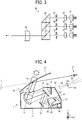
- FIG. 3 is a view illustrating a configuration example of the light emitter 22 according to the first embodiment.
- the light emitter 22 includes LDs (semiconductor laser elements) 31, 32, and 33, coupling lenses 35, 36, and 37, apertures 41, 42, and 43, a combining element 45, and a meniscus lens 46.
- LDs semiconductor laser elements
- the LDs 31, 32, 33 emit light beams having different wavelengths (for example, 640 nm, 530 nm, and 445 nm).
- the light beams emitted from the LDs 31, 32, and 33 are coupled to subsequent optical systems by the corresponding coupling lenses 35, 36, and 37.
- the light beams emitted from the coupling lenses 35, 36, and 37 are shaped by the corresponding apertures 41, 42, and 43. While the shape of the apertures 41, 42, and 43 should be appropriately selected according to use conditions (the divergence angle of a light beam or the like), the shape may be, for example, a circle, an ellipse, a rectangle, or a square.
- the light beams emitted from the apertures 41, 42, and 43 pass through the combining element 45 to be combined into one light beam that travels along one optical path.
- the combining element 45 may be, for example, a plate-like or prismatic dichroic mirror.
- the combining element 45 reflects or transmits each light beam based on the wavelength, and combines the optical paths of the light beams into one optical path.
- the meniscus lens 46 is disposed so that a surface facing the scanning unit 23 is a concave surface. The light beam combined by the combining element 45 to travel along one optical path is guided to the scanning unit 23 through the meniscus lens 46.
- FIG. 4 is a view illustrating a configuration example of the display device 1 according to the first embodiment.
- the display device 1 As the light of an original image formed by the image forming unit 12 is projected on the windshield 6 through the total reflection mirror 13, the cold mirror 14, and the concave mirror 15, the observer 5 can visually recognize the virtual image 7 through the windshield 6.
- the display device 1 has a so-called "vertical installation type" configuration.
- the image forming unit 12, the total reflection mirror 13, the cold mirror 14, and the concave mirror 15 are arranged so that the optical path of light that is emitted from the screen 25 of the image forming unit 12 and reaches the windshield 6 is placed on a substantially vertical surface (a YZ plane).
- the temperature rises at the focal point 55. If there is a certain component (an optical system, an electronic device, a casing member, or the like) at the focal point 55, the component may be damaged.
- the focal point 55 is a virtual focal point and can be specified only when the shielding part 17 and the casing 11 are not present.
- the shielding part 17 is a member that has a function of shielding or attenuating the infrared light 52 and is disposed between the cold mirror 14 and the focal point 55.
- the material and shape of the shielding part 17 should be appropriately selected according to use conditions.
- the shielding part 17 may be formed of a known or new material having a function of shielding or attenuating infrared light such as indium tin oxide and antimony tin oxide.
- the entire casing 11 may be formed of a material having the function of shielding or attenuating infrared light, and by partially extending the casing 11, the shielding part 17 may be formed.
- the shielding part 17 may be integrated with the casing 11 or may be detachable from an appropriate component such as the casing 11.
- the shielding part 17 may have a shape (for example, a plate shape or the like) capable of shielding all of the infrared light 52 transmitted through the cold mirror 14, or may have a shape (for example, a strip shape, a mesh shape or the like) capable of partially shielding the infrared light 52.
- the shielding part 17 may have any shape capable of at least attenuating the energy of the infrared light 52.
- the material and shape of the shielding part 17 are not limited to the materials and shapes described above.
- the casing 11 may be formed of a metal and the shielding part 17 may be formed as a part of the casing 11.
- the casing 11 may be formed of a resin and the shielding part 17 may be formed as a part of the casing 11.
- the casing 11 and the shielding part 17 are preferably formed of a resin in view of moldability, light-weight property, and the like.
- the resin used for the casing 11 and the shielding part 17 may be, for example, a crystalline heat-resistant polymer. More specifically, it is possible to use engineering plastics such as polybutylene terephthalate (PBT), polyethylene terephthalate (PET), polyacetal (POM), polyamide (PA), polycarbonate (PC), modified polyphenylene ether (m-PPE). In particular, it is preferable to use polybutylene terephthalate (PBT), polyphenylene sulfide (PPS), and polyethylene terephthalate (PET) because these heat-resistant polymers have a high melting point.
- PBT polybutylene terephthalate
- PET polyethylene terephthalate
- POM polyacetal
- PA polyamide
- PC polycarbonate
- m-PPE modified polyphenylene ether
- the energy density at the focal point 55 depends on the amount of the external light 51 taken in by the concave mirror 15. Assuming that the ratio of the area S of the concave mirror 15 that receives light to the area s of the focal point 55 condensed by the concave mirror 15 (S/s) is defined as a condensing magnification, when the condensing magnification is larger than or equal to 10, the irradiation density at the focal point 55 is estimated to be larger than or equal to 6600 W/m2.
- the condensing magnification is as small as possible, preferably less than 10.
- the condensing magnification changes depending on characteristics of members on the optical path of the external light 51 (in this example, the transmittance of the windshield 6 or the dustproof sheet 16, the reflectance of the concave mirror 15, and the like). If the condensing magnification is less than 10, it is less necessary to use a special material as the shielding part 17 or to perform a surface treatment for the shielding part 17, and thus the casing 11 and the shielding part 17 can be formed using, for example, a resin having good moldability.
- the light receiving surface of the shielding part 17 is not perpendicular to a light beam center 53 (the optical path) of the infrared light 52 transmitted through the cold mirror 14, that is, is inclined to a vertical plane 54 of the light beam center 53 by a predetermined angle or more. It is thus possible to increase the diameter D1 of the light receiving area in the shielding part 17 and to improve an effect of shielding or attenuating the infrared light 52.
- the diameter D1 is larger than the diameter DS of the light beam of the infrared light 52 at the focal point 55.
- the light receiving surface of the shielding part 17 according to the present embodiment is inclined to a reflecting surface of the cold mirror 14 by a predetermined angle or more.
- the position of the focal point 55, the diameters D1 and DS, and the like can be estimated based on the curvature of the concave mirror 15, the relative positions of the concave mirror 15 and the cold mirror 14, and the like.
- the shielding part 17 between the cold mirror 14 and the focal point 55, the infrared light 52 transmitted through the cold mirror 14 can be shielded or attenuated to prevent the focal point 55 from being formed or to reduce the energy at the focal point 55. It is thus possible to reliably prevent failures due to the external light 51.
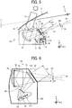
- FIG. 5 is a view illustrating a configuration example of a display device 101 according to a second embodiment.
- the present embodiment is different from the first embodiment in that the reflecting surface of the cold mirror 14 is substantially parallel to the light receiving surface of a shielding part 115 and that a casing 112 is shaped to be adjacent to the cold mirror 14. At this time, the diameter D1 of a light receiving area of the shielding part 115 is larger than a diameter D2 of a light receiving area assumed to be perpendicular to the light beam center 53.
- the shielding part 115 according to the present embodiment is disposed at a position closer to the concave mirror 15 than the shielding part 17 according to the first embodiment.
- the diameter D1 of the light receiving area of the shielding part 115 is thus larger than that of the shielding part 17 according to the first embodiment, and the irradiation density of the infrared light 52 is smaller than that of the first embodiment. It is thus possible to form the shielding part 115 using a part of the casing 11 without using a special material for the shielding part 115.
- the present embodiment is similar to the first embodiment in that the light receiving surface of the shielding part 115 is not perpendicular to the light beam center 53 of the infrared light 52 and the diameter D1 is larger than the diameter DS of the light beam at the focal point 55.
- the infrared light 52 transmitted through the cold mirror 14 can be shielded or attenuated to reliably prevent failures due to the external light 51 and the display device 101 can be downsized, as in the first embodiment. Further, it is possible to prevent the focal point 55 from being inside of the casing 11. Consequently, if foreign matter such as dust enters the casing 11, it is possible to reliably prevent the foreign matter from being heated by the focal point 55.
- FIG. 6 is a view illustrating a configuration example of a display device 201 according to a third embodiment.
- the display device 201 includes an image forming unit 211, the cold mirror 14, the concave mirror 15, and a shielding part 215, and has a so-called "horizontal installation type" configuration.
- the image forming unit 211, the cold mirror 14, and the concave mirror 15 according to the present embodiment are arranged so that light travelling from the screen 25 of the image forming unit 211 to the cold mirror 14 is placed on a substantially horizontal surface (an XZ plane) and light travelling from the concave mirror 15 to the windshield 6 is placed on the substantially vertical surface (the YZ plane).
- the image forming unit 211 forms an original image similarly to the image forming unit 12 according to the first embodiment, and includes the light emitter 22, the scanning unit 23, and the screen 25.
- the image forming unit 211 is different from the image forming unit 12 in that the image forming unit 211 does not include the deflection mirror 24.
- the display device 201 according to the present embodiment does not have a component corresponding to the total reflection mirror 13 according to the first embodiment, and light emitted from the screen 25 is directly irradiated to the cold mirror 14.
- the light receiving surface of the shielding part 215 is substantially parallel to the reflecting surface of the cold mirror 14.
- a casing 212 of the display device 201 is shaped to be adjacent to the cold mirror 14.
- the diameter D1 is larger than the diameter DS of a light beam at the focal point 55 and the diameter D2 of a light receiving area assumed to be perpendicular to the light beam center 53.
- the infrared light 52 transmitted through the cold mirror 14 can be shield or attenuated to reliably prevent failures due to the external light 51 and the display device 201 can be downsized.
- FIG. 7 is a view illustrating a configuration example of a display device 301 according to a fourth embodiment.
- the display device 301 according to the present embodiment is different from that of the third embodiment in that the light receiving surface of the shielding part 215 is inclined to the reflecting surface of the cold mirror 14 by a predetermined angle or more.
- the diameter D1 of a light receiving area of the shielding part 215 is larger than the diameter DS of a light beam at the focal point 55 and the diameter D2 of a light receiving area assumed to be perpendicular to the light beam center 53.
- FIG. 8 is a view illustrating a configuration example of a display device 401 according to a fifth embodiment.
- the display device 401 includes a hot mirror 413 (wavelength selective mirror) that reflects infrared light and transmits visible light and a shielding part 421 that shields or attenuates the infrared light 52 reflected by the hot mirror 413.
- a hot mirror 413 wavelength selective mirror
- the shielding part 421 is disposed between the hot mirror 413 and the focal point 55 of the infrared light 52. While the present embodiment exemplifies a configuration in which the shielding part 421 is provided on an inner wall surface of a casing 412, the position and shape of the shielding part 421 are not limited the position and shape described above and should be appropriately selected according to use conditions.
- the diameter D1 of a light receiving area of the shielding part 421 is larger than the diameter DS of a light beam at the focal point 55 of the infrared light 52.
Landscapes
- Physics & Mathematics (AREA)
- General Physics & Mathematics (AREA)
- Optics & Photonics (AREA)
- Health & Medical Sciences (AREA)
- Toxicology (AREA)
- Instrument Panels (AREA)
Abstract
Description
- Embodiments of the present disclosure relate to a display device and an apparatus.
- There has been used a display device such as a heads-up display (HUD) that enables an observer (a driver) to recognize various information (for example, speed information, traffic information, navigation information, warning information, and the like) with less line-of-sight movements in a mobile object such as a vehicle. Such a display device commonly projects an original image formed on a screen by laser scanning on a transmissive reflector such as a windshield, thus displaying a virtual image that can be visually recognized by the observer.
- A configuration of a vehicle HUD is disclosed, in which a cold mirror that reflects visible light and transmits infrared light is disposed on an optical path of external light (sunlight) incident on a display device for the purpose of reducing the influence of external light. In addition, a configuration is disclosed, in which a member of reducing an infrared component is disposed between a screen (a liquid crystal panel) on which an original image is formed and a concave mirror that projects light emitted from the screen on a windshield.
- By using a wavelength selective mirror such as a cold mirror, it is possible to reduce the influence of external light. When the cold mirror is used, however, it is necessary to consider the influence of infrared light after passing through the cold mirror. An optical element such as a concave mirror that reflects the light of an original image to a transmissive reflector such as a windshield has power based on the shape of a curved transmissive reflector such as a windshield. Consequently, for light reflected from a screen that displays an original image to the transmissive reflector, the optical element commonly has a function of converting diverging light into converging light for the purpose of forming a virtual image a few meters ahead of an observer. Also for light reflected from the transmissive reflector to the screen, the optical element has a light condensing function. Infrared light that is transmitted through the cold mirror via the optical element such as a concave mirror is thus condensed somewhere on the optical path and causes a temperature rise at a focal point. If a certain component (for example, an optical element, an electronic device, a casing member, or the like) is present at the focal point, infrared light having been transmitted through the cold mirror may affect the component. Conventional techniques cannot solve such problems.
- Embodiments of the present disclosure described herein provide a display device and an apparatus. The display device includes an image forming unit to form an image and project the image on a transmissive reflector to display a virtual image, an optical element to direct light of the image to the transmissive reflector, a wavelength selective mirror disposed between the image forming unit and the optical element and to separate infrared light from a light beam, and a shielding part to shield or attenuate infrared light. The optical element condenses external light travelling along an optical path opposite to an optical path of the light diffused. The wavelength selective mirror separates infrared light included in the external light condensed by the optical element, and the shielding part is disposed between the wavelength selective mirror and a focal point of the infrared light separated by the wavelength selective mirror. The apparatus includes the display device and the transmissive reflector.
- The present invention can reliably prevent failures due to external light.
- A more complete appreciation of exemplary embodiments and the many attendant advantages thereof will be readily obtained as the same becomes better understood by reference to the following detailed description when considered in connection with the accompanying drawings.
-
FIG. 1 is a view illustrating an overall configuration example of an apparatus on which a display device according to a first embodiment is mounted; -
FIG. 2 is a view illustrating a configuration example of an image forming unit according to the first embodiment; -
FIG. 3 is a view illustrating a configuration example of a light emitter according to the first embodiment; -
FIG. 4 is a view illustrating a configuration example of the display device according to the first embodiment; -
FIG. 5 is a view illustrating a configuration example of a display device according to a second embodiment; -
FIG. 6 is a view illustrating a configuration example of a display device according to a third embodiment; -
FIG. 7 is a view illustrating a configuration example of a display device according to a fourth embodiment; and -
FIG. 8 is a view illustrating a configuration example of a display device according to a fifth embodiment. - The accompanying drawings are intended to depict embodiments of the present disclosure and should not be interpreted to limit the scope thereof. The accompanying drawings are not to be considered as drawn to scale unless explicitly noted.
- The accompanying drawings are intended to depict exemplary embodiments of the present disclosure and should not be interpreted to limit the scope thereof. The accompanying drawings are not to be considered as drawn to scale unless explicitly noted.
- The terminology used herein is for the purpose of describing particular embodiments only and is not intended to be limiting of the present disclosure. As used herein, the singular forms "a", "an" and "the" are intended to include the plural forms as well, unless the context clearly indicates otherwise. It will be further understood that the terms "includes" and/or "including", when used in this specification, specify the presence of stated features, integers, steps, operations, elements, and/or components, but do not preclude the presence or addition of one or more other features, integers, steps, operations, elements, components, and/or groups thereof.
- In describing example embodiments shown in the drawings, specific terminology is employed for the sake of clarity. However, the present disclosure is not intended to be limited to the specific terminology so selected and it is to be understood that each specific element includes all technical equivalents that have the same structure, operate in a similar manner, and achieve a similar result.
- Embodiments of a display device and an apparatus will be described hereinafter in detail with reference to the accompanying drawings. The present invention is not limited by the following embodiments, and constituent elements in the following embodiments include those that can be easily conceived by those skilled in the art, those that are substantially the same, and those within the so-called equivalent scope of the invention. Various omissions, substitutions, changes, and combinations of constituent elements can be made without departing from the subject of the following embodiments.
-
FIG. 1 is a view illustrating an overall configuration example of anapparatus 2 on which a display device 1 according to a first embodiment is mounted. - The display device 1 according to the present embodiment is a HUD mounted on the
apparatus 2. Theapparatus 2 may be a mobile object such as a vehicle, an aircraft, and a vessel or an immobile object such as a steering simulation system and a home theater system. A HUD (an example of the display device 1) mounted on a vehicle (an example of the apparatus 2) will be described as an example. - The display device 1 displays a
virtual image 7 that can be visually recognized by an observer (a vehicle's driver) 5 through a windshield 6 (transmissive reflector). The display device 1 includes acasing 11, an image forming unit 12 (image forming unit), atotal reflection mirror 13, a cold mirror 14 (wavelength selective mirror), aconcave mirror 15, adustproof sheet 16, and ashielding part 17. An X axis corresponds to a width direction of theapparatus 2, a Y axis corresponds to a vertical direction of theapparatus 2, and a Z axis corresponds to a front-rear direction of theapparatus 2. - The
casing 11 is a member that constitutes an outer frame of the display device 1 and houses components such as theimage forming unit 12, thetotal reflection mirror 13, thecold mirror 14, theconcave mirror 15, and theshielding part 17. While the material and shape of thecasing 11 should be appropriately selected according to use conditions, resins that are excellent in solidity, heat resistance, light-weight property, moldability, and the like can be used. - The
image forming unit 12 includes a mechanism for forming an image (original image) that is the source of thevirtual image 7. A specific configuration of theimage forming unit 12 will be described later. - The
total reflection mirror 13 reflects light beams including visible light and infrared light. Thecold mirror 14 reflects visible light and transmits infrared light. Thetotal reflection mirror 13 reflects light (i.e., the light of an original image) emitted from theimage forming unit 12 to thecold mirror 14. Thecold mirror 14 reflects a visible light component of light emitted from thetotal reflection mirror 13 to theconcave mirror 15. WhileFIG. 1 illustrates the configuration in which light emitted from theimage forming unit 12 is irradiated to thecold mirror 14 via thetotal reflection mirror 13, the present invention is not limited to the configuration. For example, thecold mirror 14 may be directly irradiated with light emitted from theimage forming unit 12, or more mirrors may be interposed between theimage forming unit 12 and thecold mirror 14. - The
concave mirror 15 reflects the light (i.e., the visible light of an original image) emitted from thecold mirror 14 to thewindshield 6. Theconcave mirror 15 has a curved shape according to the curvature of thewindshield 6, that is, such that thevirtual image 7 is visually recognized by theobserver 5 without any distortion. Theconcave mirror 15 may be configured to be displaceable by an appropriate drive mechanism. It is thus possible to adjust the display position of thevirtual image 7 and perform distortion correction on thevirtual image 7. - The present embodiment describes the
concave mirror 15 as an optical system having a function necessary for allowing theobserver 5 to visually recognize thevirtual image 7. However, it is only required that the optical system having a function necessary for allowing theobserver 5 to visually recognize thevirtual image 7 includes a light condensing function. While the present embodiment describes an example of using theconcave mirror 15, other optical elements having an identical function to theconcave mirror 15 may be used. For example, a transmissive lens element, a Fresnel lens, a Fresnel reflective element, and a diffraction grating can be used. - In most cases, the
concave mirror 15 according to the present embodiment, which is an example of an optical element for directing light to thewindshield 6, is obtained by forming a metal thin film of aluminum, silver, or the like on a surface of a resin member, a glass member, or the like by vapor deposition, sputtering, or the like, for the purpose of maximizing light use efficiency. For this reason, the reflectance in the wavelength distribution (from the ultraviolet region of 300 nm to the near-infrared region of 800 nm to 2500 nm) of external light such as sunlight is also high. Infrared light that is reflected by theconcave mirror 15 and transmitted through thecold mirror 14 is thus condensed somewhere on an optical path and causes a temperature rise at a focal point. - The
dustproof sheet 16 is a translucent member that prevents dust from entering the display device 1. Light that constitutes an original image and is reflected by theconcave mirror 15 is irradiated to thewindshield 6 through thedustproof sheet 16. - The shielding
part 17 is a member that shields or attenuates infrared light having transmitted through thecold mirror 14. The shieldingpart 17 will be described later in detail. -
FIG. 2 is a view illustrating a configuration example of theimage forming unit 12 according to the first embodiment. - The
image forming unit 12 includes acasing 21, alight emitter 22, ascanning unit 23, adeflection mirror 24, and ascreen 25. - The
casing 21 is a member that constitutes an outer frame of theimage forming unit 12 and houses components such as thelight emitter 22, thescanning unit 23, thedeflection mirror 24, and thescreen 25. While the material and shape of thecasing 21 should be appropriately selected according to use conditions, resins that are excellent in solidity, heat resistance, light-weight property, moldability, and the like can be used. Thelight emitter 22 is a mechanism that emits laser light and is constituted by, for example, a light source element, a condensing optical system, a collimating optical system, and a diffusion optical system. Thescanning unit 23 is a mechanism that changes a traveling direction of laser light emitted from thelight emitter 22, and is constituted by, for example, a micro electro mechanical systems (MEMS) mirror and a circuit (a microprocessor, a logic circuit, or the like) for controlling an operation of the MEMS mirror. Thedeflection mirror 24 reflects laser light emitted from thescanning unit 23. Thescreen 25 is an optical element that receives laser light emitted from thedeflection mirror 24. While the specific configuration of thescreen 25 should be appropriately selected according to use conditions and the like, thescreen 25 may be constituted by, for example, a micro lens array. Thescanning unit 23 functions to scan thescreen 25 with laser light. By controlling operations of thelight emitter 22 and thescanning unit 23 according to the configuration of thevirtual image 7 including desired information, an original image is formed on thescreen 25. As thedeflection mirror 24 is disposed mainly for downsizing the image forming unit 12 (the casing 21), theimage forming unit 12 may be configured without thedeflection mirror 24, that is, may be configured that laser light emitted from thescanning unit 23 directly scans thescreen 25. -
FIG. 3 is a view illustrating a configuration example of thelight emitter 22 according to the first embodiment. - The
light emitter 22 according to this example includes LDs (semiconductor laser elements) 31, 32, and 33,coupling lenses apertures element 45, and ameniscus lens 46. - The
LDs LDs coupling lenses coupling lenses apertures apertures apertures element 45 to be combined into one light beam that travels along one optical path. While the specific configuration of the combiningelement 45 should be appropriately selected according to use conditions, the combiningelement 45 may be, for example, a plate-like or prismatic dichroic mirror. In this case, the combiningelement 45 reflects or transmits each light beam based on the wavelength, and combines the optical paths of the light beams into one optical path. Themeniscus lens 46 is disposed so that a surface facing thescanning unit 23 is a concave surface. The light beam combined by the combiningelement 45 to travel along one optical path is guided to thescanning unit 23 through themeniscus lens 46. -
FIG. 4 is a view illustrating a configuration example of the display device 1 according to the first embodiment. - As the light of an original image formed by the
image forming unit 12 is projected on thewindshield 6 through thetotal reflection mirror 13, thecold mirror 14, and theconcave mirror 15, theobserver 5 can visually recognize thevirtual image 7 through thewindshield 6. The display device 1 according to the present embodiment has a so-called "vertical installation type" configuration. Theimage forming unit 12, thetotal reflection mirror 13, thecold mirror 14, and theconcave mirror 15 are arranged so that the optical path of light that is emitted from thescreen 25 of theimage forming unit 12 and reaches thewindshield 6 is placed on a substantially vertical surface (a YZ plane). - When entering the
casing 11 of the display device 1 through thewindshield 6 and thedustproof sheet 16,external light 51 including sunlight and the like is reflected by theconcave mirror 15 to be irradiated to thecold mirror 14. At this time,infrared light 52 included in theexternal light 51 transmits through thecold mirror 14. As theconcave mirror 15 is curved according to the curvature of thewindshield 6, theconcave mirror 15 has a light condensing effect on light reflected from thewindshield 6 to thecold mirror 14. Consequently, theinfrared light 52 that is reflected by theconcave mirror 15 to transmit through thecold mirror 14 is condensed on the rear side of thecold mirror 14. That is, afocal point 55 where a diameter DS of a light beam of theinfrared light 52 is minimized appears on the optical path of theinfrared light 52 extending to the rear side of thecold mirror 14. The temperature rises at thefocal point 55. If there is a certain component (an optical system, an electronic device, a casing member, or the like) at thefocal point 55, the component may be damaged. Note that thefocal point 55 is a virtual focal point and can be specified only when the shieldingpart 17 and thecasing 11 are not present. - The shielding
part 17 according to the present embodiment is a member that has a function of shielding or attenuating theinfrared light 52 and is disposed between thecold mirror 14 and thefocal point 55. The material and shape of the shieldingpart 17 should be appropriately selected according to use conditions. The shieldingpart 17 may be formed of a known or new material having a function of shielding or attenuating infrared light such as indium tin oxide and antimony tin oxide. Theentire casing 11 may be formed of a material having the function of shielding or attenuating infrared light, and by partially extending thecasing 11, the shieldingpart 17 may be formed. The shieldingpart 17 may be integrated with thecasing 11 or may be detachable from an appropriate component such as thecasing 11. In addition, the shieldingpart 17 may have a shape (for example, a plate shape or the like) capable of shielding all of theinfrared light 52 transmitted through thecold mirror 14, or may have a shape (for example, a strip shape, a mesh shape or the like) capable of partially shielding theinfrared light 52. The shieldingpart 17 may have any shape capable of at least attenuating the energy of theinfrared light 52. - The material and shape of the shielding
part 17 are not limited to the materials and shapes described above. For example, thecasing 11 may be formed of a metal and the shieldingpart 17 may be formed as a part of thecasing 11. Alternatively, thecasing 11 may be formed of a resin and the shieldingpart 17 may be formed as a part of thecasing 11. For example, when thefocal point 55 is located at a position separated from the shieldingpart 17 by a predetermined distance (for example, a distance at which theinfrared light 52 is less likely to damage a component) or longer, thecasing 11 and the shieldingpart 17 are preferably formed of a resin in view of moldability, light-weight property, and the like. The resin used for thecasing 11 and the shieldingpart 17 may be, for example, a crystalline heat-resistant polymer. More specifically, it is possible to use engineering plastics such as polybutylene terephthalate (PBT), polyethylene terephthalate (PET), polyacetal (POM), polyamide (PA), polycarbonate (PC), modified polyphenylene ether (m-PPE). In particular, it is preferable to use polybutylene terephthalate (PBT), polyphenylene sulfide (PPS), and polyethylene terephthalate (PET) because these heat-resistant polymers have a high melting point. - While the energy of the
infrared light 52 depends on the weather, the solar altitude, and the like, the energy is considered to be approximately 60% of the sunlight energy immediately below the equator, which is approximately 1100 W/m2, at most. The energy density at thefocal point 55 depends on the amount of theexternal light 51 taken in by theconcave mirror 15. Assuming that the ratio of the area S of theconcave mirror 15 that receives light to the area s of thefocal point 55 condensed by the concave mirror 15 (S/s) is defined as a condensing magnification, when the condensing magnification is larger than or equal to 10, the irradiation density at thefocal point 55 is estimated to be larger than or equal to 6600 W/m2. At thefocal point 55 with the irradiation density described above, there is a possibility of a large temperature rise. For this reason, the condensing magnification is as small as possible, preferably less than 10. The condensing magnification changes depending on characteristics of members on the optical path of the external light 51 (in this example, the transmittance of thewindshield 6 or thedustproof sheet 16, the reflectance of theconcave mirror 15, and the like). If the condensing magnification is less than 10, it is less necessary to use a special material as the shieldingpart 17 or to perform a surface treatment for the shieldingpart 17, and thus thecasing 11 and the shieldingpart 17 can be formed using, for example, a resin having good moldability. - Preferably, the light receiving surface of the shielding
part 17 is not perpendicular to a light beam center 53 (the optical path) of theinfrared light 52 transmitted through thecold mirror 14, that is, is inclined to avertical plane 54 of thelight beam center 53 by a predetermined angle or more. It is thus possible to increase the diameter D1 of the light receiving area in the shieldingpart 17 and to improve an effect of shielding or attenuating theinfrared light 52. The diameter D1 is larger than the diameter DS of the light beam of theinfrared light 52 at thefocal point 55. The light receiving surface of the shieldingpart 17 according to the present embodiment is inclined to a reflecting surface of thecold mirror 14 by a predetermined angle or more. The position of thefocal point 55, the diameters D1 and DS, and the like can be estimated based on the curvature of theconcave mirror 15, the relative positions of theconcave mirror 15 and thecold mirror 14, and the like. - As described above, by disposing the shielding
part 17 between thecold mirror 14 and thefocal point 55, theinfrared light 52 transmitted through thecold mirror 14 can be shielded or attenuated to prevent thefocal point 55 from being formed or to reduce the energy at thefocal point 55. It is thus possible to reliably prevent failures due to theexternal light 51. - Hereinafter, other embodiments will be described with reference to the drawings. Parts having the same or identical operations and effects as those of the first embodiment are denoted by the same reference numerals and descriptions thereof may be omitted.
-
FIG. 5 is a view illustrating a configuration example of adisplay device 101 according to a second embodiment. - The present embodiment is different from the first embodiment in that the reflecting surface of the
cold mirror 14 is substantially parallel to the light receiving surface of a shieldingpart 115 and that acasing 112 is shaped to be adjacent to thecold mirror 14. At this time, the diameter D1 of a light receiving area of the shieldingpart 115 is larger than a diameter D2 of a light receiving area assumed to be perpendicular to thelight beam center 53. - In addition, the shielding
part 115 according to the present embodiment is disposed at a position closer to theconcave mirror 15 than the shieldingpart 17 according to the first embodiment. The diameter D1 of the light receiving area of the shieldingpart 115 is thus larger than that of the shieldingpart 17 according to the first embodiment, and the irradiation density of theinfrared light 52 is smaller than that of the first embodiment. It is thus possible to form the shieldingpart 115 using a part of thecasing 11 without using a special material for the shieldingpart 115. - The present embodiment is similar to the first embodiment in that the light receiving surface of the shielding
part 115 is not perpendicular to thelight beam center 53 of theinfrared light 52 and the diameter D1 is larger than the diameter DS of the light beam at thefocal point 55. - According to the present embodiment, the
infrared light 52 transmitted through thecold mirror 14 can be shielded or attenuated to reliably prevent failures due to theexternal light 51 and thedisplay device 101 can be downsized, as in the first embodiment. Further, it is possible to prevent thefocal point 55 from being inside of thecasing 11. Consequently, if foreign matter such as dust enters thecasing 11, it is possible to reliably prevent the foreign matter from being heated by thefocal point 55. -
FIG. 6 is a view illustrating a configuration example of adisplay device 201 according to a third embodiment. - The
display device 201 according to the present embodiment includes animage forming unit 211, thecold mirror 14, theconcave mirror 15, and a shieldingpart 215, and has a so-called "horizontal installation type" configuration. Theimage forming unit 211, thecold mirror 14, and theconcave mirror 15 according to the present embodiment are arranged so that light travelling from thescreen 25 of theimage forming unit 211 to thecold mirror 14 is placed on a substantially horizontal surface (an XZ plane) and light travelling from theconcave mirror 15 to thewindshield 6 is placed on the substantially vertical surface (the YZ plane). - The
image forming unit 211 according to the present embodiment forms an original image similarly to theimage forming unit 12 according to the first embodiment, and includes thelight emitter 22, thescanning unit 23, and thescreen 25. Theimage forming unit 211 is different from theimage forming unit 12 in that theimage forming unit 211 does not include thedeflection mirror 24. In addition, thedisplay device 201 according to the present embodiment does not have a component corresponding to thetotal reflection mirror 13 according to the first embodiment, and light emitted from thescreen 25 is directly irradiated to thecold mirror 14. - In the present embodiment, the light receiving surface of the shielding
part 215 is substantially parallel to the reflecting surface of thecold mirror 14. Further, acasing 212 of thedisplay device 201 is shaped to be adjacent to thecold mirror 14. In this case, the diameter D1 is larger than the diameter DS of a light beam at thefocal point 55 and the diameter D2 of a light receiving area assumed to be perpendicular to thelight beam center 53. - According to the present embodiment, in the so-called "horizontal installation type"
display device 201, theinfrared light 52 transmitted through thecold mirror 14 can be shield or attenuated to reliably prevent failures due to theexternal light 51 and thedisplay device 201 can be downsized. -
FIG. 7 is a view illustrating a configuration example of adisplay device 301 according to a fourth embodiment. - The
display device 301 according to the present embodiment is different from that of the third embodiment in that the light receiving surface of the shieldingpart 215 is inclined to the reflecting surface of thecold mirror 14 by a predetermined angle or more. The diameter D1 of a light receiving area of the shieldingpart 215 is larger than the diameter DS of a light beam at thefocal point 55 and the diameter D2 of a light receiving area assumed to be perpendicular to thelight beam center 53. - With such a configuration, similar effects as those of the third embodiment can be achieved.
-
FIG. 8 is a view illustrating a configuration example of adisplay device 401 according to a fifth embodiment. - The
display device 401 according to the present embodiment includes a hot mirror 413 (wavelength selective mirror) that reflects infrared light and transmits visible light and a shieldingpart 421 that shields or attenuates theinfrared light 52 reflected by thehot mirror 413. - Light emitted from the
screen 25 of theimage forming unit 211 is transmitted through thehot mirror 413 to be irradiated to theconcave mirror 15. Theinfrared light 52 included in theexternal light 51 entering from above and reflected by theconcave mirror 15 is reflected by thehot mirror 413. The shieldingpart 421 is disposed between thehot mirror 413 and thefocal point 55 of theinfrared light 52. While the present embodiment exemplifies a configuration in which theshielding part 421 is provided on an inner wall surface of acasing 412, the position and shape of the shieldingpart 421 are not limited the position and shape described above and should be appropriately selected according to use conditions. The diameter D1 of a light receiving area of the shieldingpart 421 is larger than the diameter DS of a light beam at thefocal point 55 of theinfrared light 52. - According to the configuration described above, it is possible to prevent the
infrared light 52 included in the external light 51 from being condensed at the position where theimage forming unit 211 and other components are disposed and to shield or attenuate theinfrared light 52 reflected by thehot mirror 413, thus reliably preventing failures due to theexternal light 51. - Numerous additional modifications and variations are possible in light of the above teachings. It is therefore to be understood that within the scope of the appended claims, the disclosure of the present disclosure may be practiced otherwise than as specifically described herein. For example, elements and/or features of different illustrative embodiments may be combined with each other and/or substituted for each other within the scope of this disclosure and appended claims.
Claims (11)
- A display device (1) comprising:an image forming unit (12) configured to form an image and project the image on a transmissive reflector (6) to display a virtual image (7);an optical element (15) configured to direct light of the image to the transmissive reflector (6);a wavelength selective mirror (14) disposed between the image forming unit (12) and the optical element (15) and configured to separate infrared light (52) from a light beam; anda shielding part (17) configured to shield or attenuate infrared light (52),wherein the optical element (15) condenses external light (51) travelling along an optical path opposite to an optical path of the light diffused,wherein the wavelength selective mirror (14) separates infrared light (52) included in the external light (51) condensed by the optical element (15), andwherein the shielding part (17) is disposed between the wavelength selective mirror (14) and a focal point (55) of the infrared light (52) separated by the wavelength selective mirror (14).
- The display device (1) according to claim 1, wherein the optical element (15) is a concave mirror that reflects the light of the image to the transmissive reflector (6).
- The display device (1) according to claim 1 or 2, wherein a light receiving surface of the shielding part (17) is inclined to a vertical surface of an optical path of the infrared light (52) separated by the wavelength selective mirror (14) by a predetermined angle or more.
- The display device (1) according to any one of claims 1 to 3, wherein a light receiving surface of the shielding part (17) is parallel to a reflecting surface of the wavelength selective mirror (14).
- The display device (1) according to any one of claims 1 to 4, wherein a diameter of a light receiving area of the shielding part (17) for the infrared light (52) separated by the wavelength selective mirror (14) is larger than a diameter of a light beam of the infrared light (52) at the focal point (55).
- The display device (1) according to any one of claims 1 to 5, wherein a diameter of a light receiving area of the shielding part (17) for the infrared light (52) separated by the wavelength selective mirror (14) is larger than a diameter where the light receiving area is assumed to be perpendicular to an optical path of the infrared light (52) separated by the wavelength selective mirror (14).
- The display device (1) according to any one of claims 1 to 6, wherein the image forming unit (12), the wavelength selective mirror (14), and the optical element (15) are arranged to place light traveling from the image forming unit (12) to the wavelength selective mirror (14) on a horizontal plane.
- The display device (1) according to any one of claims 1 to 7, wherein the wavelength selective mirror (14) reflects visible light and transmits infrared light (52).
- The display device (1) according to any one of claims 1 to 7, wherein the wavelength selective mirror (14) reflects infrared light (52) and transmits visible light.
- An apparatus comprising:the display device (1) according to any one of claims 1 to 9; andthe transmissive reflector (6).
- The apparatus according to claim 10, wherein the transmissive reflector (6) is a member including a curved surface.
Applications Claiming Priority (1)
| Application Number | Priority Date | Filing Date | Title |
|---|---|---|---|
| JP2018050241A JP7000937B2 (en) | 2018-03-16 | 2018-03-16 | Display devices and equipment |
Publications (1)
| Publication Number | Publication Date |
|---|---|
| EP3543751A1 true EP3543751A1 (en) | 2019-09-25 |
Family
ID=65234431
Family Applications (1)
| Application Number | Title | Priority Date | Filing Date |
|---|---|---|---|
| EP19153577.2A Withdrawn EP3543751A1 (en) | 2018-03-16 | 2019-01-24 | Display device and apparatus |
Country Status (3)
| Country | Link |
|---|---|
| US (1) | US11061227B2 (en) |
| EP (1) | EP3543751A1 (en) |
| JP (1) | JP7000937B2 (en) |
Cited By (1)
| Publication number | Priority date | Publication date | Assignee | Title |
|---|---|---|---|---|
| EP3879331A1 (en) * | 2020-03-10 | 2021-09-15 | Yazaki Corporation | Vehicular display device |
Families Citing this family (6)
| Publication number | Priority date | Publication date | Assignee | Title |
|---|---|---|---|---|
| JP6726674B2 (en) * | 2015-10-15 | 2020-07-22 | マクセル株式会社 | Information display device |
| US11135917B2 (en) * | 2018-09-05 | 2021-10-05 | Denso International America, Inc. | Forward collision avoidance display |
| EP3657232B1 (en) | 2018-11-08 | 2023-01-04 | Ricoh Company, Ltd. | Display device, display system, and mobile object |
| JP7200775B2 (en) | 2019-03-18 | 2023-01-10 | 株式会社リコー | Projection device, display system and moving object |
| US11953816B2 (en) | 2021-08-06 | 2024-04-09 | Ricoh Company, Ltd. | Wavelength conversion plate, light source device, and image projection apparatus |
| US20240004192A1 (en) * | 2022-07-01 | 2024-01-04 | N.S. International, Ltd. | Head up display with improved resistance to sunload for use in a vehicle |
Citations (3)
| Publication number | Priority date | Publication date | Assignee | Title |
|---|---|---|---|---|
| JP2004347633A (en) * | 2003-05-20 | 2004-12-09 | Nippon Seiki Co Ltd | Head-up display device |
| JP2018022102A (en) * | 2016-08-05 | 2018-02-08 | 株式会社デンソー | Head-up display device |
| WO2018062302A1 (en) * | 2016-09-29 | 2018-04-05 | 日立マクセル株式会社 | Head-up display device |
Family Cites Families (19)
| Publication number | Priority date | Publication date | Assignee | Title |
|---|---|---|---|---|
| JP2505383Y2 (en) * | 1990-09-20 | 1996-07-31 | 富士通株式会社 | Holographic head up display |
| JP2003344801A (en) | 2002-05-28 | 2003-12-03 | Nippon Seiki Co Ltd | Display device |
| JP4788882B2 (en) | 2005-08-29 | 2011-10-05 | 日本精機株式会社 | Head-up display device |
| JP2012058270A (en) | 2010-09-03 | 2012-03-22 | Yazaki Corp | Display device for vehicle |
| JP6070982B2 (en) | 2012-10-04 | 2017-02-01 | 日本精機株式会社 | Display device |
| JP6206087B2 (en) | 2013-10-28 | 2017-10-04 | 株式会社Jvcケンウッド | Image display device |
| JP6340807B2 (en) | 2014-02-05 | 2018-06-13 | 株式会社リコー | Image display device and moving body |
| DE102014008201A1 (en) * | 2014-05-30 | 2015-12-03 | Audi Ag | Display device for a motor vehicle and motor vehicle |
| JP6372346B2 (en) | 2014-12-24 | 2018-08-15 | 日本精機株式会社 | Head-up display |
| JP6563711B2 (en) | 2015-06-24 | 2019-08-21 | デクセリアルズ株式会社 | Head-up display device |
| JP6288007B2 (en) | 2015-08-26 | 2018-03-07 | 株式会社デンソー | Head-up display device and reflection optical system |
| JP6642172B2 (en) | 2016-03-24 | 2020-02-05 | 日本精機株式会社 | Head-up display device |
| JP6593254B2 (en) * | 2016-06-06 | 2019-10-23 | 株式会社デンソー | Head-up display device and cold mirror |
| JP2018010138A (en) | 2016-07-13 | 2018-01-18 | 株式会社リコー | Display, projection device, and movable body including display or projection device |
| JP2018036501A (en) | 2016-08-31 | 2018-03-08 | パイオニア株式会社 | Virtual image display device |
| JP6638077B2 (en) * | 2016-09-06 | 2020-01-29 | マクセル株式会社 | Head-up display device and video display device therefor |
| JP6923322B2 (en) | 2017-01-18 | 2021-08-18 | デュアリタス リミテッド | Image display device |
| EP3370103A1 (en) | 2017-03-02 | 2018-09-05 | Ricoh Company Ltd. | Display device and apparatus |
| EP3376280B1 (en) | 2017-03-15 | 2023-04-05 | Ricoh Company, Ltd. | Display device and apparatus |
-
2018
- 2018-03-16 JP JP2018050241A patent/JP7000937B2/en active Active
-
2019
- 2019-01-24 EP EP19153577.2A patent/EP3543751A1/en not_active Withdrawn
- 2019-02-07 US US16/269,597 patent/US11061227B2/en not_active Expired - Fee Related
Patent Citations (4)
| Publication number | Priority date | Publication date | Assignee | Title |
|---|---|---|---|---|
| JP2004347633A (en) * | 2003-05-20 | 2004-12-09 | Nippon Seiki Co Ltd | Head-up display device |
| JP2018022102A (en) * | 2016-08-05 | 2018-02-08 | 株式会社デンソー | Head-up display device |
| US20190162961A1 (en) * | 2016-08-05 | 2019-05-30 | Denso Corporation | Head-up display device |
| WO2018062302A1 (en) * | 2016-09-29 | 2018-04-05 | 日立マクセル株式会社 | Head-up display device |
Cited By (1)
| Publication number | Priority date | Publication date | Assignee | Title |
|---|---|---|---|---|
| EP3879331A1 (en) * | 2020-03-10 | 2021-09-15 | Yazaki Corporation | Vehicular display device |
Also Published As
| Publication number | Publication date |
|---|---|
| US11061227B2 (en) | 2021-07-13 |
| US20190285884A1 (en) | 2019-09-19 |
| JP7000937B2 (en) | 2022-01-19 |
| JP2019159285A (en) | 2019-09-19 |
Similar Documents
| Publication | Publication Date | Title |
|---|---|---|
| US11061227B2 (en) | Display device and apparatus | |
| US10976544B2 (en) | Display device and apparatus | |
| JP7561512B2 (en) | Information display device | |
| CN106605166B (en) | Projection apparatus and head-up display apparatus | |
| CN109952527B (en) | Information display device | |
| US10393935B2 (en) | Head-up display for a motor vehicle | |
| JP6600099B2 (en) | Head-up display device | |
| US20220066209A1 (en) | Head-up display device | |
| EP3415973B1 (en) | Display device and head-up display | |
| EP3330769B1 (en) | Head-up display device | |
| WO2020166286A1 (en) | Vehicle information display apparatus and information display system for vehicle | |
| JP2017049371A (en) | Head-up display device | |
| JP7531145B2 (en) | Head-up display | |
| US11226485B2 (en) | Image projection device and moving body | |
| JP2017009855A (en) | Head-up display device | |
| JP2016173583A (en) | Projection device and head-up display device | |
| CN117092823A (en) | Optical imaging system and head-up display | |
| EP3451045B1 (en) | Display device | |
| JP2017187528A (en) | Head-up display device | |
| CN113518724A (en) | Method for influencing a light beam in the interior of a motor vehicle, motor vehicle for carrying out the method and mirror arrangement for such a motor vehicle | |
| WO2020044709A1 (en) | Head-up display | |
| CN115903302B (en) | Backlight module, head-up display device and transportation tool | |
| US20240168287A1 (en) | Image projection device | |
| JP2025085522A (en) | Optical member and image projection device | |
| CN120972365A (en) | Stray light blocking structure and its design method, head-up display device |
Legal Events
| Date | Code | Title | Description |
|---|---|---|---|
| PUAI | Public reference made under article 153(3) epc to a published international application that has entered the european phase |
Free format text: ORIGINAL CODE: 0009012 |
|
| STAA | Information on the status of an ep patent application or granted ep patent |
Free format text: STATUS: REQUEST FOR EXAMINATION WAS MADE |
|
| 17P | Request for examination filed |
Effective date: 20190124 |
|
| AK | Designated contracting states |
Kind code of ref document: A1 Designated state(s): AL AT BE BG CH CY CZ DE DK EE ES FI FR GB GR HR HU IE IS IT LI LT LU LV MC MK MT NL NO PL PT RO RS SE SI SK SM TR |
|
| AX | Request for extension of the european patent |
Extension state: BA ME |
|
| STAA | Information on the status of an ep patent application or granted ep patent |
Free format text: STATUS: EXAMINATION IS IN PROGRESS |
|
| 17Q | First examination report despatched |
Effective date: 20220304 |
|
| STAA | Information on the status of an ep patent application or granted ep patent |
Free format text: STATUS: THE APPLICATION IS DEEMED TO BE WITHDRAWN |
|
| 18D | Application deemed to be withdrawn |
Effective date: 20250801 |